EP2736026A1 - Device for reading out a magnetic strip and/or chip card with a camera for detecting inserted skimming modules - Google Patents
Device for reading out a magnetic strip and/or chip card with a camera for detecting inserted skimming modules Download PDFInfo
- Publication number
- EP2736026A1 EP2736026A1 EP12194205.6A EP12194205A EP2736026A1 EP 2736026 A1 EP2736026 A1 EP 2736026A1 EP 12194205 A EP12194205 A EP 12194205A EP 2736026 A1 EP2736026 A1 EP 2736026A1
- Authority
- EP
- European Patent Office
- Prior art keywords
- image
- card reader
- transport path
- unit
- pattern
- Prior art date
- Legal status (The legal status is an assumption and is not a legal conclusion. Google has not performed a legal analysis and makes no representation as to the accuracy of the status listed.)
- Granted
Links
- 238000001514 detection method Methods 0.000 claims description 14
- 238000000034 method Methods 0.000 claims description 5
- 230000001360 synchronised effect Effects 0.000 claims description 4
- 238000003780 insertion Methods 0.000 claims description 2
- 230000037431 insertion Effects 0.000 claims description 2
- 230000008569 process Effects 0.000 claims description 2
- 238000001454 recorded image Methods 0.000 description 5
- 230000003287 optical effect Effects 0.000 description 2
- 241000238634 Libellulidae Species 0.000 description 1
- 230000005540 biological transmission Effects 0.000 description 1
- 230000008859 change Effects 0.000 description 1
- 230000007123 defense Effects 0.000 description 1
- 230000001419 dependent effect Effects 0.000 description 1
- 238000011161 development Methods 0.000 description 1
- 230000018109 developmental process Effects 0.000 description 1
- 230000007246 mechanism Effects 0.000 description 1
- 238000012567 pattern recognition method Methods 0.000 description 1
- 239000012780 transparent material Substances 0.000 description 1
Images


Classifications
-
- G—PHYSICS
- G07—CHECKING-DEVICES
- G07F—COIN-FREED OR LIKE APPARATUS
- G07F19/00—Complete banking systems; Coded card-freed arrangements adapted for dispensing or receiving monies or the like and posting such transactions to existing accounts, e.g. automatic teller machines
- G07F19/20—Automatic teller machines [ATMs]
- G07F19/205—Housing aspects of ATMs
- G07F19/2055—Anti-skimming aspects at ATMs
-
- G—PHYSICS
- G06—COMPUTING; CALCULATING OR COUNTING
- G06K—GRAPHICAL DATA READING; PRESENTATION OF DATA; RECORD CARRIERS; HANDLING RECORD CARRIERS
- G06K7/00—Methods or arrangements for sensing record carriers, e.g. for reading patterns
- G06K7/0004—Hybrid readers
-
- G—PHYSICS
- G06—COMPUTING; CALCULATING OR COUNTING
- G06K—GRAPHICAL DATA READING; PRESENTATION OF DATA; RECORD CARRIERS; HANDLING RECORD CARRIERS
- G06K7/00—Methods or arrangements for sensing record carriers, e.g. for reading patterns
- G06K7/0013—Methods or arrangements for sensing record carriers, e.g. for reading patterns by galvanic contacts, e.g. card connectors for ISO-7816 compliant smart cards or memory cards, e.g. SD card readers
- G06K7/0056—Methods or arrangements for sensing record carriers, e.g. for reading patterns by galvanic contacts, e.g. card connectors for ISO-7816 compliant smart cards or memory cards, e.g. SD card readers housing of the card connector
-
- G—PHYSICS
- G06—COMPUTING; CALCULATING OR COUNTING
- G06K—GRAPHICAL DATA READING; PRESENTATION OF DATA; RECORD CARRIERS; HANDLING RECORD CARRIERS
- G06K7/00—Methods or arrangements for sensing record carriers, e.g. for reading patterns
- G06K7/08—Methods or arrangements for sensing record carriers, e.g. for reading patterns by means detecting the change of an electrostatic or magnetic field, e.g. by detecting change of capacitance between electrodes
- G06K7/082—Methods or arrangements for sensing record carriers, e.g. for reading patterns by means detecting the change of an electrostatic or magnetic field, e.g. by detecting change of capacitance between electrodes using inductive or magnetic sensors
- G06K7/083—Methods or arrangements for sensing record carriers, e.g. for reading patterns by means detecting the change of an electrostatic or magnetic field, e.g. by detecting change of capacitance between electrodes using inductive or magnetic sensors inductive
-
- G—PHYSICS
- G07—CHECKING-DEVICES
- G07F—COIN-FREED OR LIKE APPARATUS
- G07F19/00—Complete banking systems; Coded card-freed arrangements adapted for dispensing or receiving monies or the like and posting such transactions to existing accounts, e.g. automatic teller machines
- G07F19/20—Automatic teller machines [ATMs]
- G07F19/207—Surveillance aspects at ATMs
Landscapes
- Physics & Mathematics (AREA)
- General Physics & Mathematics (AREA)
- Engineering & Computer Science (AREA)
- Business, Economics & Management (AREA)
- Accounting & Taxation (AREA)
- Finance (AREA)
- Computer Vision & Pattern Recognition (AREA)
- Theoretical Computer Science (AREA)
- Artificial Intelligence (AREA)
- Image Input (AREA)
- Control Of Vending Devices And Auxiliary Devices For Vending Devices (AREA)
- Inspection Of Paper Currency And Valuable Securities (AREA)
- Financial Or Insurance-Related Operations Such As Payment And Settlement (AREA)
- Credit Cards Or The Like (AREA)
- Cash Registers Or Receiving Machines (AREA)
Abstract
Description
Die Erfindung betrifft eine Vorrichtung zum Lesen einer Magnetstreifen- und/oder Chipkarte, die einen Kartenleser zum Auslesen von Daten aus einer Magnetstreifen- und/oder Chipkarte umfasst, der einen Transportweg hat, entlang dessen die Magnetstreifen- und/oder Chipkarte beim Einführen in den Kartenleser und/oder Entnehmen aus dem Kartenleser bewegt wird. Ferner hat die Vorrichtung eine Bildaufnahmeeinheit zur Aufnahme von Bildern des Kartenlesers.The invention relates to a device for reading a magnetic stripe and / or chip card, comprising a card reader for reading data from a magnetic stripe and / or chip card having a transport path along which the magnetic stripe and / or chip card when inserted into the Card reader and / or removal is moved from the card reader. Further, the apparatus has an image pickup unit for picking up images of the card reader.
Solche Vorrichtungen zum Auslesen von Magnetstreifen- und/oder Chipkarten werden insbesondere in Geldautomaten, automatischen Kassensystemen, automatischen Tresorkassen und Bezahlterminals eingesetzt. Bei der Magnetstreifen- und/oder Chipkarte handelt es sich insbesondere um eine EC-Karte oder eine Kreditkarte, mit deren Hilfe eingekaufte Waren bezahlt werden oder Geld abgehoben werden soll. Um an die Kontodaten, die auf der Magnetstreifen- und/oder Chipkarte gespeichert sind und die, zugehörige PIN zu gelangen werden, illegale Skimmingangriffe durchgeführt, bei denen vor dem Schlitz, in dem die Magnetstreifen- und/oder Chipkarte eingeführt wird, ein sogenanntes Skimmingmodul vorgesehen wird, mit dessen Hilfe die Daten der Magnetstreifen- und/oder Chipkarte ausgelesen werden. Zusätzlich wird die PIN, beispielsweise mit einer verdeckt angebrachten Kamera oder einer Manipulation der Tastatur erspäht, sodass die diesen Skimmingangriff durchführende Person sowohl die Daten der Magnetstreifen- und/oder Chipkarte als auch den zugehörige PIN kennen und somit unberechtigt Geld abheben oder Einkäufe tätigen kann.Such devices for reading magnetic stripe and / or chip cards are used in particular in ATMs, automatic POS systems, automatic cash safes and payment terminals. The magnetic stripe and / or chip card is, in particular, a debit card or a credit card, with the aid of which purchased goods are to be paid or money withdrawn. In order to get to the account data, which are stored on the magnetic stripe and / or chip card and the associated PIN, carried out illegal skimming attacks in which before the slot in which the magnetic stripe and / or chip card is inserted, a so-called skimming module is provided, with the help of which the data of the magnetic stripe and / or chip card are read out. In addition, the PIN, for example, with a covert camera or a manipulation of the keyboard spied so that the person performing this skimming attack know both the data of the magnetic stripe and / or chip card and the associated PIN and thus unauthorized withdraw money or make purchases.
Zur Abwehr solcher Skimmingangriffe ist es aus dem Dokument
Aus dem Dokument
Weitere Verfahren zur Skimmingabwehr, bei dem die Geldautomaten selbst oder der Bereich vor dem Geldautomaten mit Hilfe einer Kamera überwacht wird, sind beispielsweise aus en Dokumenten
All diesen bekannten kamerabasierten Skimmingabwehrverfahren ist gemeinsam, dass mit Hilfe der Kamera nur der äußere Bereich des Geldautomaten bzw. der Vorrichtung, in der die Vorrichtung zum Lesen der Magnetstreifen- und/oder Chipkarten eingebaut ist, überwacht wird.All these known camera-based Skimmingabwehrverfahren has in common that with the help of the camera only the outer area of the ATM or the device in which the device is installed for reading the magnetic stripe and / or chip cards, is monitored.
Um solche Skimmingabwehrverfahren zu umgehen werden neuerdings Miniaturskimmingmodule in den Transportweg des Kartenlesers, insbesondere in den Schlitz, in den auch die Magnetstreifen- und/oder Chipkarte eingeführt wird, eingeführt. Über diese Miniaturskimmingmodule werden die Daten ausgelesen. Solche in den Kartenleser eingeführten Skimmingmodule können mit bekannten Skimmingabwehrverfahren nicht erkannt werden.In order to circumvent such Skimmingabwehrverfahren miniature skimming modules are recently introduced into the transport path of the card reader, in particular in the slot into which the magnetic stripe and / or chip card is inserted. The data is read out via these miniature skimming modules. Such introduced into the card reader skimming modules can not be detected with known Skimmingabwehrverfahren.
Es ist Aufgabe der Erfindung, eine Vorrichtung zum Lesen einer Magnetstreifen- und/oder Chipkarte anzugeben, mit deren Hilfe in den Transportweg des Kartenlesers der Vorrichtung eingeführte Skimmingmodule auf einfache Weise sicher detektiert werden können.It is an object of the invention to provide a device for reading a magnetic stripe and / or chip card, with the aid of which in the transport path of the card reader of the device introduced skimming modules can be reliably detected in a simple manner.
Diese Aufgabe wird hier in der Vorrichtung mit den Merkmalen des Anspruchs 1 gelöst. Vorteilhafte Weiterbildungen der Erfindung sind in den abhängigen Ansprüchen angegeben.This object is achieved here in the device with the features of claim 1. Advantageous developments of the invention are specified in the dependent claims.
Erfindungsgemäß ist der Kartenleser derart ausgebildet, dass mit Hilfe von durch die Kamera aufgenommenen Bildern detektierbar ist, ob im Transportweg des Kartenlesers ein Skimmingmodul zum Ausspähen von Daten der Magnetstreifen- und/oder Chipkarte aufgenommen ist. Dadurch dass der Kartenleser konstruktiv so gebaut ist, dass mit Hilfe der Kamera auch erkannt werden kann, ob ein Skimmingmodul innerhalb des Transportweges des Kartenlesers aufgenommen ist, können auch die neuartigen in den Schlitz des Kartenlesers eingeführten Miniaturskimmingmodule über die Kamera erfasst werden, sodass entsprechenden Manipulationsversuchen auf einfache Weise vorgebeugt werden kann.According to the invention, the card reader is designed in such a way that it can be detected with the aid of images recorded by the camera whether a skimming module for spying out data of the magnetic stripe and / or chip card is received in the transport path of the card reader. The fact that the card reader is constructively constructed so that it can be detected with the help of the camera, whether a skimming module is included within the transport path of the card reader, also the novel Miniature skimming modules inserted into the slot of the card reader are detected via the camera, so that corresponding manipulation attempts can be easily prevented.
Als Transportweg des Kartenlesers wird insbesondere der gesamte Weg von dem Schlitz des Kartenlesers, über den die Magnetstreifen- und/oder Chipkarte eingeführt werden kann, bis hin zu dem Aufnahmebereich, in dem die Karte während des Auslesens der Daten aus dem Magnetstreifen und/oder dem Chip der Magnetstreifen- und/oder Chipkarte aufgenommen ist, vorzugsweise inklusive dieses Aufnahmebereiches, verstanden.As the transport path of the card reader, in particular the entire path from the slot of the card reader, through which the magnetic stripe and / or chip card can be inserted, to the receiving area in which the card during the reading of the data from the magnetic stripe and / or Chip of the magnetic stripe and / or chip card is received, preferably including this receiving area, understood.
Bei der Erfassungseinheit handelt es sich insbesondere um eine Kamera, vorzugsweise eine Digitalkamera mit deren Hilfe Bilder mit Abbildung eines Erfassungsbereiches der Kamera aufgenommen werden.The detection unit is, in particular, a camera, preferably a digital camera, with the aid of which images with a picture of a detection area of the camera are recorded.
Ferner ist vorteilhaft, wenn eine Steuereinheit vorgesehen ist, die ein mit Hilfe der Bilderfassungseinheit aufgenommenes Bild des Kartenlesers mit einem Soll-Bild vergleicht, und wenn die Steuereinheit in Abhängigkeit des Ergebnisses dieses Vergleichs detektiert, ob ein Skimmingmodul im Transportweg aufgenommen ist. Das Soll-Bild ist hierbei insbesondere in der Steuereinheit gespeichert. Die Steuereinheit vergleicht insbesondere Bilddaten des über die Bilderfassungseinheit aufgenommenen Bildes mit gespeicherten Bilddaten des Soll-Bildes und detektierten Abhängigkeit dieses Vergleiches, ob eine Abweichung zwischen den Bildern besteht, die darauf schließen lässt, das ein Skimmingmodul in den Transportweg eingeführt wurde.It is also advantageous if a control unit is provided which compares an image of the card reader recorded with the aid of the image capture unit with a desired image, and if the control unit detects in dependence on the result of this comparison whether a skimming module has been accommodated in the transport path. The target image is in this case stored in particular in the control unit. In particular, the control unit compares image data of the image acquired via the image capture unit with stored image data of the target image and detects the dependence of this comparison on whether there is a deviation between the images that follow it lets a skimming module be introduced into the transport route.
Für den Bildvergleich arbeitet die Steuereinheit insbesondere ein vorbestimmtes Bildverarbeitungsprogramm ab. Vorzugsweise wird durch die Steuereinheit ein Mustervergleich und/oder ein sogenanntes Matching durchgeführt.For the image comparison, the control unit works in particular a predetermined image processing program. Preferably, a pattern comparison and / or a so-called matching is performed by the control unit.
Die Steuereinheit unterteilt das aufgenommene Bild vorzugsweise in mindestens zwei Segmente und vergleicht diese Segmente mit entsprechenden Segmenten des Soll-Bildes. Über diesen Segmentvergleich kann auf einfache Weise ermittelt werden, ob zwischen dem aufgenommenen Bild und dem Soll-Bild eine Abweichung besteht, die auf ein Skimmingmodul zurückgeführt werden kann. Zusätzlich oder alternativ kann die Steuereinheit in dem aufgenommenen Bild die Kontur mindestens eines Objektes ermitteln und mit entsprechenden Konturen in dem Soll-Bild vergleichen. Auch über diese Weise können auf einfache Weise Skimmingmodule innerhalb des Kartenlesers detektiert werden. Als Kontur wird insbesondere der Umriss der Abbildung eines Objektes in den Bildern verstanden.The control unit preferably divides the captured image into at least two segments and compares these segments to corresponding segments of the target image. About this segment comparison can be easily determined whether there is a difference between the captured image and the target image, which can be attributed to a skimming module. Additionally or alternatively, the control unit can determine the contour of at least one object in the recorded image and compare it with corresponding contours in the desired image. Also in this way skimming modules can be detected within the card reader in a simple manner. A contour is understood in particular to be the outline of the image of an object in the images.
Zusätzlich oder alternativ kann von der Steuereinheit in dem aufgenommenen Bild mindestens ein Objekt detektiert werden. Insbesondere wird ein solches in einem aufgenommenen Bild detektiertes Objekt über Bildverarbeitungsmechanismen vermessen, wobei die ermittelten Abmessungen mit voreingestellten Sollabmessungen verglichen werden und über eventuell ermittelte Abweichungen auf das Vorhandensein eines Skimmingmoduls geschlossen werden kann. Auch hierüber ist eine einfache zuverlässige Detektion von Skimmingmodulen möglich. Die Bilderfassungseinheit ist insbesondere außerhalb des Kartenlesers aufgenommen, sodass mit ihrer Hilfe ein Bild zumindest eines Teilbereiches der Außenseite des Kartenlesers aufnehmbar ist.Additionally or alternatively, at least one object can be detected by the control unit in the recorded image. In particular, such an object detected in a recorded image is measured via image processing mechanisms, the determined dimensions being compared with preset nominal dimensions, and the existence of a skimming module being able to be deduced via possibly determined deviations. Again, this is a simple reliable Detection of skimming modules possible. The image acquisition unit is in particular recorded outside of the card reader, so that with its help, an image of at least a portion of the outside of the card reader is receivable.
Der Kartenleser ist vorzugsweise derart ausgebildet, dass zumindest ein Teilbereich des Kartenlesers transparent ist. Das von der Bilderfassungseinheit aufgenommene Bild umfasst eine Abbildung zumindest eines Teils des transparenten Teilbereichs, sodass die Kamera durch den transparenten Teilbereich hindurch einen Teilbereich des Transportweges abbilden kann. Somit kann auf einfache Weise über einen Bildvergleich mit dem Soll-Bild erkannt werden, ob in diesem transparenten Bereich des Transportwegs ein Skimmingmodul eingeführt ist.The card reader is preferably designed such that at least a portion of the card reader is transparent. The image captured by the image acquisition unit comprises an image of at least part of the transparent subarea, so that the camera can image a subregion of the transport path through the transparent subarea. Thus, it can be easily recognized via an image comparison with the target image whether a skimming module is introduced in this transparent region of the transport path.
Bei einer weiteren Ausführungsform kann in einem dem Transportweg zumindest teilweise begrenzenden Begrenzungselement mindestens ein Durchgangsloch vorgesehen sein, wobei das von der Bilderfassungseinheit aufgenommene Bild zumindest den Bereich dieses Durchgangslochs umfasst. Hierdurch wird erreicht, dass die Kamera durch das Durchgangsloch in den Transportweg des Kartenlesers "hineinblicken" kann, sodass mit Hilfe der Bilderfassungseinheit auf einfache Weise erkannt werden kann, ob ein Skimmingmodul eingeführt ist.In a further embodiment, at least one through-hole may be provided in a delimiting element at least partially delimiting the transport path, wherein the image recorded by the image-capturing unit comprises at least the region of this through-hole. This ensures that the camera can "look in" through the through hole in the transport path of the card reader, so that it can be easily detected with the aid of the image acquisition unit, whether a skimming module is introduced.
Bei einer besonders bevorzugten Ausführungsform ist in dem Begrenzungselement nicht nur ein einzelnes Durchgangsloch sondern eine Vielzahl von Durchgangslöchern vorgesehen, die zu einem vorbestimmten Lochmuster angeordnet sind. Hiermit kann der gesamte Transportweg oder zumindest ein großer Bereich davon überwacht werden.In a particularly preferred embodiment, not only a single through-hole but a plurality of through-holes are provided in the limiting element, which are arranged to a predetermined hole pattern. Hereby can the entire transport path or at least a large area thereof are monitored.
Bei einer besonders bevorzugten Ausführungsform ist die Bilderfassungseinheit an einer ersten Seite des Transportweges angeordnet und an einer der ersten Seite gegenüberliegenden zweiten Seite des Transportweges ist eine Lichtquelle zur Durchleuchtung des Kartenlesers vorgesehen. Bei der Ausführungsform mit dem einen Durchgangsloch über dem Lochmuster werden somit die Durchgangslöcher von dem Licht der Lichtquelle durchleuchtet, sodass sie als Gegenlicht wirken. Hierdurch kann auf einfache Weise erkannt werden, ob in dem Transportweg im Bereich mindestens eines der Durchganslöcher ein Objekt, insbesondere ein Skimmingmodul, angeordnet ist, welches verhindert, dass das Licht von der Lichtquelle zur Kamera gelangt.In a particularly preferred embodiment, the image capture unit is arranged on a first side of the transport path and on a first side opposite the second side of the transport path, a light source for transillumination of the card reader is provided. In the embodiment with the one through-hole above the hole pattern, therefore, the through-holes are transilluminated by the light of the light source, so that they act as backlight. In this way, it can be easily recognized whether an object, in particular a skimming module, is arranged in the transport path in the region of at least one of the passage holes, which prevents the light from reaching the camera from the light source.
Auch bei der Ausführungsform mit dem transparenten Teilbereich wird durch das Vorsehen einer Lichtquelle erreicht, dass ein eingeführtes Skimmingmodul durch den transparenten Werkstoff hindurch besser von der Kamera erfasst werden kann, sodass eine besonders zuverlässige Detektion von Skimmingmodulen möglich ist.Also, in the embodiment with the transparent partial area, the provision of a light source ensures that an introduced skimming module can be better detected by the camera through the transparent material, so that a particularly reliable detection of skimming modules is possible.
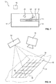
Bei einer weiteren Ausführungsform ist innerhalb des Kartenlesers eine Projektionseinheit zum Projizieren eines vorbestimmten Musters auf eine dem Transportweg zugewandte Seite eines den Transportweg begrenzenden Begrenzungselements des Kartenlesers vorgesehen, wobei das von der Bilderfassungseinheit aufgenommene Bild eine Abbildung zumindest eines Ausschnitts des projizierten Musters umfasst. Ist in dem Transportweg ein Skimmingmodul angeordnet, verändert dies die Struktur der Oberfläche, auf die das Muster projiziert wird, sodass sich die Abbildung des Musters in dem über die Bilderfassungseinheit aufgenommenen Bild verändert. Eine solche Veränderung kann über den Bildvergleich mit dem Soll-Bild auf einfach Weise erkannt werden, sodass ein Skimmingmodul zuverlässig detektiert werden kann.In a further embodiment, a projection unit for projecting a predetermined pattern onto a side of a limiting element of the card reader limiting the transport path is provided inside the card reader, the image captured by the image acquisition unit being an image of at least one detail of the projected pattern. If a skimming module is arranged in the transport path, this changes the structure of the surface onto which the pattern is projected, so that the image of the pattern changes in the image recorded via the image acquisition unit. Such a change can be easily detected via the image comparison with the target image, so that a skimming module can be reliably detected.
Das Muster ist insbesondere in Form eines Gitternetzes und/oder eines punktförmigen Musters ausgebildet. Ein solches Gitternetz ermöglicht eine besonders einfache Detektion von Objekten.The pattern is designed in particular in the form of a grid and / or a dot-shaped pattern. Such a grid allows a particularly simple detection of objects.
Die Steuereinheit bestimmt vorzugsweise in der Abbildung des Musters die Position von voreingestellten Elementen des Musters und vergleicht diese ermittelte Position mit einer Soll-Position des jeweiligen Elements in dem Soll-Bild. Auf diese Weise können Veränderungen zwischen dem Soll-Bild und der tatsächlichen Abbildung in dem aufgenommenen Bild erkannt werden und somit Skimmingmodule detektiert werden. Bei der Verwendung eines Gittermusters werden insbesondere die Positionen der Schnittpunkte der Gitterlinien ermittelt und mit Soll-Positionen verglichen.The control unit preferably determines the position of pre-set elements of the pattern in the image of the pattern and compares this determined position with a desired position of the respective element in the desired image. In this way, changes between the target image and the actual image in the captured image can be detected and thus skimming modules can be detected. When using a grid pattern, in particular the positions of the intersections of the grid lines are determined and compared with desired positions.
Bei einer weiteren Ausführungsform kann innerhalb des Kartenlesers eine Lichtquelle zum Aussenden von gepulstem Licht auf mindestens einem Teilbereich des Transportweges vorgesehen sein. Die Aufnahme des Bildes über die Bilderfassungseinheit ist mit dem gepulsten Licht synchronisiert, wobei das von der Bilderfassungseinheit aufgenommene Bild eine Abbildung zumindest eines Ausschnitts des durch das gepulste Licht beleuchteten Teilbereiches des Transportweges umfasst. Ein solches gepulstes, mit der Bildaufnahme synchronisiertes Licht ermöglicht es auf einfache Weise, dass Abstände innerhalb des Kartenlesers in dem aufgenommenen Bildern vermessen werden können, sodass über Vergleiche der Abstände mit vorbestimmten Soll-Abständen eingeschobene Skimmingmodule detektiert werden können.In a further embodiment, a light source for emitting pulsed light on at least a portion of the transport path can be provided within the card reader. The recording of the image via the image acquisition unit is synchronized with the pulsed light, the one of the Picture captured unit image comprises an image of at least a portion of the illuminated by the pulsed light portion of the transport path. Such a pulsed, synchronized with the image recording light makes it possible in a simple manner that distances can be measured within the card reader in the captured images, so skimmers inserted over comparisons of the distances with predetermined target intervals can be detected.
Die Bilderfassungseinheit ist insbesondere innerhalb des Kartenlesers angeordnet, sodass mit ihrer Hilfe auf einfache Weise der mit dem gepulsten Licht beleuchtete Teilbereich und/oder der Bereich, auf der das Muster projiziert wird, erfasst werden kann.The image acquisition unit is arranged in particular within the card reader, so that with its help in a simple way the illuminated with the pulsed light portion and / or the area on which the pattern is projected, can be detected.
Bei einer alternativen Ausführungsform kann die Bilderfassungseinheit auch außerhalb des Kartenlesers angeordnet sein. In diesem Fall ist mindestens eine optische Umlenkeinheit, beispielsweise ein Umlenkprisma, vorgesehen, mit dessen Hilfe der Erfassungsbereich der Bilderfassungseinheit in den Transportweg des Kartenlesers umgelenkt wird.In an alternative embodiment, the image capture unit can also be arranged outside the card reader. In this case, at least one optical deflection unit, for example a deflection prism, is provided, by means of which the detection area of the image detection unit is deflected into the transport path of the card reader.
Die Vorrichtung zum Lesen einer Magnetstreifen- und/oder Chipkarte, wie diese zuvor beschrieben ist, ist insbesondere in einem Geldautomaten, einem automatischen Kassensystem, einer automatischen Tresorkasse und/oder einen Bezahlterminal aufgenommen.The device for reading a magnetic stripe and / or chip card, as described above, is accommodated in particular in an ATM, an automatic POS system, an automatic cash deposit and / or a payment terminal.
Ferner umfasst die Vorrichtung vorzugsweise eine Informationsausgabeeinheit, mit deren Hilfe, wenn ein Skimmingmodul detektiert wurde, Informationen hierüber ausgegeben werden können. Auf diese Weise wird erreicht, dass zeitnah Gegenmaßnahmen eingeleitet werden können. Vorzugsweise ist die Vorrichtung über eine Datenübertragungsverbindung mit einer zentralen Recheneinheit verbunden, über die eine beauftragte Servicefirma und/oder Sicherheitskräfte informiert werden können. Darüber hinaus kann auch über eine Ausgabeeinheit, beispielsweise einem Bildschirm, der Vorrichtung einer entsprechenden Meldung an eine Bedienperson ausgegeben werden, sodass diese gewarnt ist und keine Magnetstreifen- und/oder Chipkarte in den Kartenleser einführt. Ferner kann das Einführen der Magnetstreifen- und/oder Chipkarte auch mechanisch unterbunden werden.Furthermore, the device preferably comprises an information output unit with the aid of which, when a skimming module has been detected, information about this can be output. In this way it is achieved that timely countermeasures can be initiated. Preferably, the device is connected via a data transmission connection to a central processing unit, via which a commissioned service company and / or security forces can be informed. In addition, the device of a corresponding message to an operator can also be output via an output unit, for example a screen, so that it is warned and does not insert a magnetic stripe and / or chip card into the card reader. Furthermore, the insertion of the magnetic stripe and / or chip card can also be prevented mechanically.
Weitere Merkmale und Vorteile der Erfindung ergeben sich aus der folgenden Beschreibung, die die Erfindung anhand von Ausführungsbeispielen im Zusammenhang mit den beigefügten Figuren näher erläutert.Further features and advantages of the invention will become apparent from the following description, which illustrates the invention with reference to embodiments in conjunction with the accompanying figures.
Es zeigen:
- Figur 1
- eine schematische Darstellung eines Geldautomaten;
- Figur 2
- eine schematische Darstellung einer Vorrichtung zum Lesen einer Magnetstreifen- und/oder Chipkarte gemäß einer ersten Ausführungsform;
- Figur 3
- eine Darstellung eines mit Hilfe der Kamera der Vorrichtung nach
Figur 2 aufgenommenen Bildes; - Figur 4
- eine Darstellung des Bildes nach
Figur 3 während der Bildverarbeitung; - Figur 5
- eine Darstellung eines weiteren mit Hilfe der Kamera nach
Figur 2 aufgenommenen Bildes ohne Skimmingmodul; - Figur 6
- eine Darstellung eines mit Hilfe der Kamera nach
Figur 2 aufgenommenen Bildes mit Skimmingmodul; - Figur 7
- eine schematische Darstellung einer Vorrichtung zum Lesen einer Magnetstreifen- oder Chipkarte gemäß einer zweiten Ausführungsform;
- Figur 8
- eine stark vereinfachte Darstellung der Funktionsweise der Vorrichtung nach
Figur 7 ; - Figur 9
- eine schematische Darstellung einer Vorrichtung zum Lesen einer Magnetstreifen- und/oder Chipkarte gemäß einer dritten Ausführungsform; und
Figur 10- eine schematische Darstellung einer Vorrichtung zum Lesen einer Magnetstreifen- und/oder Chipkarte gemäß einer vierten Ausführungsform.
- FIG. 1
- a schematic representation of an ATM;
- FIG. 2
- a schematic representation of an apparatus for reading a magnetic stripe and / or chip card according to a first embodiment;
- FIG. 3
- a representation of one with the help of the camera of the device according to
FIG. 2 recorded image; - FIG. 4
- a representation of the picture after
FIG. 3 during image processing; - FIG. 5
- a representation of another with the help of the camera
FIG. 2 recorded image without skimming module; - FIG. 6
- a representation of one with the help of the camera
FIG. 2 taken picture with skimming module; - FIG. 7
- a schematic representation of an apparatus for reading a magnetic stripe or smart card according to a second embodiment;
- FIG. 8
- a greatly simplified illustration of the operation of the device according to
FIG. 7 ; - FIG. 9
- a schematic representation of an apparatus for reading a magnetic stripe and / or chip card according to a third embodiment; and
- FIG. 10
- a schematic representation of an apparatus for reading a magnetic stripe and / or smart card according to a fourth embodiment.
In
Alternativ kann die Vorrichtung 10 zum Auslesen von Daten einer Magnetstreifen- und/oder Chipkarte auch in jeder anderen beliebigen Vorrichtung, insbesondere einem automatischen Kassensystem, einer automatischen Tresorkassen und/oder einem Bezahlterminals eingesetzt werden. Bei der Magnetstreifen und/oder Chipkarte handelt es sich insbesondere um eine EC-Karte, eine Kreditkarte und/oder eine Geldkarte.Alternatively, the
Bei neuartigen Skimmingangriffen wird über den Schlitz 12 in den Transportweg 14 des Kartenlesers 16 der Vorrichtung 10 ein Skimmingmodul eingeführt, mit dessen Hilfe die Daten einer eingeführten Magnetstreifen- und/oder Chipkarte ausgelesen werden können. Ferner wird, beispielsweise über eine verdeckt angebrachte Kamera und/oder ein auf Tastatur des Geldautomaten 100 angebrachten zusätzlichen Tastatur, die PIN, die zur Magnetkarten- und/oder Chipkarte gehört, ausgespäht, sodass eine den Skimmingangriff durchführende Person sowohl die Daten der Magnetstreifen- und/oder Chipkarte als auch die PIN kennt und somit unberechtigt Geld abheben kann und/oder Einkäufe tätigen kann.In the case of novel skimming attacks, a skimming module is introduced via the
Solche innerhalb des Transportweges 14, in dem normalerweise lediglich die Magnetstreifen- und/oder die Chipkarte während des Auslesens durch den Kartenleser und/oder bei Zuführen und/oder Entnehmen der Magnetstreifen- und/oder Chipkarte aufgenommen ist, aufgenommene Skimmingmodule können nicht durch bekannte Skimmingabwehrmaßnahmen, die darauf ausgelegt sind, Skimmingmodule, die vor dem Schlitz 12 angebracht sind, zu erkennen, detektiert werden. Um aber auch solche innerhalb des Transportweges 14 angeordneten Skimmingmodul detektieren zu können, werden die im Folgenden im Zusammenhang mit den
In
Die Steuereinheit 18 arbeitet insbesondere ein Bildverarbeitungsprogramm ab, mit dessen Hilfe das über die Kamera 20 aufgenommene Ist-Bild mit einem voreingestellten Soll-Bild des Lochmusters vergleicht. Über diesen Vergleich kann die Steuereinheit auf einfache Weise ermitteln, ob in dem Transportweg 14 ein Skimmingmodul eingeführt ist. Ist nämlich ein Skimmingmodul eingeführt, so ist mindestens eines der Löcher des Lochmusters verdeckt, sodass durch dieses kein Licht der Lichtquelle 26 hindurchtreten kann und dieses Loch entsprechend nicht in dem mit Hilfe der Kamera 20 aufgenommenen Bild abgebildet wird.In particular, the
Es ist besonders vorteilhaft, wenn die unterschiedlichen Vorrichtungen 10 jeweils unterschiedliche Lochmuster eingesetzt werden, sodass die die Skimmingangriffe durchführenden Personen die Form ihrer Skimmingmodule nicht an die Lochmuster anpassen können und somit Skimmingmodule zuverlässig detektiert werden können.It is particularly advantageous if the
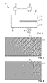
In
Bei einer alternativen Ausführungsform können zusätzlich oder alternativ zu den Lochmustern auch Teilbereiche der Begrenzungselemente 24 teiltransparent ausgebildet sein, sodass durch diese transparenten Bereiche hindurch ein Bild des Inneren des Kartenlesers, insbesondre des Transportweges 14, über die Kamera 20 aufgenommen werden kann.In an alternative embodiment, in addition to or as an alternative to the hole patterns, partial areas of the delimiting
In
Die Steuereinheit 10,führt insbesondere eine Segmentanalyse durch, bei der die mit Hilfe der Kamera 20 aufgenommenen Bilder in Segmente eingeteilt werden und diese Segmenten mit vorbestimmten Segmenten von gespeicherten Soll-Bildern verglichen werden. Zusätzlich oder alternativ kann auch eine Konturermittlung von aufgenommenen Objekten erfolgen und somit ein Vergleich von Konturen stattfinden. Zusätzlich oder alternativ können die ermittelten Objekte auch vermessen werden und/oder deren Position bestimmt werden. Über die entsprechenden gewonnenen Bildinformationen bei der Bildverarbeitung kann über den Vergleich zwischen dem aufgenommenen Ist-Bild und vorbestimmten Soll-Werten jeweils zuverlässig erkannt werden, ob ein Skimmingmodul bzw. ein andersartiges, nicht planmäßig vorgesehenes Objekt in dem Transportweg 14 angeordnet ist.The
In
Das Muster 54 ist bei dem in
Bei einer alternativen Ausführungsform kann auch jedes andere beliebige Muster projiziert werden, welches es ermöglicht, über die Bestimmung von Veränderungen des Musters in der durch die Kamera 20 ermittelten Abbildungen ein Objekt im Bereich des Musters 54 zu detektierten.In an alternative embodiment, any other arbitrary pattern can be projected, which makes it possible to detect an object in the region of the
In
In
Bei einer alternativen Ausführungsform der Erfindung können die einzelnen zuvor beschriebenen Ausführungsformen auch kombiniert werden. Durch das gleichzeitige Anwenden mehrere dieser Ausführungsformen kann die Sicherheit zur Detektion von Skimmingmodulen weiter erhöht werden. Außerdem können auch in verschiedene Teilbereiche des Transportweges parallel zueinander verschiedene der zuvor beschriebenen Ausführungsform angewandt werden.In an alternative embodiment of the invention, the individual embodiments described above can also be combined. By simultaneously applying several of these embodiments, the safety for the detection of skimming modules can be further increased. In addition, various different embodiments of the previously described embodiment can be used in different subregions of the transport path parallel to each other.
- 1010
- Vorrichtungcontraption
- 1212
- Schlitzslot
- 1414
- Transportwegtransport
- 1616
- Kartenlesercard reader
- 1818
- Steuereinheitcontrol unit
- 2020
- Kameracamera
- 2222
- Außenseiteoutside
- 26, 7026, 70
- Lichtquellelight source
- 30, 3230, 32
- DurchgangslochThrough Hole
- 4040
- Segmentsegment
- 5050
- Oberflächesurface
- 5252
- Projektionseinheitprojection unit
- 5454
- Mustertemplate
- 5656
- Netzliniepower line
- 5858
- Kreuzungspunktintersection
- 6060
- UmlenkeinheitReturn unit
- 6262
- Erfassungsbereichdetection range
- 100100
- GeldautomatATM
- 102102
- Geldkassettecashbox
- 104104
- Eingabe- und/oder AusgabeeinheitInput and / or output unit
- 106106
- Transportpfadtransport path
Claims (15)
mit einem Kartenleser (16) zum Auslesen von Daten aus der Magnetstreifen- und/der Chipkarte, der einem Transportweg (14) umfasst, entlang dessen die Magnetstreifen- und/oder Chipkarte beim Einführen in den Kartenleser (16) und/oder dem Entnehmen aus dem Kartenleser (16) bewegt wird und/oder in dem die Magnetstreifen- und/oder Chipkarte während des Auslesens aufgenommen ist,
und mit einer Bilderfassungseinheit (20) zur Aufnahme von Bildern des Kartenlesers (16),
dadurch gekennzeichnet, dass der Kartenleser (16) derart ausgebildet ist, dass mit Hilfe von durch die Bilderfassungseinheit (20) aufgenommenen Bildern detektierbar ist, ob im Transportweg (14) des Kartenlesers (16) ein Skimmingmodul zum Ausspähen von Daten von Magnetstreifen- und/oder Chipkarten aufgenommen ist.Device for reading a magnetic stripe and / or chip card,
with a card reader (16) for reading out data from the magnetic stripe and / or the chip card, which comprises a transport path (14), along which the magnetic stripe and / or chip card during insertion into the card reader (16) and / or the removal the card reader (16) is moved and / or in which the magnetic stripe and / or chip card is recorded during the reading,
and with an image acquisition unit (20) for receiving images of the card reader (16),
characterized in that the card reader (16) is designed such that it is detectable with the aid of images captured by the image acquisition unit (20) whether in the transport path (14) of the card reader (16) a skimming module for spying data from magnetic stripe and / or smart cards is recorded.
Priority Applications (7)
| Application Number | Priority Date | Filing Date | Title |
|---|---|---|---|
| EP12194205.6A EP2736026B1 (en) | 2012-11-26 | 2012-11-26 | Device for reading out a magnetic strip and/or chip card with a camera for detecting inserted skimming modules |
| BR112015009626-3A BR112015009626B1 (en) | 2012-11-26 | 2013-11-26 | DEVICE FOR READING A MAGNETIC STRIP AND/OR CHIP CARD WITH A CARD READER |
| US14/647,301 US9754462B2 (en) | 2012-11-26 | 2013-11-26 | Device for reading a magnetic stripe and/or chip card having a camera for the detection of inserted skimming modules |
| EA201591034A EA201591034A1 (en) | 2012-11-26 | 2013-11-26 | DEVICE FOR READING A CARD WITH A MAGNETIC STRIP AND / OR CHIP CARD CONTAINING A CAMERA FOR DETECTING AN EXTENDED SCIMMING MODULES |
| PCT/EP2013/074706 WO2014080031A1 (en) | 2012-11-26 | 2013-11-26 | Device for reading a magnetic strip and/or chip card, comprising a camera for detecting inserted skimming modules |
| CN201380060551.0A CN104798117B (en) | 2012-11-26 | 2013-11-26 | With for detecting that the magnetic stripe card and/or chip card of inserting the camera for surveying record module read equipment |
| US15/695,695 US10748387B2 (en) | 2012-11-26 | 2017-09-05 | Device for reading a magnetic stripe and/or chip card having a camera for the detection of inserted skimming modules |
Applications Claiming Priority (1)
| Application Number | Priority Date | Filing Date | Title |
|---|---|---|---|
| EP12194205.6A EP2736026B1 (en) | 2012-11-26 | 2012-11-26 | Device for reading out a magnetic strip and/or chip card with a camera for detecting inserted skimming modules |
Publications (2)
| Publication Number | Publication Date |
|---|---|
| EP2736026A1 true EP2736026A1 (en) | 2014-05-28 |
| EP2736026B1 EP2736026B1 (en) | 2020-03-25 |
Family
ID=47471500
Family Applications (1)
| Application Number | Title | Priority Date | Filing Date |
|---|---|---|---|
| EP12194205.6A Active EP2736026B1 (en) | 2012-11-26 | 2012-11-26 | Device for reading out a magnetic strip and/or chip card with a camera for detecting inserted skimming modules |
Country Status (6)
| Country | Link |
|---|---|
| US (2) | US9754462B2 (en) |
| EP (1) | EP2736026B1 (en) |
| CN (1) | CN104798117B (en) |
| BR (1) | BR112015009626B1 (en) |
| EA (1) | EA201591034A1 (en) |
| WO (1) | WO2014080031A1 (en) |
Cited By (1)
| Publication number | Priority date | Publication date | Assignee | Title |
|---|---|---|---|---|
| US11610457B2 (en) | 2020-11-03 | 2023-03-21 | Bank Of America Corporation | Detecting unauthorized activity related to a computer peripheral device by monitoring voltage of the peripheral device |
Families Citing this family (11)
| Publication number | Priority date | Publication date | Assignee | Title |
|---|---|---|---|---|
| US9818049B2 (en) * | 2011-12-08 | 2017-11-14 | Tmd Holding B.V. | Anti skimming and anti shimming card feed unit, kernel element, read out unit, transaction machine and method |
| WO2015116576A1 (en) * | 2014-01-28 | 2015-08-06 | Capital One Financial Corporation | Detection of unauthorized devices on atms |
| US10262326B1 (en) | 2017-07-31 | 2019-04-16 | Wells Fargo Bank, N.A. | Anti-skimming card reader computing device |
| CN108898756A (en) * | 2018-05-04 | 2018-11-27 | 深圳怡化电脑股份有限公司 | A kind of security processing of business, system and financial terminal |
| US10599964B1 (en) | 2019-01-15 | 2020-03-24 | Capital One Services, Llc | System and method for transmitting financial information via color matrix code |
| US10628638B1 (en) * | 2019-03-22 | 2020-04-21 | Capital One Services, Llc | Techniques to automatically detect fraud devices |
| CN111581144B (en) * | 2020-03-24 | 2022-02-08 | 惠州市德赛西威智能交通技术研究院有限公司 | Vehicle-mounted camera hot-plug self-recovery method and device and storage medium |
| US20220114351A1 (en) * | 2020-10-14 | 2022-04-14 | Ncr Corporation | System and method for detecting a smart card |
| US11875652B2 (en) | 2021-10-22 | 2024-01-16 | Kyndryl, Inc. | Card skimming detection |
| JP2024025145A (en) * | 2022-08-10 | 2024-02-26 | ニデックインスツルメンツ株式会社 | Foreign object detection device, card reader, foreign object detection method, and foreign object detection program |
| US11790189B1 (en) * | 2022-08-31 | 2023-10-17 | Ncr Corporation | System and method for detecting a foreign object |
Citations (9)
| Publication number | Priority date | Publication date | Assignee | Title |
|---|---|---|---|---|
| JPS60220808A (en) * | 1984-04-17 | 1985-11-05 | Inax Corp | Surface inspecting method |
| JPH08313222A (en) * | 1995-05-24 | 1996-11-29 | Matsushita Electric Ind Co Ltd | Method of inspecting transparent body |
| US20090201372A1 (en) * | 2006-02-13 | 2009-08-13 | Fraudhalt, Ltd. | Method and apparatus for integrated atm surveillance |
| DE102009018322A1 (en) | 2009-04-22 | 2010-10-28 | Wincor Nixdorf International Gmbh | Self-service terminal with camera for detecting tampering attempts |
| DE102009018319A1 (en) * | 2009-04-22 | 2010-10-28 | Wincor Nixdorf International Gmbh | Self-service terminal with at least one camera for detecting tampering attempts |
| DE102009018320A1 (en) | 2009-04-22 | 2010-10-28 | Wincor Nixdorf International Gmbh | A method of detecting tampering attempts at a self-service terminal and data processing unit therefor |
| DE102010036961A1 (en) | 2010-08-12 | 2012-02-16 | Wincor Nixdorf International Gmbh | Method and device for detecting and verifying manipulation attempts on a self-service terminal |
| DE102011010737A1 (en) | 2011-02-09 | 2012-08-09 | Stephan Maaß | Method for improving manipulation protection of automated teller machine, involves allowing user to check keyboard and/or insertion opening on changes relative to unmanipulated ATM before insertion of identification card |
| DE102011001541A1 (en) | 2011-03-24 | 2012-09-27 | Wincor Nixdorf International Gmbh | Self-service terminal and method for monitoring a user location area |
Family Cites Families (19)
| Publication number | Priority date | Publication date | Assignee | Title |
|---|---|---|---|---|
| US8640947B1 (en) * | 2002-11-26 | 2014-02-04 | Diebold Self-Service Systems, Division Of Diebold, Incorporated | Automated banking machine operated responsive to data bearing records with improved resistance to fraud |
| WO2005109315A2 (en) * | 2004-04-30 | 2005-11-17 | Utc Fire & Safety Corp. | Atm security system |
| US7458516B2 (en) * | 2005-11-14 | 2008-12-02 | Ncr Corporation | Card reader |
| US7648076B2 (en) * | 2005-11-21 | 2010-01-19 | Jds Uniphase Corporation | Magnetic tape with holographic hidden pattern, method of making same and reader for reading same |
| US20070200928A1 (en) * | 2006-02-13 | 2007-08-30 | O'doherty Phelim A | Method and apparatus for automated video surveillance |
| KR100863744B1 (en) | 2006-06-15 | 2008-10-16 | 노틸러스효성 주식회사 | PINPAD for preventing outflow of client's information in an ATM and method for operating the same |
| JP2008027259A (en) * | 2006-07-24 | 2008-02-07 | Hitachi Omron Terminal Solutions Corp | Suspicious object or shape change detecting system |
| US7354003B1 (en) * | 2006-09-15 | 2008-04-08 | Ncr Corporation | Card reader |
| CN101276499B (en) * | 2008-04-18 | 2010-09-01 | 浙江工业大学 | Intelligent monitoring apparatus of ATM equipment based on all-directional computer vision |
| US9147324B2 (en) * | 2009-02-23 | 2015-09-29 | Honeywell International Inc. | System and method to detect tampering at ATM machines |
| DE102009018318A1 (en) * | 2009-04-22 | 2010-10-28 | Wincor Nixdorf International Gmbh | Self-service terminal with at least one image data-generating camera for detecting tampering attempts |
| US8736199B2 (en) * | 2010-04-13 | 2014-05-27 | John M. J. Madey | Temperature stabilized microwave electron gun |
| CN201965699U (en) * | 2011-01-14 | 2011-09-07 | 由田新技股份有限公司 | ATM (Automatic Teller Machine) monitoring device |
| US8633969B2 (en) * | 2011-02-09 | 2014-01-21 | Omnivision Technologies, Inc. | Apparatus and method for three-dimensional image capture with extended depth of field |
| DE102011011541A1 (en) | 2011-02-17 | 2012-08-23 | Fraunhofer-Gesellschaft zur Förderung der angewandten Forschung e.V. | Ultrasonic transducer arrangement, has concave reflector surface whose focus region lies in subsequent semi-infinite space rear to ultrasonic transducer that turns transducer surface, and reflecting body provided with reflector surface |
| GB2488538B (en) * | 2011-02-22 | 2017-02-22 | Atm Parts Company Ltd | Apparatus and method for monitoring a card slot |
| US8523072B2 (en) * | 2011-12-13 | 2013-09-03 | Parabit Systems, Inc. | Card reader protection system |
| US9767422B2 (en) * | 2013-03-12 | 2017-09-19 | Diebold Self-Service Systems, Division Of Diebold, Incorporated | Detecting unauthorized card skimmers |
| KR101797118B1 (en) * | 2016-05-09 | 2017-11-14 | 한국과학기술연구원 | Single pulse laser apparatus |
-
2012
- 2012-11-26 EP EP12194205.6A patent/EP2736026B1/en active Active
-
2013
- 2013-11-26 CN CN201380060551.0A patent/CN104798117B/en active Active
- 2013-11-26 US US14/647,301 patent/US9754462B2/en active Active
- 2013-11-26 BR BR112015009626-3A patent/BR112015009626B1/en active IP Right Grant
- 2013-11-26 EA EA201591034A patent/EA201591034A1/en unknown
- 2013-11-26 WO PCT/EP2013/074706 patent/WO2014080031A1/en active Application Filing
-
2017
- 2017-09-05 US US15/695,695 patent/US10748387B2/en active Active
Patent Citations (9)
| Publication number | Priority date | Publication date | Assignee | Title |
|---|---|---|---|---|
| JPS60220808A (en) * | 1984-04-17 | 1985-11-05 | Inax Corp | Surface inspecting method |
| JPH08313222A (en) * | 1995-05-24 | 1996-11-29 | Matsushita Electric Ind Co Ltd | Method of inspecting transparent body |
| US20090201372A1 (en) * | 2006-02-13 | 2009-08-13 | Fraudhalt, Ltd. | Method and apparatus for integrated atm surveillance |
| DE102009018322A1 (en) | 2009-04-22 | 2010-10-28 | Wincor Nixdorf International Gmbh | Self-service terminal with camera for detecting tampering attempts |
| DE102009018319A1 (en) * | 2009-04-22 | 2010-10-28 | Wincor Nixdorf International Gmbh | Self-service terminal with at least one camera for detecting tampering attempts |
| DE102009018320A1 (en) | 2009-04-22 | 2010-10-28 | Wincor Nixdorf International Gmbh | A method of detecting tampering attempts at a self-service terminal and data processing unit therefor |
| DE102010036961A1 (en) | 2010-08-12 | 2012-02-16 | Wincor Nixdorf International Gmbh | Method and device for detecting and verifying manipulation attempts on a self-service terminal |
| DE102011010737A1 (en) | 2011-02-09 | 2012-08-09 | Stephan Maaß | Method for improving manipulation protection of automated teller machine, involves allowing user to check keyboard and/or insertion opening on changes relative to unmanipulated ATM before insertion of identification card |
| DE102011001541A1 (en) | 2011-03-24 | 2012-09-27 | Wincor Nixdorf International Gmbh | Self-service terminal and method for monitoring a user location area |
Cited By (1)
| Publication number | Priority date | Publication date | Assignee | Title |
|---|---|---|---|---|
| US11610457B2 (en) | 2020-11-03 | 2023-03-21 | Bank Of America Corporation | Detecting unauthorized activity related to a computer peripheral device by monitoring voltage of the peripheral device |
Also Published As
| Publication number | Publication date |
|---|---|
| BR112015009626B1 (en) | 2021-11-16 |
| CN104798117A (en) | 2015-07-22 |
| US20180040206A1 (en) | 2018-02-08 |
| CN104798117B (en) | 2017-08-29 |
| WO2014080031A1 (en) | 2014-05-30 |
| US10748387B2 (en) | 2020-08-18 |
| BR112015009626A2 (en) | 2017-07-04 |
| US20150302707A1 (en) | 2015-10-22 |
| EP2736026B1 (en) | 2020-03-25 |
| US9754462B2 (en) | 2017-09-05 |
| EA201591034A1 (en) | 2015-09-30 |
Similar Documents
| Publication | Publication Date | Title |
|---|---|---|
| EP2736026B1 (en) | Device for reading out a magnetic strip and/or chip card with a camera for detecting inserted skimming modules | |
| EP1307855B1 (en) | Reader device with bar-coded authorisation cards | |
| DE2935668C2 (en) | ||
| EP2897112B1 (en) | Method and apparatus for the prevention of false alarms in monitoring systems | |
| AT4894U1 (en) | DEVICE FOR PROTECTING SELF-MACHINES AGAINST MANIPULATIONS | |
| DE102010055974A1 (en) | Method and device for determining a class reference data set for the classification of value documents | |
| EP2797057B1 (en) | Device for reading magnetic strip and/or chip cards and method for avoiding skimming attacks | |
| WO2010043358A1 (en) | Method and device for processing value documents | |
| EP2722788B1 (en) | Apparatus for reading a chip card and method for detecting a skimming module | |
| EP3357043B1 (en) | Document and process for verifying a document | |
| DE102005052671A1 (en) | Monetary value document e.g. voucher, checking method for use in e.g. bank, involves detecting distinguishing characteristic of document by high resolution camera and evaluating characteristic for authenticity of document | |
| DE10132589B4 (en) | Method for qualitative assessment of material | |
| EP2897108B1 (en) | Test unit for detecting skimming modules | |
| EP3142039B1 (en) | Self-service terminal with card reader and method for monitoring | |
| DE102015115172A1 (en) | Method and device for determining the integrity of a card reading device and a self-service terminal equipped therewith | |
| DE202005018964U1 (en) | Document validity checking device, e.g. for driving licenses, checks or credit cards, has at least two light sources, so that document being checked can be imaged when illuminated from several different angles | |
| DE102005009332A1 (en) | Bank note separation checking method, involves completing separation of bank note on existence of note, if consistency between two portraits is high, and completing separation during lower consistency on existence of more than one note | |
| EP3896663A1 (en) | Self-service machine | |
| EP2920769B1 (en) | Apparatus and method to evaluate valuable documents | |
| EP3563356B1 (en) | Method and device for detecting a security thread in a value document | |
| DE202011105565U1 (en) | test card | |
| EP2422324B1 (en) | Automated teller machine comprising camera arrangement to detect manipulation attempts | |
| DE102022124736B3 (en) | Gate arrangement, especially for a passenger transport system | |
| DE102016015545A1 (en) | Method and device for detecting a security thread in a value document | |
| EP2338130B1 (en) | Method for automatic optical character recognition, computer program product, data processing system, and scanner |
Legal Events
| Date | Code | Title | Description |
|---|---|---|---|
| PUAI | Public reference made under article 153(3) epc to a published international application that has entered the european phase |
Free format text: ORIGINAL CODE: 0009012 |
|
| 17P | Request for examination filed |
Effective date: 20121126 |
|
| AK | Designated contracting states |
Kind code of ref document: A1 Designated state(s): AL AT BE BG CH CY CZ DE DK EE ES FI FR GB GR HR HU IE IS IT LI LT LU LV MC MK MT NL NO PL PT RO RS SE SI SK SM TR |
|
| AX | Request for extension of the european patent |
Extension state: BA ME |
|
| R17P | Request for examination filed (corrected) |
Effective date: 20141113 |
|
| RBV | Designated contracting states (corrected) |
Designated state(s): AL AT BE BG CH CY CZ DE DK EE ES FI FR GB GR HR HU IE IS IT LI LT LU LV MC MK MT NL NO PL PT RO RS SE SI SK SM TR |
|
| STAA | Information on the status of an ep patent application or granted ep patent |
Free format text: STATUS: EXAMINATION IS IN PROGRESS |
|
| 17Q | First examination report despatched |
Effective date: 20181029 |
|
| RIN1 | Information on inventor provided before grant (corrected) |
Inventor name: DRICHEL, ALEXANDER Inventor name: SCHLIEBE, DIETER Inventor name: WIESINGER, TORSTEN Inventor name: PRIESTERJAHN, STEFFEN |
|
| GRAP | Despatch of communication of intention to grant a patent |
Free format text: ORIGINAL CODE: EPIDOSNIGR1 |
|
| STAA | Information on the status of an ep patent application or granted ep patent |
Free format text: STATUS: GRANT OF PATENT IS INTENDED |
|
| INTG | Intention to grant announced |
Effective date: 20191023 |
|
| GRAS | Grant fee paid |
Free format text: ORIGINAL CODE: EPIDOSNIGR3 |
|
| GRAA | (expected) grant |
Free format text: ORIGINAL CODE: 0009210 |
|
| STAA | Information on the status of an ep patent application or granted ep patent |
Free format text: STATUS: THE PATENT HAS BEEN GRANTED |
|
| AK | Designated contracting states |
Kind code of ref document: B1 Designated state(s): AL AT BE BG CH CY CZ DE DK EE ES FI FR GB GR HR HU IE IS IT LI LT LU LV MC MK MT NL NO PL PT RO RS SE SI SK SM TR |
|
| REG | Reference to a national code |
Ref country code: GB Ref legal event code: FG4D Free format text: NOT ENGLISH |
|
| RIN1 | Information on inventor provided before grant (corrected) |
Inventor name: SCHLIEBE, DIETER Inventor name: DRICHEL, ALEXANDER Inventor name: WIESINGER, TORSTEN Inventor name: PRIESTERJAHN, STEFFEN |
|
| REG | Reference to a national code |
Ref country code: DE Ref legal event code: R096 Ref document number: 502012015892 Country of ref document: DE |
|
| REG | Reference to a national code |
Ref country code: AT Ref legal event code: REF Ref document number: 1249459 Country of ref document: AT Kind code of ref document: T Effective date: 20200415 Ref country code: IE Ref legal event code: FG4D Free format text: LANGUAGE OF EP DOCUMENT: GERMAN |
|
| PG25 | Lapsed in a contracting state [announced via postgrant information from national office to epo] |
Ref country code: RS Free format text: LAPSE BECAUSE OF FAILURE TO SUBMIT A TRANSLATION OF THE DESCRIPTION OR TO PAY THE FEE WITHIN THE PRESCRIBED TIME-LIMIT Effective date: 20200325 Ref country code: FI Free format text: LAPSE BECAUSE OF FAILURE TO SUBMIT A TRANSLATION OF THE DESCRIPTION OR TO PAY THE FEE WITHIN THE PRESCRIBED TIME-LIMIT Effective date: 20200325 Ref country code: NO Free format text: LAPSE BECAUSE OF FAILURE TO SUBMIT A TRANSLATION OF THE DESCRIPTION OR TO PAY THE FEE WITHIN THE PRESCRIBED TIME-LIMIT Effective date: 20200625 |
|
| PG25 | Lapsed in a contracting state [announced via postgrant information from national office to epo] |
Ref country code: HR Free format text: LAPSE BECAUSE OF FAILURE TO SUBMIT A TRANSLATION OF THE DESCRIPTION OR TO PAY THE FEE WITHIN THE PRESCRIBED TIME-LIMIT Effective date: 20200325 Ref country code: SE Free format text: LAPSE BECAUSE OF FAILURE TO SUBMIT A TRANSLATION OF THE DESCRIPTION OR TO PAY THE FEE WITHIN THE PRESCRIBED TIME-LIMIT Effective date: 20200325 Ref country code: LV Free format text: LAPSE BECAUSE OF FAILURE TO SUBMIT A TRANSLATION OF THE DESCRIPTION OR TO PAY THE FEE WITHIN THE PRESCRIBED TIME-LIMIT Effective date: 20200325 Ref country code: GR Free format text: LAPSE BECAUSE OF FAILURE TO SUBMIT A TRANSLATION OF THE DESCRIPTION OR TO PAY THE FEE WITHIN THE PRESCRIBED TIME-LIMIT Effective date: 20200626 Ref country code: BG Free format text: LAPSE BECAUSE OF FAILURE TO SUBMIT A TRANSLATION OF THE DESCRIPTION OR TO PAY THE FEE WITHIN THE PRESCRIBED TIME-LIMIT Effective date: 20200625 |
|
| REG | Reference to a national code |
Ref country code: NL Ref legal event code: MP Effective date: 20200325 |
|
| REG | Reference to a national code |
Ref country code: LT Ref legal event code: MG4D |
|
| PG25 | Lapsed in a contracting state [announced via postgrant information from national office to epo] |
Ref country code: NL Free format text: LAPSE BECAUSE OF FAILURE TO SUBMIT A TRANSLATION OF THE DESCRIPTION OR TO PAY THE FEE WITHIN THE PRESCRIBED TIME-LIMIT Effective date: 20200325 |
|
| PG25 | Lapsed in a contracting state [announced via postgrant information from national office to epo] |
Ref country code: IS Free format text: LAPSE BECAUSE OF FAILURE TO SUBMIT A TRANSLATION OF THE DESCRIPTION OR TO PAY THE FEE WITHIN THE PRESCRIBED TIME-LIMIT Effective date: 20200725 Ref country code: RO Free format text: LAPSE BECAUSE OF FAILURE TO SUBMIT A TRANSLATION OF THE DESCRIPTION OR TO PAY THE FEE WITHIN THE PRESCRIBED TIME-LIMIT Effective date: 20200325 Ref country code: CZ Free format text: LAPSE BECAUSE OF FAILURE TO SUBMIT A TRANSLATION OF THE DESCRIPTION OR TO PAY THE FEE WITHIN THE PRESCRIBED TIME-LIMIT Effective date: 20200325 Ref country code: SK Free format text: LAPSE BECAUSE OF FAILURE TO SUBMIT A TRANSLATION OF THE DESCRIPTION OR TO PAY THE FEE WITHIN THE PRESCRIBED TIME-LIMIT Effective date: 20200325 Ref country code: LT Free format text: LAPSE BECAUSE OF FAILURE TO SUBMIT A TRANSLATION OF THE DESCRIPTION OR TO PAY THE FEE WITHIN THE PRESCRIBED TIME-LIMIT Effective date: 20200325 Ref country code: PT Free format text: LAPSE BECAUSE OF FAILURE TO SUBMIT A TRANSLATION OF THE DESCRIPTION OR TO PAY THE FEE WITHIN THE PRESCRIBED TIME-LIMIT Effective date: 20200818 Ref country code: EE Free format text: LAPSE BECAUSE OF FAILURE TO SUBMIT A TRANSLATION OF THE DESCRIPTION OR TO PAY THE FEE WITHIN THE PRESCRIBED TIME-LIMIT Effective date: 20200325 Ref country code: SM Free format text: LAPSE BECAUSE OF FAILURE TO SUBMIT A TRANSLATION OF THE DESCRIPTION OR TO PAY THE FEE WITHIN THE PRESCRIBED TIME-LIMIT Effective date: 20200325 |
|
| REG | Reference to a national code |
Ref country code: DE Ref legal event code: R097 Ref document number: 502012015892 Country of ref document: DE |
|
| PG25 | Lapsed in a contracting state [announced via postgrant information from national office to epo] |
Ref country code: DK Free format text: LAPSE BECAUSE OF FAILURE TO SUBMIT A TRANSLATION OF THE DESCRIPTION OR TO PAY THE FEE WITHIN THE PRESCRIBED TIME-LIMIT Effective date: 20200325 Ref country code: ES Free format text: LAPSE BECAUSE OF FAILURE TO SUBMIT A TRANSLATION OF THE DESCRIPTION OR TO PAY THE FEE WITHIN THE PRESCRIBED TIME-LIMIT Effective date: 20200325 Ref country code: IT Free format text: LAPSE BECAUSE OF FAILURE TO SUBMIT A TRANSLATION OF THE DESCRIPTION OR TO PAY THE FEE WITHIN THE PRESCRIBED TIME-LIMIT Effective date: 20200325 |
|
| PLBE | No opposition filed within time limit |
Free format text: ORIGINAL CODE: 0009261 |
|
| STAA | Information on the status of an ep patent application or granted ep patent |
Free format text: STATUS: NO OPPOSITION FILED WITHIN TIME LIMIT |
|
| PG25 | Lapsed in a contracting state [announced via postgrant information from national office to epo] |
Ref country code: PL Free format text: LAPSE BECAUSE OF FAILURE TO SUBMIT A TRANSLATION OF THE DESCRIPTION OR TO PAY THE FEE WITHIN THE PRESCRIBED TIME-LIMIT Effective date: 20200325 |
|
| 26N | No opposition filed |
Effective date: 20210112 |
|
| PG25 | Lapsed in a contracting state [announced via postgrant information from national office to epo] |
Ref country code: SI Free format text: LAPSE BECAUSE OF FAILURE TO SUBMIT A TRANSLATION OF THE DESCRIPTION OR TO PAY THE FEE WITHIN THE PRESCRIBED TIME-LIMIT Effective date: 20200325 |
|
| PG25 | Lapsed in a contracting state [announced via postgrant information from national office to epo] |
Ref country code: MC Free format text: LAPSE BECAUSE OF FAILURE TO SUBMIT A TRANSLATION OF THE DESCRIPTION OR TO PAY THE FEE WITHIN THE PRESCRIBED TIME-LIMIT Effective date: 20200325 |
|
| REG | Reference to a national code |
Ref country code: CH Ref legal event code: PL |
|
| PG25 | Lapsed in a contracting state [announced via postgrant information from national office to epo] |
Ref country code: LU Free format text: LAPSE BECAUSE OF NON-PAYMENT OF DUE FEES Effective date: 20201126 |
|
| REG | Reference to a national code |
Ref country code: BE Ref legal event code: MM Effective date: 20201130 |
|
| PG25 | Lapsed in a contracting state [announced via postgrant information from national office to epo] |
Ref country code: LI Free format text: LAPSE BECAUSE OF NON-PAYMENT OF DUE FEES Effective date: 20201130 Ref country code: CH Free format text: LAPSE BECAUSE OF NON-PAYMENT OF DUE FEES Effective date: 20201130 |
|
| PG25 | Lapsed in a contracting state [announced via postgrant information from national office to epo] |
Ref country code: IE Free format text: LAPSE BECAUSE OF NON-PAYMENT OF DUE FEES Effective date: 20201126 |
|
| REG | Reference to a national code |
Ref country code: AT Ref legal event code: MM01 Ref document number: 1249459 Country of ref document: AT Kind code of ref document: T Effective date: 20201126 |
|
| PG25 | Lapsed in a contracting state [announced via postgrant information from national office to epo] |
Ref country code: AT Free format text: LAPSE BECAUSE OF NON-PAYMENT OF DUE FEES Effective date: 20201126 |
|
| PG25 | Lapsed in a contracting state [announced via postgrant information from national office to epo] |
Ref country code: TR Free format text: LAPSE BECAUSE OF FAILURE TO SUBMIT A TRANSLATION OF THE DESCRIPTION OR TO PAY THE FEE WITHIN THE PRESCRIBED TIME-LIMIT Effective date: 20200325 Ref country code: MT Free format text: LAPSE BECAUSE OF FAILURE TO SUBMIT A TRANSLATION OF THE DESCRIPTION OR TO PAY THE FEE WITHIN THE PRESCRIBED TIME-LIMIT Effective date: 20200325 Ref country code: CY Free format text: LAPSE BECAUSE OF FAILURE TO SUBMIT A TRANSLATION OF THE DESCRIPTION OR TO PAY THE FEE WITHIN THE PRESCRIBED TIME-LIMIT Effective date: 20200325 |
|
| PG25 | Lapsed in a contracting state [announced via postgrant information from national office to epo] |
Ref country code: MK Free format text: LAPSE BECAUSE OF FAILURE TO SUBMIT A TRANSLATION OF THE DESCRIPTION OR TO PAY THE FEE WITHIN THE PRESCRIBED TIME-LIMIT Effective date: 20200325 Ref country code: AL Free format text: LAPSE BECAUSE OF FAILURE TO SUBMIT A TRANSLATION OF THE DESCRIPTION OR TO PAY THE FEE WITHIN THE PRESCRIBED TIME-LIMIT Effective date: 20200325 |
|
| PG25 | Lapsed in a contracting state [announced via postgrant information from national office to epo] |
Ref country code: BE Free format text: LAPSE BECAUSE OF NON-PAYMENT OF DUE FEES Effective date: 20201130 |
|
| REG | Reference to a national code |
Ref country code: FR Ref legal event code: PLFP Year of fee payment: 11 |
|
| REG | Reference to a national code |
Ref country code: GB Ref legal event code: 732E Free format text: REGISTERED BETWEEN 20230323 AND 20230329 |
|
| REG | Reference to a national code |
Ref country code: GB Ref legal event code: 732E Free format text: REGISTERED BETWEEN 20230525 AND 20230601 |
|
| REG | Reference to a national code |
Ref country code: DE Ref legal event code: R081 Ref document number: 502012015892 Country of ref document: DE Owner name: DIEBOLD NIXDORF SYSTEMS GMBH, DE Free format text: FORMER OWNER: WINCOR NIXDORF INTERNATIONAL GMBH, 33106 PADERBORN, DE |
|
| PGFP | Annual fee paid to national office [announced via postgrant information from national office to epo] |
Ref country code: GB Payment date: 20231019 Year of fee payment: 12 |
|
| PGFP | Annual fee paid to national office [announced via postgrant information from national office to epo] |
Ref country code: FR Payment date: 20231019 Year of fee payment: 12 Ref country code: DE Payment date: 20231019 Year of fee payment: 12 |