EP2735809B1 - Überwachungssystem und Verfahren zur Überwachung und Einstellung von Luftparametern in einem Raum, Dunstabzugsvorrichtung zur Verwendung in einem Überwachungssystem - Google Patents
Überwachungssystem und Verfahren zur Überwachung und Einstellung von Luftparametern in einem Raum, Dunstabzugsvorrichtung zur Verwendung in einem Überwachungssystem Download PDFInfo
- Publication number
- EP2735809B1 EP2735809B1 EP13190109.2A EP13190109A EP2735809B1 EP 2735809 B1 EP2735809 B1 EP 2735809B1 EP 13190109 A EP13190109 A EP 13190109A EP 2735809 B1 EP2735809 B1 EP 2735809B1
- Authority
- EP
- European Patent Office
- Prior art keywords
- sensor
- monitoring
- air
- monitoring system
- unit
- Prior art date
- Legal status (The legal status is an assumption and is not a legal conclusion. Google has not performed a legal analysis and makes no representation as to the accuracy of the status listed.)
- Active
Links
Images

Classifications
-
- G—PHYSICS
- G01—MEASURING; TESTING
- G01N—INVESTIGATING OR ANALYSING MATERIALS BY DETERMINING THEIR CHEMICAL OR PHYSICAL PROPERTIES
- G01N1/00—Sampling; Preparing specimens for investigation
- G01N1/02—Devices for withdrawing samples
- G01N1/22—Devices for withdrawing samples in the gaseous state
- G01N1/2273—Atmospheric sampling
-
- F—MECHANICAL ENGINEERING; LIGHTING; HEATING; WEAPONS; BLASTING
- F24—HEATING; RANGES; VENTILATING
- F24C—DOMESTIC STOVES OR RANGES ; DETAILS OF DOMESTIC STOVES OR RANGES, OF GENERAL APPLICATION
- F24C15/00—Details
- F24C15/20—Removing cooking fumes
-
- F—MECHANICAL ENGINEERING; LIGHTING; HEATING; WEAPONS; BLASTING
- F24—HEATING; RANGES; VENTILATING
- F24F—AIR-CONDITIONING; AIR-HUMIDIFICATION; VENTILATION; USE OF AIR CURRENTS FOR SCREENING
- F24F11/00—Control or safety arrangements
- F24F11/0001—Control or safety arrangements for ventilation
-
- F—MECHANICAL ENGINEERING; LIGHTING; HEATING; WEAPONS; BLASTING
- F24—HEATING; RANGES; VENTILATING
- F24F—AIR-CONDITIONING; AIR-HUMIDIFICATION; VENTILATION; USE OF AIR CURRENTS FOR SCREENING
- F24F11/00—Control or safety arrangements
- F24F11/30—Control or safety arrangements for purposes related to the operation of the system, e.g. for safety or monitoring
-
- F—MECHANICAL ENGINEERING; LIGHTING; HEATING; WEAPONS; BLASTING
- F24—HEATING; RANGES; VENTILATING
- F24F—AIR-CONDITIONING; AIR-HUMIDIFICATION; VENTILATION; USE OF AIR CURRENTS FOR SCREENING
- F24F11/00—Control or safety arrangements
- F24F11/50—Control or safety arrangements characterised by user interfaces or communication
- F24F11/52—Indication arrangements, e.g. displays
-
- F—MECHANICAL ENGINEERING; LIGHTING; HEATING; WEAPONS; BLASTING
- F24—HEATING; RANGES; VENTILATING
- F24F—AIR-CONDITIONING; AIR-HUMIDIFICATION; VENTILATION; USE OF AIR CURRENTS FOR SCREENING
- F24F11/00—Control or safety arrangements
- F24F11/50—Control or safety arrangements characterised by user interfaces or communication
- F24F11/56—Remote control
- F24F11/58—Remote control using Internet communication
-
- F—MECHANICAL ENGINEERING; LIGHTING; HEATING; WEAPONS; BLASTING
- F24—HEATING; RANGES; VENTILATING
- F24F—AIR-CONDITIONING; AIR-HUMIDIFICATION; VENTILATION; USE OF AIR CURRENTS FOR SCREENING
- F24F11/00—Control or safety arrangements
- F24F11/62—Control or safety arrangements characterised by the type of control or by internal processing, e.g. using fuzzy logic, adaptive control or estimation of values
- F24F11/63—Electronic processing
-
- F—MECHANICAL ENGINEERING; LIGHTING; HEATING; WEAPONS; BLASTING
- F24—HEATING; RANGES; VENTILATING
- F24C—DOMESTIC STOVES OR RANGES ; DETAILS OF DOMESTIC STOVES OR RANGES, OF GENERAL APPLICATION
- F24C15/00—Details
- F24C15/20—Removing cooking fumes
- F24C15/2021—Arrangement or mounting of control or safety systems
-
- F—MECHANICAL ENGINEERING; LIGHTING; HEATING; WEAPONS; BLASTING
- F24—HEATING; RANGES; VENTILATING
- F24F—AIR-CONDITIONING; AIR-HUMIDIFICATION; VENTILATION; USE OF AIR CURRENTS FOR SCREENING
- F24F11/00—Control or safety arrangements
- F24F11/50—Control or safety arrangements characterised by user interfaces or communication
- F24F11/56—Remote control
-
- F—MECHANICAL ENGINEERING; LIGHTING; HEATING; WEAPONS; BLASTING
- F24—HEATING; RANGES; VENTILATING
- F24F—AIR-CONDITIONING; AIR-HUMIDIFICATION; VENTILATION; USE OF AIR CURRENTS FOR SCREENING
- F24F7/00—Ventilation
- F24F2007/001—Ventilation with exhausting air ducts
-
- F—MECHANICAL ENGINEERING; LIGHTING; HEATING; WEAPONS; BLASTING
- F24—HEATING; RANGES; VENTILATING
- F24F—AIR-CONDITIONING; AIR-HUMIDIFICATION; VENTILATION; USE OF AIR CURRENTS FOR SCREENING
- F24F2110/00—Control inputs relating to air properties
Definitions
- the invention relates to a monitoring system and a method for monitoring and adjusting air parameters in a room.
- EP 2 022 244 B1 discloses a surveillance system comprising a fume hood according to the preamble of claim 1.
- the fume hood comprises bi-directional means for sending and receiving signals to and from a telephone set.
- KR 2010 0093920 A describes a range hood system and a control method to detect temperature, odors and smoke step by step for a fire situation that may occur in a kitchen and take action.
- US 6,920,874 B1 describes an extractor hood that, based on the detected levels of four different air quality sensors: temperature, humidity, carbon monoxide and smoke operates a variable speed fan.
- a microprocessor is used to integrate the four signals and determine the appropriate ventilation requirements. This value is converted into a signal to operate the fan. It also describes visual indicators showing the status of each air quality sensor. An audible alarm is activated if the detected level remains at the dangerous level for a predetermined time interval after activation of the fan.
- a disadvantage of these known sensors is that, on the one hand, they can only be used locally and, on the other hand, they can generally only communicate with a single component that is specifically connected to the sensor, for example to trigger an alarm.
- the invention is based on the finding that this object can be achieved by providing at least one sensor that can communicate flexibly with a monitoring unit and whose data can be further intelligently processed.
- the object is achieved by a monitoring system for monitoring and adjusting at least one air parameter in a room, having the features of claim 1.
- Preferred embodiments of the invention are defined in the dependent claims.
- air parameters are parameters that provide information about the air quality.
- air parameters both parameters that the Affect air composition, as well as parameters that affect the temperature of the air, referred to as air parameters.
- air parameters both qualitative and quantitative parameters are understood as air parameters.
- the parameters that affect the composition of the air can be the air humidity and/or the content of solid or gaseous substances.
- the content and optionally the type of pollen in the air can therefore be used as air parameters according to the invention.
- the content of, for example, carbon monoxide, carbon dioxide, sulfur dioxide and/or nitrogen oxides can be used as air parameters.
- Different air parameters can be recorded using different sensors.
- at least one air parameter is monitored and set, but it is preferred that several, in particular at least two, air parameters are set.
- the monitoring of air parameters refers to the detection or recognition of the air parameters or corresponding sensor signals.
- the monitoring can preferably also include the processing of the recorded or recognized air parameters and in particular the recorded sensor signals. A comparison with a threshold value or limit value can be carried out here, for example.
- the detected sensor signals and/or the processed sensor signals, in particular the data obtained from the processing, are also referred to below as the monitoring result.
- the setting of air parameters includes at least the output of at least one monitoring result. The adjustment can be made automatically and/or by the user of the surveillance system.
- the setting of the air parameters can thus be the display of a monitoring result or other output of one or more monitoring results.
- devices or units in particular can be operated or controlled for the adjustment, which directly or indirectly influence the air parameters.
- These devices or units can in particular building services devices or Be building services units, which are referred to below as building services devices.
- Building technology devices can be, for example, air influencing units, such as filters, windows or doors, and air conveying devices, such as extractor hoods or fan boxes.
- the building services devices can also be temperature control units, such as a heater or air conditioner.
- adjusting the air parameters can also include activating warning mechanisms based on the monitoring results. The activation of warning mechanisms can include, for example, making an emergency call or triggering an alarm.
- the room in which the air parameters are monitored and adjusted according to the invention is a room in a building, in particular a living space.
- the invention is not limited thereto. Rather, the air parameters can be monitored and adjusted simultaneously in several rooms of a building. The statements that are made with regard to one room also apply accordingly to several rooms.
- the monitoring system comprises at least one sensor.
- the sensor can represent a temperature sensor and/or an air composition sensor.
- the sensor detects air parameters and preferably outputs sensor signals that correspond to the air parameters or can be assigned to them, ie can be determined from the sensor signals. Values that are determined from the sensor signals are also referred to below as sensor data.
- sensor data can also contain information about the sensor itself. This information can include, for example, the type and/or position of the sensor and, if applicable, environmental conditions of the sensor. For example, the operation of an air conveying device and/or a heat-generating device, such as a stove, can be specified as environmental conditions.
- the monitoring system comprises at least one monitoring unit which is provided separately from the sensor.
- a monitoring unit is designated as provided separately is preferably provided at a distance from the sensor and which can be operated separately from the sensor.
- proprietary connections are used in the prior art, for example, in remote controls or central units for devices and only allow specific data or signals to be transmitted to a specific recipient via a specified type of communication.
- the senor is connected to the at least one monitoring unit via a wireless communication connection of a communication network.
- a local wireless communication network, a mobile radio network, an intranet and/or the Internet are referred to as a communication network.
- the communication connection from the sensor to the monitoring unit is wireless. This means that sensor signals and/or sensor data, in particular values determined from the sensor signals, are transmitted without a direct physical connection between the sensor and the monitoring unit.
- the wireless communication connection between the sensor and the monitoring unit can take place via what is known as a WLAN (Wireless Local Area Network), optionally with the integration of the Internet.
- WLAN Wireless Local Area Network
- the monitoring system includes at least one mobile terminal of the communication network, via which the sensor can communicate with the monitoring unit.
- the mobile end device is preferably a portable computer, for example a tablet PC or a mobile phone with computer functionalities, in particular a smartphone.
- at least part of the monitoring unit is provided on the mobile end device.
- the monitoring unit can thus be provided completely or partially on the mobile terminal. It is therefore possible according to the invention for the part of the monitoring unit provided on the mobile terminal to communicate with other parts of the monitoring unit, which can be provided on a server on the Internet, for example, in order to enable the air parameters to be monitored and adjusted.
- at least that part of the monitoring unit that is used for output and further processing is provided on the mobile terminal of monitoring results, to activate warning mechanisms and/or to control building technology devices.
- the place where the air parameters are recorded is separate from the place where the recorded signals, data or values are processed, but this information is transmitted via a communication network and at least one mobile terminal device is provided, on which at least part of the monitoring unit is provided is, a number of advantages can be achieved.
- the processing can take place in a component of the monitoring system that does not necessarily have to be provided at the location where the air parameters are recorded.
- the sensors for detecting the air parameters can be arranged flexibly on the one hand.
- the data can optionally be processed with other available data at another component of the monitoring system or another unit of the communication system, such as a network server.
- the detected sensor signals or sensor data which are also referred to below as signals or data
- a communication network that is not limited to communication between the sensor and the monitoring unit.
- further information can also be taken into account in a simple manner when processing the sensor signals or data.
- other functions of the mobile terminal such as the display or the establishment of a communication connection, can also be advantageously used.
- the monitoring unit represents an application that can be executed on an electronic device alongside other programs.
- the application is also referred to below as an app.
- the application thus represents in particular a program that can be installed on an electronic device and run on the electronic device in addition to other programs.
- the application is not the only program that can be executed on the electronic device.
- the application is designed in such a way that it allows access to other functions of the electronic device, in particular the receipt of data from a communication interface of the electronic device.
- the electronic device preferably represents a mobile terminal device of the communication network.
- the application therefore preferably represents a smartphone app or a tablet PC app.
- the application is an app
- the monitoring system can be implemented flexibly, since this app can be loaded onto any mobile device in the communication network and installed there. This makes it possible to also provide the application on a mobile terminal, via which, for example, communication connections to other units of the communication network can be established, for example a call can be initiated.
- the app can also access information that may not be stored in the mobile device but, for example, on a network server. This allows the air parameters to be monitored and set even more precisely.
- this communication interface can be used for transmission for a number of sensors, that is to say can be connected to a number of sensors.
- the monitoring unit comprises at least one control unit for controlling at least one building services device, in particular an air influencing unit or air conveying device.
- the monitoring unit comprises a control unit for activating warning mechanisms and/or at least one output unit for outputting, in particular for displaying, monitoring results.
- control unit(s) and the output unit are preferably implemented as program parts in the application.
- the control unit(s) and the output unit can be combined in a common unit.
- the control unit is the part of the monitoring unit, which can also be designed as a program part of the application, by means of which further components of the monitoring unit and/or external units or devices can be controlled and/or activated.
- the control unit can control a program part of the application, by means of which the monitoring results are brought into such a format that they can be output on an output device. For example, the values or sensor data determined from the detected sensor signals can be displayed, or an exceeding of a threshold are displayed.
- the control unit can also control or activate another application on the mobile terminal device.
- an emergency call can be made if it is detected that a threshold value has been exceeded.
- the control unit of the monitoring unit can control an external device.
- an automatic window opener can be activated when the carbon monoxide content in the air exceeds a certain threshold.
- an air conditioning system can be activated by the control unit of the monitoring unit when the temperature exceeds a threshold value.
- an air conveying device in the form of a fume extraction device, which comprises at least one sensor that detects air parameters.
- an air conveying device is a device by means of which an air flow can be generated in the room and, in particular, air is sucked in to a specific location.
- the air conveying device represents a fume extraction device.
- the air parameters can be reliably determined for the air from the entire room since the air is drawn to the air handling device.
- the sensor By arranging the sensor on the air conveying device, the unintentional detection of peaks in an air parameter can be prevented.
- an air conveying device and in particular a device for sucking in and preferably for cleaning air is referred to as an extractor device.
- the extractor device is a household appliance for operation in a kitchen, in particular for extracting fumes and vapors from a hob or worktop.
- the extractor device is therefore also referred to below as an extractor hood.
- the extractor device comprises at least one sensor.
- the sensor can be provided on or in the fume extraction device.
- the sensor or sensors are preferably provided in an area of the vapor extraction device in which the intake flow generated by the fan of the vapor extraction device acts on the air flow in and/or on the vapor extraction device.
- the extractor device comprises at least one interface for communication with at least one mobile terminal device of the communication network.
- the interface is also referred to as a communication interface.
- the interface is designed in particular for the transmission of signals and/or data.
- the interface can be integrated with one or more sensors in one unit or can be connected to the sensor or sensors.
- signals can be received from the sensor or sensors via the interface.
- the interface can also be used to process the received signals.
- the signals may represent sensor signals that reflect a condition sensed by the sensor. Additionally or alternatively, sensor data from the sensor, such as information regarding the sensor and/or a value determined from sensor signals, can also be represented.
- the terminal represents a terminal of a communication network, which has already been described above with reference to the monitoring system according to the invention.
- the other features of the preferred embodiment of the vapor extraction device have already been described above with reference to the monitoring system.
- a fume extraction device in the monitoring system according to the invention has a number of advantages.
- an extractor device in particular an extractor hood, is usually already provided in a kitchen. Therefore, the sensor and the communication interface can be provided on an already existing device.
- air is sucked out of the room by a vapor extraction device and the air parameters recorded in this sucked-in air are therefore representative for the entire room.
- the secondary air parameters such as the pollen content or the content of harmful gaseous substances, are not necessary for the operation of the vapor extraction device.
- at least one sensor for secondary air parameters is provided in the fume extraction device, it can be set independently of the primary air parameters required for the operation of the fume extraction device.
- the sensitivity of the sensor can be set such that the air parameters for the inventive monitoring and setting of the air parameters are reliably recorded without impairing the operation of the vapor extraction device.
- the at least one communication interface on the vapor extraction device is with the sensor or with at least one of the sensors tied together.
- This embodiment is particularly advantageous in the case of a vapor extraction device, since a communication interface can thereby be used for the transmission of sensor data, which communication interface can already be provided on the vapor extraction device for other purposes. This reduces the complexity of the fume extraction device compared to a fume extraction device on which sensors with their own communication interfaces are provided.
- the senor on the vapor extraction device can be operated independently of the vapor extraction device. This has the advantage that even when the fume extraction device is switched off, air parameters can be recorded and monitoring results can be made available to the user of the monitoring system or suitable measures can be initiated even when the fume extraction device is idle.
- the present invention relates to a method for monitoring and adjusting air parameters in a room.
- the method is characterized in that the method is carried out using a monitoring system according to the invention.
- the method preferably includes detecting at least one air parameter on a sensor, transmitting sensor data to at least one monitoring unit via a communication network and processing the sensor data on the monitoring unit and transmitting the monitoring results obtained in this way to an output unit and/or to a control unit.
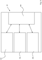
- FIG 1 a schematic representation of an embodiment of the monitoring system 1 according to the invention is shown.
- the monitoring system 1 comprises an extractor device 2, which is also referred to below as an extractor hood 2, a building services device 4 and a terminal 3.
- a server 5 of the communication network is also shown schematically, which represents a network server, for example.
- a sensor 20 is provided on the extractor hood 2 in the illustrated embodiment. However, more than one sensor 20 can also be provided on the extractor hood 2 .
- the sensor 20 can be provided in the interior of the extractor hood 2, in particular in the vicinity of the fan (not shown) of the extractor hood 2. Alternatively, however, the sensor 20 can also be provided on the outside of the extractor hood 2 , for example on the vapor screen of the extractor hood 2 . In this arrangement too, however, the sensor 20 is preferably provided in the vicinity of the intake opening of the extractor hood 2 .
- the extractor hood 2 also includes an interface 21.
- the interface 21 represents a communication interface and in particular a radio interface.
- the interface 21 preferably includes a transmitter unit and optionally a receiver unit which is connected to the transmitter unit or integrated in it.
- the interface 21 can therefore comprise a so-called transceiver unit.
- the interface 21 is shown separately from the sensor 20 in the illustrated embodiment. However, it is also within the scope of the invention for the interface 21 to be integrated in the sensor 20 .
- the building services device 4 can be, for example, a device for controlling windows, doors or blinds, or a security device such as an intruder monitoring device or a fire alarm.
- the building services device 4 has an interface 41 which represents a communication interface, in particular a radio interface, and can correspond to the interface 21 of the extractor hood 2 .
- the end device 3 can be a mobile phone, in particular a smartphone or a tablet PC, for example. At least part of a monitoring unit 30 is provided in the terminal 3 .
- This monitoring unit 30 preferably represents a program that is installed on the terminal and can be executed there.
- the monitoring unit 30 can thus represent a software program, in particular a so-called app, for example.
- the end device 3 includes an interface 31 which represents a communication interface, in particular a radio interface, and can correspond to the interface 21 of the extractor hood 2 .
- an output device 32 is provided on terminal 3, which in the embodiment shown represents a display unit in the form of a display.
- the interface 31 is preferably connected to the monitoring unit 30 for the transmission of data.
- the sensor 20 on the extractor hood 2 detects air parameters, such as the temperature, the humidity and/or parameters relating to the composition of the air, such as the content of solid or gaseous substances.
- Solid substances can be, for example, pollen or dust, while gaseous substances can be, for example, Co, CO2, SO2 or NOx.
- the sensor signals detected at the sensor 20 are preferably processed at the sensor 20 itself or in the interface 21 to form values that can also be referred to as sensor data.
- other sensor data such as information about the position of the sensor or environmental conditions of the sensor 20 , can also be transmitted to the interface 21 with the values determined from the sensor signals.
- the sensor data can then be transmitted wirelessly to the end device 3 via the interface 21 of the extractor hood 2 .
- the sensor data transmitted in this way are received at the interface 31 of the terminal device 3 .
- the sensor data are sent to the Monitoring unit 30 transmitted.
- the sensor data are preferably processed in the monitoring unit 30 .
- received sensor data can be compared with predefined threshold values or limit values.
- the sensor data can be brought into a format in which they can be output via the output device 32 and displayed in the case shown here.
- monitoring results can also be output. In particular, as in figure 2 shown, output when detecting the exceeding of one or more threshold values, that is to say that a change is required.
- information can also be transmitted from the building services device 4 to the terminal 3 via the interface 41 .
- This information can be, for example, the degree of opening of a window, the setting of an air conditioner and the like.
- the information received in this way at the interface 31 of the terminal 3 can be taken into account when processing the sensor data of the sensor 20 .
- the monitoring unit 30 can have several parts, which can, however, also be at least partially combined.
- the monitoring unit 30 has a processing unit 300, a control unit 301 for controlling at least one air influencing unit, a control unit 302 for activating warning mechanisms and an output unit 303 for outputting monitoring results.
- the processing unit 300 is preferably connected to the interface 31 of the mobile terminal device 3 .
- the processing unit 300 is provided on the terminal 3 .
- the processing unit 300 it is also possible for the processing unit 300 to be provided, for example, on the server 5 or another component of the monitoring system 1 and only to communicate with the other parts of the monitoring unit 30 on the mobile terminal device 3 .
- received sensor data in particular values determined from sensor signals, can be compared with one or several threshold or limit values. Depending on the result of the comparison, which can be referred to as the monitoring result, one of the other units of the monitoring unit 30 can be controlled.
- the control unit 301 can be activated to activate at least one air influencing unit or an air conveying device.
- a corresponding signal can be transmitted from the monitoring unit 30, in particular via the interface 31, to the corresponding building services device 4 and, for example, the heating for the room in which the air parameters were recorded can be turned down.
- the output unit 303 can be controlled to output monitoring results.
- an output for example a display on the output device 32, can be generated from which the user of the monitoring system 1 can see that the heating must be turned down or is currently being turned down.
- the processing unit 300 can control the control unit 302, for example, which is used to activate warning mechanisms.
- the communication unit (not shown) of the mobile terminal device 3 can be activated via the control unit 302 and an emergency call, for example to the treating doctor, can be made.
- the control units 301, 302 and the output unit 303 can be connected to one another in such a way that they can activate or control one another.
- the transmission of sensor data from the interface 21 of the extractor device 2 can also take place via the server 5 to the mobile terminal device 3 .
- the sensor data are preferably transmitted to the server 5 on which they are processed in a processing unit 300 of the monitoring unit 30 .
- the sensor data processed in this way or the monitoring results obtained from them can then be transmitted to the corresponding units 301 , 302 , 303 on the mobile terminal 3 .
- additional information such as information about the time of year or the outside temperature can also be taken into account in a simple manner when processing and selecting the unit 301, 302, 303 to be controlled.
- Processing unit 300 on the mobile terminal 3 itself such or other information, such as personal profiles of the user of the monitoring system 1 can be taken into account.
- the present invention is not limited to the illustrated embodiments and examples. Preferred embodiments of the invention can be summarized as follows. According to one embodiment, the integration of sensors in extractor hoods for the analysis of air parameters such as temperature, humidity, pollen and gaseous substances is made possible with the present invention. The parameters recorded are preferably evaluated using a corresponding app, for example on a smartphone or tablet PC.
- the air quality in the living space has a significant effect on the well-being and performance of people. Furthermore, an analysis of the air composition gives conclusions about harmful gases and substances that pose a burden or danger to allergy sufferers. In addition, room temperature and humidity also contribute to the energy requirement in private households and must therefore be set optimally from the point of view of energy efficiency.
- At least one sensor for detecting various air parameters such as temperature, humidity, pollen and gaseous substances (CO2, CO, SO2, NOx, etc.) is integrated into an extractor hood.
- the extractor hood including the sensor can represent part of a larger monitoring system, which can also be referred to as an overall system. Building technology (windows, doors, blinds) or security devices (alarms for burglary, fire) can also be integrated into the monitoring system.
- the sensor on the extractor hood records the air values during and without operation of the extractor hood. In the first case, more comprehensive results can be inferred, since air masses are sucked in from the entire living space.
- the sensor has a radio interface or is connected to one and forwards the recorded values to a special app/software on a smartphone. The app/software evaluates the data and gives the user feedback on the composition of the air and tips for possible improvements.
- the present invention represents a space-saving solution, since the integration of the sensor in the extractor housing means that no separate space is required in the living space.
- the analysis of the air sucked in by the extractor hood provides qualitatively better results than the analysis of still air.
- mold can be avoided because an optimal air composition can be set.
- the safety in the living area is increased. In the event of smoke or fire gas detection, an emergency call can be made automatically via the app.
- the quality of life is increased by better air in the living space.
- the present invention can also serve as an aid for allergy sufferers, such as those allergic to grass pollen, or asthmatics. Energy savings can be achieved through the optimum living room temperature.
- additional advantages can be derived from the integration into other systems in the household such as security (movement detectors, fire alarms, etc.).
Landscapes
- Engineering & Computer Science (AREA)
- Chemical & Material Sciences (AREA)
- Combustion & Propulsion (AREA)
- Mechanical Engineering (AREA)
- General Engineering & Computer Science (AREA)
- Human Computer Interaction (AREA)
- Signal Processing (AREA)
- Physics & Mathematics (AREA)
- Health & Medical Sciences (AREA)
- Life Sciences & Earth Sciences (AREA)
- Mathematical Physics (AREA)
- Fuzzy Systems (AREA)
- Analytical Chemistry (AREA)
- General Physics & Mathematics (AREA)
- Immunology (AREA)
- Pathology (AREA)
- General Health & Medical Sciences (AREA)
- Biochemistry (AREA)
- Molecular Biology (AREA)
- Biomedical Technology (AREA)
- Air Conditioning Control Device (AREA)
- Ventilation (AREA)
- Telephonic Communication Services (AREA)
Applications Claiming Priority (1)
| Application Number | Priority Date | Filing Date | Title |
|---|---|---|---|
| DE102012220598.5A DE102012220598A1 (de) | 2012-11-13 | 2012-11-13 | Überwachungssystem und Verfahren zur Überwachung und Einstellung von Luftparametern in einem Raum, Dunstabzugsvorrichtung zur Verwendung in einem Überwachungssystem |
Publications (2)
| Publication Number | Publication Date |
|---|---|
| EP2735809A1 EP2735809A1 (de) | 2014-05-28 |
| EP2735809B1 true EP2735809B1 (de) | 2022-05-18 |
Family
ID=49484185
Family Applications (1)
| Application Number | Title | Priority Date | Filing Date |
|---|---|---|---|
| EP13190109.2A Active EP2735809B1 (de) | 2012-11-13 | 2013-10-24 | Überwachungssystem und Verfahren zur Überwachung und Einstellung von Luftparametern in einem Raum, Dunstabzugsvorrichtung zur Verwendung in einem Überwachungssystem |
Country Status (5)
| Country | Link |
|---|---|
| US (1) | US10473565B2 (pl) |
| EP (1) | EP2735809B1 (pl) |
| DE (1) | DE102012220598A1 (pl) |
| ES (1) | ES2922203T3 (pl) |
| PL (1) | PL2735809T3 (pl) |
Families Citing this family (34)
| Publication number | Priority date | Publication date | Assignee | Title |
|---|---|---|---|---|
| US11175268B2 (en) | 2014-06-09 | 2021-11-16 | Biometry Inc. | Mini point of care gas chromatographic test strip and method to measure analytes |
| JP6903574B2 (ja) | 2014-06-09 | 2021-07-14 | バイオメトリー・インコーポレイテッドBiometry Inc. | 検体を測定するための低コストテストストリップ及び方法 |
| DE102014217934A1 (de) | 2014-09-08 | 2015-08-27 | Robert Bosch Gmbh | Verfahren und Messeinrichtung zum Belüften eines Innenraums |
| US20160146769A1 (en) * | 2014-11-21 | 2016-05-26 | Xiaomi Inc. | Methods and devices for acquiring air quality |
| CN104456677B (zh) * | 2014-11-26 | 2016-09-07 | 浙江苏泊尔家电制造有限公司 | 带呼叫按键的吸油烟机控制系统及控制方法 |
| DE102015210119A1 (de) * | 2015-06-02 | 2016-12-08 | BSH Hausgeräte GmbH | Dunstabzugshaube und Verfahren zur Ausgabe der Lüftgüte |
| CN105160846A (zh) * | 2015-08-26 | 2015-12-16 | 佛山市惠更好电子有限公司 | 一种油烟机万能遥控开关 |
| CN105650818A (zh) * | 2016-01-29 | 2016-06-08 | 沈阳英林特电器有限公司 | 一种厨房环境的净化方法、相关装置和系统 |
| CN105546606A (zh) * | 2016-01-29 | 2016-05-04 | 沈阳英林特电器有限公司 | 一种厨房空气的净化方法、相关装置和系统 |
| DE102016105340A1 (de) | 2016-03-22 | 2017-09-28 | Webasto SE | Verfahren und System zur Überwachung einer Basiseinrichtung durch ein mobiles Endgerät |
| GB2550600A (en) * | 2016-05-24 | 2017-11-29 | Bofa International Ltd | Fume extraction systems |
| CA3031247A1 (en) | 2016-07-19 | 2018-01-25 | Biometry Inc. | Methods of and systems for measuring analytes using batch calibratable test strips |
| CN106255046A (zh) * | 2016-09-16 | 2016-12-21 | 上海丛荣信息科技有限公司 | 一种低功耗模块化智能互联系统及方法 |
| CN108362826A (zh) | 2017-01-26 | 2018-08-03 | Bsh家用电器有限公司 | 食物处理时的空气质量 |
| CN108572555A (zh) * | 2017-03-08 | 2018-09-25 | 博西华电器(江苏)有限公司 | 油烟机和基于油烟机的家庭互联控制方法 |
| US10458669B2 (en) | 2017-03-29 | 2019-10-29 | Johnson Controls Technology Company | Thermostat with interactive installation features |
| CN106768086A (zh) * | 2017-04-06 | 2017-05-31 | 四川理工学院 | 一种室内空气检测系统 |
| US10837665B2 (en) | 2017-04-14 | 2020-11-17 | Johnson Controls Technology Company | Multi-function thermostat with intelligent ventilator control for frost/mold protection and air quality control |
| WO2018191699A1 (en) | 2017-04-14 | 2018-10-18 | Johnson Controls Technology Company | Multi-function thermostat with intelligent supply fan control for maximizing air quality and optimizing energy usage |
| WO2018191510A1 (en) | 2017-04-14 | 2018-10-18 | Johnson Controls Technology Company | Multi-function thermostat with air quality display |
| WO2018191688A2 (en) | 2017-04-14 | 2018-10-18 | Johnson Controls Techology Company | Thermostat with exhaust fan control for air quality and humidity control |
| US10866003B2 (en) | 2017-04-14 | 2020-12-15 | Johnson Controls Technology Company | Thermostat with preemptive heating, cooling, and ventilation in response to elevated occupancy detection via proxy |
| US10731885B2 (en) | 2017-04-14 | 2020-08-04 | Johnson Controls Technology Company | Thermostat with occupancy detection via proxy measurements of a proxy sensor |
| DE102017003359A1 (de) * | 2017-05-11 | 2018-11-15 | Jürgen Geck | Verfahren zum Betreiben eines Datenverarbeitungssystems |
| US10452046B2 (en) | 2017-06-29 | 2019-10-22 | Midea Group Co., Ltd. | Cooking appliance control of residential heating, ventilation and/or air conditioning (HVAC) system |
| US11131474B2 (en) | 2018-03-09 | 2021-09-28 | Johnson Controls Tyco IP Holdings LLP | Thermostat with user interface features |
| DE102019116756A1 (de) * | 2019-06-20 | 2020-12-24 | Wagener Gastronomieproduktion Gmbh | Ablufthaube und Ablufthaubensystem |
| CN110454836A (zh) * | 2019-08-28 | 2019-11-15 | 河南博联慧绿环保科技有限公司 | 一种餐厨油烟五段式综合治理系统 |
| DE102019219517A1 (de) * | 2019-12-13 | 2021-06-17 | Robert Bosch Gmbh | Verfahren und Vorrichtung zur Anpassung einer Umgebungsbedingung für eine Analyse einer Atemluft, insbesondere über eine Ansteuerung eines Smart-Home-Systems |
| DE102021213631A1 (de) | 2021-12-01 | 2023-06-01 | Robert Bosch Gesellschaft mit beschränkter Haftung | Gefahrenerfassungsvorrichtung |
| DE102022116083A1 (de) | 2022-06-28 | 2023-12-28 | Berbel Ablufttechnik Gmbh | Verfahren zur automatisierten Steuerung einer Dunstabzugshaube und Dunstabzugshaube eingerichtet zur Durchführung des Verfahrens |
| US12313275B2 (en) * | 2023-03-28 | 2025-05-27 | Honeywell International Inc. | System and method for personalizing a user interface of a fume hood monitor based on the identify of a detected user |
| US12361812B2 (en) * | 2023-03-28 | 2025-07-15 | Honeywell International Inc. | Methods and systems for remotely interacting with a fume hood using a mobile device |
| EP4628799A1 (en) * | 2024-04-04 | 2025-10-08 | SMEG S.p.A. | Filtration unit, filter hood and monitoring and control method of the filter hood |
Citations (3)
| Publication number | Priority date | Publication date | Assignee | Title |
|---|---|---|---|---|
| KR20100093920A (ko) * | 2009-02-17 | 2010-08-26 | (주)서브제로코리아 | 레인지 후드 시스템 및 그 제어방법 |
| EP2022244B1 (en) * | 2006-05-30 | 2011-05-18 | Indesit Company S.p.A. | Electric appliance |
| CA2775647A1 (en) * | 2011-05-11 | 2012-11-11 | Lennox Industries Inc. | System and method for automatically programming hvac system temperature adjustment times |
Family Cites Families (10)
| Publication number | Priority date | Publication date | Assignee | Title |
|---|---|---|---|---|
| JP3522686B2 (ja) * | 2000-12-13 | 2004-04-26 | 松下電器産業株式会社 | 移動体端末並びに自動遠隔制御システムおよび自動遠隔制御方法 |
| US6920874B1 (en) * | 2004-03-01 | 2005-07-26 | Robert Paul Siegel | Intelligent ventilating safety range hood |
| US20050224069A1 (en) * | 2004-03-29 | 2005-10-13 | Patil Mahendra M | System and method for managing air from a cooktop |
| US7713173B2 (en) * | 2005-11-28 | 2010-05-11 | Samsung Electronics Co., Ltd | Exercise management function providing system and method |
| US8498749B2 (en) * | 2009-08-21 | 2013-07-30 | Allure Energy, Inc. | Method for zone based energy management system with scalable map interface |
| MX2012003742A (es) * | 2009-09-28 | 2012-10-10 | Illuminare Holdings Ltd | Dispositivo de verificacion intravaginal y red. |
| US20120064951A1 (en) * | 2010-09-13 | 2012-03-15 | Sony Ericsson Mobile Communications Ab | Hands-Free Control of Mobile Communication Device Based on Head Movement |
| US9533654B2 (en) * | 2010-12-17 | 2017-01-03 | GM Global Technology Operations LLC | Vehicle data services enabled by low power FM transmission |
| US9053626B2 (en) * | 2011-05-02 | 2015-06-09 | Daydream Believers, Llc | Programmable carbon monoxide safety device |
| US8779926B2 (en) * | 2011-12-29 | 2014-07-15 | Schechter Tech, Llc | Presenting information regarding conditions of an environment with a visual representation of the environment |
-
2012
- 2012-11-13 DE DE102012220598.5A patent/DE102012220598A1/de not_active Withdrawn
-
2013
- 2013-10-24 PL PL13190109.2T patent/PL2735809T3/pl unknown
- 2013-10-24 ES ES13190109T patent/ES2922203T3/es active Active
- 2013-10-24 EP EP13190109.2A patent/EP2735809B1/de active Active
- 2013-10-31 US US14/068,037 patent/US10473565B2/en active Active
Patent Citations (3)
| Publication number | Priority date | Publication date | Assignee | Title |
|---|---|---|---|---|
| EP2022244B1 (en) * | 2006-05-30 | 2011-05-18 | Indesit Company S.p.A. | Electric appliance |
| KR20100093920A (ko) * | 2009-02-17 | 2010-08-26 | (주)서브제로코리아 | 레인지 후드 시스템 및 그 제어방법 |
| CA2775647A1 (en) * | 2011-05-11 | 2012-11-11 | Lennox Industries Inc. | System and method for automatically programming hvac system temperature adjustment times |
Also Published As
| Publication number | Publication date |
|---|---|
| PL2735809T3 (pl) | 2022-08-29 |
| US10473565B2 (en) | 2019-11-12 |
| EP2735809A1 (de) | 2014-05-28 |
| DE102012220598A1 (de) | 2014-05-28 |
| ES2922203T3 (es) | 2022-09-09 |
| US20140130574A1 (en) | 2014-05-15 |
Similar Documents
| Publication | Publication Date | Title |
|---|---|---|
| EP2735809B1 (de) | Überwachungssystem und Verfahren zur Überwachung und Einstellung von Luftparametern in einem Raum, Dunstabzugsvorrichtung zur Verwendung in einem Überwachungssystem | |
| DE102014007177A1 (de) | System zum Steuern wenigstens eines Hausgerätes | |
| WO2014019862A1 (de) | Dunstabzugsvorrichtung und verfahren zum ansteuerung eines lüftermotors eines lüfters und zur luftreinigungswirkungsermittlung | |
| EP4200823A1 (de) | Verfahren zum überwachen eines kochvorgangs und steuervorrichtung | |
| EP1341158A2 (de) | Sprachgesteuertes elektrisches Gerät, insbesondere Dunstabzugshaube | |
| EP1452804A1 (de) | Einrichtung zum Absaugen von Abluft eines Elektrowärmegeräts und Verfahren zum Betrieb derselben | |
| DE102010006455B4 (de) | Verfahren, Steuereinrichtung und -system zur Be-und Entlüftung eines Gesamtraums mit mehreren Teilräumen, insbesondere eines eine Wohneinheit bildenden Gesamtraums | |
| DE102020210477B4 (de) | Verfahren zum Betrieb einer Dunstabzugsvorrichtung, Steuervorrichtung sowie Dunstabzugsvorrichtung | |
| EP4379494A1 (de) | Heizungsthermostat | |
| EP0670026A1 (de) | Zuluftgerät | |
| DE202022102096U1 (de) | System zur Echtzeit-Überwachung der Luftverschmutzung in geschlossenen Räumen mit Hilfe von Sensoren aus dem Internet der Dinge | |
| EP3108903B1 (de) | Desinfektionseinrichtung zum desinfizieren von räumen sowie verfahren zum desinfizieren von räumen | |
| EP3143342B1 (de) | Steuereinrichtung für eine raumlüftungseinrichtung und verfahren zur belüftung eines raums | |
| EP1382914A2 (de) | Luftabzugsvorrichtung und Luftabzugsverfahren | |
| EP4299990A1 (de) | Verfahren zur automatisierten steuerung einer dunstabzugshaube und dunstabzugshaube eingerichtet zur durchführung des verfahrens | |
| EP3646126B1 (de) | Mobile einheit, mobiles endgerät und dazugehöriges verfahren | |
| WO2023139120A1 (de) | Wärmepumpenvorrichtung, wärmepumpe mit einer solchen wärmepumpenvorrichtung und verfahren zum betrieb einer solchen wärmepumpenvorrichtung | |
| EP0670027A1 (de) | Abluftgerät | |
| WO2004092656A1 (de) | Luftabzugseinrichtung und luftabzugsverfahren | |
| DE102022131181A1 (de) | System zur Lüftung eines Raumes | |
| DE102023212876A1 (de) | Verfahren zur Überwachung eines Bereichs | |
| DE102018202886B4 (de) | Dockingstation und Verfahren und Gebäude oder Verkehrsmittel und Datenträger zur Bestimmung von zumindest einem Umgebungsparameter | |
| EP3799363A2 (de) | Verfahren zum betreiben von sensoren | |
| DE102017223172A1 (de) | Steuerung einer Luftreinigungsvorrichtung | |
| EP2028576A1 (de) | Gebäudemanagementsystem bzw. zugehörige Aktoren |
Legal Events
| Date | Code | Title | Description |
|---|---|---|---|
| PUAI | Public reference made under article 153(3) epc to a published international application that has entered the european phase |
Free format text: ORIGINAL CODE: 0009012 |
|
| 17P | Request for examination filed |
Effective date: 20131024 |
|
| AK | Designated contracting states |
Kind code of ref document: A1 Designated state(s): AL AT BE BG CH CY CZ DE DK EE ES FI FR GB GR HR HU IE IS IT LI LT LU LV MC MK MT NL NO PL PT RO RS SE SI SK SM TR |
|
| AX | Request for extension of the european patent |
Extension state: BA ME |
|
| R17P | Request for examination filed (corrected) |
Effective date: 20141128 |
|
| RBV | Designated contracting states (corrected) |
Designated state(s): AL AT BE BG CH CY CZ DE DK EE ES FI FR GB GR HR HU IE IS IT LI LT LU LV MC MK MT NL NO PL PT RO RS SE SI SK SM TR |
|
| RAP1 | Party data changed (applicant data changed or rights of an application transferred) |
Owner name: BSH HAUSGERAETE GMBH |
|
| STAA | Information on the status of an ep patent application or granted ep patent |
Free format text: STATUS: EXAMINATION IS IN PROGRESS |
|
| 17Q | First examination report despatched |
Effective date: 20180927 |
|
| RIC1 | Information provided on ipc code assigned before grant |
Ipc: F24F 7/00 20210101ALI20211109BHEP Ipc: F24F 11/30 20180101ALI20211109BHEP Ipc: F24F 110/00 20180101ALI20211109BHEP Ipc: F24C 15/20 20060101ALI20211109BHEP Ipc: F24F 11/00 20180101AFI20211109BHEP |
|
| GRAP | Despatch of communication of intention to grant a patent |
Free format text: ORIGINAL CODE: EPIDOSNIGR1 |
|
| STAA | Information on the status of an ep patent application or granted ep patent |
Free format text: STATUS: GRANT OF PATENT IS INTENDED |
|
| INTG | Intention to grant announced |
Effective date: 20211221 |
|
| GRAS | Grant fee paid |
Free format text: ORIGINAL CODE: EPIDOSNIGR3 |
|
| GRAA | (expected) grant |
Free format text: ORIGINAL CODE: 0009210 |
|
| STAA | Information on the status of an ep patent application or granted ep patent |
Free format text: STATUS: THE PATENT HAS BEEN GRANTED |
|
| AK | Designated contracting states |
Kind code of ref document: B1 Designated state(s): AL AT BE BG CH CY CZ DE DK EE ES FI FR GB GR HR HU IE IS IT LI LT LU LV MC MK MT NL NO PL PT RO RS SE SI SK SM TR |
|
| REG | Reference to a national code |
Ref country code: GB Ref legal event code: FG4D Free format text: NOT ENGLISH |
|
| REG | Reference to a national code |
Ref country code: CH Ref legal event code: EP |
|
| REG | Reference to a national code |
Ref country code: IE Ref legal event code: FG4D Free format text: LANGUAGE OF EP DOCUMENT: GERMAN |
|
| REG | Reference to a national code |
Ref country code: DE Ref legal event code: R096 Ref document number: 502013016145 Country of ref document: DE |
|
| REG | Reference to a national code |
Ref country code: AT Ref legal event code: REF Ref document number: 1493360 Country of ref document: AT Kind code of ref document: T Effective date: 20220615 |
|
| REG | Reference to a national code |
Ref country code: ES Ref legal event code: FG2A Ref document number: 2922203 Country of ref document: ES Kind code of ref document: T3 Effective date: 20220909 |
|
| REG | Reference to a national code |
Ref country code: LT Ref legal event code: MG9D |
|
| REG | Reference to a national code |
Ref country code: NL Ref legal event code: MP Effective date: 20220518 |
|
| PG25 | Lapsed in a contracting state [announced via postgrant information from national office to epo] |
Ref country code: SE Free format text: LAPSE BECAUSE OF FAILURE TO SUBMIT A TRANSLATION OF THE DESCRIPTION OR TO PAY THE FEE WITHIN THE PRESCRIBED TIME-LIMIT Effective date: 20220518 Ref country code: PT Free format text: LAPSE BECAUSE OF FAILURE TO SUBMIT A TRANSLATION OF THE DESCRIPTION OR TO PAY THE FEE WITHIN THE PRESCRIBED TIME-LIMIT Effective date: 20220919 Ref country code: NO Free format text: LAPSE BECAUSE OF FAILURE TO SUBMIT A TRANSLATION OF THE DESCRIPTION OR TO PAY THE FEE WITHIN THE PRESCRIBED TIME-LIMIT Effective date: 20220818 Ref country code: NL Free format text: LAPSE BECAUSE OF FAILURE TO SUBMIT A TRANSLATION OF THE DESCRIPTION OR TO PAY THE FEE WITHIN THE PRESCRIBED TIME-LIMIT Effective date: 20220518 Ref country code: LT Free format text: LAPSE BECAUSE OF FAILURE TO SUBMIT A TRANSLATION OF THE DESCRIPTION OR TO PAY THE FEE WITHIN THE PRESCRIBED TIME-LIMIT Effective date: 20220518 Ref country code: HR Free format text: LAPSE BECAUSE OF FAILURE TO SUBMIT A TRANSLATION OF THE DESCRIPTION OR TO PAY THE FEE WITHIN THE PRESCRIBED TIME-LIMIT Effective date: 20220518 Ref country code: GR Free format text: LAPSE BECAUSE OF FAILURE TO SUBMIT A TRANSLATION OF THE DESCRIPTION OR TO PAY THE FEE WITHIN THE PRESCRIBED TIME-LIMIT Effective date: 20220819 Ref country code: FI Free format text: LAPSE BECAUSE OF FAILURE TO SUBMIT A TRANSLATION OF THE DESCRIPTION OR TO PAY THE FEE WITHIN THE PRESCRIBED TIME-LIMIT Effective date: 20220518 Ref country code: BG Free format text: LAPSE BECAUSE OF FAILURE TO SUBMIT A TRANSLATION OF THE DESCRIPTION OR TO PAY THE FEE WITHIN THE PRESCRIBED TIME-LIMIT Effective date: 20220818 |
|
| PG25 | Lapsed in a contracting state [announced via postgrant information from national office to epo] |
Ref country code: RS Free format text: LAPSE BECAUSE OF FAILURE TO SUBMIT A TRANSLATION OF THE DESCRIPTION OR TO PAY THE FEE WITHIN THE PRESCRIBED TIME-LIMIT Effective date: 20220518 Ref country code: LV Free format text: LAPSE BECAUSE OF FAILURE TO SUBMIT A TRANSLATION OF THE DESCRIPTION OR TO PAY THE FEE WITHIN THE PRESCRIBED TIME-LIMIT Effective date: 20220518 Ref country code: IS Free format text: LAPSE BECAUSE OF FAILURE TO SUBMIT A TRANSLATION OF THE DESCRIPTION OR TO PAY THE FEE WITHIN THE PRESCRIBED TIME-LIMIT Effective date: 20220918 |
|
| PG25 | Lapsed in a contracting state [announced via postgrant information from national office to epo] |
Ref country code: SM Free format text: LAPSE BECAUSE OF FAILURE TO SUBMIT A TRANSLATION OF THE DESCRIPTION OR TO PAY THE FEE WITHIN THE PRESCRIBED TIME-LIMIT Effective date: 20220518 Ref country code: SK Free format text: LAPSE BECAUSE OF FAILURE TO SUBMIT A TRANSLATION OF THE DESCRIPTION OR TO PAY THE FEE WITHIN THE PRESCRIBED TIME-LIMIT Effective date: 20220518 Ref country code: RO Free format text: LAPSE BECAUSE OF FAILURE TO SUBMIT A TRANSLATION OF THE DESCRIPTION OR TO PAY THE FEE WITHIN THE PRESCRIBED TIME-LIMIT Effective date: 20220518 Ref country code: EE Free format text: LAPSE BECAUSE OF FAILURE TO SUBMIT A TRANSLATION OF THE DESCRIPTION OR TO PAY THE FEE WITHIN THE PRESCRIBED TIME-LIMIT Effective date: 20220518 Ref country code: DK Free format text: LAPSE BECAUSE OF FAILURE TO SUBMIT A TRANSLATION OF THE DESCRIPTION OR TO PAY THE FEE WITHIN THE PRESCRIBED TIME-LIMIT Effective date: 20220518 Ref country code: CZ Free format text: LAPSE BECAUSE OF FAILURE TO SUBMIT A TRANSLATION OF THE DESCRIPTION OR TO PAY THE FEE WITHIN THE PRESCRIBED TIME-LIMIT Effective date: 20220518 |
|
| REG | Reference to a national code |
Ref country code: DE Ref legal event code: R097 Ref document number: 502013016145 Country of ref document: DE |
|
| REG | Reference to a national code |
Ref country code: DE Ref legal event code: R084 Ref document number: 502013016145 Country of ref document: DE |
|
| PLBE | No opposition filed within time limit |
Free format text: ORIGINAL CODE: 0009261 |
|
| STAA | Information on the status of an ep patent application or granted ep patent |
Free format text: STATUS: NO OPPOSITION FILED WITHIN TIME LIMIT |
|
| PG25 | Lapsed in a contracting state [announced via postgrant information from national office to epo] |
Ref country code: AL Free format text: LAPSE BECAUSE OF FAILURE TO SUBMIT A TRANSLATION OF THE DESCRIPTION OR TO PAY THE FEE WITHIN THE PRESCRIBED TIME-LIMIT Effective date: 20220518 |
|
| 26N | No opposition filed |
Effective date: 20230221 |
|
| PG25 | Lapsed in a contracting state [announced via postgrant information from national office to epo] |
Ref country code: SI Free format text: LAPSE BECAUSE OF FAILURE TO SUBMIT A TRANSLATION OF THE DESCRIPTION OR TO PAY THE FEE WITHIN THE PRESCRIBED TIME-LIMIT Effective date: 20220518 Ref country code: MC Free format text: LAPSE BECAUSE OF FAILURE TO SUBMIT A TRANSLATION OF THE DESCRIPTION OR TO PAY THE FEE WITHIN THE PRESCRIBED TIME-LIMIT Effective date: 20220518 |
|
| REG | Reference to a national code |
Ref country code: CH Ref legal event code: PL |
|
| P01 | Opt-out of the competence of the unified patent court (upc) registered |
Effective date: 20230510 |
|
| PG25 | Lapsed in a contracting state [announced via postgrant information from national office to epo] |
Ref country code: LU Free format text: LAPSE BECAUSE OF NON-PAYMENT OF DUE FEES Effective date: 20221024 |
|
| PG25 | Lapsed in a contracting state [announced via postgrant information from national office to epo] |
Ref country code: LI Free format text: LAPSE BECAUSE OF NON-PAYMENT OF DUE FEES Effective date: 20221031 Ref country code: FR Free format text: LAPSE BECAUSE OF NON-PAYMENT OF DUE FEES Effective date: 20221031 Ref country code: CH Free format text: LAPSE BECAUSE OF NON-PAYMENT OF DUE FEES Effective date: 20221031 |
|
| PG25 | Lapsed in a contracting state [announced via postgrant information from national office to epo] |
Ref country code: IE Free format text: LAPSE BECAUSE OF NON-PAYMENT OF DUE FEES Effective date: 20221024 |
|
| REG | Reference to a national code |
Ref country code: AT Ref legal event code: MM01 Ref document number: 1493360 Country of ref document: AT Kind code of ref document: T Effective date: 20221024 |
|
| PG25 | Lapsed in a contracting state [announced via postgrant information from national office to epo] |
Ref country code: AT Free format text: LAPSE BECAUSE OF NON-PAYMENT OF DUE FEES Effective date: 20221024 |
|
| PG25 | Lapsed in a contracting state [announced via postgrant information from national office to epo] |
Ref country code: HU Free format text: LAPSE BECAUSE OF FAILURE TO SUBMIT A TRANSLATION OF THE DESCRIPTION OR TO PAY THE FEE WITHIN THE PRESCRIBED TIME-LIMIT; INVALID AB INITIO Effective date: 20131024 |
|
| PG25 | Lapsed in a contracting state [announced via postgrant information from national office to epo] |
Ref country code: CY Free format text: LAPSE BECAUSE OF FAILURE TO SUBMIT A TRANSLATION OF THE DESCRIPTION OR TO PAY THE FEE WITHIN THE PRESCRIBED TIME-LIMIT Effective date: 20220511 |
|
| PG25 | Lapsed in a contracting state [announced via postgrant information from national office to epo] |
Ref country code: MK Free format text: LAPSE BECAUSE OF FAILURE TO SUBMIT A TRANSLATION OF THE DESCRIPTION OR TO PAY THE FEE WITHIN THE PRESCRIBED TIME-LIMIT Effective date: 20220511 |
|
| REG | Reference to a national code |
Ref country code: ES Ref legal event code: GC2A Effective date: 20240906 |
|
| PG25 | Lapsed in a contracting state [announced via postgrant information from national office to epo] |
Ref country code: MT Free format text: LAPSE BECAUSE OF FAILURE TO SUBMIT A TRANSLATION OF THE DESCRIPTION OR TO PAY THE FEE WITHIN THE PRESCRIBED TIME-LIMIT Effective date: 20220511 |
|
| PG25 | Lapsed in a contracting state [announced via postgrant information from national office to epo] |
Ref country code: BG Free format text: LAPSE BECAUSE OF FAILURE TO SUBMIT A TRANSLATION OF THE DESCRIPTION OR TO PAY THE FEE WITHIN THE PRESCRIBED TIME-LIMIT Effective date: 20220518 |
|
| PG25 | Lapsed in a contracting state [announced via postgrant information from national office to epo] |
Ref country code: BG Free format text: LAPSE BECAUSE OF FAILURE TO SUBMIT A TRANSLATION OF THE DESCRIPTION OR TO PAY THE FEE WITHIN THE PRESCRIBED TIME-LIMIT Effective date: 20220518 |
|
| PGFP | Annual fee paid to national office [announced via postgrant information from national office to epo] |
Ref country code: DE Payment date: 20251031 Year of fee payment: 13 |
|
| PGFP | Annual fee paid to national office [announced via postgrant information from national office to epo] |
Ref country code: GB Payment date: 20251024 Year of fee payment: 13 |
|
| PGFP | Annual fee paid to national office [announced via postgrant information from national office to epo] |
Ref country code: IT Payment date: 20251031 Year of fee payment: 13 |
|
| PGFP | Annual fee paid to national office [announced via postgrant information from national office to epo] |
Ref country code: BE Payment date: 20251022 Year of fee payment: 13 Ref country code: TR Payment date: 20251022 Year of fee payment: 13 |
|
| PGFP | Annual fee paid to national office [announced via postgrant information from national office to epo] |
Ref country code: PL Payment date: 20251010 Year of fee payment: 13 |
|
| PGFP | Annual fee paid to national office [announced via postgrant information from national office to epo] |
Ref country code: ES Payment date: 20251114 Year of fee payment: 13 |