EP2735680A2 - Kältegerät mit Türscharnieranordnung - Google Patents
Kältegerät mit Türscharnieranordnung Download PDFInfo
- Publication number
- EP2735680A2 EP2735680A2 EP13191404.6A EP13191404A EP2735680A2 EP 2735680 A2 EP2735680 A2 EP 2735680A2 EP 13191404 A EP13191404 A EP 13191404A EP 2735680 A2 EP2735680 A2 EP 2735680A2
- Authority
- EP
- European Patent Office
- Prior art keywords
- lift member
- adjusting part
- door
- refrigeration appliance
- hinge
- Prior art date
- Legal status (The legal status is an assumption and is not a legal conclusion. Google has not performed a legal analysis and makes no representation as to the accuracy of the status listed.)
- Withdrawn
Links
- 238000005057 refrigeration Methods 0.000 title claims abstract description 35
- 230000002093 peripheral effect Effects 0.000 claims description 12
- 230000000284 resting effect Effects 0.000 description 3
- 238000000034 method Methods 0.000 description 2
- 230000008569 process Effects 0.000 description 2
- 230000004323 axial length Effects 0.000 description 1
- 230000009286 beneficial effect Effects 0.000 description 1
- 230000008859 change Effects 0.000 description 1
- 230000001419 dependent effect Effects 0.000 description 1
- 230000000694 effects Effects 0.000 description 1
- 230000007246 mechanism Effects 0.000 description 1
- 239000007787 solid Substances 0.000 description 1
- 230000007704 transition Effects 0.000 description 1
Images



Classifications
-
- E—FIXED CONSTRUCTIONS
- E05—LOCKS; KEYS; WINDOW OR DOOR FITTINGS; SAFES
- E05D—HINGES OR SUSPENSION DEVICES FOR DOORS, WINDOWS OR WINGS
- E05D7/00—Hinges or pivots of special construction
- E05D7/0009—Adjustable hinges
- E05D7/0018—Adjustable hinges at the hinge axis
- E05D7/0027—Adjustable hinges at the hinge axis in an axial direction
-
- E—FIXED CONSTRUCTIONS
- E05—LOCKS; KEYS; WINDOW OR DOOR FITTINGS; SAFES
- E05D—HINGES OR SUSPENSION DEVICES FOR DOORS, WINDOWS OR WINGS
- E05D7/00—Hinges or pivots of special construction
- E05D7/08—Hinges or pivots of special construction for use in suspensions comprising two spigots placed at opposite edges of the wing, especially at the top and the bottom, e.g. trunnions
- E05D7/081—Hinges or pivots of special construction for use in suspensions comprising two spigots placed at opposite edges of the wing, especially at the top and the bottom, e.g. trunnions the pivot axis of the wing being situated near one edge of the wing, especially at the top and bottom, e.g. trunnions
-
- E—FIXED CONSTRUCTIONS
- E05—LOCKS; KEYS; WINDOW OR DOOR FITTINGS; SAFES
- E05F—DEVICES FOR MOVING WINGS INTO OPEN OR CLOSED POSITION; CHECKS FOR WINGS; WING FITTINGS NOT OTHERWISE PROVIDED FOR, CONCERNED WITH THE FUNCTIONING OF THE WING
- E05F1/00—Closers or openers for wings, not otherwise provided for in this subclass
- E05F1/02—Closers or openers for wings, not otherwise provided for in this subclass gravity-actuated, e.g. by use of counterweights
- E05F1/04—Closers or openers for wings, not otherwise provided for in this subclass gravity-actuated, e.g. by use of counterweights for wings which lift during movement, operated by their own weight
- E05F1/06—Mechanisms in the shape of hinges or pivots, operated by the weight of the wing
- E05F1/061—Mechanisms in the shape of hinges or pivots, operated by the weight of the wing with cams or helical tracks
- E05F1/063—Mechanisms in the shape of hinges or pivots, operated by the weight of the wing with cams or helical tracks with complementary, substantially identical and slidingly cooperating cam surfaces
-
- F—MECHANICAL ENGINEERING; LIGHTING; HEATING; WEAPONS; BLASTING
- F25—REFRIGERATION OR COOLING; COMBINED HEATING AND REFRIGERATION SYSTEMS; HEAT PUMP SYSTEMS; MANUFACTURE OR STORAGE OF ICE; LIQUEFACTION SOLIDIFICATION OF GASES
- F25D—REFRIGERATORS; COLD ROOMS; ICE-BOXES; COOLING OR FREEZING APPARATUS NOT OTHERWISE PROVIDED FOR
- F25D23/00—General constructional features
- F25D23/02—Doors; Covers
- F25D23/028—Details
-
- E—FIXED CONSTRUCTIONS
- E05—LOCKS; KEYS; WINDOW OR DOOR FITTINGS; SAFES
- E05Y—INDEXING SCHEME ASSOCIATED WITH SUBCLASSES E05D AND E05F, RELATING TO CONSTRUCTION ELEMENTS, ELECTRIC CONTROL, POWER SUPPLY, POWER SIGNAL OR TRANSMISSION, USER INTERFACES, MOUNTING OR COUPLING, DETAILS, ACCESSORIES, AUXILIARY OPERATIONS NOT OTHERWISE PROVIDED FOR, APPLICATION THEREOF
- E05Y2900/00—Application of doors, windows, wings or fittings thereof
- E05Y2900/30—Application of doors, windows, wings or fittings thereof for domestic appliances
- E05Y2900/31—Application of doors, windows, wings or fittings thereof for domestic appliances for refrigerators
-
- F—MECHANICAL ENGINEERING; LIGHTING; HEATING; WEAPONS; BLASTING
- F25—REFRIGERATION OR COOLING; COMBINED HEATING AND REFRIGERATION SYSTEMS; HEAT PUMP SYSTEMS; MANUFACTURE OR STORAGE OF ICE; LIQUEFACTION SOLIDIFICATION OF GASES
- F25D—REFRIGERATORS; COLD ROOMS; ICE-BOXES; COOLING OR FREEZING APPARATUS NOT OTHERWISE PROVIDED FOR
- F25D2323/00—General constructional features not provided for in other groups of this subclass
- F25D2323/02—Details of doors or covers not otherwise covered
- F25D2323/024—Door hinges
Definitions
- the present invention relates to a refrigeration appliance, and in particular, to a refrigeration appliance having a door hinge assembly, such as a refrigerator, a wine cooler or a freezer.
- CN102365515A discloses an adjustable hinge assembly for a pivot door, including a pivot shaft fixed to a hinge plate, an adjusting part sleeved on the pivot shaft and a locking member for maintaining the position of the adjusting part along the pivot shaft, where the pivot shaft has a thread portion and defines a rotation axis of the door, and the adjusting part has an inner thread which is rotatable along the thread portion of the pivot shaft to adjust the height of the door.
- the locking member extends through one of multiple recesses arranged at an outer periphery of the adjusting part, and it is necessary to remove the locking member when the adjusting part is rotated.
- the adjusting part is always next to the bottom of the door, if an operator uses a tool to grip the adjusting part to rotate the adjusting part, the tool always interferes with a member above the adjusting part, which may increase the difficulty of adjusting the height of the door, and such inconvenience is particularly evident when the adjusting part is located at the bottom of the refrigerator.
- An objective of the present invention is to provide a refrigeration appliance capable of helping to reduce the difficulty of adjusting the height of the door.
- the refrigeration appliance includes a main body, a door, and a hinge assembly connecting the door to the main body, where the hinge assembly includes a hinge bracket with an end fixed to the main body, a hinge shaft connected to the hinge bracket and defining a rotation axis of the door, and an adjusting part for adjusting the height of the door relative to the main body; characterized by further including a lift member sleeved on the hinge shaft and connected to the adjusting part in a threaded connection manner, and the adjusting part is rotatable along a first direction to drive the lift member to move upwards along the hinge shaft and support the door to move upwards.
- the adjusting part rotates to drive the lift member which is connected to the adjusting part in a threaded connection manner so as to move the door upwards, and the adjusting part can be maintained (at least substantially held) at an original position, which helps to reduce probability of interference between the adjusting part and the bottom of the door, thereby helping to reduce the difficulty of adjusting the height of the door.
- the adjusting part sits on a support surface parallel to the hinge bracket when adjusting the height of the door
- the adjusting part sits on the hinge bracket. This not only helps to simplify the structure of the hinge assembly, but also helps to increase a height adjustment range between the bottom of the door and the hinge bracket.
- the lift member when the adjusting part rotates along a second direction opposite to the first direction, the lift member is movable downwards until the lift member directly sits on the hinge bracket.
- the adjusting part when the lift member sits on the hinge bracket, the adjusting part is capable of being rotated and moving upwards to be suspended.
- the thread between the lift member and the adjusting part no longer needs to bear the weight of the door. This provides a possibility, i.e., when it is unnecessary to adjust the height of the door, for example, during transport of the refrigeration appliance, the adjusting part may be in a suspended/resting state, to avoid damage to the connection thread between the adjusting part and the lift member caused by possible up and down vibration of the door.
- the adjusting part has an inner thread
- the lift member is inserted into the adjusting part and has an outer thread connected to the inner thread in a threaded connection manner.
- the lift member includes a cylinder portion inserted into the adjusting part, and a platform portion having a cross-sectional area greater than that of the cylinder portion, and the platform portion forms an upper end surface of the lift member. This helps to increase the support area of the lift member for bearing the weight of the door.
- an anti-rotation structure for preventing the lift member from rotating with respect to the hinge shaft.
- the anti-rotation structure may include a groove formed by one of the lift member and the hinge shaft and extending in a direction of the rotation axis, and a protruding portion formed by the other one of the lift member and the hinge shaft and protruding from an inner peripheral surface or outer peripheral surface of the same and extending into the groove.
- the refrigeration appliance may include a door closing unit between the bottom of the door and the lift member.
- the door closing unit includes an upper door closing part fixed to the bottom of the door and a lower door closing part connected to the lift member in a manner of being not rotatable to the top member, wherein the upper door closing part and the lower door closing part each have a cam surface and the pair of cam surfaces contact with each other face to face.
- the refrigeration appliance includes a stopper structure for preventing the lift member from continuing to move upwards after moving upwards to a highest position. This particularly helps to avoid the situation where a user/worker excessively rotates the adjusting part such that the lift member and the adjusting part exit the threaded connection or even fall off.
- the stopper structure includes a first stopper portion connected to the lift member and a second stopper portion formed in the adjusting part, where the first stopper portion and the second stopper portion butt against each other at the highest position to prevent the lift member from continuing to move upwards, so as to avoid in a simple and reliable manner that the adjusting part is separated from the lift member.
- the first stopper portion is connected to a lower end of the lift member.
- the first stopper portion is formed by a stopper ring sleeved on the lift member or is integrally formed on the lift member.
- the adjusting part is hollow and includes an adjusting portion having an inner thread and a base portion connected to the adjusting portion, where an inner diameter of the base portion is greater than that of the adjusting portion to form a connection surface for connecting the base portion and an inner peripheral surface of the adjusting portion, and the second stop portion is formed by the connection surface. Integrally forming the second stop portion directly on an inner wall surface of the adjusting part helps to reduce parts of the hinge assembly, thereby helping to simplify the assembling of the hinge assembly.
- the adjusting part step adjusts the height of the door. This helps the user/worker operating the adjusting part to feel the adjusted height more clearly.
- one of the adjusting part and the hinge bracket is provided with a plurality of concave portions surrounding the hinge shaft and disposed at intervals, and the other one of the adjusting part and the hinge bracket is provided with at least one convex portion, where the convex portion is adapted to be at least partially received in any one of the concave portions.
- FIG. 1 is a partial perspective view of a refrigeration appliance 100 according to an exemplary embodiment of the present invention.
- the refrigeration appliance 100 includes a main body 101 having a storage chamber and a pair of doors 102 and 102' connected to the main body 101 to close or open the storage chamber.
- the doors 102 and 102' are respectively hinged to the left side and the right side of the main body 101 to open or close the corresponding storage chamber.
- the refrigeration appliance 100 includes a hinge assembly 1 respectively connected between a lower end of each door 102 or 102' and the main body 101.
- the hinge assembly 1 is configured such that heights of the corresponding doors 102 and 102' relative to the main body 101 can be adjusted respectively.
- the hinge assembly 1 is described below in detail by taking the hinge assembly 1 connected to the door 102 as an example.
- FIG. 2 is a schematic partial perspective view of a door and a hinge assembly of a refrigeration appliance assembled together according to an exemplary embodiment of the present invention
- FIG. 3 is a schematic exploded view of a hinge assembly according to an exemplary embodiment of the present invention.
- the hinge assembly 1 includes a hinge bracket 2 with an end fixed to the main body 101, a hinge shaft 8 fixed to the hinge bracket 2 and defining a rotation axis X of the door 102, and an adjusting part 3 for adjusting the height of the door 102 relative to the main body 101.
- the hinge bracket 2 includes a mounting portion 21 fixed to the main body 101.
- the mounting portion 21 may be provided with a plurality of fixing holes 22 to allow a suitable fixing part (not shown) to pass through the mounting portion so as to fix the hinge bracket to the main body 101.
- the fixing part may be a screw.
- the mounting portion 21 is connected to the bottom face of the main body 101.
- the hinge bracket by suitably changing the shape of the hinge bracket, the hinge bracket also may be fixed to a front surface of the main body, which is especially applied to the situation where the hinge assembly is a middle hinge.
- the hinge bracket 2 includes a supporting portion 23 extending forward from the mounting portion 21.
- the supporting portion 23 is perpendicular to the front surface of the main body 101.
- the supporting portion 23 and the mounting portion are integrally formed, and are substantially plate-shaped.
- the hinge assembly 1 includes a hinge shaft 8 fixed to the hinge bracket 2, and the hinge shaft 8 defines a rotation axis of the door 102.
- the hinge shaft 8 is unmovable relative to the main body 101.
- the hinge shaft 8 is fixed to the supporting portion 23 and extends upright from the supporting portion 23. During rotation of the door 102, the hinge shaft 8 is unmovable relative to the supporting portion 23. In this embodiment, the hinge shaft 8 and the supporting portion 23 are assembled together after being manufactured respectively. Specifically, the hinge shaft 8 passes through a shaft fixing hole 24 on the supporting portion 23 and is welded to the supporting portion 23.
- the hinge shaft 8 may include a pair of shaft fixing holes 24 symmetric about a central axis in the longitudinal direction thereof to allow the hinge shaft 8 to simultaneously adapt to connection with the doors 102 and 102'.
- the hinge shaft 8 and the supporting portion 23 also may form an integral member.
- the hinge shaft 8 is a hollow cylinder, and has a central hole 80.
- the hinge shaft also may be a solid cylinder.
- An upper end of the hinge shaft 8 extends into the door 102, so that the door 102 can rotate around the rotation axis defined by the hinge shaft 8.
- the adjusting part 3 is sleeved outside the hinge shaft 8, and is rotatable around the hinge shaft 8 to adjust the height of the door 102 relative to the main body 101.
- the adjusting part 3 has a first thread portion 31 which is an inner thread.
- An outer peripheral surface of the adjusting part 3 can be constructed like a screw nut to adapt to operations of standard tools such as wrenches.
- the adjusting part 3 is hollow, including an adjusting portion 32 with a first thread portion 31 formed on an inner peripheral surface.
- the adjusting part 3 may further include a lower end connected to the adjusting portion 32 and a base portion 33 whose inner diameter is greater than that of the adjusting portion 32, so that a connection surface for connecting inner peripheral surfaces of the base portion 33 and the adjusting portion 32 is formed therebetween, and a second stopper portion 34 is formed on the connection surface to coordinate with the following first stopper portion 5.
- the second stopper portion 34 is substantially an annular wall, which may be substantially perpendicular to the rotation axis X.
- the inner surface of the base portion 33 may be smooth.
- the hinge assembly 1 includes a lift member 4 in connected to the adjusting part 3 in a threaded connection manner.
- the lift member 4 has a through hole 40 running through the lift member 4 in a direction of the rotation axis X to sleeve the hinge shaft 8, and has a second thread portion 41 which is an outer thread coordinating with the first thread portion 31.
- the second thread portion 41 is formed by a hollow cylinder portion 42 of the lift member 4. In a radial direction, the cylinder portion 42 is inserted into the adjusting part 3 and is thus located between the hinge shaft 8 and the adjusting part 3.
- the door 102 is supported by an upper end surface of the lift member 4.
- the lift member 4 also may have a platform portion 43 for increasing the area of the upper end surface of the lift member 4.
- an anti-rotation structure for preventing the lift member 4 from rotating with respect to the hinge shaft 8 includes a groove 81 formed by the hinge shaft 8 and extending in a direction of the rotation axis X, and a protruding portion 44 formed by the lift member and protruding from an inner peripheral surface of the through hole 40 and extending into the groove 81.
- the protruding portion 44 may extend along the entire axial length of the lift member 4.
- the anti-rotation structure also may include a groove formed by the lift member and extending in a direction of the rotation axis X, and a protruding portion protruding from an outer peripheral surface of the hinge shaft and extending into the groove.
- the hinge assembly 1 also may include a first stopper portion 5 connected to a lower end of the lift member 4.
- the first stopper portion 5 protrudes outwards from an outer peripheral surface of the lift member 4 and is overlapped with the second stopper portion 34 in the direction of the rotation axis X.
- the lift member 4 having the first stopper portion 5 cannot enter into the hole of the adjusting portion 32 of the adjusting part 3 but is movable vertically in the hole of the base portion 3 of the adjusting part 3.
- the first stopper portion 5 is formed by a stopper ring sleeved on the lift member 4.
- the lower end of the cylinder portion 41 may form a circle of retaining groove 45 recessed in the radial direction, and the stopper ring is sandwiched in the retaining groove 45 so as to prevent the stopper ring from moving in the direction of the rotation axis X.
- the adjusting part 3 is first screwed onto the lift member 4, and it would be best if the end of the lift member 4 extends out of the adjusting part 3, so as to connect the first stopper portion 5 to the lower end of the lift member 4. Then, the assembled adjusting part 3, the lift member 4 and the first stopper portion 4 are sleeved on the hinge shaft 8. At this time, the lift member 4 can be directly supported on the hinge bracket 2, and spacing may be even formed between the adjusting part 3 and the hinge bracket 2.
- the hinge assembly 1 may further include a door closing unit 6 between the lift member 4 and the bottom of the door 102.
- the door closing unit 6 may include an upper door closing part 61 fixed to the bottom of the door 102 in an unmovable manner and a lower door closing part 62 connected to the upper end of the lift member 4, where the upper door closing part 61 and the lower door closing part 62 each have a cam surface and the cam surfaces contact with each other face to face.
- the lower door closing part 62 is fixed to the lift member 4 in a manner of being not rotatable relative to the lift member 4.
- holes may be respectively formed on the lower door closing part 62 and the platform portion 42 of the lift member 4, and a fixing part (not shown, for example, a screw) passes through the two holes to fix the lower door closing part 62 and the lift member 4 together.
- one or more protruding portions spaced apart and protruding toward opposite sides also may be formed on one of the lift member 4 and the lower door closing part 62, and a corresponding pit/hole is formed on the other one of the lift member 4 and the lower door closing part 62 so as to form a plug-in connection, thereby preventing the lift member 4 from rotating with respect to the lower door closing part 62.
- the lower door closing part 62 is integrally formed on the lift member 4.
- the upper door closing part 61 may further include a sleeve portion 611 sleeved on the hinge shaft 8.
- the lift member 4 can sit on the hinge bracket 2 to be directly supported by the hinge bracket 2, and spacing may be formed between the adjusting part 3 and the hinge bracket 2 so that the adjusting part 3 is in a resting state.
- the weight of the door 102 is directly supported by the hinge bracket 2 at this time, rather than being supported by the first thread portion 31 and the second thread portion 42 connected in a threaded connection manner, such a situation is particularly conductive to reducing probability of damage to the first thread portion 31 and the second thread portion 42 caused by possible up and down vibration of the door 102 during transport of the refrigeration appliance 100.
- the adjusting part 3 When it is necessary to adjust the height of the door 102 relative to the main body 101, the adjusting part 3 may be rotated along a first direction (e.g., clockwise), and the adjusting part 3 moves downwards along the lift member 4 until the adjusting part 3 contacts with the hinge bracket 2, as shown in FIG. 4 .
- the lift member 4 stands still, the height of the door 102 supported by the lift member 4 relative to the main body 101 is also unchanged, and at this time, the lift member 4 and the door 102 are both at the lowest position in a door adjustment range decided by the adjusting part 3.
- the adjusting part 3 After the adjusting part 3 sits on the hinge bracket 2, the adjusting part 3 is in an adjustment state capable of adjusting the height of the door 102. If the adjusting part 3 continues to be rotated along the first direction, the adjusting part 3 remains sitting on the hinge bracket 2 (i.e., keeps contact with the hinge bracket) and drives, through coordination between the first thread portion 31 and the second thread portion 41, the lift member 4 to move upwards along the hinge shaft 8 to push the door 102 to move upwards. In the process, a distance between the lift member 4 and the hinge bracket 2 gradually increases, and the door 102 is gradually lifted.
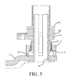
- the lift member 4 moves upwards to the first stopper portion 5 which moves up with the lift member 4 to contact with the second stopper portion 34 of the adjusting part 3, the lift member 4 cannot continue to move up, and the adjusting part 3 that sits on the hinge bracket 2 cannot continue to rotate in the first direction. As shown in FIG. 5 , the lift member 4 moves upwards to the maximum height. The lift member 4 and the door 102 are adjusted to a highest position in the door adjustment range decided by the adjusting part 3.
- the adjusting part 3 that sits on the hinge bracket 2 may be rotated along a second direction (e.g., counterclockwise) opposite to the first direction, and the lift member 4 is driven to move down along the hinge shaft 8, so that the door 102 supported by the lift member 4 moves downwards together.
- a second direction e.g., counterclockwise
- the adjusting part 3 When the lift member 4 directly sits on the hinge bracket 2, if the adjusting part 3 continues to be rotated in the second direction, the adjusting part can move upwards along the second thread portion 41 of the lift member 4 to form spacing with the hinge bracket 2 and hence be suspended, and the lift member 4 remains sitting on the hinge bracket 2. At this time, the adjusting part 3 is in a resting state, and the lift member 4 remains in the lowest position. As stated above, by rotating the adjusting part 3 in the first direction, the suspended adjusting part 3 can be moved downwards along the lift member 4 until the adjusting part contacts with the hinge bracket 2.
- the adjusting part 3 when the height of the door 102 is adjusted, the adjusting part 3 is always in contact with the hinge bracket 2, to drive the lift member 4 to move up or down in the direction of the rotation axis X; moreover, after the lift member 4 reaches the lowest position, the lift member 4 may sit on the hinge bracket 2, and if the adjusting part 3 is rotated along a predetermined direction, the adjusting part 3 may move upwards along the lift member 4 which stands still to the suspended state without bearing the weight of the door 102, thereby avoiding, for example, damage to threads of the adjusting part 3 and the lift member 4 during transport; furthermore, when the lift member 4 moves upwards to the first stopper portion 5 and butts against the second stopper portion 34, the lift member 4 cannot continue to move upwards, thereby avoiding the situation where the adjusting part 3 is rotated excessively to cause the adjusting part 3 and the lift member 4 to fall off.
- the hinge assembly 1 also may be constructed such that the adjusting part 3 adjusts the height of the door 102 from stage to stage according to a predetermined step.
- the upper surface of the hinge bracket 2 has a plurality of concave portions 25 surrounding the shaft fixing hole 24 and disposed at intervals.
- the concave portions 25 can be distributed in a common concentric ring.
- the lower end surface of the adjusting part 3 is provided with a plurality of convex portions 35, and each of the convex portions 35 can be at least partially received in any one of the concave portions 25.
- the adjusting part 3 also may be provided with one concave portion 25 or two convex portions 35 distributed symmetrically about the central axis of the adjusting part 3.
- each of the convex portions 35 moves out of an original concave portion 25 and rotates along the upper surface of the hinge bracket 2, until the convex portion falls into a concave portion 25 adjacent to the original concave portion 25, and this will give an obvious feeling of indication to a user/worker operating the adjusting part.
- each of the shaft fixing holes 24 corresponds to six concave portions 25 distributed at an equal interval.
- each of the convex portions 35 is of an inverted cone shape, and the cone top is chamfered for transition.
- the concave portion 25 may also be constructed as an inverted cone that adapts to matching with the convex portion 35.
- the adjusting part 3 can adjust the height of the door 102 from stage to stage according to a predetermined amplitude; in the event that no large rotation force is applied to the adjusting part 3, the adjusting part 3 does not rotate, that is to say, accidental rotation of the adjusting part 3 can be avoided.
- the concave portions also may be formed on the lower end surface of the adjusting part, and the convex portions are formed on the hinge bracket.
- the first stopper portion 5 is assembled on the lift member 4 as a separate component. However, in an alternative embodiment, it is likely that the first stopper portion is integrally formed on the lift member 4.
- FIG. 1 to FIG. 6 Various embodiments of individual parts described in combination with FIG. 1 to FIG. 6 can be combined in any given manner, so as to achieve the advantages of the present invention.
- the present invention is not limited to the illustrated embodiments, and generally, other means except the illustrated means may also be used as long as the means can achieve the same effect.
Landscapes
- Engineering & Computer Science (AREA)
- Mechanical Engineering (AREA)
- Chemical & Material Sciences (AREA)
- Combustion & Propulsion (AREA)
- Physics & Mathematics (AREA)
- Thermal Sciences (AREA)
- General Engineering & Computer Science (AREA)
- Refrigerator Housings (AREA)
- Hinges (AREA)
Applications Claiming Priority (1)
| Application Number | Priority Date | Filing Date | Title |
|---|---|---|---|
| CN201210486535.5A CN103836873B (zh) | 2012-11-21 | 2012-11-21 | 具有门铰链组件的制冷器具 |
Publications (2)
| Publication Number | Publication Date |
|---|---|
| EP2735680A2 true EP2735680A2 (de) | 2014-05-28 |
| EP2735680A3 EP2735680A3 (de) | 2017-04-19 |
Family
ID=49517374
Family Applications (1)
| Application Number | Title | Priority Date | Filing Date |
|---|---|---|---|
| EP13191404.6A Withdrawn EP2735680A3 (de) | 2012-11-21 | 2013-11-04 | Kältegerät mit Türscharnieranordnung |
Country Status (2)
| Country | Link |
|---|---|
| EP (1) | EP2735680A3 (de) |
| CN (1) | CN103836873B (de) |
Cited By (4)
| Publication number | Priority date | Publication date | Assignee | Title |
|---|---|---|---|---|
| WO2017109648A1 (en) * | 2015-12-23 | 2017-06-29 | BSH Hausgeräte GmbH | Refrigeration appliance |
| CN112922479A (zh) * | 2019-12-05 | 2021-06-08 | 博西华电器(江苏)有限公司 | 冰箱 |
| US20210238900A1 (en) * | 2020-02-03 | 2021-08-05 | Samsung Electronics Co., Ltd. | Refrigerator |
| CN113865226A (zh) * | 2020-06-30 | 2021-12-31 | 青岛海尔电冰箱有限公司 | 安装底脚以及具有其的冰箱 |
Families Citing this family (8)
| Publication number | Priority date | Publication date | Assignee | Title |
|---|---|---|---|---|
| CN104675247A (zh) * | 2015-03-13 | 2015-06-03 | 湖北美的电冰箱有限公司 | 用于制冷设备的下铰链结构和具有其的冰箱 |
| CN104929461A (zh) * | 2015-06-03 | 2015-09-23 | 合肥美的电冰箱有限公司 | 一种调平机构及设有该调平机构的对开门冰箱 |
| CN115822403A (zh) * | 2015-12-19 | 2023-03-21 | 博西华电器(江苏)有限公司 | 制冷器具 |
| CN110736281B (zh) | 2018-07-18 | 2023-01-17 | 博西华电器(江苏)有限公司 | 一种制冷设备 |
| CN112081480B (zh) * | 2019-06-12 | 2023-06-16 | 博西华电器(江苏)有限公司 | 一种用于家用器具的铰链组件及家用器具 |
| CN112747519B (zh) * | 2019-10-31 | 2025-07-08 | 青岛海尔特种电冰柜有限公司 | 门体下垂调节装置及冰箱 |
| CN110748258A (zh) * | 2019-11-05 | 2020-02-04 | 合肥晶弘电器有限公司 | 铰链组件、能调节门体高度的冰箱 |
| CN116696175B (zh) * | 2023-06-28 | 2025-11-21 | Tcl家用电器(合肥)有限公司 | 冰箱的门铰链组件及其制作方法、冰箱 |
Citations (1)
| Publication number | Priority date | Publication date | Assignee | Title |
|---|---|---|---|---|
| CN102365515A (zh) | 2009-02-27 | 2012-02-29 | 伊莱克斯家用产品公司 | 枢转门用可调整铰链 |
Family Cites Families (7)
| Publication number | Priority date | Publication date | Assignee | Title |
|---|---|---|---|---|
| JPH0776967A (ja) * | 1993-09-08 | 1995-03-20 | Murakoshi Mfg Corp | 扉開閉装置 |
| KR200338112Y1 (ko) * | 2003-10-23 | 2004-01-13 | 주식회사 대우일렉트로닉스 | 냉장고 도어 하부 힌지 |
| KR100714549B1 (ko) * | 2004-05-27 | 2007-05-07 | 엘지전자 주식회사 | 냉장고의 힌지장치 |
| KR100750254B1 (ko) * | 2006-09-25 | 2007-08-17 | 주식회사 대우일렉트로닉스 | 높이조절 가능형 냉장고 도어용 힌지 |
| KR101423335B1 (ko) * | 2007-12-12 | 2014-07-28 | 엘지전자 주식회사 | 냉장고 |
| CN101235692A (zh) * | 2007-12-21 | 2008-08-06 | 海信科龙电器股份有限公司 | 一种门铰链装置 |
| KR20110068406A (ko) * | 2009-12-16 | 2011-06-22 | 엘지전자 주식회사 | 냉장고 |
-
2012
- 2012-11-21 CN CN201210486535.5A patent/CN103836873B/zh active Active
-
2013
- 2013-11-04 EP EP13191404.6A patent/EP2735680A3/de not_active Withdrawn
Patent Citations (1)
| Publication number | Priority date | Publication date | Assignee | Title |
|---|---|---|---|---|
| CN102365515A (zh) | 2009-02-27 | 2012-02-29 | 伊莱克斯家用产品公司 | 枢转门用可调整铰链 |
Cited By (5)
| Publication number | Priority date | Publication date | Assignee | Title |
|---|---|---|---|---|
| WO2017109648A1 (en) * | 2015-12-23 | 2017-06-29 | BSH Hausgeräte GmbH | Refrigeration appliance |
| CN112922479A (zh) * | 2019-12-05 | 2021-06-08 | 博西华电器(江苏)有限公司 | 冰箱 |
| US20210238900A1 (en) * | 2020-02-03 | 2021-08-05 | Samsung Electronics Co., Ltd. | Refrigerator |
| US11578519B2 (en) * | 2020-02-03 | 2023-02-14 | Samsung Electronics Co., Ltd. | Refrigerator |
| CN113865226A (zh) * | 2020-06-30 | 2021-12-31 | 青岛海尔电冰箱有限公司 | 安装底脚以及具有其的冰箱 |
Also Published As
| Publication number | Publication date |
|---|---|
| CN103836873A (zh) | 2014-06-04 |
| CN103836873B (zh) | 2018-04-10 |
| EP2735680A3 (de) | 2017-04-19 |
Similar Documents
| Publication | Publication Date | Title |
|---|---|---|
| EP2735680A2 (de) | Kältegerät mit Türscharnieranordnung | |
| EP2735828A1 (de) | Kältegerät mit Türscharnieranordnung | |
| US7685678B2 (en) | Refrigerator having height-adjustable door | |
| EP2972022B1 (de) | Verstellbares scharnier zur montierung einer tür an einem schrank | |
| US9481207B2 (en) | Adjustable sleeve for rolling support device | |
| KR20050028265A (ko) | 냉장고의 선반 높이조절장치 | |
| CN104236219B (zh) | 具有铰链组件的制冷器具 | |
| CN103510775B (zh) | 具有门铰链组件的制冷器具 | |
| US20130249373A1 (en) | Adjustable hinge assembly for a domestic refrigerator | |
| CN104806097A (zh) | 用于冰箱的铰链装置 | |
| KR101241389B1 (ko) | 물품용 높이 조절 받침대 | |
| US6916067B2 (en) | Angle adjusting mechanism for chair | |
| KR101818545B1 (ko) | 내진구조를 갖는 가구용 높이조절장치 및 이를 포함하는 가구 | |
| KR101709554B1 (ko) | 높낮이 고정 기능형 가구용 받침다리 | |
| WO2015037357A1 (ja) | 工具マガジン装置及び工作機械 | |
| JP7333747B2 (ja) | 支柱構造及び昇降式什器 | |
| JP2016037703A (ja) | 可動間仕切り用吊りランナー装置 | |
| KR101720456B1 (ko) | 다리 하단 부품의 연결장치 | |
| JP2020118374A (ja) | 冷蔵庫 | |
| CN103573074A (zh) | 用于冰箱的铰链和具有该铰链的冰箱 | |
| KR101428326B1 (ko) | 토크 가변형 로봇 관절장치 | |
| KR20120107601A (ko) | 냉장고용 캐스터 조립체 | |
| CN220016609U (zh) | 一种凸缘型凸轮分割器 | |
| KR101726287B1 (ko) | 도어 힌지장치 | |
| CN223050082U (zh) | 支撑机构和电器设备 |
Legal Events
| Date | Code | Title | Description |
|---|---|---|---|
| PUAI | Public reference made under article 153(3) epc to a published international application that has entered the european phase |
Free format text: ORIGINAL CODE: 0009012 |
|
| 17P | Request for examination filed |
Effective date: 20131104 |
|
| AK | Designated contracting states |
Kind code of ref document: A2 Designated state(s): AL AT BE BG CH CY CZ DE DK EE ES FI FR GB GR HR HU IE IS IT LI LT LU LV MC MK MT NL NO PL PT RO RS SE SI SK SM TR |
|
| AX | Request for extension of the european patent |
Extension state: BA ME |
|
| RAP1 | Party data changed (applicant data changed or rights of an application transferred) |
Owner name: BSH HAUSGERAETE GMBH |
|
| PUAL | Search report despatched |
Free format text: ORIGINAL CODE: 0009013 |
|
| AK | Designated contracting states |
Kind code of ref document: A3 Designated state(s): AL AT BE BG CH CY CZ DE DK EE ES FI FR GB GR HR HU IE IS IT LI LT LU LV MC MK MT NL NO PL PT RO RS SE SI SK SM TR |
|
| AX | Request for extension of the european patent |
Extension state: BA ME |
|
| RIC1 | Information provided on ipc code assigned before grant |
Ipc: E05F 1/06 20060101ALI20170313BHEP Ipc: E05D 7/081 20060101AFI20170313BHEP Ipc: E05D 7/00 20060101ALI20170313BHEP |
|
| R17P | Request for examination filed (corrected) |
Effective date: 20171019 |
|
| RBV | Designated contracting states (corrected) |
Designated state(s): AL AT BE BG CH CY CZ DE DK EE ES FI FR GB GR HR HU IE IS IT LI LT LU LV MC MK MT NL NO PL PT RO RS SE SI SK SM TR |
|
| GRAP | Despatch of communication of intention to grant a patent |
Free format text: ORIGINAL CODE: EPIDOSNIGR1 |
|
| INTG | Intention to grant announced |
Effective date: 20180720 |
|
| STAA | Information on the status of an ep patent application or granted ep patent |
Free format text: STATUS: THE APPLICATION IS DEEMED TO BE WITHDRAWN |
|
| 18D | Application deemed to be withdrawn |
Effective date: 20181201 |