EP2733014A1 - Seat sliding device for vehicle - Google Patents
Seat sliding device for vehicle Download PDFInfo
- Publication number
- EP2733014A1 EP2733014A1 EP12811993.0A EP12811993A EP2733014A1 EP 2733014 A1 EP2733014 A1 EP 2733014A1 EP 12811993 A EP12811993 A EP 12811993A EP 2733014 A1 EP2733014 A1 EP 2733014A1
- Authority
- EP
- European Patent Office
- Prior art keywords
- rail
- side wall
- lock lever
- parts
- wall parts
- Prior art date
- Legal status (The legal status is an assumption and is not a legal conclusion. Google has not performed a legal analysis and makes no representation as to the accuracy of the status listed.)
- Withdrawn
Links
Images




Classifications
-
- B—PERFORMING OPERATIONS; TRANSPORTING
- B60—VEHICLES IN GENERAL
- B60N—SEATS SPECIALLY ADAPTED FOR VEHICLES; VEHICLE PASSENGER ACCOMMODATION NOT OTHERWISE PROVIDED FOR
- B60N2/00—Seats specially adapted for vehicles; Arrangement or mounting of seats in vehicles
- B60N2/02—Seats specially adapted for vehicles; Arrangement or mounting of seats in vehicles the seat or part thereof being movable, e.g. adjustable
- B60N2/04—Seats specially adapted for vehicles; Arrangement or mounting of seats in vehicles the seat or part thereof being movable, e.g. adjustable the whole seat being movable
- B60N2/06—Seats specially adapted for vehicles; Arrangement or mounting of seats in vehicles the seat or part thereof being movable, e.g. adjustable the whole seat being movable slidable
- B60N2/08—Seats specially adapted for vehicles; Arrangement or mounting of seats in vehicles the seat or part thereof being movable, e.g. adjustable the whole seat being movable slidable characterised by the locking device
- B60N2/0831—Movement of the latch
- B60N2/0837—Movement of the latch pivoting
-
- B—PERFORMING OPERATIONS; TRANSPORTING
- B60—VEHICLES IN GENERAL
- B60N—SEATS SPECIALLY ADAPTED FOR VEHICLES; VEHICLE PASSENGER ACCOMMODATION NOT OTHERWISE PROVIDED FOR
- B60N2/00—Seats specially adapted for vehicles; Arrangement or mounting of seats in vehicles
- B60N2/02—Seats specially adapted for vehicles; Arrangement or mounting of seats in vehicles the seat or part thereof being movable, e.g. adjustable
- B60N2/04—Seats specially adapted for vehicles; Arrangement or mounting of seats in vehicles the seat or part thereof being movable, e.g. adjustable the whole seat being movable
- B60N2/06—Seats specially adapted for vehicles; Arrangement or mounting of seats in vehicles the seat or part thereof being movable, e.g. adjustable the whole seat being movable slidable
- B60N2/07—Slide construction
- B60N2/0702—Slide construction characterised by its cross-section
- B60N2/0705—Slide construction characterised by its cross-section omega-shaped
-
- B—PERFORMING OPERATIONS; TRANSPORTING
- B60—VEHICLES IN GENERAL
- B60N—SEATS SPECIALLY ADAPTED FOR VEHICLES; VEHICLE PASSENGER ACCOMMODATION NOT OTHERWISE PROVIDED FOR
- B60N2/00—Seats specially adapted for vehicles; Arrangement or mounting of seats in vehicles
- B60N2/02—Seats specially adapted for vehicles; Arrangement or mounting of seats in vehicles the seat or part thereof being movable, e.g. adjustable
- B60N2/04—Seats specially adapted for vehicles; Arrangement or mounting of seats in vehicles the seat or part thereof being movable, e.g. adjustable the whole seat being movable
- B60N2/06—Seats specially adapted for vehicles; Arrangement or mounting of seats in vehicles the seat or part thereof being movable, e.g. adjustable the whole seat being movable slidable
- B60N2/07—Slide construction
- B60N2/0722—Constructive details
- B60N2/0727—Stop members for limiting sliding movement
-
- B—PERFORMING OPERATIONS; TRANSPORTING
- B60—VEHICLES IN GENERAL
- B60N—SEATS SPECIALLY ADAPTED FOR VEHICLES; VEHICLE PASSENGER ACCOMMODATION NOT OTHERWISE PROVIDED FOR
- B60N2/00—Seats specially adapted for vehicles; Arrangement or mounting of seats in vehicles
- B60N2/02—Seats specially adapted for vehicles; Arrangement or mounting of seats in vehicles the seat or part thereof being movable, e.g. adjustable
- B60N2/04—Seats specially adapted for vehicles; Arrangement or mounting of seats in vehicles the seat or part thereof being movable, e.g. adjustable the whole seat being movable
- B60N2/06—Seats specially adapted for vehicles; Arrangement or mounting of seats in vehicles the seat or part thereof being movable, e.g. adjustable the whole seat being movable slidable
- B60N2/08—Seats specially adapted for vehicles; Arrangement or mounting of seats in vehicles the seat or part thereof being movable, e.g. adjustable the whole seat being movable slidable characterised by the locking device
- B60N2/0812—Location of the latch
- B60N2/0818—Location of the latch inside the rail
-
- B—PERFORMING OPERATIONS; TRANSPORTING
- B60—VEHICLES IN GENERAL
- B60N—SEATS SPECIALLY ADAPTED FOR VEHICLES; VEHICLE PASSENGER ACCOMMODATION NOT OTHERWISE PROVIDED FOR
- B60N2/00—Seats specially adapted for vehicles; Arrangement or mounting of seats in vehicles
- B60N2/02—Seats specially adapted for vehicles; Arrangement or mounting of seats in vehicles the seat or part thereof being movable, e.g. adjustable
- B60N2/04—Seats specially adapted for vehicles; Arrangement or mounting of seats in vehicles the seat or part thereof being movable, e.g. adjustable the whole seat being movable
- B60N2/06—Seats specially adapted for vehicles; Arrangement or mounting of seats in vehicles the seat or part thereof being movable, e.g. adjustable the whole seat being movable slidable
- B60N2/08—Seats specially adapted for vehicles; Arrangement or mounting of seats in vehicles the seat or part thereof being movable, e.g. adjustable the whole seat being movable slidable characterised by the locking device
- B60N2/0831—Movement of the latch
- B60N2/0862—Movement of the latch sliding
- B60N2/0875—Movement of the latch sliding in a vertical direction
Definitions
- the present invention relates to a seat sliding device for a vehicle, which is to adjust the relative position between a vehicle floor and a seat.
- a seat sliding device for a vehicle disclosed in Patent Document 1 is provided with a lower rail which has an opening that is opened upward, the cross section of which is substantially U-shaped, and an upper rail which blocks the opening, the cross section of which is substantially U-shaped.
- the lower rail engages with the upper rail to slide with each other in a longitudinal direction.
- a lock lever is supported on the upper rail.
- the lock lever is provided with a rivet arranged inside a U-shaped cross section of an attachment part of the lock lever and a spring pin, which penetrates through the attachment part, and also the rivet in a widthwise direction.
- the rivet is crimped and joined to a top plate of the upper rail, by which the lock lever is coupled to the upper rail to rotationally move about the spring pin.
- the lock lever is integrally provided with a latch part which is capable of entering into notches formed at a lower part of the upper rail in association with rotational movement about the spring pin.
- the latch part spreads substantially all over the upper rail in the widthwise direction thereof. Then, a lock hole into which a latched part that is formed on the lower rail can be fitted in association with the rotational movement of the lock lever about the spring pin is formed at the latch part.
- the lock lever is connected to an operating lever which is inserted from a distal end part of the upper rail. Further, a lock spring composed of blade springs is provided with one end part which is held between the top plate of the upper rail and the rivet. The lock lever is pressure-contacted by the other end part of the lock spring and thereby constantly urged in a direction in which the latch part of the lock lever enters into the notches of the upper rail and also in a direction in which the latched part of the lower rail is fitted into the lock hole.
- the lock lever is urged by the lock spring to rotationally move, the latch part thereof enters into the notches of the upper rail and the latched part of the lower rail is also fitted into the lock hole.
- restrictions are placed on movement of the upper rail which supports the lock lever with respect to the lower rail.
- restrictions are placed on movement of a seat with respect to a vehicle floor in the longitudinal direction of the rails. In other words, the seat is locked.
- a release operation force is input from the operating lever.
- the lock lever rotationally moves against an urging force of the lock spring in a direction in which the latch part of the lock lever is detached from the notches of the upper rail and also in a direction in which the latched part of the lower rail is detached from the lock hole, restrictions on movement of the upper rail with respect to the lower rail are released.
- the seat is allowed to move to the vehicle floor in the longitudinal direction of the rails. In other words, the seat is unlocked.
- a seat sliding device for a vehicle disclosed in Patent Document 2 is provided with a lower rail which has a flange part and an upper rail which holds the flange part.
- a cut is formed at a top plate part near both ends of the upper rail and a cut-out part is also formed at each end of an inner edge of the flange part of the lower rail.
- the distal end part of the lock spring is fixed to the upper rail, that is, the top plate at a position of a rotating shaft of the lock lever, that is, at a position of the rivet. That is, the lock spring is such that at least an end part which serves as a fixed end thereof is restricted to a position of the rotating shaft of the lock lever. Due to the above restriction, there may be found a case where length of the lock spring in relation to a spring constant of the lock spring on bending deformation (effective length) is not sufficiently secured. In this case, the spring constant is required to be increased due to a decrease in length of the lock spring. In association with the decrease, for example, an increase in operating force required for releasing the operating lever may deteriorate the operation performance of the lever.
- the folded part of the upper rail restricts relative movement between the lower rail and the upper rail, while supporting them in a cantilever state. Therefore, the folded part is required to increase, for example, the thickness of the upper rail.
- a seat sliding device for a vehicle which is provided with a lower rail 91 having a pair of side wall parts 91 a arranged in the widthwise direction in parallel, the cross section of which is substantially C-shaped, and an upper rail 92, which is attached inside the lower rail 91 and is able to move relatively with respect to the lower rail 91.
- both end parts of a lock pin 93 which bridges the lower rail 91 in the widthwise direction to cut across a movement trajectory of a distal end surface 92a of the upper rail 92, are individually joined to the side wall parts 91 a.
- the distal end surface 92a of the upper rail 92 is brought into contact with and latched to the lock pin 93, by which a distance of relative movement between the lower rail 91 and the upper rail 92 is restricted within a predetermined range. Since the lock pin 93 restricts movement of the upper rail 92 while supporting the lower rail 91 on both sides, strength can be sufficiently secured.
- a range of restricting the distance of relative movement between the lower rail 91 and the upper rail 92 is determined by a distance between the distal end surface 92a and the lock pin 93 in a direction in which the upper rail 92 moves, that is, the length of the upper rail 92 in this direction, for example, where the lock pin 93 on the lower rail 91 is fixed to a certain position.
- this lower rail 91 also undergoes an automatic change in a range of restricting the distance of relative movement between the lower rail 91 and the upper rail 92.
- An object of the present invention is to provide a seat sliding device for a vehicle which is capable of decreasing restrictions on an arrangement space and also suppressing an increase in operating force required for disengaging a lock lever from a rail.
- Another object of the present invention is to provide a seat sliding device for a vehicle which is capable of more securely restricting relative movement between rails without a decrease in degree of freedom in terms of adjusting a range of restricting a distance of relative movement between the rails.
- a first aspect of the present invention provides a seat sliding device for a vehicle including a first rail, a second rail, a rotating shaft, a lock lever, and an urging member.
- the first rail is adapted to be fixed to one of a vehicle floor and a seat.
- the second rail is adapted to be fixed to the other one of the vehicle floor and the seat and coupled to the first rail to make a relative movement with respect to the first rail.
- the second rail has a pair of side wall parts arranged in a widthwise direction in parallel and a coupling wall part, which couples base ends of the side wall parts in which the base ends of the side wall parts are spaced away from the first rail.
- the rotating shaft has an axis extending in the widthwise direction and which bridges the side wall parts.
- the lock lever has a pair of vertical wall parts that are arranged in parallel between the side wall parts in the widthwise direction and through which the rotating shaft penetrates.
- the lock lever rotationally moves about the axis in one direction to engage with the first rail, thereby restricting relative movement between the first rail and the second rail and rotationally moves about the axis in the other direction to release the engagement with the first rail, thereby releasing restrictions on the relative movement.
- the urging member has a latch part latched to the coupling wall part and a latch end part latched to the lock lever.
- the urging member generates in association with bending deformation an urging force that urges the lock lever in a vertical direction in which the lock lever engages with the first rail.
- the urging member has a coil part, which is wound about the rotating shaft between the latch part and the latch end part.
- a second aspect of the present invention provides a seat sliding device for a vehicle which is arranged on a vehicle having a floor and a seat.
- the seat sliding device for a vehicle includes a first rail, a second rail, a rotating shaft, a lock lever, and an urging member.
- the first rail is adapted to be fixed to one of the floor and the seat.
- the second rail is adapted to be fixed to the other one of the floor and the seat and coupled to the first rail to make relative movement with respect to the first rail.
- the second rail has a pair of first supporting parts arranged in parallel in a widthwise direction of the vehicle and a coupling part, which couples the base ends of the pair of first supporting parts in which the base ends of the pair of first supporting parts are spaced away from the first rail.
- the rotating shaft has an axis extending in the widthwise direction of the vehicle and is supported between the first supporting parts to rotate.
- the lock lever has a pair of second supporting parts that are arranged in parallel between the first supporting parts in the widthwise direction of the vehicle and through which the rotating shaft penetrates.
- the urging member has a latch part latched to the coupling wall part, a latch end part latched to the lock lever, and a coil part wound about the rotating shaft between the latch part and the latch end part, thereby generating in association with bending deformation an urging force for urging the lock lever in a vertical direction of the vehicle so that the lock lever engages with the first rail.
- the lock lever When the lock lever rotates about the axis in one direction, the lock lever engages with the first rail to prevent relative movement between the first rail and the second rail, and when the lock lever rotates about the axis in the other direction, the first rail is released from the engagement with the lock lever, thereby allowing the relative movement.
- a third aspect of the present invention provides a seat sliding device for a vehicle which is installed on a vehicle having a floor and a seat.
- the seat sliding device for a vehicle includes a first rail, a second rail, and a latch member.
- the first rail is adapted to be fixed to one of the floor and the seat.
- the second rail is adapted to be fixed to the other one of the floor and the seat and coupled to the first rail to make relative movement with respect to the first rail.
- the first rail is provided with a pair of first side wall parts arranged in a widthwise direction in parallel, two first folded wall parts, which individually extend inward in the widthwise direction facing each other from distal ends of the first side wall parts and folded toward the base ends of the first side wall parts, and a restriction part further extending from distal end of the first folded wall part at a predetermined position of the first rail in the longitudinal direction.
- the second rail is provided with a pair of second side wall parts arranged in parallel between the first side wall parts in the widthwise direction, two second folded wall parts extending individually outward in the widthwise direction mutually spaced away from distal ends of the second side wall parts and folded to be enclosed with the first side wall parts and the first folded wall parts, and a side wall part attachment hole and a folded wall part attachment hole, which are formed to respectively face in the widthwise direction the second side wall parts and the second folded wall parts are adjacent at a predetermined position of the second rail in the longitudinal direction.
- the latch member is inserted into the side wall part attachment hole and the folded wall part attachment hole to bridge the second side wall parts and the second folded wall parts in the widthwise direction, opens a movement trajectory of the first folded wall part in a direction in which the first rail and the second rail make relative movement, and cuts across a movement trajectory of the restriction part.
- the lock lever is urged in the vertical direction to engage with the first rail by an urging force in association with bending deformation of the urging member.
- the effective length of the urging member in relation to a spring constant on bending deformation is determined by a length between a latch position to the coupling wall part (latch part) and the rotating shaft, a length between a lock position to the lock lever (latch end part) and the rotating shaft, and a length of the coil part. It is, therefore, possible to decrease a spring constant of the urging member on bending deformation only by the length of the coil part.
- a lower rail 3 as a first rail is fixed on a vehicle floor 2 in such a manner to extend in the back and forth direction of a vehicle.
- An upper rail 4 as a second rail is attached to the lower rail 3 to make relative movement with respect to the lower rail 3 in the back and forth direction.
- a pair of the lower rail 3 and the upper rail 4 shown in Fig. 1 is one of two pairs placed in the widthwise direction of the vehicle (a direction orthogonal to the space in Fig. 1 ), with an interval therebetween.
- the pair arranged on the left side with respect to the front.
- a seat 5 on which a passenger sits is fixed and supported on the upper rails 4.
- Normally, relative movement of the upper rail 4 with respect to the lower rail 3 is kept restricted in principle.
- a release handle 6 which releases the restricted state.
- the lower rail 3 is provided with a pair of first side wall parts 11, which are composed of plate members and vertically extend to both sides in the widthwise direction and a first coupling wall part 12, which couples the base ends of the first side wall parts 11, that is, both lower ends.
- a first folded wall part 13 which extends internally in the widthwise direction and is folded toward the base end of each of the first side wall parts 11 is formed at a distal end of each of the first side wall parts 11, that is, at an upper end thereof, to continue to the first side wall part 11.
- the upper rail 4 is provided with second side wall parts 14 (first supporting parts) as a pair of side wall parts which are composed of plate members and vertically extend between the first folded wall parts 13 of the lower rail 3 and a second coupling wall part 15 (coupling part) as a coupling wall part that couples the base ends of the second side wall parts 14 in which the base ends of the second side wall parts 14 are spaced away from the lower rail 3, that is, both upper ends thereof, as shown together in Fig. 4(a) to Fig. 4(c) .
- a second folded wall part 16 which extends outward in the widthwise direction and is folded to be enclosed by the first side wall part 11, and the first folded wall part 13 is formed at a distal end of each of the second side wall parts 14, that is, at a lower end thereof, in such a manner to continue to the second side wall part 14.
- each of the lower rail 3 and the upper rail 4 is provided with a substantially U-shaped cross section, and these rails are butted together so that their opening parts face each other.
- the rails are prevented from being detached in the vertical direction mainly by engagement between the first folded wall parts 13 and the second folded wall parts 16.
- the lower rail 3 and the upper rail 4 configure a rail cross section which assumes substantially a rectangular box shape.
- the lower rail 3 configures an inner space S together with the upper rail 4.
- a pair of rolling members 20 are attached in the back and forth direction between each of the second folded wall parts 16 and each of the first side wall parts 11 which faces thereto.
- the upper rail 4 is supported to be slidable with respect to the lower rail 3 in the longitudinal direction (in the back and forth direction) in such a manner that the rolling members 20 are rolled between the upper rail 4 and the lower rail 3.
- Rectangular tooth-like lock pawls 13b are individually formed between adjacent notches 13a.
- the plurality of lock pawls 13b are arranged in parallel in the longitudinal direction of the lower rail 3, with the above-described predetermined interval kept therebetween.
- all the plurality of lock pawls 13b are arranged to be held between the restriction parts 17 of the lower rail 3 (first folded wall parts 13) in the longitudinal direction.
- Two side wall part attachment holes 14a are formed at an intermediate part of each of the second side wall parts 14 of the upper rail 4 in the longitudinal direction, with an interval therebetween in this direction. Further, as also shown in Fig. 4(a) , a folded wall part attachment hole 16a is formed at each of the second folded wall parts 16 of the upper rail 4 to face each of the side wall part attachment holes 14a in the widthwise direction.
- the side wall part attachment hole 14a and the folded wall part attachment hole 16a are arranged in the vertical direction between the lower end of the first folded wall part 13 (lock pawl 13b) and the lower end of the restriction part 17.
- a latch member 40 is inserted into the side wall part attachment hole 14a and the folded wall part attachment hole 16a adjacent to each other in the widthwise direction in a manner to bridge the second side wall part 14 and the second folded wall part 16 in the widthwise direction.
- the latch member 40 is made of, for example, a blade spring prepared by folding a metal plate member into a U-shape.
- the latch member 40 is integrally provided with a pair of engagement pieces 41 which spread substantially parallel to each other and a substantially semi-cylindrical coupling part 42 for connecting the engagement pieces 41.
- each engagement piece 41 there is formed a retaining part 43 which is cut and extended outward to be spaced away from each other, with the vicinity of the coupling part 42 given as a base end.
- a vertical distance between the end parts 41 a of the engagement pieces 41 is set slightly larger than a vertical distance between both inner wall surfaces of the side wall part attachment holes 14a.
- the latch member 40 When the latch member 40 is assembled to the upper rail 4, the lower rail 3 and the upper rail 4 are assembled in advance so that the side wall part attachment hole 14a and the folded wall part attachment hole 16a are arranged between the restriction parts 17 in the longitudinal direction. As shown in Fig. 6 , in this state, the latch member 40 is sequentially inserted into the side wall part attachment hole 14a and the folded wall part attachment hole 16a from inside the upper rail 4 outward in the widthwise direction. That is, the latch member 40 is sequentially inserted into the side wall part attachment hole 14a and the folded wall part attachment hole 16a, with the coupling part 42 kept ahead.
- the engagement pieces 41 or the retaining parts 43 are pressed to inner wall surface parts facing each other in the vertical direction which are inner wall surfaces of the side wall part attachment hole 14a, by which the latch member 40 undergoes elastic deformation so that the engagement pieces 41 are closed in this direction.
- the coupling part 42 penetrates through the folded wall part attachment hole 16a and also the retaining parts 43 pass through the side wall part attachment hole 14a. Therefore, the retaining parts 43 are released from both vertical inner wall surfaces of the side wall part attachment hole 14a, by which the latch member 40 resumes elasticity to open the engagement pieces 41 in the vertical direction.
- each of the retaining parts 43 engages with an edge part of the side wall part attachment hole 14a in a direction reverse to an insertion direction into the side wall part attachment hole 14a (that is, inward in the widthwise direction), thereby the latch member 40 is suppressed from being detached from the upper rail 4. Accordingly, end parts 41a of the engagement pieces 41 are pressure-contacted to the vertical inner wall surfaces of the side wall part attachment hole 14a, by which the latch member 40 is retained on the upper rail 4.
- the latch member 40 bridges the second side wall part 14 and the second folded wall part 16 in the widthwise direction opens a movement trajectory of the first folded wall part 13, and cuts across a movement trajectory of the restriction part 17 in a direction in which the lower rail 3 and the upper rail 4 make relative movement. Therefore, when the lower rail 3 and the upper rail 4 make relative movement, the corresponding restriction part 17 and the latch member 40 are brought into contact to restrict the movement.
- the latch member 40 is in contact with the restriction part 17 on an end surface 41 b in the back and forth direction thereof, that is, in a direction orthogonal to the vertical direction that is the thickness direction of the engagement pieces 41. Thereby, a distance of relative movement between the lower rail 3 and the upper rail 4 is restricted within a predetermined range.
- a circular shaft attachment hole 16b which is located further forward than the folded wall part attachment hole 16a on the front side is formed at each of the second folded wall parts 16 of the upper rail 4.
- a pair of slit-like supporting holes 21 which are arranged in the widthwise direction in parallel further forward than the shaft attachment hole 16b are formed on the second coupling wall part 15 of the upper rail 4. Both supporting holes 21 extend in the back and forth direction.
- a circular shaft attachment hole 14b which is concentric with the shaft attachment hole 16b is formed at each of the second side wall parts 14 of the upper rail 4.
- a fan-shaped through hole 14c centering on the shaft attachment hole 14b in an intermediate part between the side wall part attachment holes 14a is formed at each of the second side wall parts 14.
- the shaft attachment holes 14b, 16b are mutually equal in inner diameter, and the through holes 14c, 16c are, as also shown in Fig. 4(b) , mutually similar in opening shape and face in the widthwise direction.
- a lock lever 30 is coupled inside the upper rail 4 by a cylindrical support pin 22, which is a rotating shaft with a center line (axis) extending in the widthwise direction to rotate. That is, as shown in Fig. 2 , the lock lever 30 is provided with a handgrip part 31 composed of a plate member extending in the back and forth direction.
- the handgrip part 31 is extended in such a manner that two vertical wall parts 32 (second supporting parts) are arranged in parallel in the widthwise direction all over the length thereof in the longitudinal direction.
- a distance between the vertical wall parts 32 in the widthwise direction is set smaller than a distance between the second side wall parts 14 of the upper rail 4 in the widthwise direction.
- each of the vertical wall parts 32 is such that an upper end edge space is connected in the widthwise direction by a retention wall 33 at each of the front end parts and the upper end edge space is also connected in the widthwise direction by a top plate part 34 at each of the rear end parts.
- a circular shaft attachment hole 35 which is concentric with the support pin 22 (shaft attachment holes 14b, 16b) is formed at each of the vertical wall parts 32.
- the support pins 22, the ends of which are inserted into the shaft attachment holes 14b, 16b, are inserted into and supported by the shaft attachment holes 35, by which the handgrip part 31 is coupled to the upper rail 4 to rotate.
- each of the vertical wall parts 32 is provided with a flange-shaped supporting wall 32a which protrudes internally in the widthwise direction and facing each other from a lower end edge between the retention wall 33 and the shaft attachment hole 35 in the back and forth direction.
- a pair of joining parts 36 protrude at each of the vertical wall parts 32 downward from a lower end of the rear end part thereof which is below the top plate part 34, with an interval kept therebetween in the back and forth direction.
- Each of the joining parts 36 is configured so that a pair of joining pieces 36a, 36b arranged to be adjacent in the back and forth direction are given as one set.
- the lock lever 30 is provided with a flat-plate like lock plate 37 which spreads in the back and forth direction and in the widthwise direction in such a manner to penetrate through the through holes 14c, 16c.
- Four slit-like joining holes 38 which open in the vertical direction to face the respective joining parts 36 are formed on the lock plate 37.
- the lock plate 37 is joined and fixed to the handgrip part 31 by crimping the distal ends of the joining pieces 36a, 36b which penetrate through the joining hole 38, for example, to open in the back and forth direction after insertion of the joining part 36 into each of the joining holes 38.
- each of the lock holes 39 is opened in the vertical direction to face the first folded wall part 13 and arranged at a position that can be in alignment with each of a plurality of lock pawls 13b (three pawls) adjacent in the longitudinal direction of the lower rail 3.
- each of the lock holes 39 is able to accept a corresponding lock pawl 13b.
- restrictions are placed on relative movement between the lower rail 3 and the upper rail 4.
- the chain double-dashed line in Fig. 4(b) when the lock lever 30 rotationally moves about the support pin 22 so that the lock plate 37 descends, each of the lock holes 39 is detached from the corresponding lock pawl 13b. At this time, restrictions on relative movement between the lower rail 3 and the upper rail 4 are released.
- a wire spring 50 composed of one linear element as an urging member is arranged inside the upper rail 4.
- the wire spring 50 is substantially U-shaped and opened backward in a planar view.
- the wire spring 50 is provided with a pair of extension parts 51 which are symmetrical and extend in the back and forth direction and a connection part 52 which connects the front ends of the extension parts 51 in the widthwise direction.
- each of the extension parts 51 is provided with a fixing part 53 (latch part) at which an intermediate part in the longitudinal direction is curved out upward and also provided with a coil part 54 which is wound clockwise backward at the rear side of the fixing part 53.
- the wire spring 50 configures a first urging part 55 at a site further backward than the fixing part 53 of each of the extension parts 51 including the coil part 54 and also forms a second urging part 56 at a site further forward than the connection part 52 and the fixing part 53 of each of the extension parts 51.
- the wire spring 50 is arranged substantially inside the handgrip part 31 in such a manner that each of the fixing parts 53 is allowed to protrude from a corresponding supporting hole 21 of the upper rail 4. Further, the coil part 54 is wound about the support pin 22, by which the wire spring 50 is supported by the upper rail 4 (the second side wall parts 14).
- the wire spring 50 is such that each of the fixing parts 53 is brought into contact with the rear end surface of the supporting hole 21, and the rear end part of the first urging part 55 is elastically brought into contact with the lower surface of the lock plate 37 further backward than the coil part 54 (support pin 22).
- the first urging part 55 is subjected to bending deformation including the coil part 54, with a position which fixes the upper rail 4 (fixing part 53) given as a supporting point, and urging the lock lever 30 by using the fixing position as the supporting point. Therefore, the lock lever 30 is urged by the wire spring 50 (first urging part 55) to rotationally move in a direction in which the lock plate 37 ascends, that is, in a direction in which a lock pawl 13b corresponding to each lock hole 39 is fitted.
- the upper surface of the handgrip part 31 (top plate part 34) is brought into contact with the lower surface of the second coupling wall part 15, thereby placing restrictions on a rotational movement of the lock plate 37.
- the coil part 54 is placed at the first urging part 55. This is because an elastic coefficient (spring constant) on bending deformation is practically reduced, while the extension length of the first urging part 55 is suppressed in the back and forth direction.
- the fixing parts 53 of the wire spring 50 are kept out of contact with the front end surface of the supporting hole 21. Then, the connection part 52 of the wire spring 50 (second urging part 56) is arranged further forward than the retention wall 33.
- the release handle 6 is made by bending a tubular member and formed to bridge the upper rails 4 at the front side thereof in the widthwise direction. As shown in Fig. 2 , a distal end part 61 extending at the back of the release handle 6 assumes a cylindrical shape, the outer diameter of which is smaller than a distance between the vertical wall parts 32 in the widthwise direction. And, a slit-like supporting groove 62 extending in the widthwise direction is formed at the lower part of the distal end part 61.
- the release handle 6 is inserted below the retention wall 33 of the handgrip part 31 (lock lever 30) to which each of the distal end parts 61 corresponds and above the supporting walls 32a, that is, between the vertical wall parts 32. Then, the distal end part 61 is latched and retained by the connection part 52 of the wire spring 50 (the second urging part 56) which is fitted into the supporting groove 62. That is, the rear end surface 62a of the supporting groove 62 is given as an engagement surface with the connection part 52 for suppressing detachment of the distal end part 61 of the release handle 6.
- the distal end part 61 inserted between the vertical wall parts 32 is arranged to face the support pin 22 on a backward extension line thereof. Thereby, even where the distal end part 61 is excessively inserted between the vertical wall parts 32, it is restricted to a predetermined range until the distal end part 61 is in contact with the support pin 22.
- the distal end part 61 inserted between the vertical wall parts 32 is urged on the supporting groove 62 by the wire spring 50 (second urging part 56) to ascend.
- the distal end part 61 is retained to make an integral rotation with the lock lever 30 substantially about the support pin 22 in such a manner that upper and lower parts of the distal end part 61 are respectively brought into contact with a lower surface of the retention wall 33 and upper surfaces of the supporting walls 32a.
- the wire spring 50 is also provided with functions to keep the release handle 6 elastically so that the release handle 6 makes an integral rotation with the lock lever 30.
- the distal end part 61 (release handle 6) is elastically retained at the connection part 52 of the wire spring 50.
- the lock lever 30 is coupled, with an appropriate clearance kept.
- this is because when the distal end part 61 (release handle 6) tries to make rotational movement about the support pin 22 in a direction reverse to an original operating direction due to an unintended external force, etc., the distal end part 61 is allowed to sway with respect to the lock lever 30, thereby avoiding an excessively large load on the lock lever 30.
- the connection part 52 of the wire spring 50 (second urging part 56) which latches the distal end part 61 of the release handle 6 is arranged further forward than the retention wall 33. This is because the release handle 6 is suppressed from swaying about the connection part 52 with respect to the lock lever 30.
- the release handle 6 is assumed to be released from an operating force thereof.
- the wire spring 50 generates in association with bending deformation an urging force which urges the lock lever 30 in the vertical direction toward a direction in which the lock lever 30 engages with the lower rail 3.
- the lock lever 30 is allowed to rotationally move by an urging force of the wire spring 50 (the first urging part 55) in a direction in which the lock plate 37 ascends about the support pin 22 integrally with the distal end part 61 (release handle 6), that is, in a direction in which a corresponding lock pawl 13b is fitted into each of the lock holes 39.
- the release handle 6 is assumed to be operated to raise a front end thereof.
- the lock lever 30 against the urging force of the wire spring 50 (the first urging part 55), the lock lever 30 is allowed to rotationally move integrally with the distal end part 61 (release handle 6) in a direction in which the lock plate 37 descends about the support pin 22, that is, to a side where each of the lock holes 39 is detached from a corresponding lock pawl 13b.
- restrictions on relative movement between the lower rail 3 and the upper rail 4 are released in the above-described manner. Then, it is possible to adjust a position of the seat 5 supported by the upper rail 4 in the back and forth direction.
- the wire spring 50 (the first urging part 55) is decreased in spring constant on bending deformation only by length of the coil part 54. Therefore, the release handle 6 is also decreased in operating force required for release operation at this time.
- the restriction part 17 is brought into contact with the latch member 40 in the above-described manner, thereby restricting the movement. Accordingly, a distance of relative movement between the lower rail 3 and the upper rail 4 is restricted within a predetermined range.
- the latch member 40 is brought into contact with the restriction part 17 in a state of being supported by the upper rail 4 on both sides, thereby more securely restricting the movement.
- the latch member 40 is supported on both sides by the second side wall parts 14 and the second folded wall parts 16 which are adjacent in the widthwise direction of the upper rail 4.
- the present embodiment is able to provide the following effects.
- the wire spring 50 (the first and second urging parts 55, 56) is configured only with a single extension part 51.
- the wire spring 50 is formed with a linear element having a circular cross section or formed with a linear element having a rectangular cross section (what is called a band material).
- an urging member which urges the lock lever 30 and a member which retains the release handle 6 (the distal end part 61) are provided separately.
- the support pin 22 is supported by the lock lever 30 (the vertical wall parts 32), with the end parts thereof fixed to the upper rail 4 (the second side wall parts 14), or fixed to the lock lever 30 (the vertical wall parts 32), with the end parts thereof pivotally supported by the upper rail 4 (the second side wall parts 14).
- the lower rail 3 or the upper rail 4 is configured by a plurality of plate members that are connected by welding, etc.
- the lower rail 3 and the upper rail 4 are in such a configuration that one each is placed or three or more each are placed with respect to the seat 5.
- the seat moves in the widthwise direction of the seat, for example.
- a retaining part of the latch member 40 is such that it engages with an edge part of the folded wall part attachment hole 16a, thereby suppressing detachment from the upper rail 4.
- the latch member 40 is assembled to the upper rail 4 to support the restriction part 17 on an end surface in the thickness direction.
- the latch member 40 to be arranged on the upper rail 4 is provided solely on one side of the upper rail 4 in the widthwise direction.
- restriction part 17 and the latch member 40 are placed only on one side of each of the lower rail 3 and the upper rail 4 in the widthwise direction.
- restriction part 17 is arranged at an intermediate part of the lower rail 3 (the first folded wall part 13) in the longitudinal direction and also the latch member 40 is arranged at both end parts of the upper rail 4 in the longitudinal direction.
- restriction part 17 arranged on one side of the lower rail 3 in the widthwise direction is provided solely or in a pair arranged in the longitudinal direction, with an interval kept therebetween.
- the latch member is a flat and plate-like or a wedge-like latch member in which both end parts thereof are press-fitted or welded into the side wall part attachment hole 14a and the folded wall part attachment hole 16a mutually adjacent in the widthwise direction and bridging the second side wall part 14 and the second folded wall part 16.
Landscapes
- Engineering & Computer Science (AREA)
- Aviation & Aerospace Engineering (AREA)
- Transportation (AREA)
- Mechanical Engineering (AREA)
- Seats For Vehicles (AREA)
Abstract
Description
- The present invention relates to a seat sliding device for a vehicle, which is to adjust the relative position between a vehicle floor and a seat.
- There have been so far proposed various types of a seat sliding device for a vehicle. For example, a seat sliding device for a vehicle disclosed in Patent Document 1 is provided with a lower rail which has an opening that is opened upward, the cross section of which is substantially U-shaped, and an upper rail which blocks the opening, the cross section of which is substantially U-shaped. The lower rail engages with the upper rail to slide with each other in a longitudinal direction. And, a lock lever is supported on the upper rail.
- That is, the lock lever is provided with a rivet arranged inside a U-shaped cross section of an attachment part of the lock lever and a spring pin, which penetrates through the attachment part, and also the rivet in a widthwise direction. The rivet is crimped and joined to a top plate of the upper rail, by which the lock lever is coupled to the upper rail to rotationally move about the spring pin.
- The lock lever is integrally provided with a latch part which is capable of entering into notches formed at a lower part of the upper rail in association with rotational movement about the spring pin. The latch part spreads substantially all over the upper rail in the widthwise direction thereof. Then, a lock hole into which a latched part that is formed on the lower rail can be fitted in association with the rotational movement of the lock lever about the spring pin is formed at the latch part.
- The lock lever is connected to an operating lever which is inserted from a distal end part of the upper rail. Further, a lock spring composed of blade springs is provided with one end part which is held between the top plate of the upper rail and the rivet. The lock lever is pressure-contacted by the other end part of the lock spring and thereby constantly urged in a direction in which the latch part of the lock lever enters into the notches of the upper rail and also in a direction in which the latched part of the lower rail is fitted into the lock hole.
- Therefore, the lock lever is urged by the lock spring to rotationally move, the latch part thereof enters into the notches of the upper rail and the latched part of the lower rail is also fitted into the lock hole. Thereby, restrictions are placed on movement of the upper rail which supports the lock lever with respect to the lower rail. Accordingly, restrictions are placed on movement of a seat with respect to a vehicle floor in the longitudinal direction of the rails. In other words, the seat is locked.
- On the other hand, a release operation force is input from the operating lever. Thereby, when the lock lever rotationally moves against an urging force of the lock spring in a direction in which the latch part of the lock lever is detached from the notches of the upper rail and also in a direction in which the latched part of the lower rail is detached from the lock hole, restrictions on movement of the upper rail with respect to the lower rail are released. Thereby, the seat is allowed to move to the vehicle floor in the longitudinal direction of the rails. In other words, the seat is unlocked.
- As so far described, it is possible to adjust and retain the seat at such a required position, at which a passenger sits favorably.
- Further, for example, a seat sliding device for a vehicle disclosed in Patent Document 2 is provided with a lower rail which has a flange part and an upper rail which holds the flange part. A cut is formed at a top plate part near both ends of the upper rail and a cut-out part is also formed at each end of an inner edge of the flange part of the lower rail. In the above-described structure, when the lower rail and the upper rail are assembled, the cut of the upper rail is folded inward after insertion of the lower rail into the upper rail to form a folded part. Then, on movement of the upper rail with respect to the lower rail, the folded part of the upper rail is brought into contact with and latched to a step which is formed by the cut-out part of the lower rail. Thereby, a distance of relative movement between the lower rail and the upper rail is restricted within a predetermined range.
-
- Patent Document 1:
Japanese Patent No. 4355963 - Patent Document 2:
Japanese Utility Model Publication No. 58-19836 - Regarding the lock spring composed of blade springs for urging the lock lever, the distal end part of the lock spring is fixed to the upper rail, that is, the top plate at a position of a rotating shaft of the lock lever, that is, at a position of the rivet. That is, the lock spring is such that at least an end part which serves as a fixed end thereof is restricted to a position of the rotating shaft of the lock lever. Due to the above restriction, there may be found a case where length of the lock spring in relation to a spring constant of the lock spring on bending deformation (effective length) is not sufficiently secured. In this case, the spring constant is required to be increased due to a decrease in length of the lock spring. In association with the decrease, for example, an increase in operating force required for releasing the operating lever may deteriorate the operation performance of the lever.
- On the other hand, in Patent Document 2, the folded part of the upper rail restricts relative movement between the lower rail and the upper rail, while supporting them in a cantilever state. Therefore, the folded part is required to increase, for example, the thickness of the upper rail.
- Thus, as shown in
Fig. 8(a) and Fig. 8(b) , there is proposed a seat sliding device for a vehicle which is provided with alower rail 91 having a pair ofside wall parts 91 a arranged in the widthwise direction in parallel, the cross section of which is substantially C-shaped, and anupper rail 92, which is attached inside thelower rail 91 and is able to move relatively with respect to thelower rail 91. In this case, both end parts of alock pin 93, which bridges thelower rail 91 in the widthwise direction to cut across a movement trajectory of adistal end surface 92a of theupper rail 92, are individually joined to theside wall parts 91 a. Therefore, when theupper rail 92 moves to thelower rail 91, thedistal end surface 92a of theupper rail 92 is brought into contact with and latched to thelock pin 93, by which a distance of relative movement between thelower rail 91 and theupper rail 92 is restricted within a predetermined range. Since thelock pin 93 restricts movement of theupper rail 92 while supporting thelower rail 91 on both sides, strength can be sufficiently secured. - However, in the above-described structure, a range of restricting the distance of relative movement between the
lower rail 91 and theupper rail 92 is determined by a distance between thedistal end surface 92a and thelock pin 93 in a direction in which theupper rail 92 moves, that is, the length of theupper rail 92 in this direction, for example, where thelock pin 93 on thelower rail 91 is fixed to a certain position. In other words, when theupper rail 92 which is attached to thelower rail 91 is changed in length, thislower rail 91 also undergoes an automatic change in a range of restricting the distance of relative movement between thelower rail 91 and theupper rail 92. As a result, there is a significant decrease in degree of freedom in terms of adjusting a range of restricting the distance of relative movement between thelower rail 91 and theupper rail 92. - An object of the present invention is to provide a seat sliding device for a vehicle which is capable of decreasing restrictions on an arrangement space and also suppressing an increase in operating force required for disengaging a lock lever from a rail.
- Another object of the present invention is to provide a seat sliding device for a vehicle which is capable of more securely restricting relative movement between rails without a decrease in degree of freedom in terms of adjusting a range of restricting a distance of relative movement between the rails.
- In order to attain the above objects, a first aspect of the present invention provides a seat sliding device for a vehicle including a first rail, a second rail, a rotating shaft, a lock lever, and an urging member. The first rail is adapted to be fixed to one of a vehicle floor and a seat. The second rail is adapted to be fixed to the other one of the vehicle floor and the seat and coupled to the first rail to make a relative movement with respect to the first rail. The second rail has a pair of side wall parts arranged in a widthwise direction in parallel and a coupling wall part, which couples base ends of the side wall parts in which the base ends of the side wall parts are spaced away from the first rail. The rotating shaft has an axis extending in the widthwise direction and which bridges the side wall parts. The lock lever has a pair of vertical wall parts that are arranged in parallel between the side wall parts in the widthwise direction and through which the rotating shaft penetrates. The lock lever rotationally moves about the axis in one direction to engage with the first rail, thereby restricting relative movement between the first rail and the second rail and rotationally moves about the axis in the other direction to release the engagement with the first rail, thereby releasing restrictions on the relative movement. The urging member has a latch part latched to the coupling wall part and a latch end part latched to the lock lever. The urging member generates in association with bending deformation an urging force that urges the lock lever in a vertical direction in which the lock lever engages with the first rail. The urging member has a coil part, which is wound about the rotating shaft between the latch part and the latch end part.
- A second aspect of the present invention provides a seat sliding device for a vehicle which is arranged on a vehicle having a floor and a seat. The seat sliding device for a vehicle includes a first rail, a second rail, a rotating shaft, a lock lever, and an urging member. The first rail is adapted to be fixed to one of the floor and the seat. The second rail is adapted to be fixed to the other one of the floor and the seat and coupled to the first rail to make relative movement with respect to the first rail. The second rail has a pair of first supporting parts arranged in parallel in a widthwise direction of the vehicle and a coupling part, which couples the base ends of the pair of first supporting parts in which the base ends of the pair of first supporting parts are spaced away from the first rail. The rotating shaft has an axis extending in the widthwise direction of the vehicle and is supported between the first supporting parts to rotate. The lock lever has a pair of second supporting parts that are arranged in parallel between the first supporting parts in the widthwise direction of the vehicle and through which the rotating shaft penetrates. The urging member has a latch part latched to the coupling wall part, a latch end part latched to the lock lever, and a coil part wound about the rotating shaft between the latch part and the latch end part, thereby generating in association with bending deformation an urging force for urging the lock lever in a vertical direction of the vehicle so that the lock lever engages with the first rail. When the lock lever rotates about the axis in one direction, the lock lever engages with the first rail to prevent relative movement between the first rail and the second rail, and when the lock lever rotates about the axis in the other direction, the first rail is released from the engagement with the lock lever, thereby allowing the relative movement.
- A third aspect of the present invention provides a seat sliding device for a vehicle which is installed on a vehicle having a floor and a seat. The seat sliding device for a vehicle includes a first rail, a second rail, and a latch member. The first rail is adapted to be fixed to one of the floor and the seat. The second rail is adapted to be fixed to the other one of the floor and the seat and coupled to the first rail to make relative movement with respect to the first rail. The first rail is provided with a pair of first side wall parts arranged in a widthwise direction in parallel, two first folded wall parts, which individually extend inward in the widthwise direction facing each other from distal ends of the first side wall parts and folded toward the base ends of the first side wall parts, and a restriction part further extending from distal end of the first folded wall part at a predetermined position of the first rail in the longitudinal direction. The second rail is provided with a pair of second side wall parts arranged in parallel between the first side wall parts in the widthwise direction, two second folded wall parts extending individually outward in the widthwise direction mutually spaced away from distal ends of the second side wall parts and folded to be enclosed with the first side wall parts and the first folded wall parts, and a side wall part attachment hole and a folded wall part attachment hole, which are formed to respectively face in the widthwise direction the second side wall parts and the second folded wall parts are adjacent at a predetermined position of the second rail in the longitudinal direction. The latch member is inserted into the side wall part attachment hole and the folded wall part attachment hole to bridge the second side wall parts and the second folded wall parts in the widthwise direction, opens a movement trajectory of the first folded wall part in a direction in which the first rail and the second rail make relative movement, and cuts across a movement trajectory of the restriction part.
- According to each of the above-described aspects, the lock lever is urged in the vertical direction to engage with the first rail by an urging force in association with bending deformation of the urging member. In this case, the effective length of the urging member in relation to a spring constant on bending deformation is determined by a length between a latch position to the coupling wall part (latch part) and the rotating shaft, a length between a lock position to the lock lever (latch end part) and the rotating shaft, and a length of the coil part. It is, therefore, possible to decrease a spring constant of the urging member on bending deformation only by the length of the coil part. Thereby, even if an end part of the urging member is not extended unnecessarily long from the rotating shaft to the coupling wall part, it is possible to decrease the spring constant of the urging member on bending deformation. Then, it is possible to suppress an increase in operating force required for disengaging the lock lever from the first rail, with restrictions on an arrangement space being decreased.
-
-
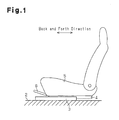
Fig. 1 is a side view which shows a seat sliding device and a seat for a vehicle in the present invention. -
Fig. 2 is an exploded perspective view which shows the seat sliding device inFig. 1 . -
Fig. 3(a) is a longitudinal sectional view which shows the same embodiment. -
Fig. 3(b) is a longitudinal sectional view which shows the same embodiment. -
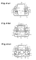
Fig. 4(a) is a sectional view along the line A-A inFig. 3(a) . -
Fig. 4(b) is a sectional view respectively along the line B-B inFig. 3(a) . -
Fig. 4(c) is a sectional view respectively along the line C-C inFig. 3(a) . -
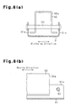
Fig. 5(a) is a plan view which shows a wire spring. -
Fig. 5(b) is a side view which shows a wire spring. -
Fig. 6 is a sectional view which shows an assembly state of the same embodiment. -
Fig. 7 is a perspective view which shows a latch member. -
Fig. 8(a) is a transverse sectional view which shows a conventional mode schematically. -
Fig. 8(b) is a longitudinal sectional view which shows a conventional mode schematically. - A description will be given of one embodiment of the present invention with reference to
Fig. 1 to Fig. 7 . As shown inFig. 1 , alower rail 3 as a first rail is fixed on a vehicle floor 2 in such a manner to extend in the back and forth direction of a vehicle. Anupper rail 4 as a second rail is attached to thelower rail 3 to make relative movement with respect to thelower rail 3 in the back and forth direction. - A pair of the
lower rail 3 and theupper rail 4 shown inFig. 1 is one of two pairs placed in the widthwise direction of the vehicle (a direction orthogonal to the space inFig. 1 ), with an interval therebetween. In this case, there is shown the pair arranged on the left side with respect to the front. Aseat 5 on which a passenger sits is fixed and supported on the upper rails 4. Normally, relative movement of theupper rail 4 with respect to thelower rail 3 is kept restricted in principle. There is arranged arelease handle 6 which releases the restricted state. - As shown in
Fig. 2 , thelower rail 3 is provided with a pair of firstside wall parts 11, which are composed of plate members and vertically extend to both sides in the widthwise direction and a firstcoupling wall part 12, which couples the base ends of the firstside wall parts 11, that is, both lower ends. A first foldedwall part 13 which extends internally in the widthwise direction and is folded toward the base end of each of the firstside wall parts 11 is formed at a distal end of each of the firstside wall parts 11, that is, at an upper end thereof, to continue to the firstside wall part 11. - The
upper rail 4 is provided with second side wall parts 14 (first supporting parts) as a pair of side wall parts which are composed of plate members and vertically extend between the first foldedwall parts 13 of thelower rail 3 and a second coupling wall part 15 (coupling part) as a coupling wall part that couples the base ends of the secondside wall parts 14 in which the base ends of the secondside wall parts 14 are spaced away from thelower rail 3, that is, both upper ends thereof, as shown together inFig. 4(a) to Fig. 4(c) . Then, a second foldedwall part 16 which extends outward in the widthwise direction and is folded to be enclosed by the firstside wall part 11, and the first foldedwall part 13 is formed at a distal end of each of the secondside wall parts 14, that is, at a lower end thereof, in such a manner to continue to the secondside wall part 14. - That is, each of the
lower rail 3 and theupper rail 4 is provided with a substantially U-shaped cross section, and these rails are butted together so that their opening parts face each other. The rails are prevented from being detached in the vertical direction mainly by engagement between the first foldedwall parts 13 and the second foldedwall parts 16. Thelower rail 3 and theupper rail 4 configure a rail cross section which assumes substantially a rectangular box shape. Thelower rail 3 configures an inner space S together with theupper rail 4. - As shown in
Fig. 3(a) andFig. 4(c) , a pair of rollingmembers 20 are attached in the back and forth direction between each of the second foldedwall parts 16 and each of the firstside wall parts 11 which faces thereto. Theupper rail 4 is supported to be slidable with respect to thelower rail 3 in the longitudinal direction (in the back and forth direction) in such a manner that the rollingmembers 20 are rolled between theupper rail 4 and thelower rail 3. - As shown in
Fig. 3(a) and Fig. 3(b) , a plurality ofnotches 13a extending upward from the distal end of thelower rail 3, that is, from the lower end thereof, are formed at an intermediate part of each of the first foldedwall parts 13 of thelower rail 3 in the longitudinal direction, with a predetermined interval kept therebetween in the longitudinal direction. Rectangular tooth-like lock pawls 13b are individually formed betweenadjacent notches 13a. Thus, the plurality oflock pawls 13b are arranged in parallel in the longitudinal direction of thelower rail 3, with the above-described predetermined interval kept therebetween. Also, arestriction part 17 extending further downward in a stepwise manner from the distal end of the first foldedwall part 13, that is, from the lower end thereof, is formed at each end of the first foldedwall parts 13 of thelower rail 3 in the longitudinal direction. As a matter of course, all the plurality oflock pawls 13b are arranged to be held between therestriction parts 17 of the lower rail 3 (first folded wall parts 13) in the longitudinal direction. - Two side wall
part attachment holes 14a are formed at an intermediate part of each of the secondside wall parts 14 of theupper rail 4 in the longitudinal direction, with an interval therebetween in this direction. Further, as also shown inFig. 4(a) , a folded wallpart attachment hole 16a is formed at each of the second foldedwall parts 16 of theupper rail 4 to face each of the side wallpart attachment holes 14a in the widthwise direction. The side wallpart attachment hole 14a and the folded wallpart attachment hole 16a are arranged in the vertical direction between the lower end of the first folded wall part 13 (lockpawl 13b) and the lower end of therestriction part 17. - A
latch member 40 is inserted into the side wallpart attachment hole 14a and the folded wallpart attachment hole 16a adjacent to each other in the widthwise direction in a manner to bridge the secondside wall part 14 and the second foldedwall part 16 in the widthwise direction. As shown inFig. 7 , thelatch member 40 is made of, for example, a blade spring prepared by folding a metal plate member into a U-shape. Thelatch member 40 is integrally provided with a pair ofengagement pieces 41 which spread substantially parallel to each other and a substantiallysemi-cylindrical coupling part 42 for connecting theengagement pieces 41. At the center part of eachengagement piece 41, there is formed a retainingpart 43 which is cut and extended outward to be spaced away from each other, with the vicinity of thecoupling part 42 given as a base end. In a state that thelatch member 40 is able to move, a vertical distance between theend parts 41 a of theengagement pieces 41 is set slightly larger than a vertical distance between both inner wall surfaces of the side wallpart attachment holes 14a. - When the
latch member 40 is assembled to theupper rail 4, thelower rail 3 and theupper rail 4 are assembled in advance so that the side wallpart attachment hole 14a and the folded wallpart attachment hole 16a are arranged between therestriction parts 17 in the longitudinal direction. As shown inFig. 6 , in this state, thelatch member 40 is sequentially inserted into the side wallpart attachment hole 14a and the folded wallpart attachment hole 16a from inside theupper rail 4 outward in the widthwise direction. That is, thelatch member 40 is sequentially inserted into the side wallpart attachment hole 14a and the folded wallpart attachment hole 16a, with thecoupling part 42 kept ahead. At this time, theengagement pieces 41 or the retainingparts 43 are pressed to inner wall surface parts facing each other in the vertical direction which are inner wall surfaces of the side wallpart attachment hole 14a, by which thelatch member 40 undergoes elastic deformation so that theengagement pieces 41 are closed in this direction. Then, thecoupling part 42 penetrates through the folded wallpart attachment hole 16a and also the retainingparts 43 pass through the side wallpart attachment hole 14a. Therefore, the retainingparts 43 are released from both vertical inner wall surfaces of the side wallpart attachment hole 14a, by which thelatch member 40 resumes elasticity to open theengagement pieces 41 in the vertical direction. At this time, each of the retainingparts 43 engages with an edge part of the side wallpart attachment hole 14a in a direction reverse to an insertion direction into the side wallpart attachment hole 14a (that is, inward in the widthwise direction), thereby thelatch member 40 is suppressed from being detached from theupper rail 4. Accordingly,end parts 41a of theengagement pieces 41 are pressure-contacted to the vertical inner wall surfaces of the side wallpart attachment hole 14a, by which thelatch member 40 is retained on theupper rail 4. - Here, as a matter of course, the
latch member 40 bridges the secondside wall part 14 and the second foldedwall part 16 in the widthwise direction opens a movement trajectory of the first foldedwall part 13, and cuts across a movement trajectory of therestriction part 17 in a direction in which thelower rail 3 and theupper rail 4 make relative movement. Therefore, when thelower rail 3 and theupper rail 4 make relative movement, thecorresponding restriction part 17 and thelatch member 40 are brought into contact to restrict the movement. At this time, as shown inFig. 3(a) , thelatch member 40 is in contact with therestriction part 17 on anend surface 41 b in the back and forth direction thereof, that is, in a direction orthogonal to the vertical direction that is the thickness direction of theengagement pieces 41. Thereby, a distance of relative movement between thelower rail 3 and theupper rail 4 is restricted within a predetermined range. - As shown in
Fig. 2 , a circularshaft attachment hole 16b which is located further forward than the folded wallpart attachment hole 16a on the front side is formed at each of the second foldedwall parts 16 of theupper rail 4. A fan-shaped throughhole 16c centering on theshaft attachment hole 16b in an intermediate part between the folded wallpart attachment holes 16a is also formed at each of the second foldedwall parts 16. A pair of slit-like supportingholes 21 which are arranged in the widthwise direction in parallel further forward than theshaft attachment hole 16b are formed on the secondcoupling wall part 15 of theupper rail 4. Both supportingholes 21 extend in the back and forth direction. - Further, as shown in
Fig. 3(a) , a circular shaft attachment hole 14b which is concentric with theshaft attachment hole 16b is formed at each of the secondside wall parts 14 of theupper rail 4. Still further, a fan-shaped throughhole 14c centering on the shaft attachment hole 14b in an intermediate part between the side wallpart attachment holes 14a is formed at each of the secondside wall parts 14. The shaft attachment holes 14b, 16b are mutually equal in inner diameter, and the throughholes Fig. 4(b) , mutually similar in opening shape and face in the widthwise direction. - As shown in
Fig. 3(a) , alock lever 30 is coupled inside theupper rail 4 by acylindrical support pin 22, which is a rotating shaft with a center line (axis) extending in the widthwise direction to rotate. That is, as shown inFig. 2 , thelock lever 30 is provided with ahandgrip part 31 composed of a plate member extending in the back and forth direction. Thehandgrip part 31 is extended in such a manner that two vertical wall parts 32 (second supporting parts) are arranged in parallel in the widthwise direction all over the length thereof in the longitudinal direction. A distance between thevertical wall parts 32 in the widthwise direction is set smaller than a distance between the secondside wall parts 14 of theupper rail 4 in the widthwise direction. Then, each of thevertical wall parts 32 is such that an upper end edge space is connected in the widthwise direction by aretention wall 33 at each of the front end parts and the upper end edge space is also connected in the widthwise direction by atop plate part 34 at each of the rear end parts. Then, a circularshaft attachment hole 35 which is concentric with the support pin 22 (shaft attachment holes 14b, 16b) is formed at each of thevertical wall parts 32. The support pins 22, the ends of which are inserted into the shaft attachment holes 14b, 16b, are inserted into and supported by the shaft attachment holes 35, by which thehandgrip part 31 is coupled to theupper rail 4 to rotate. - It is noted that the
retention wall 33 assumes a circular-arc shape which is raised downward when viewed laterally. Further, each of thevertical wall parts 32 is provided with a flange-shaped supportingwall 32a which protrudes internally in the widthwise direction and facing each other from a lower end edge between theretention wall 33 and theshaft attachment hole 35 in the back and forth direction. - A pair of joining
parts 36 protrude at each of thevertical wall parts 32 downward from a lower end of the rear end part thereof which is below thetop plate part 34, with an interval kept therebetween in the back and forth direction. Each of the joiningparts 36 is configured so that a pair of joiningpieces 36a, 36b arranged to be adjacent in the back and forth direction are given as one set. On the other hand, thelock lever 30 is provided with a flat-plate likelock plate 37 which spreads in the back and forth direction and in the widthwise direction in such a manner to penetrate through the throughholes holes 38 which open in the vertical direction to face the respective joiningparts 36 are formed on thelock plate 37. Thelock plate 37 is joined and fixed to thehandgrip part 31 by crimping the distal ends of the joiningpieces 36a, 36b which penetrate through the joininghole 38, for example, to open in the back and forth direction after insertion of the joiningpart 36 into each of the joining holes 38. - Further, a plurality of lock holes 39 (three holes) which are arranged in parallel in the back and forth direction outward from the joining
part 36 in the widthwise direction are formed on thelock plate 37, with the predetermined interval therebetween. As also shown inFig. 4(b) , each of the lock holes 39 is opened in the vertical direction to face the first foldedwall part 13 and arranged at a position that can be in alignment with each of a plurality oflock pawls 13b (three pawls) adjacent in the longitudinal direction of thelower rail 3. - Then, as shown by the solid line in
Fig. 4(b) , when thelock lever 30 rotationally moves about thesupport pin 22 so that thelock plate 37 ascends, each of the lock holes 39 is able to accept acorresponding lock pawl 13b. When each of the lock holes 39 accepts thecorresponding lock pawl 13b, restrictions are placed on relative movement between thelower rail 3 and theupper rail 4. On the other hand, as shown by the chain double-dashed line inFig. 4(b) , when thelock lever 30 rotationally moves about thesupport pin 22 so that thelock plate 37 descends, each of the lock holes 39 is detached from thecorresponding lock pawl 13b. At this time, restrictions on relative movement between thelower rail 3 and theupper rail 4 are released. - As shown in
Fig. 2 , awire spring 50 composed of one linear element as an urging member is arranged inside theupper rail 4. As shown inFig. 5(a) , thewire spring 50 is substantially U-shaped and opened backward in a planar view. Thewire spring 50 is provided with a pair ofextension parts 51 which are symmetrical and extend in the back and forth direction and aconnection part 52 which connects the front ends of theextension parts 51 in the widthwise direction. Further, as shown inFig. 5(b) , each of theextension parts 51 is provided with a fixing part 53 (latch part) at which an intermediate part in the longitudinal direction is curved out upward and also provided with acoil part 54 which is wound clockwise backward at the rear side of the fixingpart 53. Then, thewire spring 50 configures a first urgingpart 55 at a site further backward than the fixingpart 53 of each of theextension parts 51 including thecoil part 54 and also forms a second urgingpart 56 at a site further forward than theconnection part 52 and the fixingpart 53 of each of theextension parts 51. - As shown in
Fig. 3(a) , thewire spring 50 is arranged substantially inside thehandgrip part 31 in such a manner that each of the fixingparts 53 is allowed to protrude from a corresponding supportinghole 21 of theupper rail 4. Further, thecoil part 54 is wound about thesupport pin 22, by which thewire spring 50 is supported by the upper rail 4 (the second side wall parts 14). Thewire spring 50 is such that each of the fixingparts 53 is brought into contact with the rear end surface of the supportinghole 21, and the rear end part of the first urgingpart 55 is elastically brought into contact with the lower surface of thelock plate 37 further backward than the coil part 54 (support pin 22). That is, the first urgingpart 55 is subjected to bending deformation including thecoil part 54, with a position which fixes the upper rail 4 (fixing part 53) given as a supporting point, and urging thelock lever 30 by using the fixing position as the supporting point. Therefore, thelock lever 30 is urged by the wire spring 50 (first urging part 55) to rotationally move in a direction in which thelock plate 37 ascends, that is, in a direction in which alock pawl 13b corresponding to eachlock hole 39 is fitted. The upper surface of the handgrip part 31 (top plate part 34) is brought into contact with the lower surface of the secondcoupling wall part 15, thereby placing restrictions on a rotational movement of thelock plate 37. - The
coil part 54 is placed at the first urgingpart 55. This is because an elastic coefficient (spring constant) on bending deformation is practically reduced, while the extension length of the first urgingpart 55 is suppressed in the back and forth direction. The fixingparts 53 of thewire spring 50 are kept out of contact with the front end surface of the supportinghole 21. Then, theconnection part 52 of the wire spring 50 (second urging part 56) is arranged further forward than theretention wall 33. - The release handle 6 is made by bending a tubular member and formed to bridge the
upper rails 4 at the front side thereof in the widthwise direction. As shown inFig. 2 , adistal end part 61 extending at the back of therelease handle 6 assumes a cylindrical shape, the outer diameter of which is smaller than a distance between thevertical wall parts 32 in the widthwise direction. And, a slit-like supportinggroove 62 extending in the widthwise direction is formed at the lower part of thedistal end part 61. - As shown in
Fig. 3(a) , therelease handle 6 is inserted below theretention wall 33 of the handgrip part 31 (lock lever 30) to which each of thedistal end parts 61 corresponds and above the supportingwalls 32a, that is, between thevertical wall parts 32. Then, thedistal end part 61 is latched and retained by theconnection part 52 of the wire spring 50 (the second urging part 56) which is fitted into the supportinggroove 62. That is, therear end surface 62a of the supportinggroove 62 is given as an engagement surface with theconnection part 52 for suppressing detachment of thedistal end part 61 of therelease handle 6. Further, thedistal end part 61 inserted between thevertical wall parts 32 is arranged to face thesupport pin 22 on a backward extension line thereof. Thereby, even where thedistal end part 61 is excessively inserted between thevertical wall parts 32, it is restricted to a predetermined range until thedistal end part 61 is in contact with thesupport pin 22. - Then, the
distal end part 61 inserted between thevertical wall parts 32 is urged on the supportinggroove 62 by the wire spring 50 (second urging part 56) to ascend. Thereby, thedistal end part 61 is retained to make an integral rotation with thelock lever 30 substantially about thesupport pin 22 in such a manner that upper and lower parts of thedistal end part 61 are respectively brought into contact with a lower surface of theretention wall 33 and upper surfaces of the supportingwalls 32a. That is, thewire spring 50 is also provided with functions to keep the release handle 6 elastically so that therelease handle 6 makes an integral rotation with thelock lever 30. The distal end part 61 (release handle 6) is elastically retained at theconnection part 52 of thewire spring 50. This is because, for example, thelock lever 30 is coupled, with an appropriate clearance kept. Alternatively, this is because when the distal end part 61 (release handle 6) tries to make rotational movement about thesupport pin 22 in a direction reverse to an original operating direction due to an unintended external force, etc., thedistal end part 61 is allowed to sway with respect to thelock lever 30, thereby avoiding an excessively large load on thelock lever 30. Further, theconnection part 52 of the wire spring 50 (second urging part 56) which latches thedistal end part 61 of therelease handle 6 is arranged further forward than theretention wall 33. This is because therelease handle 6 is suppressed from swaying about theconnection part 52 with respect to thelock lever 30. - Next, a description will be given of actions of the present embodiment.
- First, the
release handle 6 is assumed to be released from an operating force thereof. At this time, thewire spring 50 generates in association with bending deformation an urging force which urges thelock lever 30 in the vertical direction toward a direction in which thelock lever 30 engages with thelower rail 3. Thelock lever 30 is allowed to rotationally move by an urging force of the wire spring 50 (the first urging part 55) in a direction in which thelock plate 37 ascends about thesupport pin 22 integrally with the distal end part 61 (release handle 6), that is, in a direction in which acorresponding lock pawl 13b is fitted into each of the lock holes 39. Thereby, restrictions are placed on relative movement between thelower rail 3 and theupper rail 4 in the above-described manner. Then, there is retained a position of theseat 5 which is supported by theupper rail 4 in the back and forth direction. - Here, the
release handle 6 is assumed to be operated to raise a front end thereof. At this time, against the urging force of the wire spring 50 (the first urging part 55), thelock lever 30 is allowed to rotationally move integrally with the distal end part 61 (release handle 6) in a direction in which thelock plate 37 descends about thesupport pin 22, that is, to a side where each of the lock holes 39 is detached from acorresponding lock pawl 13b. Thereby, restrictions on relative movement between thelower rail 3 and theupper rail 4 are released in the above-described manner. Then, it is possible to adjust a position of theseat 5 supported by theupper rail 4 in the back and forth direction. As described so far, the wire spring 50 (the first urging part 55) is decreased in spring constant on bending deformation only by length of thecoil part 54. Therefore, therelease handle 6 is also decreased in operating force required for release operation at this time. In particular, when theupper rail 4 moves to the most forward position or the most backward position with respect to the correspondinglower rail 3, therestriction part 17 is brought into contact with thelatch member 40 in the above-described manner, thereby restricting the movement. Accordingly, a distance of relative movement between thelower rail 3 and theupper rail 4 is restricted within a predetermined range. At this time, thelatch member 40 is brought into contact with therestriction part 17 in a state of being supported by theupper rail 4 on both sides, thereby more securely restricting the movement. Specifically, thelatch member 40 is supported on both sides by the secondside wall parts 14 and the second foldedwall parts 16 which are adjacent in the widthwise direction of theupper rail 4. - As so far described in detail, the present embodiment is able to provide the following effects.
- (1) The
lock lever 30 is urged in a vertical direction, that is, in a direction in which thelock lever 30 engages with thelower rail 3 by an urging force in association with bending deformation of the wire spring 50 (the first urging part 55). In this case, the effective length of thewire spring 50 in relation to a spring constant on bending deformation is determined by a length between a position latched to the second coupling wall part 15 (the fixingpart 53, that is, the latch part) and thesupport pin 22 at theextension parts 51, a length between a position latched to the lock lever 30 (latch end part) and thesupport pin 22, and a length of thecoil part 54. Therefore, a spring constant of thewire spring 50 on bending deformation can be decreased only by the length of thecoil part 54. Thereby, it is possible to decrease the spring constant of thewire spring 50 on bending deformation without unnecessarily extending an end part of the wire spring 50 (the first urging part 55) from thesupport pin 22 to the secondcoupling wall part 15. Then, it is possible to suppress an increase in operating force required for disengaging thelock lever 30 from thelower rail 3, with restrictions on an arrangement space being decreased.
Further, thewire spring 50 is supported substantially by theupper rail 4 at two points, that is, at one end part which is latched to the second coupling wall part 15 (supporting hole 21) and at thesupport pin 22 which is wound about thecoil part 54 at each of theextension parts 51. Therefore, thewire spring 50 can be made more stable in posture. - (2) Since the release handle 6 (distal end part 61) is retained to be elastically connected with respect to the
lock lever 30 at the second urgingpart 56 of thewire spring 50, it can be connected, for example, with respect to the lock lever in appropriate moderation. Further, the second urgingpart 56 is arranged integrally with thewire spring 50. It is, therefore, possible to suppress an increase in the number of components, with the above-described functions added. - (3) The
second urging part 56 is not in contact with the end surfaces (front end surfaces) of the supportingholes 21 of theupper rail 4 in the longitudinal direction. Therefore, the effective length of the second urgingpart 56 with regard to a spring constant on bending deformation is made longer, for example, than a case where the second urgingpart 56 is brought into contact with the end surfaces (front end surfaces) of the supportingholes 21 of theupper rail 4 in the longitudinal direction. It is, thus, possible to decrease the spring constant of the second urgingpart 56 on bending deformation. - (4) The
support pin 22 faces on an extension line in a direction in which thelock lever 30 is inserted between thevertical wall parts 32. Thereby, even if thelock lever 30 is excessively inserted, the release handle 6 (distal end part 61) is able to be restricted in the insertion to a predetermined range until therelease handle 6 is in contact with thesupport pin 22. - (5) The
wire spring 50 can be formed by simply bending a single linear element. - (6) On relative movement between the
lower rail 3 and theupper rail 4, therestriction part 17 and thelatch member 40 are in contact with each other to restrict the relative movement. Thereby, a distance of relative movement between thelower rail 3 and theupper rail 4 is restricted within a predetermined range. When thelatch member 40 is in contact with therestriction part 17, thelatch member 40 supports therestriction part 17 in such a state to support the upper rail 4 (the secondside wall parts 14 and the second folded wall parts 16) on both sides. Therefore, it is possible to more securely restrict the relative movement between thelower rail 3 and theupper rail 4. In particular, thelatch member 40 can be arranged at any given position of theupper rail 4 in the longitudinal direction, as long as interference with peripheral components (such as the lock lever 30) can be avoided. It is, therefore, possible to increase the degree of freedom in terms of adjusting a range of restricting the distance of relative movement between thelower rail 3 and theupper rail 4. - (7) When assembled from inside to the
upper rail 4, thelatch member 40 can be easily assembled to theupper rail 4 by procedures in which thelatch member 40 is inserted into the side wallpart attachment hole 14a and the folded wallpart attachment hole 16a, with elastic deformation carried out so that theend parts 41 a are closed in the vertical direction, and theend parts 41a are pressure-contacted to the inner wall surfaces which face each other in the vertical direction of the side wallpart attachment hole 14a. - (8) When the
restriction part 17 and thelatch member 40 are in contact with each other, thelatch member 40 supports therestriction part 17 on theend surface 41 b in a direction orthogonal to the thickness direction. Therefore, thelatch member 40 is able to more securely restrict relative movement between thelower rail 3 and theupper rail 4 than a case where, for example, therestriction part 17 is supported in the thickness direction. - (9) The retaining
part 43 engages with an edge part of the side wallpart attachment hole 14a in a direction reverse to an insertion direction into the side wallpart attachment hole 14a and the folded wallpart attachment hole 16a. Thereby, thelatch member 40 can be suppressed from being detached from theupper rail 4. - (10) There is eliminated a necessity for work of bending the
upper rail 4 which is required in a conventional stopper structure in a step after assembly of thelower rail 3 and theupper rail 4. - It is noted that the above-described embodiment may be modified as follows.
- It is acceptable that the wire spring 50 (the first and second urging
parts 55, 56) is configured only with asingle extension part 51. - It is acceptable that the
wire spring 50 is formed with a linear element having a circular cross section or formed with a linear element having a rectangular cross section (what is called a band material). - It is acceptable that an urging member which urges the
lock lever 30 and a member which retains the release handle 6 (the distal end part 61) are provided separately. - It is acceptable that the
support pin 22 is supported by the lock lever 30 (the vertical wall parts 32), with the end parts thereof fixed to the upper rail 4 (the second side wall parts 14), or fixed to the lock lever 30 (the vertical wall parts 32), with the end parts thereof pivotally supported by the upper rail 4 (the second side wall parts 14). - It is acceptable that the
lower rail 3 or theupper rail 4 is configured by a plurality of plate members that are connected by welding, etc. - It is acceptable that a relationship in which the
lower rail 3 is fixed to theupper rail 4 and a relationship in which the vehicle floor 2 is fixed to the seat 5 (in other words, a vertical arrangement relationship) are reversed. In this case, it is acceptable that the release operation of thelock lever 30 arranged on the vehicle floor 2 side may be performed by using any suitable operating member such as a cable. - It is acceptable that the
lower rail 3 and the upper rail 4 (seat sliding device for a vehicle) are in such a configuration that one each is placed or three or more each are placed with respect to theseat 5. - It is acceptable that in association with relative movement between the lower rail and the upper rail, the seat moves in the widthwise direction of the seat, for example.
- It is acceptable that a retaining part of the
latch member 40 is such that it engages with an edge part of the folded wallpart attachment hole 16a, thereby suppressing detachment from theupper rail 4. - It is acceptable that the
latch member 40 is assembled to theupper rail 4 to support therestriction part 17 on an end surface in the thickness direction. - It is acceptable that the
latch member 40 to be arranged on theupper rail 4 is provided solely on one side of theupper rail 4 in the widthwise direction. - It is acceptable that the
restriction part 17 and thelatch member 40 are placed only on one side of each of thelower rail 3 and theupper rail 4 in the widthwise direction. - It is acceptable that the
restriction part 17 is arranged at an intermediate part of the lower rail 3 (the first folded wall part 13) in the longitudinal direction and also thelatch member 40 is arranged at both end parts of theupper rail 4 in the longitudinal direction. In this case, it is acceptable that therestriction part 17 arranged on one side of thelower rail 3 in the widthwise direction is provided solely or in a pair arranged in the longitudinal direction, with an interval kept therebetween. - It is acceptable that the latch member is a flat and plate-like or a wedge-like latch member in which both end parts thereof are press-fitted or welded into the side wall
part attachment hole 14a and the folded wallpart attachment hole 16a mutually adjacent in the widthwise direction and bridging the secondside wall part 14 and the second foldedwall part 16. - 2 ... vehicle floor, 3 ... lower rail (first rail), 4 ... upper rail (second rail), 5 ... sheet, 6 ... release handle (operating member), 11 ... first side wall part, 13 ... first folded wall part, 14 ... second side wall part (side wall part, first supporting part), 14a ... side wall part attachment hole, 15 ... second coupling wall part (coupling wall part, coupling part), 16 ... second folded wall part, 16a ... folded wall part attachment hole, 17 ... restriction part, 21 ... supporting hole, 22 ... support pin (rotating shaft), 30 ... lock lever, 31 ... handgrip part, 32 ... vertical wall part (second supporting part), 37 ... lock plate, 40 ... latch member, 41 ... engagement piece, 41 a ... end part, 41 b ... end surface, 42 ... coupling part, 43 ... retaining part, 50 ... wire spring (urging member), 54 ... coil part, 55 ... first urging part, 56 ... second urging part (urging part)
Claims (10)
- A seat sliding device for a vehicle comprising:a first rail, which is adapted to be fixed to one of a vehicle floor and a seat;a second rail, which is adapted to be fixed to the other one of the vehicle floor and the seat and coupled to the first rail to make a relative movement with respect to the first rail, wherein the second rail has a pair of side wall parts arranged in a widthwise direction in parallel and a coupling wall part, which couples base ends of the side wall parts in which the base ends of the side wall parts are spaced away from the first rail;a rotating shaft, which has an axis extending in the widthwise direction and which bridges the side wall parts;a lock lever, which has a pair of vertical wall parts that are arranged in parallel between the side wall parts in the widthwise direction and through which the rotating shaft penetrates, wherein the lock lever rotationally moves about the axis in one direction to engage with the first rail, thereby restricting relative movement between the first rail and the second rail and rotationally moves about the axis in the other direction to release the engagement with the first rail, thereby releasing restrictions on the relative movement; andan urging member, which has a latch part latched to the coupling wall part and a latch end part latched to the lock lever, wherein the urging member generates in association with bending deformation an urging force that urges the lock lever in a vertical direction in which the lock lever engages with the first rail, whereinthe urging member has a coil part, which is wound about the rotating shaft between the latch part and the latch end part.
- The seat sliding device for a vehicle according to claim 1, further comprising an operating member which is connected to the lock lever to transmit an operating force for releasing restrictions on the relative movement to the lock lever, wherein
the urging member is integrally provided with an urging part which is extended from the latch part and latched to the operating member, thereby elastically retaining a state that the operating member is connected with respect to the lock lever. - The seat sliding device for a vehicle according to claim 2, wherein
the latch part of the urging member is inserted into a supporting hole formed at the coupling wall part and latched to the coupling wall part in a state of being in contact with one end surface of the supporting hole of the second rail in the longitudinal direction, and
the urging part is not in contact with any given end surface of the supporting hole of the second rail in the longitudinal direction. - The seat sliding device for a vehicle according to claim 2 or 3, wherein
the operating member is inserted between the vertical wall parts, and
the operating member faces the rotating shaft on an extension line in a direction in which the operating member is inserted between the vertical wall parts. - The seat sliding device for a vehicle according to any one of claims 1 to 4, wherein
the urging member is a wire spring composed of a single linear element. - A seat sliding device for a vehicle which is arranged on a vehicle having a floor and a seat, comprising:a first rail, which is adapted to be fixed to one of the floor and the seat;a second rail, which is adapted to be fixed to the other one of the floor and the seat and coupled to the first rail to make relative movement with respect to the first rail, wherein the second rail has a pair of first supporting parts arranged in parallel in a widthwise direction of the vehicle and a coupling part, which couples the base ends of the pair of first supporting parts in which the base ends of the pair of first supporting parts are spaced away from the first rail;a rotating shaft, which has an axis extending in the widthwise direction of the vehicle and is supported between the first supporting parts to rotate;a lock lever, which has a pair of second supporting parts that are arranged in parallel between the first supporting parts in the widthwise direction of the vehicle and through which the rotating shaft penetrates; andan urging member, which has a latch part latched to the coupling wall part, a latch end part latched to the lock lever, and a coil part wound about the rotating shaft between the latch part and the latch end part, thereby generating in association with bending deformation an urging force for urging the lock lever in a vertical direction of the vehicle so that the lock lever engages with the first rail, whereinwhen the lock lever rotates about the axis in one direction, the lock lever engages with the first rail to prevent relative movement between the first rail and the second rail, and when the lock lever rotates about the axis in the other direction, the first rail is released from the engagement with the lock lever, thereby allowing the relative movement.
- A seat sliding device for a vehicle which is installed on a vehicle having a floor and a seat, comprising:a first rail, which is adapted to be fixed to one of the floor and the seat; anda second rail, which is adapted to be fixed to the other one of the floor and the seat and coupled to the first rail to make relative movement with respect to the first rail, whereinthe first rail is provided with a pair of first side wall parts arranged in a widthwise direction in parallel, two first folded wall parts, which individually extend inward in the widthwise direction facing each other from distal ends of the first side wall parts and folded toward the base ends of the first side wall parts, and a restriction part further extending from distal end of the first folded wall part at a predetermined position of the first rail in the longitudinal direction, andthe second rail is provided with a pair of second side wall parts arranged in parallel between the first side wall parts in the widthwise direction, two second folded wall parts extending individually outward in the widthwise direction mutually spaced away from distal ends of the second side wall parts and folded to be enclosed with the first side wall parts and the first folded wall parts, and a side wall part attachment hole and a folded wall part attachment hole, which are formed to respectively face in the widthwise direction the second side wall parts and the second folded wall parts are adjacent at a predetermined position of the second rail in the longitudinal direction, andthe seat sliding device for a vehicle is provided with a latch member, which is inserted into the side wall part attachment hole and the folded wall part attachment hole to bridge the second side wall parts and the second folded wall parts in the widthwise direction, opens a movement trajectory of the first folded wall part in a direction in which the first rail and the second rail make relative movement, and cuts across a movement trajectory of the restriction part.
- The seat sliding device for a vehicle according to claim 7, wherein
an inner wall surface of the side wall part attachment hole or that of the folded wall part attachment hole has an inner wall surface part facing in one direction, and
the latch member is a blade spring folded to have both end parts which are pressure-contacted with the inner wall surface part. - The seat sliding device for a vehicle according to claim 7 or 8, wherein
the latch member is composed of a plate member and able to be in contact with the restriction part on an end surface in a direction orthogonal to the thickness direction thereof. - The seat sliding device for a vehicle according to claim 7 or 8, wherein the latch member is provided with a retaining part which is cut and extended to engage with an edge part of the side wall part attachment hole or that of the folded wall part attachment hole in a direction reverse to an insertion direction into the side wall part attachment hole and the folded wall part attachment hole.
Applications Claiming Priority (2)
| Application Number | Priority Date | Filing Date | Title |
|---|---|---|---|
| JP2011154132A JP5621724B2 (en) | 2011-07-12 | 2011-07-12 | Vehicle seat slide device |
| PCT/JP2012/066426 WO2013008629A1 (en) | 2011-07-12 | 2012-06-27 | Seat sliding device for vehicle |
Publications (2)
| Publication Number | Publication Date |
|---|---|
| EP2733014A1 true EP2733014A1 (en) | 2014-05-21 |
| EP2733014A4 EP2733014A4 (en) | 2015-03-04 |
Family
ID=47505926
Family Applications (1)
| Application Number | Title | Priority Date | Filing Date |
|---|---|---|---|
| EP12811993.0A Withdrawn EP2733014A4 (en) | 2011-07-12 | 2012-06-27 | SEAT SLIDING DEVICE FOR VEHICLE |
Country Status (5)
| Country | Link |
|---|---|
| US (1) | US9283870B2 (en) |
| EP (1) | EP2733014A4 (en) |
| JP (1) | JP5621724B2 (en) |
| CN (1) | CN203854532U (en) |
| WO (1) | WO2013008629A1 (en) |
Cited By (3)
| Publication number | Priority date | Publication date | Assignee | Title |
|---|---|---|---|---|
| FR3033742A1 (en) * | 2015-03-20 | 2016-09-23 | Faurecia Sieges Automobile | SLIDE FOR VEHICLE SEAT AND VEHICLE SEAT COMPRISING SUCH A SLIDER |
| WO2017021383A1 (en) * | 2015-08-06 | 2017-02-09 | Johnson Controls Gmbh | Longitudinal adjusting device for a vehicle seat |
| DE102020200836B4 (en) | 2019-01-25 | 2022-11-10 | Tachi-S Co., Ltd. | SLIDING DEVICE |
Families Citing this family (28)
| Publication number | Priority date | Publication date | Assignee | Title |
|---|---|---|---|---|
| JP5734890B2 (en) * | 2012-02-15 | 2015-06-17 | シロキ工業株式会社 | Slide rail device for vehicle |
| CN103874603B (en) * | 2012-10-10 | 2016-04-13 | 丰田车体精工株式会社 | Lockout mechanism in seat rail sliding device |
| FR2999123B1 (en) | 2012-12-10 | 2016-12-30 | Faurecia Sieges Dautomobile | SLIDE FOR VEHICLE SEAT AND VEHICLE SEAT COMPRISING SUCH A SLIDER. |
| JP6089759B2 (en) * | 2013-02-19 | 2017-03-08 | アイシン精機株式会社 | Vehicle seat slide device |
| CN109038180A (en) * | 2013-05-15 | 2018-12-18 | 李光伟 | A kind of clamp rotating mechanism |
| JP6253936B2 (en) * | 2013-09-30 | 2017-12-27 | トヨタ紡織株式会社 | Vehicle seat |
| EP3061645B1 (en) * | 2013-10-25 | 2019-09-11 | Aisin Seiki Kabushiki Kaisha | Vehicular seat slide device |
| CN104015634B (en) * | 2014-06-11 | 2016-05-25 | 上海延锋江森座椅有限公司 | A kind of seat slide assembly |
| CN104477056A (en) * | 2015-01-07 | 2015-04-01 | 芜湖南大汽车工业有限公司 | Automobile seat |
| JP6549975B2 (en) * | 2015-02-02 | 2019-07-24 | 株式会社Tf−Metal | Seat slide device |
| JP2016145024A (en) * | 2015-02-02 | 2016-08-12 | 富士機工株式会社 | Seat slide device |
| WO2017021427A1 (en) * | 2015-08-03 | 2017-02-09 | Johnson Controls Gmbh | Stop for a rail of a longitudinally adjustable seat |
| CN105416105B (en) * | 2015-12-17 | 2017-09-01 | 延锋安道拓座椅机械部件有限公司 | Sliding rail of automobile seat unlocking prevention device |
| DE102017208725A1 (en) * | 2016-05-26 | 2017-11-30 | Toyota Boshoku Kabushiki Kaisha | Sitzlängsverstellvorrichtung |
| DE102016225818B4 (en) * | 2016-09-21 | 2021-05-12 | Adient Luxembourg Holding S.À R.L. | Longitudinal adjuster and vehicle seat |
| BR102017006962A2 (en) * | 2017-04-05 | 2018-10-30 | Aethra Sistemas Automotivos S/A | longitudinal movement and adjustment device of motor vehicle seats |
| CN107415781B (en) * | 2017-07-27 | 2019-04-12 | 延锋安道拓座椅有限公司 | A kind of easy access mechanism for automotive seat |
| EP3546281B1 (en) * | 2018-03-16 | 2021-08-25 | TF-Metal Co., Ltd. | Seat slide device |
| IT201800005731A1 (en) | 2018-05-25 | 2019-11-25 | Slider for a vehicle seat | |
| EP3814170B1 (en) * | 2018-06-29 | 2022-04-27 | KEIPER Seating Mechanisms Co., Ltd. | Longitudinal adjuster and vehicle seat |
| CA3123867A1 (en) * | 2018-12-17 | 2020-06-25 | Magna Seating Inc. | Loop latch release for power long rail assembly |
| JP7186102B2 (en) * | 2019-01-25 | 2022-12-08 | トヨタ紡織株式会社 | slide device |
| JP7173884B2 (en) | 2019-01-25 | 2022-11-16 | トヨタ紡織株式会社 | slide device |
| JP7487127B2 (en) * | 2021-02-19 | 2024-05-20 | トヨタ紡織株式会社 | Seat slide device and method for assembling lock spring used in seat slide device |
| JP7765303B2 (en) | 2022-02-15 | 2025-11-06 | 株式会社Tf-Metal | Seat slide device |
| JP7734096B2 (en) | 2022-02-15 | 2025-09-04 | 株式会社Tf-Metal | Seat slide device |
| JP7813684B2 (en) * | 2022-09-22 | 2026-02-13 | 株式会社Tf-Metal | Seat slide device |
| KR102847537B1 (en) | 2023-05-19 | 2025-08-20 | 주식회사 다스 | Installation structure for track lever of seat rail |
Family Cites Families (12)
| Publication number | Priority date | Publication date | Assignee | Title |
|---|---|---|---|---|
| JPS5819836A (en) | 1981-07-30 | 1983-02-05 | 松下電器産業株式会社 | Breaker packaging equipment |
| JPS5819836U (en) | 1981-07-31 | 1983-02-07 | 市光工業株式会社 | Seat adjuster slide amount regulating device |
| JP2830519B2 (en) | 1990-11-16 | 1998-12-02 | 株式会社ニコン | Solid-state imaging device |
| DE69832435T2 (en) * | 1997-05-13 | 2006-08-17 | Delta Kogyo Co. Ltd. | Fahrzeugsitzverstellschienen |
| JP2001187540A (en) * | 1999-12-28 | 2001-07-10 | Delta Kogyo Co Ltd | Seat slide lock structure |
| JP5085900B2 (en) * | 2006-08-15 | 2012-11-28 | シロキ工業株式会社 | Seat track equipment |
| JP2008049891A (en) * | 2006-08-25 | 2008-03-06 | Aisin Seiki Co Ltd | Vehicle seat slide device |
| JP4355963B2 (en) | 2007-01-30 | 2009-11-04 | 株式会社今仙電機製作所 | Slide rail device |
| JP4986036B2 (en) * | 2007-04-05 | 2012-07-25 | トヨタ紡織株式会社 | Vehicle seat slide mechanism |
| JP5239278B2 (en) * | 2007-09-21 | 2013-07-17 | アイシン精機株式会社 | Vehicle seat slide device |
| JP5659974B2 (en) | 2011-07-12 | 2015-01-28 | アイシン精機株式会社 | Vehicle seat slide device |
| JP5962250B2 (en) | 2012-06-21 | 2016-08-03 | アイシン精機株式会社 | Vehicle seat slide device |
-
2011
- 2011-07-12 JP JP2011154132A patent/JP5621724B2/en not_active Expired - Fee Related
-
2012
- 2012-06-27 CN CN201290000627.1U patent/CN203854532U/en not_active Expired - Fee Related
- 2012-06-27 EP EP12811993.0A patent/EP2733014A4/en not_active Withdrawn
- 2012-06-27 WO PCT/JP2012/066426 patent/WO2013008629A1/en not_active Ceased
- 2012-06-27 US US14/131,334 patent/US9283870B2/en not_active Expired - Fee Related
Cited By (3)
| Publication number | Priority date | Publication date | Assignee | Title |
|---|---|---|---|---|
| FR3033742A1 (en) * | 2015-03-20 | 2016-09-23 | Faurecia Sieges Automobile | SLIDE FOR VEHICLE SEAT AND VEHICLE SEAT COMPRISING SUCH A SLIDER |
| WO2017021383A1 (en) * | 2015-08-06 | 2017-02-09 | Johnson Controls Gmbh | Longitudinal adjusting device for a vehicle seat |
| DE102020200836B4 (en) | 2019-01-25 | 2022-11-10 | Tachi-S Co., Ltd. | SLIDING DEVICE |
Also Published As
| Publication number | Publication date |
|---|---|
| CN203854532U (en) | 2014-10-01 |
| US9283870B2 (en) | 2016-03-15 |
| WO2013008629A1 (en) | 2013-01-17 |
| JP5621724B2 (en) | 2014-11-12 |
| EP2733014A4 (en) | 2015-03-04 |
| JP2013018400A (en) | 2013-01-31 |
| US20140138510A1 (en) | 2014-05-22 |
Similar Documents
| Publication | Publication Date | Title |
|---|---|---|
| US9283870B2 (en) | Seat sliding device for vehicle | |
| EP2733013B1 (en) | Seat sliding device for vehicle | |
| JP5830954B2 (en) | Vehicle seat slide device | |
| JP4355963B2 (en) | Slide rail device | |
| JP5845962B2 (en) | Vehicle seat slide device | |
| US8033520B2 (en) | Vehicle seat slide mechanism | |
| JP4947123B2 (en) | Vehicle sliding device | |
| WO2010001956A1 (en) | Seat rail device | |
| JP2009073398A (en) | Vehicle seat slide device | |
| JP5983295B2 (en) | Vehicle seat slide device | |
| JP4234470B2 (en) | Seat slide device | |
| JP5974815B2 (en) | Vehicle seat slide device | |
| JP2014083890A (en) | Sheet slide device for vehicle | |
| JP5505008B2 (en) | Vehicle sliding device | |
| JP5998856B2 (en) | Vehicle seat slide device | |
| JP2010125955A (en) | Slide rail apparatus for vehicle | |
| JP2014100931A (en) | Vehicular seat slide device | |
| JP2010030558A (en) | Vehicular slide rail device | |
| CN101175652B (en) | Sliding car seat | |
| JP5362245B2 (en) | Slide stopper structure for seat track | |
| JP2024137116A (en) | Seat slide device | |
| JP5227284B2 (en) | Slide rail device for vehicle | |
| JP2010173575A (en) | Slide rail device for vehicle | |
| JP2024137109A (en) | Seat slide device | |
| JP2001113996A (en) | Slide device for vehicle seat |
Legal Events
| Date | Code | Title | Description |
|---|---|---|---|
| PUAI | Public reference made under article 153(3) epc to a published international application that has entered the european phase |
Free format text: ORIGINAL CODE: 0009012 |
|
| 17P | Request for examination filed |
Effective date: 20140103 |
|
| AK | Designated contracting states |
Kind code of ref document: A1 Designated state(s): AL AT BE BG CH CY CZ DE DK EE ES FI FR GB GR HR HU IE IS IT LI LT LU LV MC MK MT NL NO PL PT RO RS SE SI SK SM TR |
|
| DAX | Request for extension of the european patent (deleted) | ||
| A4 | Supplementary search report drawn up and despatched |
Effective date: 20150130 |
|
| RIC1 | Information provided on ipc code assigned before grant |
Ipc: B60N 2/08 20060101AFI20150126BHEP Ipc: B60N 2/07 20060101ALI20150126BHEP |
|
| STAA | Information on the status of an ep patent application or granted ep patent |
Free format text: STATUS: EXAMINATION IS IN PROGRESS |
|
| 17Q | First examination report despatched |
Effective date: 20171117 |
|
| STAA | Information on the status of an ep patent application or granted ep patent |
Free format text: STATUS: THE APPLICATION IS DEEMED TO BE WITHDRAWN |
|
| 18D | Application deemed to be withdrawn |
Effective date: 20200603 |