JP5659974B2 - Vehicle seat slide device - Google Patents
Vehicle seat slide device Download PDFInfo
- Publication number
- JP5659974B2 JP5659974B2 JP2011154133A JP2011154133A JP5659974B2 JP 5659974 B2 JP5659974 B2 JP 5659974B2 JP 2011154133 A JP2011154133 A JP 2011154133A JP 2011154133 A JP2011154133 A JP 2011154133A JP 5659974 B2 JP5659974 B2 JP 5659974B2
- Authority
- JP
- Japan
- Prior art keywords
- wall portions
- side wall
- rail
- width direction
- folded
- Prior art date
- Legal status (The legal status is an assumption and is not a legal conclusion. Google has not performed a legal analysis and makes no representation as to the accuracy of the status listed.)
- Expired - Fee Related
Links
Images


Classifications
-
- B—PERFORMING OPERATIONS; TRANSPORTING
- B60—VEHICLES IN GENERAL
- B60N—SEATS SPECIALLY ADAPTED FOR VEHICLES; VEHICLE PASSENGER ACCOMMODATION NOT OTHERWISE PROVIDED FOR
- B60N2/00—Seats specially adapted for vehicles; Arrangement or mounting of seats in vehicles
- B60N2/02—Seats specially adapted for vehicles; Arrangement or mounting of seats in vehicles the seat or part thereof being movable, e.g. adjustable
- B60N2/04—Seats specially adapted for vehicles; Arrangement or mounting of seats in vehicles the seat or part thereof being movable, e.g. adjustable the whole seat being movable
- B60N2/06—Seats specially adapted for vehicles; Arrangement or mounting of seats in vehicles the seat or part thereof being movable, e.g. adjustable the whole seat being movable slidable
- B60N2/07—Slide construction
- B60N2/0702—Slide construction characterised by its cross-section
- B60N2/0705—Slide construction characterised by its cross-section omega-shaped
-
- B—PERFORMING OPERATIONS; TRANSPORTING
- B60—VEHICLES IN GENERAL
- B60N—SEATS SPECIALLY ADAPTED FOR VEHICLES; VEHICLE PASSENGER ACCOMMODATION NOT OTHERWISE PROVIDED FOR
- B60N2/00—Seats specially adapted for vehicles; Arrangement or mounting of seats in vehicles
- B60N2/02—Seats specially adapted for vehicles; Arrangement or mounting of seats in vehicles the seat or part thereof being movable, e.g. adjustable
- B60N2/04—Seats specially adapted for vehicles; Arrangement or mounting of seats in vehicles the seat or part thereof being movable, e.g. adjustable the whole seat being movable
- B60N2/06—Seats specially adapted for vehicles; Arrangement or mounting of seats in vehicles the seat or part thereof being movable, e.g. adjustable the whole seat being movable slidable
- B60N2/07—Slide construction
- B60N2/0702—Slide construction characterised by its cross-section
- B60N2/0715—C or U-shaped
-
- B—PERFORMING OPERATIONS; TRANSPORTING
- B60—VEHICLES IN GENERAL
- B60N—SEATS SPECIALLY ADAPTED FOR VEHICLES; VEHICLE PASSENGER ACCOMMODATION NOT OTHERWISE PROVIDED FOR
- B60N2/00—Seats specially adapted for vehicles; Arrangement or mounting of seats in vehicles
- B60N2/02—Seats specially adapted for vehicles; Arrangement or mounting of seats in vehicles the seat or part thereof being movable, e.g. adjustable
- B60N2/04—Seats specially adapted for vehicles; Arrangement or mounting of seats in vehicles the seat or part thereof being movable, e.g. adjustable the whole seat being movable
- B60N2/06—Seats specially adapted for vehicles; Arrangement or mounting of seats in vehicles the seat or part thereof being movable, e.g. adjustable the whole seat being movable slidable
- B60N2/08—Seats specially adapted for vehicles; Arrangement or mounting of seats in vehicles the seat or part thereof being movable, e.g. adjustable the whole seat being movable slidable characterised by the locking device
- B60N2/0812—Location of the latch
- B60N2/0818—Location of the latch inside the rail
-
- B—PERFORMING OPERATIONS; TRANSPORTING
- B60—VEHICLES IN GENERAL
- B60N—SEATS SPECIALLY ADAPTED FOR VEHICLES; VEHICLE PASSENGER ACCOMMODATION NOT OTHERWISE PROVIDED FOR
- B60N2/00—Seats specially adapted for vehicles; Arrangement or mounting of seats in vehicles
- B60N2/02—Seats specially adapted for vehicles; Arrangement or mounting of seats in vehicles the seat or part thereof being movable, e.g. adjustable
- B60N2/04—Seats specially adapted for vehicles; Arrangement or mounting of seats in vehicles the seat or part thereof being movable, e.g. adjustable the whole seat being movable
- B60N2/06—Seats specially adapted for vehicles; Arrangement or mounting of seats in vehicles the seat or part thereof being movable, e.g. adjustable the whole seat being movable slidable
- B60N2/08—Seats specially adapted for vehicles; Arrangement or mounting of seats in vehicles the seat or part thereof being movable, e.g. adjustable the whole seat being movable slidable characterised by the locking device
- B60N2/0831—Movement of the latch
- B60N2/0837—Movement of the latch pivoting
- B60N2/085—Movement of the latch pivoting about a transversal axis
-
- B—PERFORMING OPERATIONS; TRANSPORTING
- B60—VEHICLES IN GENERAL
- B60N—SEATS SPECIALLY ADAPTED FOR VEHICLES; VEHICLE PASSENGER ACCOMMODATION NOT OTHERWISE PROVIDED FOR
- B60N2/00—Seats specially adapted for vehicles; Arrangement or mounting of seats in vehicles
- B60N2/02—Seats specially adapted for vehicles; Arrangement or mounting of seats in vehicles the seat or part thereof being movable, e.g. adjustable
- B60N2/04—Seats specially adapted for vehicles; Arrangement or mounting of seats in vehicles the seat or part thereof being movable, e.g. adjustable the whole seat being movable
- B60N2/06—Seats specially adapted for vehicles; Arrangement or mounting of seats in vehicles the seat or part thereof being movable, e.g. adjustable the whole seat being movable slidable
- B60N2/08—Seats specially adapted for vehicles; Arrangement or mounting of seats in vehicles the seat or part thereof being movable, e.g. adjustable the whole seat being movable slidable characterised by the locking device
- B60N2/0881—Activation of the latches by the control mechanism
- B60N2/0887—Activation of the latches by the control mechanism with synchronised movements
Description
本発明は、車両フロア及びシートの相対位置を調整するための車両用シートスライド装置に関するものである。 The present invention relates to a vehicle seat slide device for adjusting the relative positions of a vehicle floor and a seat.
従来、こうした車両用シートスライド装置として種々のものが提案されている。例えば特許文献1に記載された車両用シートスライド装置は、上方開口を有する断面略U字状のロアレール(12)と、当該上方開口を塞ぐ断面略U字状のアッパレール(11)とが、長手方向に向けて相互に摺動自在に係合されてなる。そして、アッパレールには、ロックレバー(15)が軸支されている。
Conventionally, various types of such vehicle seat slide devices have been proposed. For example, in a vehicle seat slide device described in
すなわち、ロックレバーには、その取付部(15b)のU字状の断面内部にリベット(17)が配置されるとともに、該リベットともども取付部を幅方向に貫通するスプリングピン(18)が設けられている。ロックレバーは、リベットがアッパレールの天板(11a)にかしめによって締結されることで、スプリングピンを中心にアッパレールに回動自在に連結されている。 That is, the lock lever is provided with a rivet (17) inside the U-shaped cross section of the mounting portion (15b), and a spring pin (18) that penetrates the mounting portion in the width direction together with the rivet. ing. The lock lever is pivotally connected to the upper rail with the spring pin as a center by the rivet being fastened to the top plate (11a) of the upper rail by caulking.
ロックレバーは、スプリングピン周りの回動に伴いアッパレールの下部に形成された切り欠き(11d)に進入可能な係止部(15a)を一体的に有する。この係止部は、アッパレールの幅方向略全長に亘って当該方向に広がっている。そして、係止部には、ロックレバーのスプリングピン周りの回動に伴いロアレールに形成された被係合部(12f)の嵌入可能なロック孔(15c)が形成されている。 The lock lever integrally has a locking portion (15a) that can enter a notch (11d) formed in the lower portion of the upper rail as the spring pin rotates. The locking portion extends in the direction over substantially the entire length in the width direction of the upper rail. The locking portion is formed with a lock hole (15c) into which the engaged portion (12f) formed in the lower rail can be fitted as the lock lever rotates around the spring pin.
なお、ロックレバーは、アッパレールの先端部から挿入された操作レバー(6)に接続されている。また、ロックレバーは、アッパレールの天板及びリベット間に一方の端部の挟持された板ばねからなるロックスプリング(16)の他方の端部に圧接され、その係止部がアッパレールの切り欠きに進入する方向であって、ロック孔にロアレールの被係合部が嵌入する方向に常時付勢されている。 The lock lever is connected to the operation lever (6) inserted from the tip of the upper rail. The lock lever is pressed against the other end of the lock spring (16) formed of a leaf spring sandwiched between the top rail and the rivet of the upper rail, and the locking portion is formed in the notch of the upper rail. It is always urged in the direction in which the engaged portion of the lower rail is inserted into the lock hole.
従って、ロックレバーがロックスプリングに回動付勢されて、その係止部がアッパレールの切り欠きに進入するとともにロック孔にロアレールの被係合部が嵌入すると、ロックレバーを支持するアッパレールのロアレールに対する移動が係止される。これにより、両レールの長手方向に沿う車両フロアに対するシートの移動が規制(ロック)される。 Therefore, when the lock lever is pivotally biased by the lock spring, the engaging portion enters the notch of the upper rail, and the engaged portion of the lower rail is fitted into the lock hole, the upper rail supporting the lock lever with respect to the lower rail Movement is locked. Thereby, the movement of the seat with respect to the vehicle floor along the longitudinal direction of both rails is restricted (locked).
一方、操作レバーからの解除操作力の入力により、ロックレバーがロックスプリングの付勢力に抗して、その係止部がアッパレールの切り欠きから外れる方向であって、ロック孔からロアレールの被係合部が外れる方向に回動すると、アッパレールのロアレールに対する移動係止が解除される。これにより、両レールの長手方向に沿う車両フロアに対するシートの移動が許容(アンロック)される。 On the other hand, when the unlocking operation force is input from the operation lever, the lock lever is against the urging force of the lock spring, and the engaging portion is released from the notch of the upper rail, and the lower rail is engaged from the lock hole. When the part is pivoted in the direction of disengagement, the movement of the upper rail with respect to the lower rail is released. Thereby, the movement of the seat relative to the vehicle floor along the longitudinal direction of both rails is allowed (unlocked).
以上により、シートを、乗員着座等に好適な所要の位置に調整・保持することができる。 As described above, the seat can be adjusted and held at a required position suitable for passenger seating or the like.
ところで、アッパレールの切り欠きは、アッパレールの幅方向略全長(両フランジ部(11c)間)に亘って当該方向に広がるロックレバーの係止部を進入可能とするために、アッパレールの下部を大きく開口させることになる。この場合、切り欠きは、アッパレールに曲げ荷重が加わった際の応力集中部となって、該アッパレールの曲げ強度の著しい低下を余儀なくされる。 By the way, the notch of the upper rail has a large opening at the lower part of the upper rail in order to allow the locking lever locking portion extending in that direction to enter substantially the entire length of the upper rail in the width direction (between both flange portions (11c)). I will let you. In this case, the notch becomes a stress concentration portion when a bending load is applied to the upper rail, and the bending strength of the upper rail is inevitably lowered.
本発明の目的は、レール間の相対移動の係止に係るロックプレートを一のレールの幅方向に貫通させながらも、当該レールの曲げ強度の低下を抑制ことができる車両用シートスライド装置を提供することにある。 An object of the present invention is to provide a vehicle seat slide device capable of suppressing a decrease in bending strength of a rail while allowing a lock plate related to locking of relative movement between the rails to penetrate in the width direction of one rail. There is to do.
上記問題点を解決するために、請求項1及び請求項2に記載の発明は、車両フロア及びシートのいずれか一方に固定される第1レールと、前記車両フロア及び前記シートのいずれか他方に固定され、前記第1レールに対し相対移動可能に連結される第2レールとを備え、前記第1レールは、幅方向に並設された一対の第1側壁部と、前記第2レールから離隔する前記両第1側壁部の基端間を連結する第1連結壁部と、前記両第1側壁部の先端から互いの対向する幅方向内側にそれぞれ張り出して更に該第1側壁部の基端側に折り返された一対の第1折返し壁部と、前記両第1折返し壁部の先端に形成された被係止部とを有し、前記第2レールは、前記両第1側壁部間で幅方向に並設された一対の第2側壁部と、前記第1レールから離隔する前記両第2側壁部の基端間を連結する第2連結壁部と、前記両第2側壁部の先端から互いに離隔する幅方向外側にそれぞれ張り出して更に前記第1側壁部及び前記第1折返し壁部に包囲されるように折り返された一対の第2折返し壁部と、幅方向に対向配置されて前記各第2側壁部及び前記各第2折返し壁部にそれぞれ形成された一対の側壁部透孔及び折返し壁部透孔とを有し、前記両第2側壁部間に配置されて幅方向に延びる軸線周りに前記第2レールに回動自在に連結されるレバー部と、前記レバー部の先端部に固着され、前記両第1側壁部間に配置されて前記両側壁部透孔及び前記両折返し壁部透孔に跨って幅方向に広がるロックプレートと、前記ロックプレートの幅方向両側縁部に形成され、前記レバー部の一側方向への回動に伴い前記被係止部と係合し、前記レバー部の他側方向への回動に伴い前記被係止部との係合を解除する係止部と、前記係止部が前記被係止部に係合する側に付勢する付勢部材とを備えたことを要旨とする。
In order to solve the above problems, the invention according to
同構成によれば、前記付勢部材の付勢力により、前記第2レールに連結された前記レバー部が一側方向に回動して、前記ロックプレートの前記係止部が前記第1レールの前記被係止部に係合すると、前記第1レール及び前記第2レールの相対移動が係止される。一方、前記付勢部材の付勢力に抗して、前記第2レールに連結された前記レバー部が他側方向に回動して、前記ロックプレートの前記係止部が前記第1レールの前記被係止部との係合を解除すると、前記第1レール及び前記第2レールの相対移動の係止が解除される。これらの際、前記ロックプレートとの干渉を回避するための前記両側壁部透孔及び前記両折返し壁部透孔は閉じた形状を有することで、例えば従来例のように開いた(開口する)形状を有する場合に比べて前記第2レールの曲げ強度の低下を抑制することができる。
更に、請求項1に記載の発明においては、前記レバー部は、前記両第2側壁部間で幅方向に並設される一対の縦壁部において前記第2レールに回動自在に連結され、且つ、前記両縦壁部の前記第2連結壁部から離隔する先端において前記ロックプレートと高さ方向に締結されており、少なくとも前記ロックプレートの締結位置で前記両縦壁部の前記第2連結壁部に近付く基端間を連結する規制壁部を有し、前記両縦壁部の前記第2連結壁部から離隔する先端にそれぞれ突設された複数の係合突片と、前記複数の係合突片に高さ方向に対向して前記ロックプレートにそれぞれ形成された複数の係合孔とを備え、前記レバー部及び前記ロックプレートは、前記複数の係合孔をそれぞれ貫通した前記複数の係合突片の先端をそれぞれ圧潰させることで高さ方向に締結されている。
同構成によれば、前記両縦壁部に対して前記ロックプレートを高さ方向に締結する際、前記レバー部がその軸線周りに揺動しようとしても、該揺動は、前記規制壁部が前記第2連結壁部に当接するまでの範囲に制限される。従って、前記両縦壁部及び前記ロックプレートを円滑に締結することができる。
同構成によれば、前記レバー部及び前記ロックプレートを、前記複数の係合孔をそれぞれ貫通した前記複数の係合突片の先端をそれぞれ圧潰させるという極めて簡易な手法で、高さ方向に締結することができる。
更に、請求項2に記載の発明においては、前記レバー部の先端部には、係合突片が突設され、前記ロックプレートには、係合孔が形成され、前記レバー部及び前記ロックプレートは、前記係合孔を貫通した前記係合突片の先端を圧潰させることで固着されている。
According to the configuration, the biasing force of the biasing member causes the lever portion connected to the second rail to rotate in one side direction, so that the locking portion of the lock plate is connected to the first rail. When engaged with the locked portion, the relative movement of the first rail and the second rail is locked. On the other hand, the lever portion connected to the second rail rotates in the other direction against the urging force of the urging member, and the locking portion of the lock plate is moved toward the first rail. When the engagement with the locked portion is released, the locking of the relative movement between the first rail and the second rail is released. In these cases, the both side wall through holes and the two folded wall through holes for avoiding interference with the lock plate have a closed shape, and are opened (opened) as in the conventional example, for example. A decrease in the bending strength of the second rail can be suppressed compared to the case where the shape has a shape.
Furthermore, in the invention according to
According to this configuration, when the lock plate is fastened to both the vertical wall portions in the height direction, even if the lever portion attempts to swing around its axis, the swing is caused by the restriction wall portion. It is limited to a range until it comes into contact with the second connecting wall portion. Therefore, both the vertical wall portions and the lock plate can be smoothly fastened.
According to this configuration, the lever portion and the lock plate are fastened in the height direction by an extremely simple method of crushing the tips of the plurality of engaging protrusions that respectively penetrate the plurality of engaging holes. can do.
Furthermore, in the invention according to claim 2, an engagement protrusion is provided at the tip of the lever portion, an engagement hole is formed in the lock plate, and the lever portion and the lock plate are provided. Is fixed by crushing the front end of the engaging projection piece penetrating the engaging hole.
請求項3に記載の発明は、請求項1又は請求項2に記載の車両用シートスライド装置において、前記レバー部は、前記両第2側壁部間で幅方向に並設される一対の縦壁部において前記第2レールに回動自在に連結され、且つ、前記両縦壁部の前記第2連結壁部から離隔する先端において前記ロックプレートと高さ方向に締結されており、前記レバー部は、前記ロックプレートと前記両縦壁部とともに閉断面を構成する連結壁を有することを要旨とする。 According to a third aspect of the present invention, in the vehicle seat slide device according to the first or second aspect , the lever portion is a pair of vertical walls that are juxtaposed in the width direction between the second side wall portions. And is pivotally connected to the second rail at the tip, and fastened to the lock plate in the height direction at the distal end of the vertical wall portions separated from the second connection wall portion, and the lever portion is The gist is to have a connecting wall that forms a closed cross-section together with the lock plate and the vertical wall portions.
同構成によれば、前記ロックプレート、前記両縦壁部及び前記連結壁が協働して閉断面を構成することで強度を増加することができ、例えば前記ロックプレートの幅方向端部が高さ方向に歪む変形を抑制することができ、該ロックプレートによる前記第1レール及び前記第2レールの相対移動の係止・解除の動作不良を抑制することができる。 According to this configuration, the lock plate, the two vertical wall portions, and the connecting wall cooperate to form a closed cross section, whereby the strength can be increased. For example, the end portion in the width direction of the lock plate is high. Deformation that is distorted in the vertical direction can be suppressed, and malfunctions in locking and releasing of the relative movement of the first rail and the second rail by the lock plate can be suppressed.
本発明では、レール間の相対移動の係止に係るロックプレートを一のレールの幅方向に貫通させながらも、当該レールの曲げ強度の低下を抑制ことができる車両用シートスライド装置を提供することができる。 The present invention provides a vehicle seat slide device capable of suppressing a decrease in bending strength of a rail while penetrating a lock plate related to locking of relative movement between the rails in the width direction of one rail. Can do.
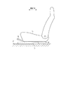
図1〜図5を参照して本発明の一実施形態について説明する。図1に示すように、車両フロア2には、第1レールとしてのロアレール3が前後方向に延在する態様で固定されるとともに、該ロアレール3には、第2レールとしてのアッパレール4がロアレール3に対し前後方向に相対移動可能に装着されている。
An embodiment of the present invention will be described with reference to FIGS. As shown in FIG. 1, a
なお、ロアレール3及びアッパレール4は、幅方向(図1において紙面に直交する方向)でそれぞれ対をなして配設されており、ここでは前方に向かって左側に配置されたものを示している。そして、両アッパレール4には、乗員の着座部を形成するシート5が固定・支持されている。ロアレール3及びアッパレール4の相対移動は基本的に係止状態にあって、該係止状態を解除するための解除ハンドル6が設けられている。
The
図2に示すように、ロアレール3は、板材からなり、幅方向両側で上下方向に延びる一対の第1側壁部11及びこれら第1側壁部11の基端(下端)間を連結する第1連結壁部12を有する。そして、各第1側壁部11の先端(上端)には、幅方向内側に張り出して更に第1側壁部11の基端側に折り返された第1折返し壁部13が連続形成されている。
As shown in FIG. 2, the
一方、前記アッパレール4は、板材からなり、図4(a)〜(c)に併せ示すように、ロアレール3の両第1折返し壁部13間で上下方向に延びる一対の第2側壁部14及びこれら第2側壁部14のロアレール3から離隔する基端(上端)間を連結する第2連結壁部15を有する。そして、各第2側壁部14の先端(下端)には、幅方向外側に張り出して更に第1側壁部11及び第1折返し壁部13に包囲されるように折り返された第2折返し壁部16が連続形成されている。
On the other hand, the
つまり、ロアレール3及びアッパレール4は、開口側が互いに突き合わされたU字状のレール断面をそれぞれ有しており、主として第1及び第2折返し壁部13,16との係合によって上下方向に抜け止めされている。これらロアレール3及びアッパレール4により形成されるレール断面は、矩形状をなすいわゆる箱形である。ロアレール3は、アッパレール4と協働して空間Sを構成する。
That is, the
なお、図3(a)及び図4(c)に示すように、各第2折返し壁部16及びこれに対向する第1側壁部11間には、前後一対の転動部材20が装着されており、アッパレール4は、ロアレール3との間で転動部材20を転動させる態様で、該ロアレール3に対し長手方向(前後方向)に摺動自在に支持されている。
As shown in FIGS. 3A and 4C, a pair of front and rear rolling
図3(a)(b)に示すように、ロアレール3の各第1折返し壁部13の長手方向中間部には、当該方向に所定の間隔をもってその先端(下端)から上向きに複数の切り欠き13aが形成されるとともに、各隣り合う切り欠き13a間に被係止部としての四角歯状のロック爪13bが形成されている。従って、複数のロック爪13bは、前記所定の間隔をもってロアレール3の長手方向に並設されている。また、ロアレール3の両第1折返し壁部13の長手方向両端部には、第1折返し壁部13の先端(下端)から更に下方にステップ状に延出する規制部17が形成されている。複数のロック爪13bの全てが、ロアレール3(第1折返し壁部13)の長手方向で両規制部17間に挟まれるように配置されていることはいうまでもない。
As shown in FIGS. 3 (a) and 3 (b), a plurality of notches are formed in the longitudinal intermediate portion of each first folded
一方、アッパレール4の各第2側壁部14の長手方向中間部には、当該方向に間隔をあけて一対の側壁部取付孔14aが形成されるとともに、アッパレール4の各第2折返し壁部16には、図4(a)に併せ示すように、各側壁部取付孔14aに幅方向で対向して折返し壁部取付孔16aが形成されている。側壁部取付孔14a及び折返し壁部取付孔16aは、上下方向で第1折返し壁部13(ロック爪13b)の下端及び規制部17の下端間に配置されている。
On the other hand, a pair of side wall attachment holes 14a are formed in the longitudinal direction intermediate portion of each second
そして、幅方向で隣り合う側壁部取付孔14a及び折返し壁部取付孔16aには、第2側壁部14及び第2折返し壁部16間に幅方向で橋渡しされる態様で係止部材40が挿設されている。この係止部材40は、例えば金属製の板材をU字状に折り曲げた板ばねからなる。係止部材40をアッパレール4に組み付ける際には、長手方向で両規制部17間に側壁部取付孔14a及び折返し壁部取付孔16aが配置されるように予めロアレール3及びアッパレール4を組み付けた状態で、アッパレール4内から幅方向外側に向けて側壁部取付孔14a及び折返し壁部取付孔16aに順次、係止部材40を挿入する。これにより、係止部材40は、アッパレール4に保持される。
Then, the locking
ここで、第2側壁部14及び第2折返し壁部16間に幅方向で橋渡しされる係止部材40が、ロアレール3及びアッパレール4の相対移動方向において、第1折返し壁部13の移動軌跡を開放するとともに規制部17の移動軌跡を遮ることはいうまでもない。従って、ロアレール3及びアッパレール4の相対移動時、該当の規制部17及び係止部材40が当接することで当該移動が係止される。これにより、ロアレール3及びアッパレール4の相対移動量が一定範囲内に制限される。
Here, the locking
図2に示すように、アッパレール4の両第2折返し壁部16には、前側の折返し壁部取付孔16aよりも更に前側で円形の軸取付孔16bがそれぞれ形成されるとともに、両折返し壁部取付孔16aの中間部で軸取付孔16bを中心とする扇状の折返し壁部透孔としての透孔16cがそれぞれ形成されている。なお、アッパレール4の第2連結壁部15には、軸取付孔16bよりも更に前側で幅方向に並設された一対のスリット状の支持孔21が形成されている。これら両支持孔21は前後方向に延在する。
As shown in FIG. 2, both the second folded
また、図3(a)に示すように、アッパレール4の両第2側壁部14には、前記軸取付孔16bと同心の円形の軸取付孔14bがそれぞれ形成されるとともに、両側壁部取付孔14aの中間部で軸取付孔14bを中心とする扇状の側壁部透孔としての透孔14cがそれぞれ形成されている。軸取付孔14b,16bは、互いに同等の内径を有しており、透孔14c,16cは、図4(b)に併せ示すように、互いに同等の形状を有して幅方向に対向している。すなわち、これら透孔14c,16cは、側面視で略合同の扇形状(閉じた形状)を呈する。
Further, as shown in FIG. 3 (a), both the second
図3(a)に示すように、アッパレール4内には、幅方向に中心線の延びる円柱状の支持ピン22により、ロックレバー30が回動自在に連結されている。すなわち、ロックレバー30は、図2に示すように、前後方向に延在するレバー部としての板材からなる柄部31を備える。この柄部31は、その長手方向全長に亘って一対の縦壁部32が幅方向に並設される態様で立設されている。これら両縦壁部32の幅方向の距離は、アッパレール4の両第2側壁部14の幅方向の距離よりも小さく設定されている。そして、両縦壁部32は、各々の前端部において保持壁33により上端縁間が幅方向に接続されるとともに、各々の後端部において連結壁及び規制壁部としての天板部34により上端縁間が幅方向に接続されている。そして、両縦壁部32には、支持ピン22(軸取付孔14b,16b)と同心の円形の軸取付孔35がそれぞれ形成されている。柄部31は、両軸取付孔14b,16bに両端部の嵌挿される支持ピン22が両軸取付孔35に挿入・軸支されることで、アッパレール4に回動自在に連結されている。
As shown in FIG. 3A, a
なお、図5(a)(b)に併せ示すように、保持壁33は、側面視において下向きに凸となる円弧形状を呈する。また、両縦壁部32は、前後方向における保持壁33及び軸取付孔35間で下端縁から互いに対向する幅方向内側に突設されたフランジ状の支持壁32aをそれぞれ有する。
As shown in FIGS. 5A and 5B, the holding
図5(c)に拡大して示すように、各縦壁部32には、天板部34の下方となる後端部において下端から下向きに一対の係合突片としての締結部36が前後方向に間隔をあけて突設されている、各締結部36は、前後方向に隣接配置された一対の締結片36a,36bを1組とする構成となっている。一方、ロックレバー30は、両透孔14c,16cを貫通する態様で前後方向及び幅方向に広がる平板状のロックプレート37を備える。このロックプレート37には、各締結部36に対向して上下方向に開口する係合孔としてのスリット状の締結孔38が合計4個形成されている。ロックプレート37は、その組付けにおいて、例えば予めアッパレール4に柄部31を軸支した状態で両透孔14c,16cに対し幅方向に挿入されて、両縦壁部32の下側に配置される。そして、この状態で、各締結孔38に該当の締結部36を高さ方向に挿入した後、例えば締結孔38を貫通した両締結片36a,36bの先端を前後方向に開くように圧潰させることで、柄部31に締結・固定される。従って、図4(b)に示すように、柄部31の後端部は、ロックプレート37、両縦壁部32及び天板部34と協働して略四角形の閉じた断面(閉断面)を構成する。
As shown in an enlarged view in FIG. 5C, each
また、ロックプレート37には、締結部36よりも幅方向外側で前後方向に並設された複数(3個)の係止部としてのロック孔39が前記所定の間隔をもって形成されている。図4(b)に併せ示すように、各ロック孔39は、第1折返し壁部13に対向して上下方向に開口しており、ロアレール3の長手方向で隣り合う複数(3個)のロック爪13bと合致可能な位置に配置されている。
Further, the
そして、図4(b)に実線で示すように、ロックプレート37が上昇するようにロックレバー30が支持ピン22周りに回動するとき、各ロック孔39に対応するロック爪13bを嵌入可能となっている。各ロック孔39に対応するロック爪13bを嵌入するとき、ロアレール3及びアッパレール4の相対移動が係止される。一方、図4(b)に2点鎖線で示すように、ロックプレート37が下降するようにロックレバー30が支持ピン22周りに回動するとき、各ロック孔39が対応するロック爪13bから外れるように設定されている。このとき、ロアレール3及びアッパレール4の相対移動の係止が解除される。
4B, when the
なお、各ロック孔39に対応するロック爪13bを嵌入する側(即ちロックプレート37が上昇する側)にロックレバー30が支持ピン22周りに回動するとき、天板部34の上面が第2連結壁部15の下面に近接(即ち非接触)している。そして、仮にロックレバー30が支持ピン22周りに本来の回動範囲よりも過剰に回動しようとすると、その弾性変形に伴い天板部34の上面がついには第2連結壁部15の下面に当接してその回動が係止される。これは、例えば両縦壁部32に対してロックプレート37を前述の態様で高さ方向に締結する際、柄部31の軸線周りの揺動を天板部34の上面が第2連結壁部15の下面に当接するまでの範囲に制限して当該締結作業を円滑に行うためである。換言すれば、ロックプレート37の挿通される両透孔14c,16cは、ロアレール3及びアッパレール4の相対移動の係止・解除時のロックプレート37の回動を許容する機能に加えて、両縦壁部32及びロックプレート37の締結作業時のロックプレート37の回動を一定範囲内で許容する機能を有している。
When the
アッパレール4内には、図2に示すように、1本の線材からなるワイヤスプリング50が配置されている。このワイヤスプリング50は、平面視において後側に開口する略コ字状に成形されており、左右対称で前後方向に延在する一対の延設部51を有するとともに、これら両延設部51の前端間を幅方向に接続する接続部52を有する。図3(a)に併せ示すように、ワイヤスプリング50は、各延設部51の長手方向中間部を上方に湾出してなる固定部53を有するとともに、該固定部53の後側で後方に向かって前記支持ピン22に時計回りに巻回してなるコイル部54を有する。そして、ワイヤスプリング50は、コイル部54を含む両延設部51の固定部53よりも後側の部位で第1付勢部55を形成するとともに、接続部52及び両延設部51の固定部53よりも前側の部位で第2付勢部56を形成する。
In the
ワイヤスプリング50は、各固定部53をアッパレール4の該当の支持孔21から突出させる態様で概ね柄部31内に配置され、コイル部54において支持ピン22を介してアッパレール4(両第2側壁部14)に支持されている。ワイヤスプリング50は、両固定部53を支持孔21の後端面に接触させており、コイル部54(支持ピン22)よりも後側で第1付勢部55の後端部をロックプレート37の下面に弾性的に接触させている。つまり、第1付勢部55は、アッパレール4との固定位置(固定部53)を支点にコイル部54を含めて曲げ変形されており、該固定位置を支点にロックレバー30を付勢している。従って、ロックレバー30は、ワイヤスプリング50(第1付勢部55)によりロックプレート37が上昇する側、即ち各ロック孔39に対応するロック爪13bが嵌入する側に回動付勢されている。
The
第1付勢部55にコイル部54を配設しているのは、第1付勢部55の前後方向への延出長を抑えながらも、曲げ変形時の弾性係数を実質的に低減させるためである。なお、ワイヤスプリング50の両固定部53は、支持孔21の前端面に非接触とされている。そして、ワイヤスプリング50(第2付勢部56)の接続部52は、保持壁33よりも前側に配置されている。
The
前記解除ハンドル6は、筒材を曲げ成形してなり、両アッパレール4の前側でこれらを幅方向に橋渡しするように成形されている。図2に示すように、解除ハンドル6の後方に延出する先端部61は、前記両縦壁部32間の幅方向の距離よりも外径の小さい円筒形状を呈しており、その下部には、幅方向に延在するスリット状の支持溝62が形成されている。
The release handle 6 is formed by bending a cylindrical material, and is formed so as to bridge them in the width direction on the front side of both
図3(a)に示すように、解除ハンドル6は、各先端部61が対応する柄部31(ロックレバー30)の保持壁33よりも下側、且つ、両支持壁32aよりも上側で両縦壁部32間に挿入されている。そして、先端部61は、ワイヤスプリング50の接続部52が支持溝62に嵌入することで係止・抜け止めされる。つまり、支持溝62の後端面62aは、解除ハンドル6の先端部61の外れを抑制するための接続部52との係合面となっている。また、両縦壁部32間に挿入された先端部61は、その後方延長線上に支持ピン22が対向するように配置されている。これにより、両縦壁部32間に先端部61が過剰に挿入されたとしても、支持ピン22に当接するまでの一定の範囲に制限されている。
As shown in FIG. 3A, the
そして、両縦壁部32間に挿入された先端部61は、支持溝62においてワイヤスプリング50により上昇するように付勢されることで、先端部61の上部及び下部を保持壁33の下面及び両支持壁32aの上面にそれぞれ当接させる態様で、実質的に支持ピン22周りにロックレバー30と一体回転するように保持される。つまり、ワイヤスプリング50は、解除ハンドル6がロックレバー30と一体回転するように解除ハンドル6を弾性的に保持する機能を併せ有している。ワイヤスプリング50の接続部52で先端部61(解除ハンドル6)を弾性的に保持しているのは、例えばロックレバー30に対して適度な節度感をもってこれに連結するためである。あるいは、意図しない外力などで先端部61(解除ハンドル6)が支持ピン22周りに本来の操作方向とは逆方向に回動しようとした際に、ロックレバー30に対する先端部61の揺動を許容してロックレバー30に過大な負荷が作用することを回避するためである。また、解除ハンドル6の先端部61を係止等するワイヤスプリング50(第2付勢部56)の接続部52を保持壁33よりも前側に配置したのは、解除ハンドル6がロックレバー30に対して接続部52を中心に揺動することを抑制するためである。
And the front-end | tip
次に、本実施形態の動作について説明する。
まず、解除ハンドル6の操作力が解放されているものとする。このとき、ワイヤスプリング50(第1付勢部55)の付勢力により、先端部61(解除ハンドル6)と一体でロックレバー30が支持ピン22周りにロックプレート37が上昇する側、即ち各ロック孔39が対応するロック爪13bに嵌入する側に回動されることで、前述の態様でロアレール3及びアッパレール4の相対移動が係止される。そして、アッパレール4に支持されるシート5の前後方向の位置が保持される。
Next, the operation of this embodiment will be described.
First, it is assumed that the operating force of the
ここで、解除ハンドル6がその前端を持ち上げるように操作されたとする。このとき、ワイヤスプリング50(第1付勢部55)の付勢力に抗して、先端部61(解除ハンドル6)と一体でロックレバー30が支持ピン22周りにロックプレート37が下降する側、即ち各ロック孔39が対応するロック爪13bから外れる側に回動されることで、前述の態様でロアレール3及びアッパレール4の相対移動の係止が解除される。そして、アッパレール4に支持されるシート5の前後方向の位置調整が可能になる。特に、これらの際には、両透孔14c,16c内でロックプレート37を空走させることで、該ロックプレート37との干渉が回避されている。
Here, it is assumed that the
以上詳述したように、本実施形態によれば、以下に示す効果が得られるようになる。
(1)本実施形態では、アッパレール4に連結された柄部31が支持ピン22周りに回動する際にロックプレート37との干渉を回避するための両透孔14c,16cは、閉じた形状を有することで、例えば従来例のように開いた(開口する)形状を有する場合に比べてアッパレール4の曲げ強度の低下を抑制することができる。
As described above in detail, according to the present embodiment, the following effects can be obtained.
(1) In the present embodiment, the two through
(2)本実施形態では、ロックプレート37、両縦壁部32及び天板部34が協働して閉断面を構成することで強度を増加することができ、例えばロックプレート37の幅方向端部が高さ方向に歪む変形を抑制することができる。そして、ロックプレート37によるロアレール3及びアッパレール4の相対移動の係止・解除の動作不良を抑制することができる。
(2) In the present embodiment, the
(3)本実施形態では、柄部31の両縦壁部32に対してロックプレート37を高さ方向に締結する際、柄部31の軸線周りの揺動は、天板部34の上面が第2連結壁部15の下面に当接するまでの範囲に制限される。従って、柄部31の両縦壁部32及びロックプレート37を円滑に締結することができる。
(3) In this embodiment, when the
(4)本実施形態では、柄部31及びロックプレート37を、複数の締結孔38をそれぞれ貫通した複数の締結部36の先端をそれぞれ圧潰させるという極めて簡易な手法で、高さ方向に締結することができる。
(4) In the present embodiment, the
なお、上記実施形態は以下のように変更してもよい。
・前記実施形態においては、連結壁として兼用される規制壁部としての天板部34を設けた。これに対し、連結壁及び規制壁部を個別に設けてもよいし、いずれか一方を割愛してもよい。例えば天板部34に加えて、両縦壁部32の高さ方向中間部間を連結する連結壁を設けてもよい。つまり、柄部31の後端部は、断面形状において、ロックプレート37と協働して「日」字状となる構成であってもよい。あるいは、天板部34に代えて、両縦壁部32の高さ方向中間部間を連結する連結壁を設けてもよい。つまり、柄部31の後端部は、断面形状において「H」字状であってもよい。これらのいずれの場合であっても、連結壁は、柄部31の両縦壁部32及びロックプレート37と協働して閉断面を構成することで強度を増加することができる。
In addition, you may change the said embodiment as follows.
In the above-described embodiment, the
・前記実施形態において、柄部31の両縦壁部32及びロックプレート37は、例えば溶接などで固着してもよい。
・前記実施形態において、柄部31に配設する複数の締結部を柱状(ピン状)として、複数の締結孔38をそれぞれ貫通した複数の柱状(ピン状)の締結部の先端をそれぞれ圧潰させることで、柄部31及びロックプレート37を高さ方向に締結してもよい。
In the embodiment, both the
In the above-described embodiment, the plurality of fastening portions disposed on the
・前記実施形態において、柄部31の各縦壁部32の前後方向に並設する締結部の個数は任意であり、柄部31及びロックプレート37の締結強度等に合わせて適宜の個数を採用すればよい。
-In the said embodiment, the number of the fastening parts arranged in parallel in the front-back direction of each
・前記実施形態において、ロックプレート37の前後方向に並設するロック孔39の個数は任意であり、ロアレール3及びアッパレール4の相対移動の係止強度や必要なロック解除ストロークの設定に合わせて適宜の個数を採用すればよい。
In the above-described embodiment, the number of the lock holes 39 arranged in the front-rear direction of the
・前記実施形態において、支持ピン22は、両端部をアッパレール4(両第2側壁部14)に固着してロックレバー30(両縦壁部32)に軸支させてもよいし、両端部をアッパレール4(両第2側壁部14)に軸支させてロックレバー30(両縦壁部32)に固着してもよい。
In the above-described embodiment, the
・前記実施形態において、ロアレール3又はアッパレール4は、複数枚の板材を溶接などで結合した構造であってもよい。
・前記実施形態において、ロアレール3及びアッパレール4と、車両フロア2及びシート5の固定関係(即ち上下の配置関係)は逆であってもよい。この場合、車両フロア2側に設置されるロックレバー30の解除操作は、例えばケーブルなどを通じて適宜の操作部材から行ってもよい。
In the embodiment, the
-In the said embodiment, the fixed relationship (namely, vertical arrangement relationship) of the
・前記実施形態において、ロアレール3及びアッパレール4(車両用シートスライド装置)は、シート5に対し各1本ずつ配設される構成であってもよいし、各3本以上ずつ配設される構成であってもよい。
In the above embodiment, the
・前記実施形態において、ロアレール及びアッパレールの相対移動に伴うシートの移動方向は、例えばその幅方向であってもよい。 -In the said embodiment, the moving direction of the sheet | seat accompanying the relative movement of a lower rail and an upper rail may be the width direction, for example.
2…車両フロア、5…シート、3…ロアレール(第1レール)、4…アッパレール(第2レール)、11…第1側壁部、12…第1連結壁部、13…第1折返し壁部、13b…ロック爪(被係止部)、14…第2側壁部、14c…透孔(側壁部透孔)、15…第2連結壁部、16…第2折返し壁部、16c…透孔(折返し壁部透孔)、22…支持ピン、30…ロックレバー、31…柄部(レバー部)、32…縦壁部、34…天板部(連結壁、規制壁部)、36…締結部(係合突片)、37…ロックプレート、38…締結孔(係合孔)、39…ロック孔(係止部)、50…ワイヤスプリング(付勢部材)。 DESCRIPTION OF SYMBOLS 2 ... Vehicle floor, 5 ... Seat, 3 ... Lower rail (1st rail), 4 ... Upper rail (2nd rail), 11 ... 1st side wall part, 12 ... 1st connection wall part, 13 ... 1st folding | turning wall part, 13b ... Lock claw (locked portion), 14 ... second side wall portion, 14c ... through hole (side wall portion through hole), 15 ... second connecting wall portion, 16 ... second folded wall portion, 16c ... through hole ( Folding wall part through-hole), 22 ... support pin, 30 ... lock lever, 31 ... handle part (lever part), 32 ... vertical wall part, 34 ... top plate part (connection wall, regulating wall part), 36 ... fastening part (Engagement protrusions), 37 ... lock plate, 38 ... fastening hole (engagement hole), 39 ... lock hole (engagement part), 50 ... wire spring (biasing member).
Claims (3)
前記車両フロア及び前記シートのいずれか他方に固定され、前記第1レールに対し相対移動可能に連結される第2レールとを備え、
前記第1レールは、幅方向に並設された一対の第1側壁部と、前記第2レールから離隔する前記両第1側壁部の基端間を連結する第1連結壁部と、前記両第1側壁部の先端から互いの対向する幅方向内側にそれぞれ張り出して更に該第1側壁部の基端側に折り返された一対の第1折返し壁部と、前記両第1折返し壁部の先端に形成された被係止部とを有し、
前記第2レールは、前記両第1側壁部間で幅方向に並設された一対の第2側壁部と、前記第1レールから離隔する前記両第2側壁部の基端間を連結する第2連結壁部と、前記両第2側壁部の先端から互いに離隔する幅方向外側にそれぞれ張り出して更に前記第1側壁部及び前記第1折返し壁部に包囲されるように折り返された一対の第2折返し壁部と、幅方向に対向配置されて前記各第2側壁部及び前記各第2折返し壁部にそれぞれ形成された一対の側壁部透孔及び折返し壁部透孔とを有し、
前記両第2側壁部間に配置されて幅方向に延びる軸線周りに前記第2レールに回動自在に連結されるレバー部と、
前記レバー部の先端部に固着され、前記両第1側壁部間に配置されて前記両側壁部透孔及び前記両折返し壁部透孔に跨って幅方向に広がるロックプレートと、
前記ロックプレートの幅方向両側縁部に形成され、前記レバー部の一側方向への回動に伴い前記被係止部と係合し、前記レバー部の他側方向への回動に伴い前記被係止部との係合を解除する係止部と、
前記係止部が前記被係止部に係合する側に付勢する付勢部材とを備え、
前記レバー部は、
前記両第2側壁部間で幅方向に並設される一対の縦壁部において前記第2レールに回動自在に連結され、且つ、前記両縦壁部の前記第2連結壁部から離隔する先端において前記ロックプレートと高さ方向に締結されており、
少なくとも前記ロックプレートの締結位置で前記両縦壁部の前記第2連結壁部に近付く基端間を連結する規制壁部を有し、
前記両縦壁部の前記第2連結壁部から離隔する先端にそれぞれ突設された複数の係合突片と、
前記複数の係合突片に高さ方向に対向して前記ロックプレートにそれぞれ形成された複数の係合孔とを備え、
前記レバー部及び前記ロックプレートは、前記複数の係合孔をそれぞれ貫通した前記複数の係合突片の先端をそれぞれ圧潰させることで高さ方向に締結されていることを特徴とする車両用シートスライド装置。 A first rail fixed to either the vehicle floor or the seat;
A second rail fixed to one of the vehicle floor and the seat and connected to the first rail so as to be relatively movable;
The first rail includes a pair of first side wall portions arranged side by side in a width direction, a first connection wall portion connecting between base ends of the first side wall portions spaced apart from the second rail, A pair of first folded wall portions projecting inward in the width direction opposite to each other from the distal ends of the first side wall portions and folded back to the proximal end side of the first side wall portions, and the distal ends of the first folded wall portions And a locked portion formed on
The second rail connects a pair of second side wall portions arranged in parallel in the width direction between the first side wall portions and a base end of the second side wall portions separated from the first rail. A pair of second connecting wall portions and a pair of second wall portions projecting outward in the width direction spaced apart from the ends of the second side wall portions and folded back so as to be surrounded by the first side wall portion and the first folding wall portion. Two folded wall portions, and a pair of side wall through holes and folded wall portion through holes that are opposed to each other in the width direction and are respectively formed in the second side wall portions and the second folded wall portions,
A lever portion disposed between the second side wall portions and rotatably connected to the second rail around an axis extending in the width direction;
A lock plate fixed to the tip of the lever portion, disposed between the first side wall portions and extending in the width direction across the side wall through holes and the folded wall through holes;
The lock plate is formed at both side edges in the width direction, engages with the locked portion as the lever portion rotates in one side direction, and moves as the lever portion rotates in the other direction. A locking part for releasing the engagement with the locked part;
A biasing member that biases the locking portion toward the side that engages the locked portion ;
The lever portion is
A pair of vertical wall portions arranged in parallel in the width direction between the second side wall portions are rotatably connected to the second rail, and are separated from the second connection wall portions of the two vertical wall portions. It is fastened to the lock plate at the tip in the height direction,
A restriction wall portion that connects between the proximal ends of the vertical wall portions approaching the second connection wall portion at least at the fastening position of the lock plate;
A plurality of engaging protrusions each protruding at the tip of each of the vertical wall portions separated from the second connection wall portion;
A plurality of engagement holes respectively formed in the lock plate so as to face the plurality of engagement protrusions in the height direction;
The vehicle seat, wherein the lever portion and the lock plate are fastened in a height direction by crushing tips of the plurality of engagement protrusions that respectively penetrate the plurality of engagement holes. Slide device.
前記車両フロア及び前記シートのいずれか他方に固定され、前記第1レールに対し相対移動可能に連結される第2レールとを備え、
前記第1レールは、幅方向に並設された一対の第1側壁部と、前記第2レールから離隔する前記両第1側壁部の基端間を連結する第1連結壁部と、前記両第1側壁部の先端から互いの対向する幅方向内側にそれぞれ張り出して更に該第1側壁部の基端側に折り返された一対の第1折返し壁部と、前記両第1折返し壁部の先端に形成された被係止部とを有し、
前記第2レールは、前記両第1側壁部間で幅方向に並設された一対の第2側壁部と、前記第1レールから離隔する前記両第2側壁部の基端間を連結する第2連結壁部と、前記両第2側壁部の先端から互いに離隔する幅方向外側にそれぞれ張り出して更に前記第1側壁部及び前記第1折返し壁部に包囲されるように折り返された一対の第2折返し壁部と、幅方向に対向配置されて前記各第2側壁部及び前記各第2折返し壁部にそれぞれ形成された一対の側壁部透孔及び折返し壁部透孔とを有し、
前記両第2側壁部間に配置されて幅方向に延びる軸線周りに前記第2レールに回動自在に連結されるレバー部と、
前記レバー部の先端部に固着され、前記両第1側壁部間に配置されて前記両側壁部透孔及び前記両折返し壁部透孔に跨って幅方向に広がるロックプレートと、
前記ロックプレートの幅方向両側縁部に形成され、前記レバー部の一側方向への回動に伴い前記被係止部と係合し、前記レバー部の他側方向への回動に伴い前記被係止部との係合を解除する係止部と、
前記係止部が前記被係止部に係合する側に付勢する付勢部材とを備え、
前記レバー部の先端部には、係合突片が突設され、
前記ロックプレートには、係合孔が形成され、
前記レバー部及び前記ロックプレートは、前記係合孔を貫通した前記係合突片の先端を圧潰させることで固着されていることを特徴とする車両用シートスライド装置。 A first rail fixed to either the vehicle floor or the seat;
A second rail fixed to one of the vehicle floor and the seat and connected to the first rail so as to be relatively movable;
The first rail includes a pair of first side wall portions arranged side by side in a width direction, a first connection wall portion connecting between base ends of the first side wall portions spaced apart from the second rail, A pair of first folded wall portions projecting inward in the width direction opposite to each other from the distal ends of the first side wall portions and folded back to the proximal end side of the first side wall portions, and the distal ends of the first folded wall portions And a locked portion formed on
The second rail connects a pair of second side wall portions arranged in parallel in the width direction between the first side wall portions and a base end of the second side wall portions separated from the first rail. A pair of second connecting wall portions and a pair of second wall portions projecting outward in the width direction spaced apart from the ends of the second side wall portions and folded back so as to be surrounded by the first side wall portion and the first folding wall portion. Two folded wall portions, and a pair of side wall through holes and folded wall portion through holes that are opposed to each other in the width direction and are respectively formed in the second side wall portions and the second folded wall portions,
A lever portion disposed between the second side wall portions and rotatably connected to the second rail around an axis extending in the width direction;
A lock plate fixed to the tip of the lever portion, disposed between the first side wall portions and extending in the width direction across the side wall through holes and the folded wall through holes;
The lock plate is formed at both side edges in the width direction, engages with the locked portion as the lever portion rotates in one side direction, and moves as the lever portion rotates in the other direction. A locking part for releasing the engagement with the locked part;
A biasing member that biases the locking portion toward the side that engages the locked portion ;
At the tip of the lever part, an engaging protrusion is provided,
The lock plate is formed with an engagement hole,
The vehicle seat slide device according to claim 1, wherein the lever portion and the lock plate are fixed by crushing a tip end of the engagement protrusion penetrating the engagement hole .
前記レバー部は、
前記両第2側壁部間で幅方向に並設される一対の縦壁部において前記第2レールに回動自在に連結され、且つ、前記両縦壁部の前記第2連結壁部から離隔する先端において前記ロックプレートと高さ方向に締結されており、
前記レバー部は、前記ロックプレートと前記両縦壁部とともに閉断面を構成する連結壁を有することを特徴とする車両用シートスライド装置。 In the vehicle seat slide device according to claim 1 or 2 ,
The lever portion is
A pair of vertical wall portions arranged in parallel in the width direction between the second side wall portions are rotatably connected to the second rail, and are separated from the second connection wall portions of the two vertical wall portions. It is fastened to the lock plate at the tip in the height direction,
The said lever part has the connection wall which comprises a closed cross section with the said lock plate and the said both vertical wall part, The vehicle seat slide apparatus characterized by the above-mentioned.
Priority Applications (5)
| Application Number | Priority Date | Filing Date | Title |
|---|---|---|---|
| JP2011154133A JP5659974B2 (en) | 2011-07-12 | 2011-07-12 | Vehicle seat slide device |
| EP12811692.8A EP2733013B1 (en) | 2011-07-12 | 2012-06-27 | Seat sliding device for vehicle |
| PCT/JP2012/066427 WO2013008630A1 (en) | 2011-07-12 | 2012-06-27 | Seat sliding device for vehicle |
| US14/131,350 US9315119B2 (en) | 2011-07-12 | 2012-06-27 | Seat sliding device for vehicle |
| CN201290000626.7U CN203844632U (en) | 2011-07-12 | 2012-06-27 | Seat sliding device for vehicle |
Applications Claiming Priority (1)
| Application Number | Priority Date | Filing Date | Title |
|---|---|---|---|
| JP2011154133A JP5659974B2 (en) | 2011-07-12 | 2011-07-12 | Vehicle seat slide device |
Publications (2)
| Publication Number | Publication Date |
|---|---|
| JP2013018401A JP2013018401A (en) | 2013-01-31 |
| JP5659974B2 true JP5659974B2 (en) | 2015-01-28 |
Family
ID=47505927
Family Applications (1)
| Application Number | Title | Priority Date | Filing Date |
|---|---|---|---|
| JP2011154133A Expired - Fee Related JP5659974B2 (en) | 2011-07-12 | 2011-07-12 | Vehicle seat slide device |
Country Status (5)
| Country | Link |
|---|---|
| US (1) | US9315119B2 (en) |
| EP (1) | EP2733013B1 (en) |
| JP (1) | JP5659974B2 (en) |
| CN (1) | CN203844632U (en) |
| WO (1) | WO2013008630A1 (en) |
Families Citing this family (24)
| Publication number | Priority date | Publication date | Assignee | Title |
|---|---|---|---|---|
| US9394608B2 (en) * | 2009-04-06 | 2016-07-19 | Asm America, Inc. | Semiconductor processing reactor and components thereof |
| JP5621724B2 (en) * | 2011-07-12 | 2014-11-12 | アイシン精機株式会社 | Vehicle seat slide device |
| JP5475185B1 (en) * | 2012-10-10 | 2014-04-16 | 岐阜車体工業株式会社 | Lock mechanism in seat track slide device |
| FR2999123B1 (en) * | 2012-12-10 | 2016-12-30 | Faurecia Sieges Dautomobile | SLIDE FOR VEHICLE SEAT AND VEHICLE SEAT COMPRISING SUCH A SLIDER. |
| US10214119B2 (en) | 2013-09-20 | 2019-02-26 | Lear Corporation | Track adjuster |
| JP6253936B2 (en) * | 2013-09-30 | 2017-12-27 | トヨタ紡織株式会社 | Vehicle seat |
| EP3061644A4 (en) | 2013-10-25 | 2016-11-09 | Aisin Seiki | Seat slide device |
| BR112016008128B1 (en) * | 2013-10-25 | 2022-02-01 | Aisin Seiki Kabushiki Kaisha | SEAT SLIDING DEVICE |
| WO2015060436A1 (en) * | 2013-10-25 | 2015-04-30 | アイシン精機 株式会社 | Vehicular seat slide device |
| JP6320187B2 (en) * | 2014-06-16 | 2018-05-09 | シロキ工業株式会社 | Assembly device and assembly method for vehicle seat slide device |
| KR101984637B1 (en) * | 2014-12-12 | 2019-05-31 | 애디언트 룩셈부르크 홀딩 에스.아 알.엘. | Longitudinal adjuster for a vehicle seat, and vehicle seat |
| JP2017043325A (en) * | 2015-08-28 | 2017-03-02 | アイシン精機株式会社 | Vehicular seat slide device |
| JP6587893B2 (en) * | 2015-10-12 | 2019-10-09 | デルタ工業株式会社 | Seat slide adjuster |
| DE102017208725A1 (en) * | 2016-05-26 | 2017-11-30 | Toyota Boshoku Kabushiki Kaisha | Sitzlängsverstellvorrichtung |
| DE102017204884A1 (en) * | 2017-03-23 | 2018-09-27 | Lear Corporation | Schieneneinstellvorrichtung |
| BR102017006962A2 (en) * | 2017-04-05 | 2018-10-30 | Aethra Sist Automotivos S/A | longitudinal movement and adjustment device of motor vehicle seats |
| US10940775B2 (en) * | 2018-03-16 | 2021-03-09 | Tf-Metal Co., Ltd. | Seat slide device |
| JP7141278B2 (en) * | 2018-08-27 | 2022-09-22 | トヨタ車体精工株式会社 | seat slide device |
| CN109017467A (en) * | 2018-09-30 | 2018-12-18 | 湖北航嘉麦格纳座椅系统有限公司 | Vehicle seat and its Manual sliding track mechanism |
| JP7173884B2 (en) * | 2019-01-25 | 2022-11-16 | トヨタ紡織株式会社 | slide device |
| JP7186102B2 (en) | 2019-01-25 | 2022-12-08 | トヨタ紡織株式会社 | slide device |
| JP7293664B2 (en) * | 2019-01-25 | 2023-06-20 | トヨタ紡織株式会社 | slide device |
| JP7173885B2 (en) * | 2019-01-25 | 2022-11-16 | トヨタ紡織株式会社 | slide device |
| WO2024015033A1 (en) * | 2022-07-13 | 2024-01-18 | Özkiliç Otomoti̇v Ve Koltuk Si̇stemleri̇ Sanayi̇ Ti̇caret Li̇mi̇ted Şi̇rketi̇ | Rail mechanism used in vehicle seats |
Family Cites Families (4)
| Publication number | Priority date | Publication date | Assignee | Title |
|---|---|---|---|---|
| JP4106137B2 (en) * | 1998-11-13 | 2008-06-25 | アイシン精機株式会社 | Vehicle seat slide device |
| JP4355963B2 (en) * | 2007-01-30 | 2009-11-04 | 株式会社今仙電機製作所 | Slide rail device |
| JP5448694B2 (en) * | 2009-10-07 | 2014-03-19 | デルタ工業株式会社 | Assembly structure of unlocking operation member for vehicle seat and lock / unlock device for vehicle seat |
| JP4947123B2 (en) * | 2009-11-04 | 2012-06-06 | アイシン精機株式会社 | Vehicle sliding device |
-
2011
- 2011-07-12 JP JP2011154133A patent/JP5659974B2/en not_active Expired - Fee Related
-
2012
- 2012-06-27 CN CN201290000626.7U patent/CN203844632U/en not_active Expired - Fee Related
- 2012-06-27 EP EP12811692.8A patent/EP2733013B1/en not_active Not-in-force
- 2012-06-27 WO PCT/JP2012/066427 patent/WO2013008630A1/en active Application Filing
- 2012-06-27 US US14/131,350 patent/US9315119B2/en active Active
Also Published As
| Publication number | Publication date |
|---|---|
| EP2733013A4 (en) | 2015-03-04 |
| CN203844632U (en) | 2014-09-24 |
| US9315119B2 (en) | 2016-04-19 |
| EP2733013B1 (en) | 2018-06-13 |
| JP2013018401A (en) | 2013-01-31 |
| US20140145054A1 (en) | 2014-05-29 |
| WO2013008630A1 (en) | 2013-01-17 |
| EP2733013A1 (en) | 2014-05-21 |
Similar Documents
| Publication | Publication Date | Title |
|---|---|---|
| JP5659974B2 (en) | Vehicle seat slide device | |
| JP5621724B2 (en) | Vehicle seat slide device | |
| JP5830954B2 (en) | Vehicle seat slide device | |
| JP4986036B2 (en) | Vehicle seat slide mechanism | |
| EP2371614B1 (en) | Seat slide apparatus for vehicle | |
| JP5900288B2 (en) | Vehicle seat slide device | |
| JP6089759B2 (en) | Vehicle seat slide device | |
| JP5572381B2 (en) | Vehicle seat truck | |
| JP6217501B2 (en) | Slide rail | |
| JP6028614B2 (en) | Vehicle seat slide device | |
| EP2371617B1 (en) | Seat slide apparatus for vehicle | |
| WO2013035414A1 (en) | Vehicle seat sliding device | |
| JP2013169892A (en) | Seat sliding device for vehicle | |
| US8894107B2 (en) | Lock apparatus | |
| JP2010100077A (en) | Slide rail device | |
| JP5991207B2 (en) | Slide rail | |
| JP6160337B2 (en) | Vehicle seat slide device | |
| JP5974815B2 (en) | Vehicle seat slide device | |
| JP5488555B2 (en) | Vehicle seat slide device | |
| JP5488554B2 (en) | Vehicle seat slide device | |
| US20230211708A1 (en) | Seat slide device | |
| JP6492876B2 (en) | Vehicle seat slide device | |
| JP2014097724A (en) | Seat slide device for vehicle | |
| WO2013035536A1 (en) | Seat slide device for vehicle | |
| JP2002104030A (en) | Slide lock device of seat for vehicle |
Legal Events
| Date | Code | Title | Description |
|---|---|---|---|
| A621 | Written request for application examination |
Free format text: JAPANESE INTERMEDIATE CODE: A621 Effective date: 20130903 |
|
| A131 | Notification of reasons for refusal |
Free format text: JAPANESE INTERMEDIATE CODE: A131 Effective date: 20140819 |
|
| A521 | Request for written amendment filed |
Free format text: JAPANESE INTERMEDIATE CODE: A523 Effective date: 20141010 |
|
| TRDD | Decision of grant or rejection written | ||
| A01 | Written decision to grant a patent or to grant a registration (utility model) |
Free format text: JAPANESE INTERMEDIATE CODE: A01 Effective date: 20141104 |
|
| A61 | First payment of annual fees (during grant procedure) |
Free format text: JAPANESE INTERMEDIATE CODE: A61 Effective date: 20141117 |
|
| R151 | Written notification of patent or utility model registration |
Ref document number: 5659974 Country of ref document: JP Free format text: JAPANESE INTERMEDIATE CODE: R151 |
|
| LAPS | Cancellation because of no payment of annual fees |