JP5734890B2 - Slide rail device for vehicle - Google Patents
Slide rail device for vehicle Download PDFInfo
- Publication number
- JP5734890B2 JP5734890B2 JP2012030045A JP2012030045A JP5734890B2 JP 5734890 B2 JP5734890 B2 JP 5734890B2 JP 2012030045 A JP2012030045 A JP 2012030045A JP 2012030045 A JP2012030045 A JP 2012030045A JP 5734890 B2 JP5734890 B2 JP 5734890B2
- Authority
- JP
- Japan
- Prior art keywords
- lock
- spring
- handle
- rail
- lever
- Prior art date
- Legal status (The legal status is an assumption and is not a legal conclusion. Google has not performed a legal analysis and makes no representation as to the accuracy of the status listed.)
- Active
Links
- 230000007246 mechanism Effects 0.000 claims description 15
- 230000001105 regulatory effect Effects 0.000 claims description 4
- 239000002184 metal Substances 0.000 description 9
- 230000000052 comparative effect Effects 0.000 description 8
- 230000005489 elastic deformation Effects 0.000 description 7
- 238000005452 bending Methods 0.000 description 4
- 238000010586 diagram Methods 0.000 description 4
- 230000000630 rising effect Effects 0.000 description 4
- 230000037431 insertion Effects 0.000 description 2
- 238000003780 insertion Methods 0.000 description 2
- 238000000465 moulding Methods 0.000 description 2
- 238000009434 installation Methods 0.000 description 1
- 239000000463 material Substances 0.000 description 1
- 230000002093 peripheral effect Effects 0.000 description 1
Images


Classifications
-
- B—PERFORMING OPERATIONS; TRANSPORTING
- B60—VEHICLES IN GENERAL
- B60N—SEATS SPECIALLY ADAPTED FOR VEHICLES; VEHICLE PASSENGER ACCOMMODATION NOT OTHERWISE PROVIDED FOR
- B60N2/00—Seats specially adapted for vehicles; Arrangement or mounting of seats in vehicles
- B60N2/02—Seats specially adapted for vehicles; Arrangement or mounting of seats in vehicles the seat or part thereof being movable, e.g. adjustable
- B60N2/04—Seats specially adapted for vehicles; Arrangement or mounting of seats in vehicles the seat or part thereof being movable, e.g. adjustable the whole seat being movable
- B60N2/06—Seats specially adapted for vehicles; Arrangement or mounting of seats in vehicles the seat or part thereof being movable, e.g. adjustable the whole seat being movable slidable
- B60N2/07—Slide construction
- B60N2/0702—Slide construction characterised by its cross-section
- B60N2/0705—Slide construction characterised by its cross-section omega-shaped
-
- B—PERFORMING OPERATIONS; TRANSPORTING
- B60—VEHICLES IN GENERAL
- B60N—SEATS SPECIALLY ADAPTED FOR VEHICLES; VEHICLE PASSENGER ACCOMMODATION NOT OTHERWISE PROVIDED FOR
- B60N2/00—Seats specially adapted for vehicles; Arrangement or mounting of seats in vehicles
- B60N2/02—Seats specially adapted for vehicles; Arrangement or mounting of seats in vehicles the seat or part thereof being movable, e.g. adjustable
- B60N2/04—Seats specially adapted for vehicles; Arrangement or mounting of seats in vehicles the seat or part thereof being movable, e.g. adjustable the whole seat being movable
- B60N2/06—Seats specially adapted for vehicles; Arrangement or mounting of seats in vehicles the seat or part thereof being movable, e.g. adjustable the whole seat being movable slidable
- B60N2/08—Seats specially adapted for vehicles; Arrangement or mounting of seats in vehicles the seat or part thereof being movable, e.g. adjustable the whole seat being movable slidable characterised by the locking device
-
- B—PERFORMING OPERATIONS; TRANSPORTING
- B60—VEHICLES IN GENERAL
- B60N—SEATS SPECIALLY ADAPTED FOR VEHICLES; VEHICLE PASSENGER ACCOMMODATION NOT OTHERWISE PROVIDED FOR
- B60N2/00—Seats specially adapted for vehicles; Arrangement or mounting of seats in vehicles
- B60N2/02—Seats specially adapted for vehicles; Arrangement or mounting of seats in vehicles the seat or part thereof being movable, e.g. adjustable
- B60N2/04—Seats specially adapted for vehicles; Arrangement or mounting of seats in vehicles the seat or part thereof being movable, e.g. adjustable the whole seat being movable
- B60N2/06—Seats specially adapted for vehicles; Arrangement or mounting of seats in vehicles the seat or part thereof being movable, e.g. adjustable the whole seat being movable slidable
- B60N2/07—Slide construction
- B60N2/0702—Slide construction characterised by its cross-section
- B60N2/0715—C or U-shaped
-
- B—PERFORMING OPERATIONS; TRANSPORTING
- B60—VEHICLES IN GENERAL
- B60N—SEATS SPECIALLY ADAPTED FOR VEHICLES; VEHICLE PASSENGER ACCOMMODATION NOT OTHERWISE PROVIDED FOR
- B60N2/00—Seats specially adapted for vehicles; Arrangement or mounting of seats in vehicles
- B60N2/02—Seats specially adapted for vehicles; Arrangement or mounting of seats in vehicles the seat or part thereof being movable, e.g. adjustable
- B60N2/04—Seats specially adapted for vehicles; Arrangement or mounting of seats in vehicles the seat or part thereof being movable, e.g. adjustable the whole seat being movable
- B60N2/06—Seats specially adapted for vehicles; Arrangement or mounting of seats in vehicles the seat or part thereof being movable, e.g. adjustable the whole seat being movable slidable
- B60N2/08—Seats specially adapted for vehicles; Arrangement or mounting of seats in vehicles the seat or part thereof being movable, e.g. adjustable the whole seat being movable slidable characterised by the locking device
- B60N2/0812—Location of the latch
- B60N2/0818—Location of the latch inside the rail
-
- B—PERFORMING OPERATIONS; TRANSPORTING
- B60—VEHICLES IN GENERAL
- B60N—SEATS SPECIALLY ADAPTED FOR VEHICLES; VEHICLE PASSENGER ACCOMMODATION NOT OTHERWISE PROVIDED FOR
- B60N2/00—Seats specially adapted for vehicles; Arrangement or mounting of seats in vehicles
- B60N2/02—Seats specially adapted for vehicles; Arrangement or mounting of seats in vehicles the seat or part thereof being movable, e.g. adjustable
- B60N2/04—Seats specially adapted for vehicles; Arrangement or mounting of seats in vehicles the seat or part thereof being movable, e.g. adjustable the whole seat being movable
- B60N2/06—Seats specially adapted for vehicles; Arrangement or mounting of seats in vehicles the seat or part thereof being movable, e.g. adjustable the whole seat being movable slidable
- B60N2/08—Seats specially adapted for vehicles; Arrangement or mounting of seats in vehicles the seat or part thereof being movable, e.g. adjustable the whole seat being movable slidable characterised by the locking device
- B60N2/0831—Movement of the latch
- B60N2/0862—Movement of the latch sliding
- B60N2/0875—Movement of the latch sliding in a vertical direction
Description
本発明は、シートをスライド可能に支持する車両用スライドレール装置に関する。 The present invention relates to a vehicle slide rail device that slidably supports a seat.
特許文献1の車両用スライドレール装置は、前後方向に延びかつ車内床面に固定した左右一対のロアレールと、シートの座部を支持し、かつ左右のロアレールにスライド可能に支持した左右一対のアッパレールと、アッパレールとロアレールの間に設けた、アッパレールのスライドを規制又は規制解除するロック機構と、アッパレールの内部空間に挿入した前面及び下面が開口する左右一対のロック操作レバー(ロック解除レバー)と、左右の後端部を左右のロック操作レバーの内部空間の前端部にそれぞれ挿入したループハンドルと、を備えている。ロック操作レバーはアッパレールに対して上記ロック機構によるスライド規制を許容するロック位置と、前部が該ロック位置に比べて上方に移動して該スライド規制を解除するアンロック位置と、の間を上下回転可能である。 The vehicle slide rail device of Patent Document 1 includes a pair of left and right lower rails that extend in the front-rear direction and is fixed to a vehicle interior floor surface, and a pair of left and right upper rails that support a seat portion of the seat and are slidably supported on the left and right lower rails. A lock mechanism for restricting or releasing the slide of the upper rail provided between the upper rail and the lower rail, a pair of left and right lock operation levers (lock release levers) opened in the front space and the lower surface inserted into the inner space of the upper rail, A loop handle having left and right rear ends inserted into front ends of the inner space of the left and right lock operation levers, respectively. The lock control lever moves up and down between a lock position that allows the upper rail to be slid by the lock mechanism and an unlock position where the front part moves upward relative to the lock position and releases the slide restriction. It can be rotated.
さらにこのスライドレール装置は、ロック操作レバーの内部空間の前端部に取り付けた線バネからなるトーションスプリングを備えている。トーションスプリングは、ループハンドルをロック操作レバーに取り付ける前にロック操作レバーの内部空間に取り付けるものであり、自身の複数箇所をロック操作レバーに係合することにより、ロック操作レバーに対して前後方向及び上下方向に相対移動不能となっている。そしてトーションスプリングをロック操作レバーの内部空間の前端部に取り付けた後に、ループハンドルの後端部をロック操作レバーの前端開口からロック操作レバーの内部空間に挿入すると、トーションスプリングがループハンドルの後端部と係合することによりループハンドルの後端部を支持する。
乗客がループハンドルを操作しないときは、ロック機構によってアッパレールのロアレールに対するスライドが規制される。一方、乗客がループハンドルを上方に回転操作すると、ロック位置に位置していたロック操作レバーがアンロック位置まで回転してロック機構によるスライド規制を解除するので、アッパレールがロアレールに対してスライド可能になる。
The slide rail device further includes a torsion spring formed of a wire spring attached to the front end portion of the internal space of the lock operation lever. The torsion spring is attached to the inner space of the lock operation lever before the loop handle is attached to the lock operation lever. Relative movement is impossible in the vertical direction. After attaching the torsion spring to the front end of the inner space of the lock operating lever, when the rear end of the loop handle is inserted into the inner space of the lock operating lever from the front end opening of the lock operating lever, the torsion spring is moved to the rear end of the loop handle. The rear end portion of the loop handle is supported by engaging the portion.
When the passenger does not operate the loop handle, sliding of the upper rail with respect to the lower rail is restricted by the lock mechanism. On the other hand, when the passenger rotates the loop handle upward, the lock operation lever located at the lock position rotates to the unlock position and the slide restriction by the lock mechanism is released, so the upper rail can slide relative to the lower rail. Become.
特許文献1の車両用スライドレール装置は、ループハンドルをロック操作レバーに取り付ける前に、トーションスプリングをロック操作レバーの内部空間の前端部に取り付ける構造である。しかしトーションスプリングをロック操作レバーの内部空間に取り付けるためには、トーションスプリングを弾性変形させてその複数箇所をロック操作レバーの複数の箇所に係合させる必要があるため、トーションスプリングのロック操作レバーに対する取付作業は容易でない。そのため車両用スライドレール装置の組立作業を迅速に行うのが難しかった。 The vehicle slide rail device of Patent Document 1 has a structure in which a torsion spring is attached to the front end portion of the internal space of the lock operation lever before the loop handle is attached to the lock operation lever. However, in order to mount the torsion spring in the internal space of the lock operation lever, it is necessary to elastically deform the torsion spring and engage the plurality of locations with the plurality of locations of the lock operation lever. Installation work is not easy. Therefore, it has been difficult to quickly assemble the slide rail device for a vehicle.
本発明は、ハンドルをロック操作レバーに対して取り付けるための付勢バネを、ロック操作レバーに対して前後方向に相対移動せずかつロック操作レバーの下面開口から下方に脱落することが無いように簡単に取り付けることが可能な車両用スライドレール装置を提供することを目的とする。 In the present invention, the urging spring for attaching the handle to the lock operation lever does not move relative to the lock operation lever in the front-rear direction and does not fall off from the lower surface opening of the lock operation lever. An object of the present invention is to provide a slide rail device for a vehicle that can be easily attached.
本発明の車両用スライドレール装置は、前後方向に延びる、車両床面に対して移動不能なロアレールと、シートを支持すると共に上記ロアレールに前後方向にスライド可能として支持したアッパレールと、上記アッパレールとロアレールの間に設けた、アッパレールのスライドを規制又は規制解除するロック機構と、上記アッパレールの内部空間に挿入した、前面及び下面が開口し、かつ下縁部に第一係止部を有するロック操作レバーと、該ロック操作レバーが上記内部空間の所定位置に位置するときに、該ロック操作レバーを上記アッパレールに対して、該ロック機構によるスライド規制を許容するロック位置と前部が該ロック位置に比べて上方に移動して該スライド規制を解除するアンロック位置とに上下回転可能として支持する回転支持手段と、自身の後端部を上記ロック操作レバーの内部空間に挿入し、かつ自身の前端部が上記ロック操作レバーの前面開口から前方に突出するハンドルと、上記第一係止部に対して前後動を規制可能に係合する第一係合部を備え、上記ロック操作レバーの上記内部空間において上記ハンドルの上記後端部を前後方向への相対移動を規制しながら支持する付勢バネと、上記アッパレールに設けた、上記回転支持手段が上記ロック操作レバーを支持したときに、上記付勢バネの直下に位置して該付勢バネが上記ロック操作レバーの下面開口から下方に脱落するのを規制するバネ支持部と、を備え、上記付勢バネが、上記ハンドルの直下に位置しかつ上記バネ支持部に対して上方から接触するバネ支持部側接触部と、上記ハンドルの直下に位置しかつ該バネ支持部側接触部から上方及び前後方向に離間した位置において上記ハンドルの下面に対して下方から接触するハンドル側接触部と、を備えることを特徴としている。 The vehicle slide rail device according to the present invention includes a lower rail that extends in the front-rear direction and is immovable with respect to the vehicle floor, an upper rail that supports the seat and is slidable in the front-rear direction, and the upper rail and the lower rail. A lock mechanism for restricting or releasing the slide of the upper rail, and a lock operation lever inserted into the inner space of the upper rail, having a front surface and a lower surface opened, and having a first locking portion at the lower edge portion When the lock operation lever is located at a predetermined position in the internal space, the lock operation lever allows the lock mechanism to be slid with respect to the upper rail, and a lock position and a front portion are compared with the lock position. Rotating support that is supported so that it can be rotated up and down at the unlock position where the slide restriction is released. And means, the rear end portion of itself is inserted into the inner space of the lock operating lever, and a handle front portion of itself protrudes forward from the front opening of the lock lever with respect to said first locking portion A biasing spring that includes a first engagement portion that engages the back and forth movement in a restrictable manner, and supports the rear end portion of the handle in the internal space of the lock operation lever while restricting relative movement in the front and rear direction; When the rotation support means provided on the upper rail supports the lock operating lever, the biasing spring is located directly below the biasing spring and drops downward from the lower surface opening of the lock operating lever. A spring support portion for regulating the spring support portion, and the biasing spring is located directly below the handle and is in contact with the spring support portion from above and a spring support portion side contact portion located directly below the handle. Shi One is characterized in Rukoto and a handle-side contact portion in contact from below the lower surface of the handle at a position spaced upwardly and longitudinal directions from said spring support portion side contact portion.
上記バネ支持部側接触部が、上記バネ支持部に対して常に回転可能に接触し、上記ハンドル側接触部が、上記ハンドルの下面に対して常に回転可能に接触してもよい。 The spring support portion side contact portion is always rotatably contact with the spring support portion, said handle-side contact part may be constantly rotatably contacted to the lower surface of the handle.
上記ロック操作レバーに上側支持部、及び、上記バネ支持部より前方に位置し、該ロック操作レバーが上記ロック位置からアンロック位置に回転したときに該ロック操作レバーと一緒に上方に移動する前側バネ支持部を形成し、上記ハンドルの後端より前方に位置する部分に、上記上側支持部に対して下方から上下方向に回転可能に接触する上側被支持部を形成し、上記付勢バネが、上記バネ支持部側接触部より前方に位置し、かつ上記ハンドルの底面を上向きに付勢する上向き押圧部と、上記前側バネ支持部の上面の後端位置より前方部分に対して常に接触し、上記付勢バネの自身と上記バネ支持部側接触部との間に位置する部位を上記前側バネ支持部から常に離間させる下側支持部と、を備えてもよい。
上記第一係合部が上記第一係止部に対してのみ係合し、上記ハンドルが第二係止部を備え、上記付勢バネが、上記第二係止部に対してのみ前後動を規制可能に係合する第二係合部を備え、上記第二係合部が上記第一係合部より後方に位置してもよい。
The front side of the lock operation lever that is positioned in front of the upper support portion and the spring support portion and moves upward together with the lock operation lever when the lock operation lever rotates from the lock position to the unlock position. A spring support portion is formed, and an upper supported portion is formed in a portion located in front of the rear end of the handle so as to contact the upper support portion so as to be rotatable in the vertical direction from below. An upward pressing portion that is positioned in front of the spring support portion side contact portion and biases the bottom surface of the handle upward, and is always in contact with a front portion from a rear end position of the upper surface of the front spring support portion. A lower support portion that always separates a portion located between the biasing spring itself and the spring support portion side contact portion from the front spring support portion may be provided.
The first engaging portion engages only with the first locking portion, the handle includes a second locking portion, and the biasing spring moves back and forth only with respect to the second locking portion. The second engagement part may be provided so as to be able to be regulated, and the second engagement part may be located behind the first engagement part.
請求項1の発明によれば、係合部をロック操作レバーの係止部に対して下方から係合するだけで、付勢バネをロック操作レバーの内部空間に前後方向への相対移動を規制した状態で簡単に取り付けることができ、かつ、ハンドルの後端部をロック操作レバーの内部空間に挿入することにより該後端部を付勢バネによって支持できる。そのため車両用スライドレール装置の組立作業を迅速に行うことが可能である。
しかもアッパレールに設けた回転支持手段がロック操作レバーを回転可能に支持したときに、付勢バネの直下にバネ支持部が位置するので、付勢バネがロック操作レバーの下面開口から下方に脱落するのを防止できる。
According to the first aspect of the present invention, the relative movement in the front-rear direction is restricted to the internal space of the lock operation lever by merely engaging the engagement portion with the locking portion of the lock operation lever from below. In this state, it can be easily attached, and the rear end portion of the handle can be supported by the biasing spring by inserting the rear end portion of the handle into the internal space of the lock operation lever. Therefore, the assembly work of the vehicle slide rail device can be performed quickly.
Moreover, when the rotation support means provided on the upper rail rotatably supports the lock operation lever, the spring support portion is located directly below the bias spring, so that the bias spring falls off from the lower surface opening of the lock operation lever. Can be prevented.
請求項2の発明によれば、ハンドルを回転させるときに(ロック操作レバーをロック位置とアンロック位置の間で回転させるときに)、付勢バネのバネ支持部側接触部がバネ支持部に対して常に接触し、かつ、ハンドル側接触部がハンドルの下面に対して常に接触するので(付勢バネのバネ支持部及びハンドルに対する接触位置が不変なので)、ハンドルを回転操作したときに付勢バネは毎回同じ態様で弾性変形する。そのためハンドルを回転操作するときの操作力にばらつきが生じにくく、毎回同じ大きさの力でハンドルを回転操作できる。 According to the second aspect of the present invention, when the handle is rotated (when the lock operation lever is rotated between the lock position and the unlock position), the spring support portion side contact portion of the biasing spring becomes the spring support portion. Because the handle side contact part always contacts the lower surface of the handle (because the contact position of the biasing spring with the spring support part and the handle is unchanged), the handle is biased when the handle is rotated. The spring is elastically deformed in the same manner every time. Therefore, the operation force when rotating the handle is less likely to vary, and the handle can be rotated with the same amount of force each time.
請求項3の発明によれば、付勢バネが、前側バネ支持部の上面の後端位置より前方部分に対して常に接触する下側支持部を有し、付勢バネの下側支持部とバネ支持部側接触部の間に位置する部位が前側バネ支持部から常に離間するので、(下側支持部を具備せず、ハンドルの回転操作中に付勢バネの一部が前側バネ支持部に接触する構造に比べて)付勢バネの前側バネ支持部との接触部位からバネ支持部とバネ支持部側接触部との接触部位までの前後距離を長くすることが可能である。そのため(下側支持部を具備せず、ハンドルの回転操作中に付勢バネの一部が前側バネ支持部に接触する構造に比べて)ロック解除を行うためのハンドル操作時に付勢バネを小さい力で弾性変形させることができるので、ロック状態を解除するためのハンドル操作を小さい力で行うことが可能である。 According to the invention of claim 3, the biasing spring has a lower support portion that always comes into contact with the front portion from the rear end position of the upper surface of the front spring support portion, and the lower support portion of the bias spring and Since the part located between the spring support part side contact part is always separated from the front spring support part (the lower support part is not provided and a part of the biasing spring is operated during the rotation operation of the handle). It is possible to lengthen the front-rear distance from the contact portion of the urging spring with the front spring support portion to the contact portion of the spring support portion and the spring support portion side contact portion (compared to the structure in contact with). Therefore, the biasing spring is small when operating the handle for unlocking (compared to a structure in which the lower supporting part is not provided and a part of the biasing spring is in contact with the front spring supporting part during rotation of the handle). Since it can be elastically deformed with a force, it is possible to perform a handle operation for releasing the locked state with a small force.
以下、添付図面を参照しながら本発明の一実施形態について説明する。なお、以下の説明中の方向は図中に記載した矢線方向を基準とする。
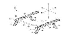
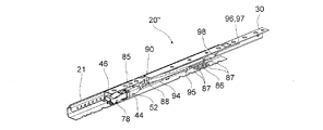
図示を省略した自動車(車両)の車内床面にはスライドレール装置10が設けてあり、スライドレール装置10(アッパレール30)の上面にはシート(図示略)が固定してある。
Hereinafter, an embodiment of the present invention will be described with reference to the accompanying drawings. The direction in the following description is based on the arrow direction indicated in the figure.
A
次にスライドレール装置10の詳しい構造について説明する。
スライドレール装置10は大きな構成要素として、左右一対のレールユニット20と、左右のレールユニット20の前端部同士を接続するループハンドル60と、を具備している。左右のレールユニット20は互いに左右対称であり、かつループハンドル60が左右対称形状なので、スライドレール装置10は全体として左右対称である。
左右のレールユニット20は以下の構造である。
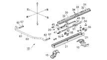
レールユニット20は車内床面に対して前後一対の固定ブラケット15を介して固定したロアレール21を有している。ロアレール21は前後方向に延びかつ上面が開口した金属製のチャンネル材であり、略水平な底壁22と、底壁22の左右両側部から上方に延びる左右一対の外壁部23と、左右の外壁部23の上縁部から内側に延びる左右一対の天井部24と、左右の天井部24の内側縁部から下方に延びる左右一対の内壁部(縦壁)25と、を具備している。図5等に示すように、左右の内壁部25の上縁部(天井部24に接続する部分)は前後方向に延びる基端支持部26となっている。左右の内壁部25の下縁部には、その上端部が基端支持部26に接続する多数のロック歯27(ロック機構)が前後方向に等間隔で並べて形成してあり、隣り合うロック歯27の間に下端が開放したロック溝28(ロック機構)が形成してある。
Next, the detailed structure of the
The
The left and
The
レールユニット20は、ロアレール21に対して前後方向にスライド可能なアッパレール30を有している。アッパレール30は前後方向に延びかつ下面が開口した金属製のチャンネル材であり、断面形状が略下向きコ字形をなす基部31と、基部31の左右両側壁の下縁部の長手方向の中央部を除く部分から上方に延びる立上り壁32と、該中央部から上方に延びる被ロック壁33と、を具備している。図2、図3、図5、図9等に示すように、左右の被ロック壁33の下縁部と基部31の側壁部の下縁部とに跨る部分には4つの前後動規制溝34が上向きに形成してあり、さらに基部31の側壁部の下縁部には前後動規制溝34の下端より下方まで延びる下向きの規制片35が一体的に突設してある。さらに図6、図7等に示すように、基部31の天井部の中央部近傍には下方に向かった後に後方に延びる係止片36が切り起こしにより形成してあり、基部31の左右側壁の中央部よりやや前側に位置する部分には内向きの係止片37がそれぞれ切り起こしにより形成してある。さらに基部31の前端近傍部には、左右側壁の下縁から内向きに延びる略水平な下側支持部38(バネ支持部)が一体的に突設してある。
The
レールユニット20はさらにアッパレール30に装着したロック解除レバー40(ロック操作レバー)とロックバネ50と付勢バネ70を具備している。
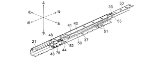
ロック解除レバー40は金属板をプレス成形した前後方向に延びかつ下面が開口した金属製のチャンネル材であり、左右一対の側壁41を具備している。図2、図5、図10、図11等に示すようにロック解除レバー40の上面には左右方向に延びる回転接触凸部42(回転支持手段)が突設してある。またロック解除レバー40の後端部には左右一対の略水平なバネ押圧片43がそれぞれ突設してあり、左右の側壁41の前部(回転接触凸部42より前方に位置する部分)の下縁部には上向きのバネ掛け溝44が凹設してある。図12等に示すように、ロック解除レバー40の前端近傍の上面には天井孔45が形成してあり、前端上部には左右の側壁41の前端同士を接続する上側支持部46が設けてある。さらに左右の側壁41の前端近傍の下縁部にはバネ掛け凹部47(第一係止部)が凹設してあり、左右の側壁41の前端下縁部には内向き略水平の下面支持片48(前側バネ支持部)が突設してある。
付勢バネ70は金属板をプレス成形した左右対称な板バネである。付勢バネ70は平板状の底面支持部71と、底面支持部71の後端から後方に延びた後に前斜め上方に延びさらに前斜め下方に向かう上面押圧片72と、底面支持部71の前縁から前斜め上方に延び先端が前斜め下方に屈曲する底面押圧片76と、底面支持部71の前縁から前方に向かって延びる左右一対の側部アーム77と、を具備している。上面押圧片72の後端部は側面視略横向きV字形の挿入端部73を構成しており、上面押圧片72の前端部には左右一対の下向係止片75を備えるハンドル押圧部74が形成してある。さらに上面押圧片72の左右方向に延びる線状の基端部72a(底面支持部71との接続部。バネ支持部側接触部)の直後に位置する部位は、基端部72aより一段上方に位置しかつ断面形状が略円弧状をなす左右方向に延びる屈曲段部72b(ハンドル側接触部)となっている。また左右の側部アーム77の前端近傍には上向きの上向係止片78(第一係合部)が突設してある。さらに左右の側部アーム77の長手方向の中間部には断面形状が略円弧状をなす中間屈曲部77aが形成してある。側部アーム77の中間屈曲部77aより前方に位置する部分は、中間屈曲部77aより後方に位置する部分(の前方への延長方向)に対して僅かに下方に傾斜している。
付勢バネ70は、ロック解除レバー40の前端開口(上側支持部46と下面支持片48の間)からロック解除レバー40の前端部の内部空間(天井孔45の直下に位置する空間)に挿入してある。付勢バネ70を挿入すると、上向係止片78がロック解除レバー40の左右のバネ掛け凹部47に対して下方から係合するので、付勢バネ70は前後方向に移動規制された状態でロック解除レバー40と一体化する。
ロックバネ50(回転支持手段)は金属製の線材を曲折加工した左右対称な部材である。ロックバネ50の左右両側部の長手方向の中央部よりやや後方に位置する部分には外側に向かって略水平に延びる前後一対のロック部51(ロック機構)が形成してある。ロック部51より後方に位置する部分(ただし後端部を除く)は自由状態において略水平であり、ロック部51より前方に位置する部分(ただし前端部を除く)は自由状態において略水平である。ロックバネ50の前端には左右一対の前端係止片52が外向き略水平に突設してあり、ロックバネ50の後端部は側面視で上向きに傾斜する後端係止部53を構成している。
ロック解除レバー40(及び付勢バネ70)は、その後端部をアッパレール30の前端開口部(基部31の前端部と下側支持部38の間)からアッパレール30の内部空間の前端部に挿入した後に、全体をアッパレール30に対して後方にスライドさせることにより、略全体をアッパレール30内に収納してある(図15、図16に示すように上側支持部46の前端部のみがアッパレール30の前方に突出している)。このようにしてロック解除レバー40の略全体をアッパレール30内に収納すると、回転接触凸部42が基部31の天井面に接触し(図10、図11の接触部P参照。ロック解除レバー40の上面における回転接触凸部42以外の部分と基部31の天井面の間には空間が形成されている)、かつ、付勢バネ70の底面支持部71の直下に左右の下側支持部38が位置するので、上向係止片78のバネ掛け凹部47からの下方への脱落(付勢バネ70のロック解除レバー40からの下方への脱落)が規制される。図6〜図8、図10、及び、図11に示すようにロックバネ50は、後端係止部53を係止片36に係止し(図10の三角印を参照)、左右両側部のロック部51よりやや前側に位置する部分を左右の係止片37にそれぞれ係止し(図10の三角印を参照)、各ロック部51を対応する前後動規制溝34に下方から係合し、さらに左右の前端係止片52を下方からバネ掛け溝44に係止してあり、ロックバネ50の一対のロック部51の間に位置する部分の上面にバネ押圧片43が上方から当接している。このようにしてロックバネ50をアッパレール30及びロック解除レバー40に取り付けると、ロックバネ50はアッパレール30に対して、ロックバネ50の後端係止部53と係止片36の係止が解除されず、かつ、前端係止片52がバネ掛け溝44との係止を維持する微小範囲内で前後方向に移動可能となる。またロックバネ50は弾性変形することにより上向きの付勢力(弾性力)を発生するため(図10の↑印を参照)、この付勢力によってロック解除レバー40の回転接触凸部42が基部31の天井部に押しつけられ、ロック解除レバー40は天井部と回転接触凸部42の接触部Pを中心にして回転接触凸部42回りに(左右方向の仮想回転軸回りに)回転可能となり、ロック解除レバー40の前端部に上向きの外力を掛けないときロック解除レバー40は図10、図15に示すロック位置に保持される。一方、ロックバネ50の付勢力に抗してロック解除レバー40の前端部に上向きの外力を掛けるとロック解除レバー40は図11、図16に示すアンロック位置まで回転する。すると、図16、図21に示すようにロック解除レバー40のバネ押圧片43が一対のロック部51の間に位置する部分を下方に押し下げるので、各ロック部51が対応するロック溝28から下方に脱出する(図9に仮想線で描かれたロック部51を参照)。
The
The
The urging
The biasing
The lock spring 50 (rotation support means) is a bilaterally symmetric member obtained by bending a metal wire. A pair of front and rear locking portions 51 (locking mechanisms) extending substantially horizontally toward the outside are formed in a portion located slightly rearward from the central portion in the longitudinal direction of the left and right side portions of the
The lock release lever 40 (and the urging spring 70) has its rear end inserted into the front end of the inner space of the
このようにして一体化したアッパレール30、ロック解除レバー40、ロックバネ50、及び、付勢バネ70を、ロアレール21の前端開口又は後端開口からロアレール21の内部に挿入することによりアッセンブリしたものがレールユニット20である。レールユニット20をアッセンブリすると図4に示すように、アッパレール30の立上り壁32及び被ロック壁33が外壁部23と内壁部25の間に形成された空間に入り込み(図4では被ロック壁33の図示は省略)、さらに当該空間に配設したリテーナ55に回転可能に支持された複数のベアリングボール56が立上り壁32の外面と外壁部23の内面にそれぞれ回転可能に接触するので、アッパレール30(及びロック解除レバー40、ロックバネ50)はロアレール21に対して前後方向にスライド可能となる。さらにアッパレール30とロアレール21の間には図示を省略した前端ストッパ手段と後端ストッパ手段が設けてあるので、アッパレール30はロアレール21に対して前端位置(図示略)と後端位置(図1の位置)の間をスライド可能である。
またロック解除レバー40がロック位置に位置するときは、図8、及び、図9の実線で示すように各ロック部51が対応する前後動規制溝34及びロック溝28に下方から係合するので、アッパレール30のロアレール21に対するスライドは規制される。一方、ロック解除レバー40をアンロック位置まで下方に回転させると、図9の仮想線で示すように各ロック部51が係合していたロック溝28から下方に脱出するので、アッパレール30はロアレール21に対してスライド可能となる。
アッセンブリされた左右一対のレールユニット20は、互いを平行にしかつ互いの前後位置を合わせた上で(アッパレール30のロアレール21に対するスライド位置も一致させる)、アッパレール30の上面にシート(図示略)の座部が固定される。
A rail assembled by inserting the
When the
The paired left and
このようにして左右のレールユニット20とシート11を一体化したら、左右のロック解除レバー40に対して左右一対の付勢バネ70を利用してループハンドル(ハンドル)60を接続する。
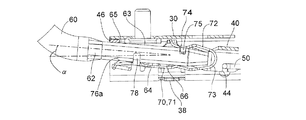
ループハンドル60は金属製のパイプ材を曲げ加工したものであり、左右方向に延びる操作部61と、操作部61の左右両端部から後斜め下方に向かって延びる一対の傾斜部と、各傾斜部の左右両端部からそれぞれ後方に向かって延びる一対の後端接続部62と、を具備している。後端接続部62の上側当接面63及び下側当接面64は互いに平行(水平)な平面であり、上側当接面63の前部は上側被支持部65を構成しており、下側当接面64の後部は下側被支持部66を構成している。さらに上側当接面63の後端近傍には左右方向に延びる係止溝67が形成してある。
ループハンドル60は、左右の後端接続部62をロック解除レバー40の前端部の内部空間に対して前方から挿入することにより、ロック解除レバー40に対して接続する。後端接続部62を挿入すると、後端接続部62は底面支持部71と上面押圧片72(ハンドル押圧部74)の間の空間に進入し、下側当接面64に底面支持部71が接触し、左右の下向係止片75(第二係合部)が係止溝67(第二係止部)に嵌合し、かつハンドル押圧部74が上側当接面63の後端近傍部(係止溝67の周片部)に当接する。後端接続部62をロック解除レバー40の前端部の内部空間に挿入する前の時点では付勢バネ70は自由状態にあり、この状態においては底面支持部71とハンドル押圧部74の間の上下間隔は後端接続部62の上下寸法より狭いので、後端接続部62を底面支持部71と上面押圧片72(ハンドル押圧部74)の間の空間に挿入すると上面押圧片72が上側に弾性変形し、底面支持部71とハンドル押圧部74から下側当接面64と上側当接面63に対してそれぞれ押圧力が及ぶ。また図15に示すように左右の側部アーム77の先端部77b(下側支持部)の下縁部が左右の下面支持片48の上面の後縁部より前方部分に接触し、左右の中間屈曲部77aが下面支持片48から上方に離間する。さらに下方に弾性変形した底面押圧片76の前端近傍に形成した屈曲部76a(上向き押圧部)が下側当接面64の前部に当接する。すると付勢バネ70を介して左右の後端接続部62とロック解除レバー40の前端部が一体化し、後端接続部62はロック解除レバー40に対して実質的に前後方向への相対移動が規制される。
このようにループハンドル60を左右のレールユニット20と一体化することによりスライドシート装置10をアッセンブリすると、後端接続部62が常に底面押圧片76(屈曲部76a)から上向きの付勢力を受けさらに常に上面押圧片72(ハンドル押圧部74)から下向きの付勢力を受けるので、上側被支持部65が上側支持部46に対して常に(左右方向の軸回りに回転可能に)接触し、さらに下側被支持部66が屈曲段部72bと常に接触し、かつ基端部72aが下側支持部38に対して常に(基端部72aと下側支持部38の上面の左右方向に延びる接触部回りに回転可能に)接触する。
When the left and
The loop handle 60 is obtained by bending a metal pipe material, and includes an
The loop handle 60 is connected to the
When the
以上説明したようにスライドレール装置10は、上向係止片78をロック解除レバー40のバネ掛け凹部47に対して係合するだけで、付勢バネ70をロック解除レバー40の内部空間に前後方向への相対移動を規制した状態で簡単に取り付けることができ、ループハンドル60の後端部をロック解除レバー40の内部空間に挿入することによりループハンドル60の後端部を付勢バネ70によって支持できる。そのためスライドレール装置10の組立作業を迅速に行うことが可能である。
しかもロック解除レバー40と付勢バネ70の一体物をアッパレール30の内部空間に挿入した後にロックバネ50を利用してアッパレール30とロック解除レバー40を一体化すると、底面支持部71の直下に下側支持部38が位置するので、下側支持部38によって付勢バネ70がロック解除レバー40の下面開口から下方に脱落するのを防止できる。
As described above, the
In addition, when the
アッセンブリしたスライドシート装置10は、左右のロアレール21に固定した固定ブラケット15を車内床面に固定することにより車内床面に取り付ける。
The assembled
続いてスライドレール装置10の動作について説明する。
乗客が手で操作部61を掴んでループハンドル60全体を上方に回転させると、この回転力が後端接続部62からロック解除レバー40の前端部に伝わりロック解除レバー40が後端接続部62と一緒に上方に回転する。するとロック位置に位置していたロック解除レバー40がアンロック位置まで回転するので、ロアレール21に対するスライドが規制されていたアッパレール30がロアレール21に対してスライド可能となる。
このときの後端接続部62(ループハンドル60)、ロック解除レバー40、及び、付勢バネ70の動作の詳細は以下の通りである。
図10及び図15に示すようにループハンドル60に対して乗客が力を加えないとき(ロック解除レバー40がロック位置に位置するとき)、上側被支持部65が上側支持部46に対して面接触し、かつ、下側被支持部66に対して屈曲段部72bが接触している付勢バネ70の底面支持部71が下側支持部38に対してそれぞれ面接触するので、後端接続部62は自身の軸線がロック解除レバー40の前端部の軸線と一致する位置に保持される。この状態からループハンドル60を上方に回転させると、左右の後端接続部62は上側被支持部65と上側支持部46の接触部、及び、基端部72aと下側支持部38の接触部を中心にアッパレール30に対して相対回転し、さらに上側被支持部65によって上側支持部46が上方に押圧されたロック解除レバー40の後部が回転接触凸部42(P)を中心に下方に回転する(図11及び図16参照)。ここでループハンドル60に対して乗客が力を加えないときの点A(バネ押圧片43のロック部51に対する作用位置)から点B(回転接触凸部42の位置、即ちロック解除レバー40の回転中心位置)までの前後方向距離をL1、点Bから点C(上側支持部46)までの前後方向距離をL2、点Cから点D(下側支持部38)までの前後方向距離をL3、点Cから点E(操作部61)までの前後方向距離をL4とし、ロック解除レバー40をアンロック位置まで移動させる(ロック部51をロック溝28から下方に脱出させる)ときにバネ押圧片43がロックバネ50に及ぼす下向きの移動力をFとすると、乗客が操作部61を上向きに持ち上げる力F1は、F1=F×L1/L2×L3/L4
となる。
一方、図17に示す比較例のように後端接続部62がロック解除レバー40と同軸状態で回転する構造(後端接続部62をロック解除レバー40に対して固定した構造)の場合、乗客が操作部61を上向きに持ち上げる力F2は、
F2=F×L1/(L2+L4)
となる。
本実施形態ではL1=125.7mm、L2=96.0mm、L3=36.5mm、L4=115.1mmに設定してあるので、
F1=0.42F
F2=0.60F
となり、乗客は図17の比較例の場合に比べてより小さい力でロック解除を行うことができる。
Next, the operation of the
When the passenger grasps the
Details of the operations of the rear end connecting portion 62 (loop handle 60), the
When the passenger does not apply force to the loop handle 60 as shown in FIGS. 10 and 15 (when the unlocking
It becomes.
On the other hand, in the case of a structure in which the rear
F2 = F × L1 / (L2 + L4)
It becomes.
In this embodiment, L1 = 125.7 mm, L2 = 96.0 mm, L3 = 36.5 mm, and L4 = 15.1 mm are set.
F1 = 0.42F
F2 = 0.60F
Thus, the passenger can release the lock with a smaller force than in the comparative example of FIG.
さらに点Dが点Bより前方に位置するのであればL1〜L4をどのような寸法とした場合であってもループハンドル60(操作部61)のアッパレール30に対する上方への回転角βは、ロック解除レバー40のアッパレール30に対する回転角αより大きくなる(図17の比較例の場合はループハンドル60の回転角もα)。従って、乗客がある程度大きな回転角だけ操作部61を上方に回転させないとロック解除されることがないので、乗客に対して快適な操作感を与えることが可能である。
また図示したようにロック解除レバー40はアッパレール30の内部空間に配設してあるので、ロック解除レバー40の上下方向の回転可能範囲は狭い範囲に制限されている。しかし、ロック解除を行う際のロック解除レバー40の上方への回転角(α)はループハンドル60の上方への回転角(β)より小さくなるので、ロック解除レバー40をアッパレール30の内面に接触させることなくロック解除を確実に行うことが可能である。
Further, if the point D is positioned ahead of the point B, the upward rotation angle β of the loop handle 60 (the operation unit 61) with respect to the
Further, as shown in the figure, the
さらにループハンドル60が上下に回転するとき(ロック解除レバー40がロック位置とアンロック位置の間を回転するとき)は、付勢バネ70の基端部72aが下側支持部38に対して常に(基端部72aと下側支持部38の間の左右方向に延びる接触部回りに回転可能に)接触し、かつ、屈曲段部72bが下側被支持部66に対して常に(屈曲段部72bと下側被支持部66の間の左右方向に延びる接触部回りに回転可能に)接触するので、付勢バネ70の下側支持部38及びループハンドル60に対する接触位置が不変である。そのため乗客がループハンドル60を回転操作するときの操作力にばらつきが生じにくく、乗客は毎回同じ大きさの力でループハンドル60を回転操作できる。
Further, when the loop handle 60 rotates up and down (when the
さらにループハンドル60を図15の位置から図16の位置まで回転させるときに乗客は小さい力でループハンドル60を回転操作することが可能である。
即ち、図18(a1)に示すようにループハンドル60が図15の位置にあるとき(ロック状態のとき)、本実施形態のスライドレール装置10の基端部72aと先端部77bの前後方向の直線距離はL1、底面押圧片76と側部アーム77のなす角度はθ1である。また図18(a2)に示すようにループハンドル60を図16の位置まで上方に回転させると(アンロック状態にすると)、下面支持片48が図15の状態から距離Hだけ上昇し、底面押圧片76と側部アーム77のなす角度はθ1’となる(基端部72aと先端部77bの前後方向の直線距離はL1より僅かに短くなるが、L1との差は無視できるほど小さいので、便宜上L1とする)。本実施形態の側部アーム77には中間屈曲部77aを形成してあるので、ループハンドル60が図15の位置から図16の位置まで回転するとき、側部アーム77の先端部77bより後方に位置する部分は下面支持片48とは接触せず、θ1とθ1’との差は非常に小さい値となる。
一方、図18(b1)に示すように、側部アーム77に中間屈曲部77aを形成しない比較例の場合は、ループハンドル60が図15の位置にあるとき(ロック状態のとき)、下面支持片48の後端部(と側部アーム77の接触点)と基端部72aの前後方向の直線距離はL2、底面押圧片76と側部アーム77のなす角度はθ2となる。また図18(b2)に示すように、ループハンドル60を図16の位置まで上方に回転させると(アンロック状態にすると)、下面支持片48が図15の状態から距離Hだけ上昇し、下面支持片48の後端部と側部アーム77の下面が接触し、側部アーム77の下面支持片48の後端部より前方に位置する部分は下面支持片48から上方に離間する。そして底面押圧片76と側部アーム77のなす角度はθ2’となる(下面支持片48の後端部(と側部アーム77の接触点)と基端部72aの前後方向の直線距離はL2より僅かに短くなるが、L2との差は無視できるほど小さいので、便宜上L2とする)。このときのθ2とθ2’の差は、θ1とθ1’との上記差より大きい値となる。
即ち、ループハンドル60を図15の位置から図16の位置まで回転させるためには、側部アーム77を(a1)(b1)の状態から(a2)(b2)の状態になるまで弾性変形させる必要があるが、L1がL2より長いため(θ2とθ2’の差が、θ1とθ1’との差より大きいため)、本実施形態のスライドレール装置10の側部アーム77は比較例の側部アーム77より小さい力で距離H分だけ弾性変形する。それ故、乗客は本実施形態のスライドレール装置10のループハンドル60を図15の位置から図16の位置まで小さい力で回転操作することが可能である。
Further, when the loop handle 60 is rotated from the position of FIG. 15 to the position of FIG. 16, the passenger can rotate the loop handle 60 with a small force.
That is, when the loop handle 60 is in the position shown in FIG. 15 (when locked) as shown in FIG. 18A1, the longitudinal direction of the
On the other hand, as shown in FIG. 18 (b1), in the case of the comparative example in which the intermediate
That is, in order to rotate the loop handle 60 from the position of FIG. 15 to the position of FIG. 16, the
続いて本発明の第2の実施形態について図19〜図23を参照しながら説明する。なお従前の実施形態と同じ部材には同じ符号を付すに止めて、その詳細な説明は省略する。
本実施形態のレールユニット20’’はロック解除レバー40の代わりにロックレバー85(ロック操作レバー)を具備している。ロックレバー85の基本構造はロック解除レバー40と同じであり、側壁41、バネ掛け溝44、天井孔45、上側支持部46、バネ掛け凹部47、下面支持片48を具備しており、その前端部にループハンドル60が接続している。その一方で後端部には水平板状のロック板86を左右一対として具備している。図示するようにロック板86には3つの方形孔が貫通孔として形成してあり、各方形孔の前後には前後方向に等間隔で並ぶ4つのロック部87(ロック機構)が形成してある。さらにロックレバー85の前部には左右方向に延びる円柱形状の被支持部88(回転支持手段)が左右一対として突設してある。
アッパレール30の基部31の天井部には切り起こしにより左右一対の回転支持片90が下向きに突設してある。図20、図21に示すように回転支持片90の下縁部には上方に向かって延びるV字溝91(回転支持手段)が形成してある。図示するようにV字溝91の前面と後面を構成する一対の支持面92は前後対称であり、上方に向かうについて互いの前後間隔が徐々に狭くなっている。そして左右の回転支持片90のV字溝91に対してロックレバー85の左右の被支持部88を下方からそれぞれ係合させてある。さらに左右のロック板86の各ロック部87を左右の前後動規制溝34に下方から係合させてある。図示は省略してあるが、ロック板86の各ロック部87はロアレール21のロック溝28に対して下方から係脱可能である。
さらにレールユニット20’’はロックバネ50の代わりとして、金属製の線材からなる左右一対の前側付勢バネ94(ロック付勢手段)を具備している。左右の前側付勢バネ94は互いに左右対称であり、前端部にはバネ掛け溝44に係合する前端係止片52を具備しており、後端部にはアッパレール30の基部31の左右の側壁にそれぞれ形成した貫通支持孔(図示略)にそれぞれ嵌合する前端係止片52と同じ形状の後端係止片95が突設してある。さらに左右の前側付勢バネ94の中間部が中間係止片80(と基部31の側壁の間)に上方から係止しているので、左右の前端係止片52からロックレバー85(バネ掛け溝44)に対して上向きの付勢力が及んでいる。従って、この上向きの付勢力(係合補助付勢力)によって左右の被支持部88がV字溝91内を上方に移動し、被支持部88が所定の上下位置に達したときに、被支持部88の前後二カ所が前後の支持面92の双方に接触し、該付勢力によってこの接触状態が維持されるので、ロックレバー85はアッパレール30に対して前後方向にがたつくことなく被支持部88回りに回転可能である。
またアッパレール30の基部31の天井面の後部には金属製の後側付勢バネ96(ロック付勢手段)の後部を構成する基部97が固定してある。基部97からは弾性変形部98が前方に向かって延びており、弾性変形部98の上面はロックレバー85の後端部を常に上方に付勢しているので、ロック板86の各ロック部87と前後動規制溝34の係合状態は常に維持される。さらに前側付勢バネ94と弾性変形部98がロックレバー85に及ぼす上向きの付勢力によってロックレバー85の被支持部88と回転支持片90のV字溝91の係合状態が維持されるので、ロックレバー85は被支持部88を中心にアッパレール30に対して回転可能である。さらに弾性変形部98の付勢力が前側付勢バネ94の付勢力より大きいので、ループハンドル60に対して操作力を与えないときロックレバー85は各ロック部87が対応するロック溝28に係合するロック位置(図20の位置)に位置する。その一方で、乗客が弾性変形部98(及び前側付勢バネ94)の付勢力に抗してループハンドル60を上方に持ち上げると、ロックレバー85は各ロック部87が対応するロック溝28から下方に脱出するアンロック位置(図示略)まで回転する。
この場合は図20に示すように点Aがロックレバー85と弾性変形部98の作用位置となり、点Bが被支持部88の位置となる。そしてこの場合もF1がF2より小さくなる(ように)L1、L2、L3、L4を設定している。
Next, a second embodiment of the present invention will be described with reference to FIGS. It should be noted that the same members as those in the previous embodiment are designated by the same reference numerals, and detailed description thereof is omitted.
The
A pair of left and right
Furthermore, the
A base 97 constituting the rear part of a metal rear biasing spring 96 (lock biasing means) is fixed to the rear part of the ceiling surface of the
In this case, as shown in FIG. 20, the point A becomes the operating position of the
10 スライドレール装置
15 固定ブラケット
20 20’’ レールユニット
21 ロアレール
22 底壁
23 外壁部
24 天井壁
25 内壁部(縦壁)
26 基端支持部
27 ロック歯(ロック機構)
28 ロック溝(ロック機構)
30 アッパレール
31 基部
32 立上り壁
33 被ロック壁
34 前後動規制溝
35 規制片
36 37 係止片
38 下側支持部(バネ支持部)
40 ロック解除レバー(ロック操作レバー)
41 側壁
42 回転接触凸部(回転支持手段)
43 バネ押圧片
44 バネ掛け溝
45 天井孔
46 上側支持部
47 バネ掛け凹部(第一係止部)
48 下面支持片(前側バネ支持部)
50 ロックバネ(回転支持手段)
51 ロック部(ロック機構)
52 前端係止片
53 後端係止部
55 リテーナ
56 ベアリングボール
60 ループハンドル(ハンドル)
61 操作部
62 後端接続部
63 上側当接面
64 下側当接面
65 上側被支持部
66 下側被支持部
67 係止溝(第二係止部)
70 付勢バネ
71 底面支持部
72 上面押圧片
72a 基端部(バネ支持部側接触部)
72b 屈曲段部(ハンドル側接触部)
73 挿入端部
74 ハンドル押圧部
75 下向係止片(第二係合部)
76 底面押圧片
76a 屈曲部(上向き押圧部)
77 側部アーム
77a 中間屈曲部
77b 先端部(下側支持部)
78 上向係止片(第一係合部)
85 ロックレバー(ロック操作レバー)
86 ロック板
87 ロック部(ロック機構)
88 被支持部(回転支持手段)
90 回転支持片
91 V字溝(回転支持手段)
92 支持面
94 前側付勢バネ
95 後端係止片
96 後側付勢バネ
97 基部
98 弾性変形部
P 接触部
DESCRIPTION OF
26 Base
28 Lock groove (lock mechanism)
30
40 Unlocking lever (locking lever)
41
43
48 Bottom support piece (front spring support)
50 Lock spring (rotation support means)
51 Locking part (locking mechanism)
52 Front
61
70 Biasing spring 71
72b Bent step (handle side contact part)
73
76
77
78 Upward locking piece (first engaging part)
85 Lock lever (lock operation lever)
88 Supported parts (rotating support means)
90 rotation support piece 91 V-shaped groove (rotation support means)
92
Claims (4)
シートを支持すると共に上記ロアレールに前後方向にスライド可能として支持したアッパレールと、
上記アッパレールとロアレールの間に設けた、アッパレールのスライドを規制又は規制解除するロック機構と、
上記アッパレールの内部空間に挿入した、前面及び下面が開口し、かつ下縁部に第一係止部を有するロック操作レバーと、
該ロック操作レバーが上記内部空間の所定位置に位置するときに、該ロック操作レバーを上記アッパレールに対して、該ロック機構によるスライド規制を許容するロック位置と前部が該ロック位置に比べて上方に移動して該スライド規制を解除するアンロック位置とに上下回転可能として支持する回転支持手段と、
自身の後端部を上記ロック操作レバーの内部空間に挿入し、かつ自身の前端部が上記ロック操作レバーの前面開口から前方に突出するハンドルと、
上記第一係止部に対して前後動を規制可能に係合する第一係合部を備え、上記ロック操作レバーの上記内部空間において上記ハンドルの上記後端部を前後方向への相対移動を規制しながら支持する付勢バネと、
上記アッパレールに設けた、上記回転支持手段が上記ロック操作レバーを支持したときに、上記付勢バネの直下に位置して該付勢バネが上記ロック操作レバーの下面開口から下方に脱落するのを規制するバネ支持部と、
を備え、
上記付勢バネが、
上記ハンドルの直下に位置しかつ上記バネ支持部に対して上方から接触するバネ支持部側接触部と、
上記ハンドルの直下に位置しかつ該バネ支持部側接触部から上方及び前後方向に離間した位置において上記ハンドルの下面に対して下方から接触するハンドル側接触部と、
を備えることを特徴とする車両用スライドレール装置。 A lower rail extending in the front-rear direction and immovable relative to the vehicle floor,
An upper rail that supports the seat and is slidable in the front-rear direction on the lower rail;
A locking mechanism provided between the upper rail and the lower rail for restricting or releasing the slide of the upper rail;
A lock operating lever inserted into the inner space of the upper rail, having a front surface and a lower surface opened, and having a first locking portion at a lower edge portion;
When the lock operation lever is located at a predetermined position in the internal space, the lock operation lever is allowed to be slid relative to the upper rail. A rotation support means for supporting the upper and lower rotation at an unlock position where the slide restriction is released.
A handle whose own rear end is inserted into the internal space of the lock operation lever, and whose front end projects forward from the front opening of the lock operation lever;
Comprising a first engagement portion engaged to be restricting the movement back and forth relative to the first locking portion, the relative movement in the longitudinal direction the rear end portion of the handle in the internal space of the locking lever An urging spring to support while regulating,
When the rotation support means provided on the upper rail supports the lock operating lever, the biasing spring is positioned immediately below the biasing spring and drops downward from the lower surface opening of the lock operating lever. A spring support to regulate,
With
The biasing spring is
A spring support portion-side contact portion that is located directly below the handle and contacts the spring support portion from above;
A handle side contact portion that is located directly below the handle and contacts the lower surface of the handle from below at a position spaced apart from the spring support portion side contact portion in the upward and front-rear direction;
The vehicle slide rail device according to claim Rukoto equipped with.
上記バネ支持部側接触部が、上記バネ支持部に対して常に回転可能に接触し、
上記ハンドル側接触部が、上記ハンドルの下面に対して常に回転可能に接触する車両用スライドレール装置。 The vehicle slide rail device according to claim 1,
The spring support portion side contact portion is always in contact with the spring support portion so as to be rotatable ,
The vehicle slide rail device in which the handle side contact portion is always in contact with the lower surface of the handle so as to be rotatable.
上記ロック操作レバーに上側支持部、及び、上記バネ支持部より前方に位置し、該ロック操作レバーが上記ロック位置からアンロック位置に回転したときに該ロック操作レバーと一緒に上方に移動する前側バネ支持部を形成し、
上記ハンドルの後端より前方に位置する部分に、上記上側支持部に対して下方から上下方向に回転可能に接触する上側被支持部を形成し、
上記付勢バネが、
上記バネ支持部側接触部より前方に位置し、かつ上記ハンドルの底面を上向きに付勢する上向き押圧部と、
上記前側バネ支持部の上面の後端位置より前方部分に対して常に接触し、上記付勢バネの自身と上記バネ支持部側接触部との間に位置する部位を上記前側バネ支持部から常に離間させる下側支持部と、
を備える車両用スライドレール装置。 The vehicle slide rail device according to claim 2,
The front side of the lock operation lever that is positioned in front of the upper support portion and the spring support portion and moves upward together with the lock operation lever when the lock operation lever rotates from the lock position to the unlock position. Forming a spring support,
An upper supported portion that is rotatably contacted with the upper support portion in the vertical direction from below is formed in a portion located in front of the rear end of the handle,
The biasing spring is
An upward pressing portion that is positioned in front of the spring support portion side contact portion and biases the bottom surface of the handle upward;
The portion that is always in contact with the front portion from the rear end position of the upper surface of the front spring support portion and is located between the biasing spring itself and the spring support portion side contact portion is always located from the front spring support portion. A lower support to be spaced apart;
A vehicle slide rail device comprising:
上記第一係合部が上記第一係止部に対してのみ係合し、 The first engaging portion engages only with the first locking portion,
上記ハンドルが第二係止部を備え、 The handle includes a second locking portion;
上記付勢バネが、上記第二係止部に対してのみ前後動を規制可能に係合する第二係合部を備え、 The urging spring includes a second engagement portion that engages with the second locking portion so as to be able to restrict the back-and-forth movement only,
上記第二係合部が上記第一係合部より後方に位置する車両用スライドレール装置。 A vehicle slide rail device in which the second engagement portion is located behind the first engagement portion.
Priority Applications (3)
| Application Number | Priority Date | Filing Date | Title |
|---|---|---|---|
| JP2012030045A JP5734890B2 (en) | 2012-02-15 | 2012-02-15 | Slide rail device for vehicle |
| US13/758,403 US9073455B2 (en) | 2012-02-15 | 2013-02-04 | Slide rail device for vehicle |
| CN201310047453.5A CN103253158B (en) | 2012-02-15 | 2013-02-06 | Railroad for vehicle |
Applications Claiming Priority (1)
| Application Number | Priority Date | Filing Date | Title |
|---|---|---|---|
| JP2012030045A JP5734890B2 (en) | 2012-02-15 | 2012-02-15 | Slide rail device for vehicle |
Publications (3)
| Publication Number | Publication Date |
|---|---|
| JP2013166434A JP2013166434A (en) | 2013-08-29 |
| JP2013166434A5 JP2013166434A5 (en) | 2014-09-25 |
| JP5734890B2 true JP5734890B2 (en) | 2015-06-17 |
Family
ID=48944828
Family Applications (1)
| Application Number | Title | Priority Date | Filing Date |
|---|---|---|---|
| JP2012030045A Active JP5734890B2 (en) | 2012-02-15 | 2012-02-15 | Slide rail device for vehicle |
Country Status (3)
| Country | Link |
|---|---|
| US (1) | US9073455B2 (en) |
| JP (1) | JP5734890B2 (en) |
| CN (1) | CN103253158B (en) |
Families Citing this family (17)
| Publication number | Priority date | Publication date | Assignee | Title |
|---|---|---|---|---|
| US7455343B2 (en) * | 2005-09-12 | 2008-11-25 | Ts Tech Co., Ltd. | Passenger's weight measurement device for vehicle seat and attachment structure for load sensor |
| JP5632727B2 (en) * | 2010-12-13 | 2014-11-26 | シロキ工業株式会社 | Slide rail device for vehicle |
| JP5613744B2 (en) * | 2012-10-24 | 2014-10-29 | シロキ工業株式会社 | Slide rail device for vehicle |
| JP6236655B2 (en) * | 2014-04-25 | 2017-11-29 | トヨタ紡織株式会社 | Vehicle seat |
| CN104553894B (en) * | 2014-12-31 | 2017-05-10 | 重庆延锋安道拓汽车部件系统有限公司 | Automobile seat slide rail |
| FR3032657B1 (en) * | 2015-02-17 | 2018-11-16 | Faurecia Sieges D'automobile | SLIDE FOR VEHICLE SEAT AND VEHICLE SEAT COMPRISING SUCH A SLIDER |
| EP3253614A4 (en) | 2015-06-04 | 2018-09-19 | Milsco Manufacturing Company | Modular forward and rearward seat position adjustment system, with integral vibration isolation system |
| TWI568382B (en) * | 2016-01-22 | 2017-02-01 | 川湖科技股份有限公司 | Slide rail assembly and operation method thereof |
| DE102017208725A1 (en) | 2016-05-26 | 2017-11-30 | Toyota Boshoku Kabushiki Kaisha | Sitzlängsverstellvorrichtung |
| JP6745080B2 (en) * | 2016-07-06 | 2020-08-26 | シロキ工業株式会社 | Vehicle slide rail device |
| JP2018002049A (en) * | 2016-07-06 | 2018-01-11 | シロキ工業株式会社 | Slide rail device for vehicle |
| CN109421554A (en) * | 2017-08-22 | 2019-03-05 | 重庆韩汽车座椅有限公司 | Vehicle seat used adjusting guide rail |
| US10695849B2 (en) * | 2018-02-19 | 2020-06-30 | Robert Bosch Gmbh | Table saw with two stage table extension system |
| DE102019206304B4 (en) * | 2018-05-04 | 2022-01-27 | Lear Corporation | RAIL ARRANGEMENT |
| IT201800005731A1 (en) * | 2018-05-25 | 2019-11-25 | Slider for a vehicle seat | |
| DE102019209038B4 (en) | 2019-06-21 | 2022-02-17 | Lear Corp. | SEAT RAIL MECHANISM |
| CN112224098B (en) * | 2020-10-19 | 2022-05-27 | 恺博(常熟)座椅机械部件有限公司 | Sliding rail with enhanced rigidity modulus |
Family Cites Families (12)
| Publication number | Priority date | Publication date | Assignee | Title |
|---|---|---|---|---|
| JP4253554B2 (en) * | 2003-09-30 | 2009-04-15 | 富士機工株式会社 | Vehicle seat slide device |
| JP4121862B2 (en) * | 2003-01-24 | 2008-07-23 | 岐阜車体工業株式会社 | Lock mechanism in vehicle seat track sliding device |
| JP2005238929A (en) * | 2004-02-25 | 2005-09-08 | Toyota Boshoku Corp | Locking device of seat slide adjuster |
| JP4355963B2 (en) * | 2007-01-30 | 2009-11-04 | 株式会社今仙電機製作所 | Slide rail device |
| JP2009241919A (en) * | 2007-11-15 | 2009-10-22 | Imasen Electric Ind Co Ltd | Seat sliding device |
| CN102046412B (en) * | 2008-05-29 | 2013-03-20 | 株式会社今仙电机制作所 | Seat sliding device |
| JP5347643B2 (en) * | 2008-10-15 | 2013-11-20 | アイシン精機株式会社 | Vehicle seat slide device |
| JP4947123B2 (en) * | 2009-11-04 | 2012-06-06 | アイシン精機株式会社 | Vehicle sliding device |
| JP5545835B2 (en) | 2010-04-28 | 2014-07-09 | シロキ工業株式会社 | Slide rail device for vehicle |
| JP5621724B2 (en) * | 2011-07-12 | 2014-11-12 | アイシン精機株式会社 | Vehicle seat slide device |
| JP5927970B2 (en) * | 2012-02-15 | 2016-06-01 | アイシン精機株式会社 | Vehicle seat slide device |
| JP5962250B2 (en) * | 2012-06-21 | 2016-08-03 | アイシン精機株式会社 | Vehicle seat slide device |
-
2012
- 2012-02-15 JP JP2012030045A patent/JP5734890B2/en active Active
-
2013
- 2013-02-04 US US13/758,403 patent/US9073455B2/en active Active
- 2013-02-06 CN CN201310047453.5A patent/CN103253158B/en not_active Expired - Fee Related
Also Published As
| Publication number | Publication date |
|---|---|
| CN103253158B (en) | 2016-07-20 |
| JP2013166434A (en) | 2013-08-29 |
| CN103253158A (en) | 2013-08-21 |
| US20130206950A1 (en) | 2013-08-15 |
| US9073455B2 (en) | 2015-07-07 |
Similar Documents
| Publication | Publication Date | Title |
|---|---|---|
| JP5734890B2 (en) | Slide rail device for vehicle | |
| JP5632727B2 (en) | Slide rail device for vehicle | |
| JP5647507B2 (en) | Slide rail device for vehicle | |
| JP5650180B2 (en) | Slide rail device for vehicle | |
| JP5545835B2 (en) | Slide rail device for vehicle | |
| JP5662070B2 (en) | Slide rail device for vehicle | |
| JP2013166434A5 (en) | ||
| WO2012032828A1 (en) | Slide rail device for vehicle | |
| WO2011136049A1 (en) | Slide rail device for vehicle | |
| WO2011136048A1 (en) | Slide rail device for vehicle | |
| JP2014037173A (en) | Vehicle slide rail device | |
| JP5613743B2 (en) | Slide rail device for vehicle | |
| JP2011245956A (en) | Seat slide device | |
| JP6745080B2 (en) | Vehicle slide rail device | |
| JP5647506B2 (en) | Slide rail device for vehicle | |
| WO2014192422A1 (en) | Slide rail device for vehicle | |
| JP5662127B2 (en) | Slide rail device for vehicle | |
| JP5826793B2 (en) | Slide rail device for vehicle | |
| JP5498554B2 (en) | Slide rail device for vehicle | |
| JP2004276670A (en) | Seat sliding device | |
| JP2018052398A (en) | Seat slide device | |
| JP4253554B2 (en) | Vehicle seat slide device | |
| JP2014076790A (en) | Vehicular slide rail device | |
| JP2014051159A (en) | Slide rail device for vehicle | |
| WO2014057818A1 (en) | Vehicular slide rail device |
Legal Events
| Date | Code | Title | Description |
|---|---|---|---|
| A521 | Request for written amendment filed |
Free format text: JAPANESE INTERMEDIATE CODE: A523 Effective date: 20140807 |
|
| A621 | Written request for application examination |
Free format text: JAPANESE INTERMEDIATE CODE: A621 Effective date: 20140807 |
|
| A871 | Explanation of circumstances concerning accelerated examination |
Free format text: JAPANESE INTERMEDIATE CODE: A871 Effective date: 20140807 |
|
| A975 | Report on accelerated examination |
Free format text: JAPANESE INTERMEDIATE CODE: A971005 Effective date: 20140827 |
|
| A131 | Notification of reasons for refusal |
Free format text: JAPANESE INTERMEDIATE CODE: A131 Effective date: 20141111 |
|
| A521 | Request for written amendment filed |
Free format text: JAPANESE INTERMEDIATE CODE: A523 Effective date: 20150106 |
|
| RD04 | Notification of resignation of power of attorney |
Free format text: JAPANESE INTERMEDIATE CODE: A7424 Effective date: 20150130 |
|
| TRDD | Decision of grant or rejection written | ||
| A01 | Written decision to grant a patent or to grant a registration (utility model) |
Free format text: JAPANESE INTERMEDIATE CODE: A01 Effective date: 20150407 |
|
| A61 | First payment of annual fees (during grant procedure) |
Free format text: JAPANESE INTERMEDIATE CODE: A61 Effective date: 20150415 |
|
| R150 | Certificate of patent or registration of utility model |
Ref document number: 5734890 Country of ref document: JP Free format text: JAPANESE INTERMEDIATE CODE: R150 |
|
| R250 | Receipt of annual fees |
Free format text: JAPANESE INTERMEDIATE CODE: R250 |
|
| R250 | Receipt of annual fees |
Free format text: JAPANESE INTERMEDIATE CODE: R250 |
|
| S111 | Request for change of ownership or part of ownership |
Free format text: JAPANESE INTERMEDIATE CODE: R313113 |
|
| R350 | Written notification of registration of transfer |
Free format text: JAPANESE INTERMEDIATE CODE: R350 |
|
| R250 | Receipt of annual fees |
Free format text: JAPANESE INTERMEDIATE CODE: R250 |