EP2732305B1 - Dispositif de mesure optique pour un véhicule, dispositif d'aide à la conduite comprenant un dispositif de mesure de ce type et véhicule équipé d'un dispositif de mesure correspondant - Google Patents
Dispositif de mesure optique pour un véhicule, dispositif d'aide à la conduite comprenant un dispositif de mesure de ce type et véhicule équipé d'un dispositif de mesure correspondant Download PDFInfo
- Publication number
- EP2732305B1 EP2732305B1 EP12740537.1A EP12740537A EP2732305B1 EP 2732305 B1 EP2732305 B1 EP 2732305B1 EP 12740537 A EP12740537 A EP 12740537A EP 2732305 B1 EP2732305 B1 EP 2732305B1
- Authority
- EP
- European Patent Office
- Prior art keywords
- measuring apparatus
- support
- optical measuring
- deflection mirror
- depression
- Prior art date
- Legal status (The legal status is an assumption and is not a legal conclusion. Google has not performed a legal analysis and makes no representation as to the accuracy of the status listed.)
- Active
Links
- 230000003287 optical effect Effects 0.000 title claims description 63
- 239000000853 adhesive Substances 0.000 claims description 7
- 230000001070 adhesive effect Effects 0.000 claims description 7
- 238000011144 upstream manufacturing Methods 0.000 claims 1
- 238000006073 displacement reaction Methods 0.000 description 7
- 230000005540 biological transmission Effects 0.000 description 5
- 150000001875 compounds Chemical class 0.000 description 4
- 238000012544 monitoring process Methods 0.000 description 2
- 229910000831 Steel Inorganic materials 0.000 description 1
- 238000005352 clarification Methods 0.000 description 1
- 238000010276 construction Methods 0.000 description 1
- 230000007613 environmental effect Effects 0.000 description 1
- 238000011156 evaluation Methods 0.000 description 1
- 238000002955 isolation Methods 0.000 description 1
- 238000004519 manufacturing process Methods 0.000 description 1
- 238000000034 method Methods 0.000 description 1
- 230000035515 penetration Effects 0.000 description 1
- 230000002093 peripheral effect Effects 0.000 description 1
- 230000005855 radiation Effects 0.000 description 1
- 239000010959 steel Substances 0.000 description 1
Images


Classifications
-
- G—PHYSICS
- G01—MEASURING; TESTING
- G01S—RADIO DIRECTION-FINDING; RADIO NAVIGATION; DETERMINING DISTANCE OR VELOCITY BY USE OF RADIO WAVES; LOCATING OR PRESENCE-DETECTING BY USE OF THE REFLECTION OR RERADIATION OF RADIO WAVES; ANALOGOUS ARRANGEMENTS USING OTHER WAVES
- G01S17/00—Systems using the reflection or reradiation of electromagnetic waves other than radio waves, e.g. lidar systems
- G01S17/02—Systems using the reflection of electromagnetic waves other than radio waves
- G01S17/06—Systems determining position data of a target
-
- G—PHYSICS
- G01—MEASURING; TESTING
- G01S—RADIO DIRECTION-FINDING; RADIO NAVIGATION; DETERMINING DISTANCE OR VELOCITY BY USE OF RADIO WAVES; LOCATING OR PRESENCE-DETECTING BY USE OF THE REFLECTION OR RERADIATION OF RADIO WAVES; ANALOGOUS ARRANGEMENTS USING OTHER WAVES
- G01S17/00—Systems using the reflection or reradiation of electromagnetic waves other than radio waves, e.g. lidar systems
- G01S17/88—Lidar systems specially adapted for specific applications
- G01S17/93—Lidar systems specially adapted for specific applications for anti-collision purposes
- G01S17/931—Lidar systems specially adapted for specific applications for anti-collision purposes of land vehicles
-
- G—PHYSICS
- G01—MEASURING; TESTING
- G01S—RADIO DIRECTION-FINDING; RADIO NAVIGATION; DETERMINING DISTANCE OR VELOCITY BY USE OF RADIO WAVES; LOCATING OR PRESENCE-DETECTING BY USE OF THE REFLECTION OR RERADIATION OF RADIO WAVES; ANALOGOUS ARRANGEMENTS USING OTHER WAVES
- G01S7/00—Details of systems according to groups G01S13/00, G01S15/00, G01S17/00
- G01S7/48—Details of systems according to groups G01S13/00, G01S15/00, G01S17/00 of systems according to group G01S17/00
- G01S7/481—Constructional features, e.g. arrangements of optical elements
- G01S7/4817—Constructional features, e.g. arrangements of optical elements relating to scanning
-
- G—PHYSICS
- G01—MEASURING; TESTING
- G01S—RADIO DIRECTION-FINDING; RADIO NAVIGATION; DETERMINING DISTANCE OR VELOCITY BY USE OF RADIO WAVES; LOCATING OR PRESENCE-DETECTING BY USE OF THE REFLECTION OR RERADIATION OF RADIO WAVES; ANALOGOUS ARRANGEMENTS USING OTHER WAVES
- G01S7/00—Details of systems according to groups G01S13/00, G01S15/00, G01S17/00
- G01S7/48—Details of systems according to groups G01S13/00, G01S15/00, G01S17/00 of systems according to group G01S17/00
- G01S7/497—Means for monitoring or calibrating
- G01S7/4972—Alignment of sensor
Definitions
- the invention relates to an optical measuring device for a vehicle, comprising at least one optical transmitter, at least one optical receiver and a deflecting mirror arrangement with at least one deflecting mirror. Furthermore, the invention relates to a driver assistance device having such an optical measuring device as well as to a vehicle having such an optical measuring device.
- the prior art discloses scanning optical measuring devices, so-called laser scanners for vehicles for detecting objects or obstacles in a monitoring area in the vehicle environment, which determine the distance to objects or obstacles detected in the monitoring area according to the light pulse transit time method.
- a scanning optical distance sensor comprises at least one laser as an optical transmitter, at least one detector as an optical receiver and a deflection unit, which deflects a laser radiation onto the scene to be measured with a first mirror, and with a second mirror deflects the laser pulses scattered back from objects onto the at least one detector ,
- the first and second mirrors are arranged on a common rotatable axis on a respective holder and driven by a drive unit which is arranged between the two holders.
- a lidar with a transmitter, a receiver and an optical system for forming transmit beams and receive beams is known.
- the space requirement of the laser scanner must be minimized.
- the requirements of the structure of the receiving unit of the measuring device with the receiving lens, the deflection mirror and the sensor, which is usually an APD (Avalanche photodiode detector) sensor is very large.
- the adjustment of the sensor or the receiver within the receiving unit is very accurate, ie to perform on about 20 microns. It is an object of the present invention to provide an optical measuring device and a driver assistance device with such a measuring device as well as a vehicle with such a measuring device, which is constructed in a compact and space-minimized manner. This object is achieved by an optical measuring device, a
- An inventive optical measuring device for a vehicle comprises at least one optical transmitter, at least one optical receiver and a Umlenkspiegelanssen with at least one deflection mirror. It is provided that the deflection mirror of the receiving unit of the measuring device is adapted in its edge contour to the contour formed by marginal rays of a receiving beam. By such a configuration space is saved in a particular degree. In comparison to conventional embodiments of the deflecting mirror, which are usually designed rectangular or square, space is saved by this surface minimization of the deflecting mirror. This finding is based on the fact that when the beams arrive in the optical measuring device and in particular in the receiving unit they pass through a receiving lens and are refracted according to the shape of this receiving lens.
- the deflecting mirror After exiting the receiving lens, they therefore strike the deflecting mirror in a completely defined contour of the marginal rays which bound the receiving beam on the circumference. As this contour of the marginal rays is usually smaller than the area of the conventional deflecting mirrors in the receiving units, space is thereby given away.
- the functionality of the deflection mirror remains without restriction, but space can be saved the measuring device. In this space gained can now other components, such as an adjustment mechanism, fasteners and other components, such as the Justagevorraumen be arranged.
- the deflecting mirror is shaped in such a way that at least two opposite edge sides which do not run parallel to one another are formed.
- the deflecting mirror has a trapezoidal shape, or is trapezoidal. In a special minimization of the deflecting mirror, this takes into account the contour of the marginal rays after leaving the marginal rays characterizing a receiving beam.
- the deflecting mirror is also flat, so that in particular no parabolic mirror is used here.
- a possible disadvantage of parabolic mirrors which is that the focus is reduced to an existing receiver, thereby reducing the adjustable tolerance range, which leads to increased costs for the production, thus does not occur in these flat deflection mirrors.
- the receiving lens is arranged, through which the generated after the penetration of the receiving lens contour of the marginal rays of the receiving beam is generated.
- the deflecting mirror is arranged in particular inclined to the receiving lens behind this, in particular with its tapered end further spaced to the rear surface of the receiving lens arranged as having a wider end.
- the measuring device preferably has a carrier, on which at least some of the components transmitter, receiver and the deflecting mirror arrangement are arranged.
- a first adjustment device is formed on this support, by means of which a receiving lens arranged on the receiving beam path of the measuring devices is adjustable relative to the carrier in position and / or a second adjustment device is formed, through which a arranged in the receiving beam path deflection mirror is adjustable in position relative to the carrier ,
- the measuring device thus comprises in particular a receiving unit comprising the receiving lens and the deflection mirror, which can each be moved separately relative to the carrier and specifically positioned.
- the inventive optical measuring device it is therefore no longer necessary to actively move the receiver in a complicated and error-prone manner in its position relative to the carrier or have to position otherwise to create an adjusted overall unit can. Since, as already mentioned above, the Alignment must be made in the micrometer range, can already be fixed by the inventive optical measuring device of the receiver, in particular positioned on the carrier and must not be repositioned contrast. By contrast, the receiving lens and / or the deflecting mirror are made more individual and easier to change in their position by the adjustment devices that are created, and in particular can also be precisely repositioned in the sub-millimeter range mentioned.
- the receiver is thus mounted on a defined position on the carrier.
- the adjustment is carried out according to the invention, characterized in that arranged in the receiving unit deflecting mirror and / or arranged in the receiving unit receiving lens are moved separately and are then fixed in position after the correct positioning.
- the optical measuring device also comprises a transmitting unit, which has the optical transmitter, which can be, for example, a pulsed laser, and a transmitting optics.
- the transmitting optics can have one or more deflecting mirrors, which are referred to as a transmitting deflecting mirror.
- the at least one deflecting mirror assigned to the receiving unit can be referred to as the receiving deflecting mirror.
- the receiving lens has a holding frame, on which engaging elements are formed for engagement in the first adjusting device.
- the receiving lens is thus connected via the holding frame directly to the carrier, in this regard, the engagement takes place via the engagement elements in the integrated into the carrier first adjustment device.
- the holding frame surrounds the receiving lens circumferentially at least partially, for example, completely surrounds.
- a first engagement element is arranged on an underside of the holding frame and is designed as a strip-like tab.
- a particularly narrow and in view of a straight-line displacement of the receiving lens particularly suitable element can be provided. This also favors the space minimization significantly.
- a first slot-like depression of the first adjustment device is formed in a bottom of the carrier and a first engagement element of the holding frame in the first recess before fixing the position of the receiving lens to the carrier in a first spatial direction and / or in a second spatial direction perpendicular thereto rectilinear slidably arranged. It is thus created in a particularly noteworthy embodiment, an adjustment device, which makes it possible that the receiving lens in two mutually perpendicular spatial directions relative to the carrier and thus also to the optical receiver can be changed position.
- the slot-like depression is particularly advantageous in many respects.
- this groove or slot-like depression ensures, in particular precision of the movement guidance, the reception of the tab-like engagement element on the holding frame of the receiving lens. It can thus be ensured by the plate-like or strip-like configuration of the first engagement element, a linear displacement of the receiving lens in the direction of the slot-like depression.
- in vertical spatial direction to the engagement element is more or less sunk into this slot-like depression, so that in the second spatial direction quasi a height adjustment of the receiving lens relative to the carrier and thus also to the optical receiver is possible.
- a second slot-like depression of the first adjustment device is formed in a side wall of the carrier and a second engagement element in the second recess before the fixing of the position of the receiving lens to the carrier in a first spatial direction and / or in a second spatial direction perpendicular thereto arranged linearly displaceable is.
- the second adjustment device comprises a first slot-like recess accessible from above in a carrier piece of the carrier, in which a first retaining clip, which is connected to an upper edge of the deflecting mirror, is insertable, wherein the first retaining clip before fixing the position of the deflecting mirror to Carrier is relatively linearly displaceable relative to the carrier web in the second spatial direction.
- the second adjusting device has a second slot-like depression in a bottom of the carrier, in which a second retaining clip, which is connected to a lower edge of the deflecting mirror, can be inserted, wherein the second retaining clip before fixing the position of the deflecting mirror to the carrier relative to Carrier is linearly displaceable in the second spatial direction.
- the relative positions of the receiving lens, which are set via the adjusting device, to the carrier and the deflecting mirror to the carrier are fixed by adhesive compounds.
- the adhesive bonds are formed between the engaging elements of the holding frame and the slot-like recesses in the bottom and sidewalls of the carrier.
- the adhesive bonds are formed in particular between the brackets and the slot-like depressions.
- the invention relates to a driver assistance device having an optical measuring device according to the invention or an advantageous embodiment thereof.
- the invention also relates to a vehicle having an optical measuring device according to the invention or an advantageous embodiment thereof, wherein the measuring device is designed to detect objects in the vehicle environment.
- the optical measuring device is preferably arranged on the vehicle at least in partial components on the front side, in particular in the region of a radiator grille or radiator grille.
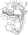
- FIG. 1 is shown in a perspective view of an optical measuring device 1 for a vehicle.
- the optical measuring device 1 comprises a housing 2.
- a transmission window 4 is formed on a front wall 3. Through the transmission window 4 pulsed laser light is emitted to the outside.
- the housing 2 comprises on the front wall 3 below the transmission window 4 a receiving window 5. This is formed in the embodiment larger than the transmitting window 4. About the receiving window 5 are received by detected in the vehicle environment objects back irradiated laser beams and from one in the housing. 2 arranged receiving unit processed.
- a transmission unit is also arranged in the housing 2.
- the transmitting unit comprises a transmitter board, not shown, on which, for example, an optical transmitter designed as a pulsed laser is arranged with transmitting optics.
- the receiver unit comprises a receiver board, not shown, on which, for example, an optical receiver designed as a detector is arranged, and moreover also has a receiving optical system, which may have a receiving lens and a deflection mirror as a receiving deflecting mirror.
- the optical receiver is preferably an APD diode.
- the transmitting unit can also have a deflecting mirror arrangement in the form of one or more transmitting deflecting mirrors, which are arranged radially spaced, for example, in a common horizontal plane on a carrier or holder.
- a coding disc can be arranged, which can be evaluated to determine the angle of rotation of this rotatable axis.
- sensors or sensors can be arranged for the evaluation of the coding disc.
- the optically stationary in the housing 2 stationary transmitter generates pulsed laser beams, which are deflected via said transmitting deflecting mirror and emitted by the transmitting window 4 in the monitored environment area.
- the receiving window 5 receives pulsed reflected laser beams which are reflected by objects or obstacles in response to the emitted pulsed laser beams.
- the received laser beams are conducted via the receiving unit to the fixed optical receiver.
- the output of the optical receiver is evaluated to determine the transit time of the laser beams to determine the distance to a known object in the surveillance area.
- a vehicle 6 which is a passenger car.
- the Fig. 2 shows a front-side view of the vehicle 6 wherein the optical measuring device 1 is arranged in the embodiment front side in the region of a grille 7 and objects in the surrounding area in front of the vehicle 6 are detectable.
- FIG. 3 an embodiment of subcomponents of the optical measuring device 1 is shown in a perspective view.
- This optical measuring device 1 comprises a carrier 8, which is thus formed in a region 9 for receiving the rotatably mounted components of a transmitting unit and also of the rotatably mounted components of a receiving unit. The rotation can take place about the axis A shown.
- the carrier 8 is designed to receive the fixed optical receiver 12, wherein it is arranged, for example, in a side wall 13 of the carrier 8.
- a slot-like depression 16 is formed in a first adjustment device 17.
- the first slot-like depression 16 extends in a straight line.
- the receiving lens 10 is formed quadrangular with respect to its peripheral contour. It is peripherally surrounded by a support frame 18 at least partially.
- the holding frame 18 has at a lower part to this part perpendicularly standing first engagement member 19.
- This first engagement element 19 is formed as a strip or plate-like planar element. It is as shown in Fig. 3 designed to engage in the first slot-like depression 16.
- the first engagement element 19 is shorter in terms of its extent in the x-direction than the first recess 16, so that this engagement element 19 in the straight direction in the first spatial direction according to the x-direction is linearly displaceable.
- a second engagement member 20 is disposed beyond. This is arranged on a lateral frame part standing outward. It instructs trapezoidal, horizontally projecting part 21, at the outer end of a vertically downwardly projecting part 22 is arranged.
- This second engagement element 20 engages in particular with the second part 22 in a formed on an upper side 23 of the side wall 13 further second slot-like recess 24 a.
- this slot-like depression 24 extends in the x-direction and is thus oriented parallel to the first slot-like depression 16.
- the extent of the second slot-like recess 24 in the x-direction is greater than the extension of the part 22 in this x-direction.
- This second engagement element 20 with the part 22 can thus also be linearly displaced back and forth in a defined and guided manner in the first spatial direction according to the x-direction.
- the receiving lens 10 which is fixedly connected to the holding frame 18, relative to the carrier 8 and thus also fixed to the carrier 8 optical receiver 12 are displaced position.
- the depressions 16 and 24 as well as the engagement elements 19 and 20 are designed such that not only a relative displacement of this first spatial direction in the x-direction can take place, but also a relative displacement in a perpendicular thereto second spatial direction, namely the y-direction. It can also be achieved that this receiving lens 10 is moved by means of this adjustment device 17 in the y-direction upwards or downwards relative to the carrier 8 and the engagement elements 16 and 20 still in engagement with the recesses 16 and 24.
- the deflection mirror 11 has an edge contour 26 which is trapezoidal.
- edge contour 26 which is trapezoidal.
- two opposite edge sides 27 and 28 are not formed to extend parallel.
- the deflecting mirror 11 has a trapezoidal shape in the embodiment and is also flat.
- a tapered end 29 of the deflecting mirror 11 is further spaced from this rear surface 25 as a wider end 30 of the deflecting mirror eleventh
- the deflecting mirror 11 is also positioned relative to the carrier 8 and thus also relative to the optical receiver 12 by a second adjustment device 31 at least in the second spatial direction according to the y-direction relative to the carrier.
- the second adjusting device 31 has a retaining clip 32 on which the upper edge side 27 of the deflection mirror 11 is fixedly connected.
- the headband is arranged in an engaging on an upper side 33 of a support web 34 which rests on the bottom 14, further slot-like recess 35 engaging.
- the second adjustment device 31 has a further retaining bracket 36 which is fixedly connected to a lower edge side 28 of the deflection mirror 11. This bracket 36 is in turn arranged to engage in a formed in the bottom 14 further slot-like recess 37 engaging.
- the deflecting mirror 11 can thus be moved precisely in the mentioned y-direction relative to the carrier 8 and / or the receiving lens 10 linearly.
- This relative position adjustment of said components namely the receiving lens 10, the deflecting mirror 11 and the carrier 8 (and thus of the fixed receiver 12) can take place before the positional fixing of these components to one another. If the correct adjustment achieved by this relative position adjustment option on the adjustment devices 17 and 31, this position can be fixed. This will be done in Fig. 3 not shown adhesive compounds formed. These adhesive compounds are formed in particular in the region between the engagement element 19 and the recess 16, the recess 24 and the engagement member 20, the headband 32 and the recess 35 and the headband 36 and the recess 37.
- Fig. 4 is in a further perspective view of the components according to Fig. 3 a state shown in which the deflecting mirror 11 with the brackets 32 and 36 taken from the recesses 35 and 37 is shown.
- FIG. 5 In contrast, a representation of the components according to Fig. 3 and Fig. 4 shown, in which the receiving lens 10 is shown with the holding frame 18 removed from the slots 16 and 24.
- Fig. 6 is in a further perspective view of the components according to the FIG. 3 to FIG. 5 shown the exploded view of the components.
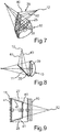
- Fig. 7 is a perspective view of shown below the receiving lens 10 and the deflection mirror 11, wherein also the beam path of a receiving beam 38 is shown beyond.
- the received over the receiving window 5 in the housing 2 and the receiving unit of the measuring device 1 receiving beam 38 strikes a front or front surface 39 of the receiving lens 10. Due to the curvature of the light in the receiving lens 39 is broken accordingly and occurs at the substantially flat rear surface 25 off. Due to the incidence of the receiving beam 38 and due to the refraction in the receiving lens 10, a receiving beam 38 is generated behind the receiving lens 10, which has the contour of the receiving beam 38 limiting edge steel 40, which form a corresponding trapezoidal shape.
- Fig. 8 is the top view of the illustration in Fig. 7 shown.
- FIG. 9 this trapezoidal contour 41 can be seen and shown accordingly.
- a view is shown on the front surface 39 and the mirror 11 disposed behind the receiving lens 10 is shown.
- the trapezoidal shape of the deflecting mirror 11 again shown, which essentially corresponds to the trapezoidal contour 41 of the marginal rays 40 of the receiving beam 38, as they impinge on the deflection mirror 11 corresponds.
- a conventional rectangular or square deflection mirror is shown by the dash-dotted outline representation. It can be clearly seen that a large area of the deflection mirror 11 for the deflection of the incident receiving beam 38 is not required by the conventional shape and therefore unnecessarily space is claimed in the known conventional embodiments. Due to the very individual shape-adapted design of the new deflecting mirror 11, this is prevented, but the entire receiving beam 38 is deflected and directed to the optical receiver 12.
Claims (13)
- Dispositif de mesure optique (1) pour un véhicule (6), comprenant au moins un émetteur optique, au moins un récepteur optique (12) et un arrangement de miroir de déviation ayant au moins un miroir de déviation (11) d'une unité de réception du dispositif de mesure (1), caractérisé en ce que le miroir de déviation (11) possède au moins deux côtés de bordure (27, 28) opposés qui ne s'étendent pas parallèlement l'un à l'autre, le miroir de déviation (11) présentant une forme trapézoïdale qui correspond sensiblement au contour trapézoïdal (41) des rayons marginaux (40) du faisceau de rayons de réception (38) tel qu'il est incident sur le miroir de déviation (11).
- Dispositif de mesure optique (1) selon la revendication 1, caractérisé en ce que le miroir de déviation (11) est plan.
- Dispositif de mesure optique (1) selon l'une des revendications précédentes, caractérisé en ce qu'une lentille de réception (10) est disposée avant le miroir de déviation (11) dans le trajet de rayon de réception, par laquelle est généré le contour (41) des rayons marginaux (40) formé après avoir traversé la lentille de réception (10).
- Dispositif de mesure optique (1) selon la revendication 3, caractérisé en ce que le miroir de déviation (11) est disposé en position inclinée par rapport à la lentille de réception (10) derrière celle-ci, notamment disposé avec son extrémité se rétrécissant (26) plus éloignée d'une surface arrière (25) de la lentille de réception (10) que son extrémité plus large (30) opposée.
- Dispositif de mesure optique (1) selon l'une des revendications précédentes, caractérisé en ce que le dispositif de mesure (1) possède un élément porteur (8) sur lequel est formé un premier dispositif d'ajustement (17) par le biais duquel la position d'une lentille de réception (10) du dispositif de mesure (1) qui est disposée dans le trajet de rayon de réception peut être réglée par rapport à l'élément porteur (8) et/ou est formé un deuxième dispositif d'ajustement (31) par le biais duquel la position du miroir de déviation (11) qui est disposé dans le trajet de rayon de réception peut être réglée par rapport à l'élément porteur (8).
- Dispositif de mesure optique (1) selon la revendication 5, caractérisé en ce que la lentille de réception (10) possède un cadre de maintien (18) sur lequel sont formés des éléments de prise (19, 20) destinés à venir en prise dans le premier dispositif d'ajustement (17), notamment le cadre de maintien (18) enserre au moins partiellement la lentille de réception (10) du côté du pourtour.
- Dispositif de mesure optique (1) selon la revendication 6, caractérisé en ce qu'un premier élément de prise (19) est disposé sur un bord inférieur du cadre de maintien (18) et est réalisé sous la forme d'une attache en forme de bande.
- Dispositif de mesure optique (1) selon la revendication 6 ou 7, caractérisé en ce qu'un premier évidement (16) de type fente du premier dispositif d'ajustement (17) est formé dans un fond (14) de l'élément porteur (8) et un premier élément de prise (19) est disposé dans le premier évidement (16) de manière à pouvoir coulisser de manière rectiligne dans une première direction spatiale et/ou dans une deuxième direction spatiale perpendiculaire à celle-ci avant le blocage de la position de la lentille de réception (10) par rapport à l'élément porteur (8).
- Dispositif de mesure optique (1) selon l'une des revendications précédentes 6 à 8, caractérisé en ce qu'un deuxième évidement (24) de type fente du premier dispositif d'ajustement (17) est formé dans une paroi latérale (13) de l'élément porteur (8) et un deuxième élément de prise (20) est disposé dans le deuxième évidement (24) de manière à pouvoir coulisser de manière rectiligne dans une première direction spatiale et/ou dans une deuxième direction spatiale perpendiculaire à celle-ci avant le blocage de la position de la lentille de réception (10) par rapport à l'élément porteur (8).
- Dispositif de mesure optique (1) selon l'une des revendications précédentes 5 à 9, caractérisé en ce que le deuxième dispositif d'ajustement (31) possède un premier évidement (35) de type fente dans une nervure d'élément porteur (34) de l'élément porteur (8), dans lequel peut être introduit un premier étrier de maintien (32) qui est relié à un côté de bordure supérieur (27) du miroir de déviation (11), le premier étrier de maintien (32) pouvant coulisser de manière rectiligne dans la deuxième direction spatiale par rapport à la nervure d'élément porteur (34) avant le blocage de la position du miroir de déviation (11) par rapport à l'élément porteur (8) et/ou le deuxième dispositif d'ajustement (31) possède un deuxième évidement (37) de type fente dans un fond (14) de l'élément porteur (8), dans lequel peut être introduit un deuxième étrier de maintien (36) qui est relié à un côté de bordure inférieur (28) du miroir de déviation (11), le deuxième étrier de maintien (36) pouvant coulisser de manière rectiligne dans la deuxième direction spatiale par rapport à l'élément porteur (8) avant le blocage de la position du miroir de déviation (11) par rapport à l'élément porteur (8).
- Dispositif de mesure optique (1) selon les revendications précédentes 5 à 10, caractérisé en ce que les positions relatives de la lentille de réception (10) par rapport à l'élément porteur (8) et du miroir de déviation (11) par rapport à l'élément porteur (8), réglées par le biais des dispositifs d'ajustement (17, 31), sont bloquées par des liaisons collées.
- Dispositif d'assistance au conducteur comprenant un dispositif de mesure optique (1) selon l'une des revendications précédentes.
- Véhicule (6) équipé d'un dispositif de mesure optique (1) selon l'une des revendications précédentes 1 à 11, le dispositif de mesure (1) étant configuré pour détecter des objets dans l'environnement du véhicule, le dispositif de mesure optique (1) étant notamment disposé sur le véhicule (1) au moins dans des composants partiels du côté avant, notamment dans la zone d'une calandre de radiateur (7).
Applications Claiming Priority (2)
| Application Number | Priority Date | Filing Date | Title |
|---|---|---|---|
| DE102011107585A DE102011107585A1 (de) | 2011-07-16 | 2011-07-16 | Optische Messvorrichtung für ein Fahrzeug, Fahrerassistenzeinrichtung mit einer derartigen Messvorrichtung sowie Fahrzeug mit einer entsprechenden Messvorrichtung |
| PCT/EP2012/063884 WO2013010978A2 (fr) | 2011-07-16 | 2012-07-16 | Dispositif de mesure optique pour un véhicule, dispositif d'aide à la conduite comprenant un dispositif de mesure de ce type et véhicule équipé d'un dispositif de mesure correspondant |
Publications (2)
| Publication Number | Publication Date |
|---|---|
| EP2732305A2 EP2732305A2 (fr) | 2014-05-21 |
| EP2732305B1 true EP2732305B1 (fr) | 2017-05-17 |
Family
ID=46583982
Family Applications (1)
| Application Number | Title | Priority Date | Filing Date |
|---|---|---|---|
| EP12740537.1A Active EP2732305B1 (fr) | 2011-07-16 | 2012-07-16 | Dispositif de mesure optique pour un véhicule, dispositif d'aide à la conduite comprenant un dispositif de mesure de ce type et véhicule équipé d'un dispositif de mesure correspondant |
Country Status (7)
| Country | Link |
|---|---|
| US (1) | US9575181B2 (fr) |
| EP (1) | EP2732305B1 (fr) |
| JP (1) | JP2014522983A (fr) |
| KR (1) | KR102068849B1 (fr) |
| CN (1) | CN103858020B (fr) |
| DE (1) | DE102011107585A1 (fr) |
| WO (1) | WO2013010978A2 (fr) |
Families Citing this family (5)
| Publication number | Priority date | Publication date | Assignee | Title |
|---|---|---|---|---|
| DE102011107594A1 (de) * | 2011-07-16 | 2013-01-17 | Valeo Schalter Und Sensoren Gmbh | Optische Messvorrichtung für ein Fahrzeug, Fahrerassistenzeinrichtung mit einer derartigen Messvorrichtung sowie Fahrzeug mit einer entsprechenden Messvorrichtung |
| DE102015108762A1 (de) * | 2015-06-03 | 2016-12-08 | Valeo Schalter Und Sensoren Gmbh | Haltevorrichtung zum Halten einer Antriebseinheit einer Umlenkspiegelanordnung, Detektionsvorrichtung mit einer Umlenkspiegelanordnung sowie Kraftfahrzeug |
| FR3056524B1 (fr) * | 2016-09-28 | 2018-10-12 | Valeo Systemes D'essuyage | Systeme de detection pour vehicule automobile |
| DE102018208897A1 (de) | 2018-06-06 | 2019-12-12 | Robert Bosch Gmbh | Empfangseinrichtung für ein Lidar-System |
| DE102019118029A1 (de) | 2019-07-04 | 2021-01-07 | Valeo Schalter Und Sensoren Gmbh | Optische Messvorrichtung zur Bestimmung von Objektinformationen von Objekten in wenigstens einem Überwachungsbereich |
Citations (1)
| Publication number | Priority date | Publication date | Assignee | Title |
|---|---|---|---|---|
| DE10244641A1 (de) * | 2002-09-25 | 2004-04-08 | Ibeo Automobile Sensor Gmbh | Optoelektronische Erfassungseinrichtung |
Family Cites Families (20)
| Publication number | Priority date | Publication date | Assignee | Title |
|---|---|---|---|---|
| JPS62153989A (ja) * | 1985-12-27 | 1987-07-08 | Fuji Photo Film Co Ltd | 電子写真フイルム用画像形成方法 |
| JP3489151B2 (ja) * | 1993-10-20 | 2004-01-19 | セイコーエプソン株式会社 | 光走査装置 |
| JP3336733B2 (ja) * | 1994-04-07 | 2002-10-21 | 株式会社村田製作所 | 移動手段用通信モジュール |
| JP3264109B2 (ja) * | 1994-10-21 | 2002-03-11 | 三菱電機株式会社 | 障害物検知装置 |
| JP3179322B2 (ja) * | 1995-12-06 | 2001-06-25 | 新日本製鐵株式会社 | 高出力レーザ伝送方法及び装置 |
| JP3271694B2 (ja) * | 1996-08-21 | 2002-04-02 | 三菱電機株式会社 | 光レーダ装置 |
| JP2000147124A (ja) * | 1998-11-12 | 2000-05-26 | Denso Corp | 車載レーダ装置 |
| JP4127579B2 (ja) * | 1998-12-22 | 2008-07-30 | 浜松ホトニクス株式会社 | 光波距離計 |
| WO2000048270A1 (fr) * | 1999-02-12 | 2000-08-17 | Tdk Corporation | Antenne a lentille et reseau d'antennes a lentille |
| JP2001108746A (ja) * | 1999-10-05 | 2001-04-20 | Mitsubishi Electric Corp | 光レーダ装置および光走査方法 |
| JP2003029184A (ja) * | 2001-07-11 | 2003-01-29 | Ricoh Co Ltd | 光走査装置及び画像形成装置 |
| DE10157378B4 (de) * | 2001-11-22 | 2012-10-25 | Robert Bosch Gmbh | Messgerät zur berührungslosen Abstandsmessung |
| FI113497B (fi) | 2002-02-28 | 2004-04-30 | Vaisala Oyj | Valotutka |
| JP4402400B2 (ja) * | 2003-08-28 | 2010-01-20 | オリンパス株式会社 | 物体認識装置 |
| US7302174B2 (en) * | 2003-12-31 | 2007-11-27 | Symbol Technologies, Inc. | Method and apparatus for capturing images using a color laser projection display |
| CN2840071Y (zh) * | 2005-08-30 | 2006-11-22 | 谢纯 | 汽车防撞驾驶装置 |
| DE102005055572B4 (de) | 2005-11-19 | 2007-08-02 | Ingenieurbüro Spies GbR (vertretungsberechtigte Gesellschafter: Hans Spies, Martin Spies, 86558 Hohenwart) | Abtastender optischer Abstandssensor |
| JP2008102401A (ja) * | 2006-10-20 | 2008-05-01 | Seiko Epson Corp | プロジェクタ及びテレビ |
| JP2008224620A (ja) * | 2007-03-15 | 2008-09-25 | Omron Corp | 測距装置 |
| US7710545B2 (en) | 2008-02-13 | 2010-05-04 | The Boeing Company | Scanned laser detection and ranging apparatus |
-
2011
- 2011-07-16 DE DE102011107585A patent/DE102011107585A1/de not_active Withdrawn
-
2012
- 2012-07-16 EP EP12740537.1A patent/EP2732305B1/fr active Active
- 2012-07-16 WO PCT/EP2012/063884 patent/WO2013010978A2/fr active Application Filing
- 2012-07-16 KR KR1020147001137A patent/KR102068849B1/ko active IP Right Grant
- 2012-07-16 CN CN201280035455.6A patent/CN103858020B/zh active Active
- 2012-07-16 US US14/131,501 patent/US9575181B2/en active Active
- 2012-07-16 JP JP2014520625A patent/JP2014522983A/ja active Pending
Patent Citations (1)
| Publication number | Priority date | Publication date | Assignee | Title |
|---|---|---|---|---|
| DE10244641A1 (de) * | 2002-09-25 | 2004-04-08 | Ibeo Automobile Sensor Gmbh | Optoelektronische Erfassungseinrichtung |
Also Published As
| Publication number | Publication date |
|---|---|
| WO2013010978A3 (fr) | 2013-04-04 |
| CN103858020B (zh) | 2016-08-24 |
| JP2014522983A (ja) | 2014-09-08 |
| WO2013010978A2 (fr) | 2013-01-24 |
| US20140326859A1 (en) | 2014-11-06 |
| KR102068849B1 (ko) | 2020-02-11 |
| US9575181B2 (en) | 2017-02-21 |
| EP2732305A2 (fr) | 2014-05-21 |
| KR20140039052A (ko) | 2014-03-31 |
| CN103858020A (zh) | 2014-06-11 |
| DE102011107585A1 (de) | 2013-01-17 |
Similar Documents
| Publication | Publication Date | Title |
|---|---|---|
| EP2732309B1 (fr) | Dispositif de mesure optique pour un véhicule, appareil d'assistance au conducteur comprenant un tel dispositif de mesure ainsi que véhicule équipé d'un dispositif de mesure correspondant | |
| EP3347732B1 (fr) | Dispositif de balayage laser pour véhicules automobiles | |
| EP2732305B1 (fr) | Dispositif de mesure optique pour un véhicule, dispositif d'aide à la conduite comprenant un dispositif de mesure de ce type et véhicule équipé d'un dispositif de mesure correspondant | |
| DE102007014034B3 (de) | Optischer Sensorchip und Einklemmschutzvorrichtung mit einem solchen | |
| DE102013012789A1 (de) | Abtastende optoelektronische Detektionseinrichtung und Kraftfahrzeug mit einer solchen Detektionseinrichtung | |
| EP2834661A1 (fr) | Dispositif de détection optoélectronique, en particulier scanneur à laser, comportant une unité de réception adaptée pour une réduction optimisée du niveau de réception | |
| EP1355128A1 (fr) | Alignement automatique d'un senseur | |
| EP3583444B1 (fr) | Capteur lidar servant à détecter un objet | |
| EP1515157A1 (fr) | Dispositif de détection optoélectronique | |
| EP3775978B1 (fr) | Dispositif lidar macroscopique | |
| WO2018149708A1 (fr) | Capteur lidar servant à détecter un objet | |
| DE102015112295A1 (de) | Sendeeinrichtung für eine optische Detektionsvorrichtung eines Kraftfahrzeugs, optische Detektionsvorrichtung, Kraftfahrzeug sowie Verfahren | |
| DE102015112296A1 (de) | Optische Sensorvorrichtung für ein Kraftfahrzeug, Kraftfahrzeug sowie Verfahren | |
| DE102017211817A1 (de) | LIDAR-Vorrichtung zum situationsabhängigen Abtasten von Raumwinkeln | |
| EP3289382A1 (fr) | Capteur laser destiné à un véhicule automobile et muni d'un miroir parabolique, système d'aide à la conduite, et véhicule automobile | |
| EP3516420B1 (fr) | Dispositif émetteur pour un dispositif de détection optique, dispositif de détection optique, véhicule automobile et procédé | |
| DE102016011328A1 (de) | LIDAR Scanner mit Pentaprisma | |
| EP3329300B1 (fr) | Dispositif capteur optique pour une véhicule pour balayage les environs de la véhicule en deux dimensions, véhicule et procédé | |
| DE102016118468A1 (de) | Erfassungsvorrichtung für ein Kraftfahrzeug, Fahrerassistenzsystem, Kraftfahrzeug sowie Verfahren | |
| EP3159712A1 (fr) | Procédé de liaison d'un groupe d'émission et d'un groupe de réception à une combinaison d'émission et de réception d'un dispositif de détection optoélectronique et dispositif de détection et véhicule en étant équipé | |
| WO2018054870A1 (fr) | Système d'émission pour un dispositif de détection optique, dispositif de détection optique, véhicule automobile ainsi que procédé | |
| DE102016011329A1 (de) | LiDAR Sensor mit in einem Rotorkörper angeordneter Optik | |
| DE102008025772A1 (de) | Vorrichtung zur Erfassung einer Umgebung eines Fahrzeugs umfassend mehrere oberflächenemittierende Laserdioden | |
| DE102021201006A1 (de) | LiDAR-System mit Ferndetektion | |
| WO2022223226A1 (fr) | Capteur lidar pour un véhicule, comportant un élément de réception pour focaliser dans une région de point focal, véhicule comprenant un capteur lidar et procédé de fonctionnement d'un capteur lidar |
Legal Events
| Date | Code | Title | Description |
|---|---|---|---|
| PUAI | Public reference made under article 153(3) epc to a published international application that has entered the european phase |
Free format text: ORIGINAL CODE: 0009012 |
|
| 17P | Request for examination filed |
Effective date: 20140113 |
|
| AK | Designated contracting states |
Kind code of ref document: A2 Designated state(s): AL AT BE BG CH CY CZ DE DK EE ES FI FR GB GR HR HU IE IS IT LI LT LU LV MC MK MT NL NO PL PT RO RS SE SI SK SM TR |
|
| DAX | Request for extension of the european patent (deleted) | ||
| 17Q | First examination report despatched |
Effective date: 20151202 |
|
| RIC1 | Information provided on ipc code assigned before grant |
Ipc: G01S 17/93 20060101ALI20161101BHEP Ipc: G01S 17/06 20060101ALI20161101BHEP Ipc: G01S 7/497 20060101ALI20161101BHEP Ipc: G01S 7/481 20060101AFI20161101BHEP |
|
| GRAP | Despatch of communication of intention to grant a patent |
Free format text: ORIGINAL CODE: EPIDOSNIGR1 |
|
| INTG | Intention to grant announced |
Effective date: 20161215 |
|
| GRAS | Grant fee paid |
Free format text: ORIGINAL CODE: EPIDOSNIGR3 |
|
| GRAA | (expected) grant |
Free format text: ORIGINAL CODE: 0009210 |
|
| AK | Designated contracting states |
Kind code of ref document: B1 Designated state(s): AL AT BE BG CH CY CZ DE DK EE ES FI FR GB GR HR HU IE IS IT LI LT LU LV MC MK MT NL NO PL PT RO RS SE SI SK SM TR |
|
| REG | Reference to a national code |
Ref country code: GB Ref legal event code: FG4D Free format text: NOT ENGLISH |
|
| REG | Reference to a national code |
Ref country code: CH Ref legal event code: EP |
|
| REG | Reference to a national code |
Ref country code: IE Ref legal event code: FG4D Free format text: LANGUAGE OF EP DOCUMENT: GERMAN |
|
| REG | Reference to a national code |
Ref country code: AT Ref legal event code: REF Ref document number: 894950 Country of ref document: AT Kind code of ref document: T Effective date: 20170615 |
|
| REG | Reference to a national code |
Ref country code: DE Ref legal event code: R096 Ref document number: 502012010374 Country of ref document: DE |
|
| REG | Reference to a national code |
Ref country code: FR Ref legal event code: PLFP Year of fee payment: 6 |
|
| REG | Reference to a national code |
Ref country code: SE Ref legal event code: TRGR |
|
| REG | Reference to a national code |
Ref country code: NL Ref legal event code: MP Effective date: 20170517 |
|
| REG | Reference to a national code |
Ref country code: LT Ref legal event code: MG4D |
|
| PG25 | Lapsed in a contracting state [announced via postgrant information from national office to epo] |
Ref country code: GR Free format text: LAPSE BECAUSE OF FAILURE TO SUBMIT A TRANSLATION OF THE DESCRIPTION OR TO PAY THE FEE WITHIN THE PRESCRIBED TIME-LIMIT Effective date: 20170818 Ref country code: NO Free format text: LAPSE BECAUSE OF FAILURE TO SUBMIT A TRANSLATION OF THE DESCRIPTION OR TO PAY THE FEE WITHIN THE PRESCRIBED TIME-LIMIT Effective date: 20170817 Ref country code: FI Free format text: LAPSE BECAUSE OF FAILURE TO SUBMIT A TRANSLATION OF THE DESCRIPTION OR TO PAY THE FEE WITHIN THE PRESCRIBED TIME-LIMIT Effective date: 20170517 Ref country code: LT Free format text: LAPSE BECAUSE OF FAILURE TO SUBMIT A TRANSLATION OF THE DESCRIPTION OR TO PAY THE FEE WITHIN THE PRESCRIBED TIME-LIMIT Effective date: 20170517 Ref country code: ES Free format text: LAPSE BECAUSE OF FAILURE TO SUBMIT A TRANSLATION OF THE DESCRIPTION OR TO PAY THE FEE WITHIN THE PRESCRIBED TIME-LIMIT Effective date: 20170517 Ref country code: HR Free format text: LAPSE BECAUSE OF FAILURE TO SUBMIT A TRANSLATION OF THE DESCRIPTION OR TO PAY THE FEE WITHIN THE PRESCRIBED TIME-LIMIT Effective date: 20170517 |
|
| PG25 | Lapsed in a contracting state [announced via postgrant information from national office to epo] |
Ref country code: BG Free format text: LAPSE BECAUSE OF FAILURE TO SUBMIT A TRANSLATION OF THE DESCRIPTION OR TO PAY THE FEE WITHIN THE PRESCRIBED TIME-LIMIT Effective date: 20170817 Ref country code: NL Free format text: LAPSE BECAUSE OF FAILURE TO SUBMIT A TRANSLATION OF THE DESCRIPTION OR TO PAY THE FEE WITHIN THE PRESCRIBED TIME-LIMIT Effective date: 20170517 Ref country code: IS Free format text: LAPSE BECAUSE OF FAILURE TO SUBMIT A TRANSLATION OF THE DESCRIPTION OR TO PAY THE FEE WITHIN THE PRESCRIBED TIME-LIMIT Effective date: 20170917 Ref country code: RS Free format text: LAPSE BECAUSE OF FAILURE TO SUBMIT A TRANSLATION OF THE DESCRIPTION OR TO PAY THE FEE WITHIN THE PRESCRIBED TIME-LIMIT Effective date: 20170517 Ref country code: PL Free format text: LAPSE BECAUSE OF FAILURE TO SUBMIT A TRANSLATION OF THE DESCRIPTION OR TO PAY THE FEE WITHIN THE PRESCRIBED TIME-LIMIT Effective date: 20170517 Ref country code: LV Free format text: LAPSE BECAUSE OF FAILURE TO SUBMIT A TRANSLATION OF THE DESCRIPTION OR TO PAY THE FEE WITHIN THE PRESCRIBED TIME-LIMIT Effective date: 20170517 |
|
| PG25 | Lapsed in a contracting state [announced via postgrant information from national office to epo] |
Ref country code: EE Free format text: LAPSE BECAUSE OF FAILURE TO SUBMIT A TRANSLATION OF THE DESCRIPTION OR TO PAY THE FEE WITHIN THE PRESCRIBED TIME-LIMIT Effective date: 20170517 Ref country code: SK Free format text: LAPSE BECAUSE OF FAILURE TO SUBMIT A TRANSLATION OF THE DESCRIPTION OR TO PAY THE FEE WITHIN THE PRESCRIBED TIME-LIMIT Effective date: 20170517 Ref country code: DK Free format text: LAPSE BECAUSE OF FAILURE TO SUBMIT A TRANSLATION OF THE DESCRIPTION OR TO PAY THE FEE WITHIN THE PRESCRIBED TIME-LIMIT Effective date: 20170517 Ref country code: CZ Free format text: LAPSE BECAUSE OF FAILURE TO SUBMIT A TRANSLATION OF THE DESCRIPTION OR TO PAY THE FEE WITHIN THE PRESCRIBED TIME-LIMIT Effective date: 20170517 Ref country code: RO Free format text: LAPSE BECAUSE OF FAILURE TO SUBMIT A TRANSLATION OF THE DESCRIPTION OR TO PAY THE FEE WITHIN THE PRESCRIBED TIME-LIMIT Effective date: 20170517 |
|
| REG | Reference to a national code |
Ref country code: DE Ref legal event code: R097 Ref document number: 502012010374 Country of ref document: DE |
|
| PG25 | Lapsed in a contracting state [announced via postgrant information from national office to epo] |
Ref country code: IT Free format text: LAPSE BECAUSE OF FAILURE TO SUBMIT A TRANSLATION OF THE DESCRIPTION OR TO PAY THE FEE WITHIN THE PRESCRIBED TIME-LIMIT Effective date: 20170517 Ref country code: SM Free format text: LAPSE BECAUSE OF FAILURE TO SUBMIT A TRANSLATION OF THE DESCRIPTION OR TO PAY THE FEE WITHIN THE PRESCRIBED TIME-LIMIT Effective date: 20170517 |
|
| REG | Reference to a national code |
Ref country code: CH Ref legal event code: PL |
|
| PLBE | No opposition filed within time limit |
Free format text: ORIGINAL CODE: 0009261 |
|
| STAA | Information on the status of an ep patent application or granted ep patent |
Free format text: STATUS: NO OPPOSITION FILED WITHIN TIME LIMIT |
|
| REG | Reference to a national code |
Ref country code: IE Ref legal event code: MM4A |
|
| 26N | No opposition filed |
Effective date: 20180220 |
|
| PG25 | Lapsed in a contracting state [announced via postgrant information from national office to epo] |
Ref country code: LI Free format text: LAPSE BECAUSE OF NON-PAYMENT OF DUE FEES Effective date: 20170731 Ref country code: IE Free format text: LAPSE BECAUSE OF NON-PAYMENT OF DUE FEES Effective date: 20170716 Ref country code: CH Free format text: LAPSE BECAUSE OF NON-PAYMENT OF DUE FEES Effective date: 20170731 |
|
| PG25 | Lapsed in a contracting state [announced via postgrant information from national office to epo] |
Ref country code: SI Free format text: LAPSE BECAUSE OF FAILURE TO SUBMIT A TRANSLATION OF THE DESCRIPTION OR TO PAY THE FEE WITHIN THE PRESCRIBED TIME-LIMIT Effective date: 20170517 |
|
| REG | Reference to a national code |
Ref country code: BE Ref legal event code: MM Effective date: 20170731 |
|
| PG25 | Lapsed in a contracting state [announced via postgrant information from national office to epo] |
Ref country code: LU Free format text: LAPSE BECAUSE OF NON-PAYMENT OF DUE FEES Effective date: 20170716 |
|
| REG | Reference to a national code |
Ref country code: FR Ref legal event code: PLFP Year of fee payment: 7 |
|
| PG25 | Lapsed in a contracting state [announced via postgrant information from national office to epo] |
Ref country code: BE Free format text: LAPSE BECAUSE OF NON-PAYMENT OF DUE FEES Effective date: 20170731 |
|
| REG | Reference to a national code |
Ref country code: AT Ref legal event code: MM01 Ref document number: 894950 Country of ref document: AT Kind code of ref document: T Effective date: 20170716 |
|
| PG25 | Lapsed in a contracting state [announced via postgrant information from national office to epo] |
Ref country code: MT Free format text: LAPSE BECAUSE OF FAILURE TO SUBMIT A TRANSLATION OF THE DESCRIPTION OR TO PAY THE FEE WITHIN THE PRESCRIBED TIME-LIMIT Effective date: 20170517 |
|
| PG25 | Lapsed in a contracting state [announced via postgrant information from national office to epo] |
Ref country code: AT Free format text: LAPSE BECAUSE OF NON-PAYMENT OF DUE FEES Effective date: 20170716 |
|
| PG25 | Lapsed in a contracting state [announced via postgrant information from national office to epo] |
Ref country code: HU Free format text: LAPSE BECAUSE OF FAILURE TO SUBMIT A TRANSLATION OF THE DESCRIPTION OR TO PAY THE FEE WITHIN THE PRESCRIBED TIME-LIMIT; INVALID AB INITIO Effective date: 20120716 Ref country code: MC Free format text: LAPSE BECAUSE OF FAILURE TO SUBMIT A TRANSLATION OF THE DESCRIPTION OR TO PAY THE FEE WITHIN THE PRESCRIBED TIME-LIMIT Effective date: 20170517 |
|
| PG25 | Lapsed in a contracting state [announced via postgrant information from national office to epo] |
Ref country code: CY Free format text: LAPSE BECAUSE OF NON-PAYMENT OF DUE FEES Effective date: 20170517 |
|
| PG25 | Lapsed in a contracting state [announced via postgrant information from national office to epo] |
Ref country code: MK Free format text: LAPSE BECAUSE OF FAILURE TO SUBMIT A TRANSLATION OF THE DESCRIPTION OR TO PAY THE FEE WITHIN THE PRESCRIBED TIME-LIMIT Effective date: 20170517 |
|
| PG25 | Lapsed in a contracting state [announced via postgrant information from national office to epo] |
Ref country code: TR Free format text: LAPSE BECAUSE OF FAILURE TO SUBMIT A TRANSLATION OF THE DESCRIPTION OR TO PAY THE FEE WITHIN THE PRESCRIBED TIME-LIMIT Effective date: 20170517 |
|
| PG25 | Lapsed in a contracting state [announced via postgrant information from national office to epo] |
Ref country code: PT Free format text: LAPSE BECAUSE OF FAILURE TO SUBMIT A TRANSLATION OF THE DESCRIPTION OR TO PAY THE FEE WITHIN THE PRESCRIBED TIME-LIMIT Effective date: 20170517 |
|
| PG25 | Lapsed in a contracting state [announced via postgrant information from national office to epo] |
Ref country code: AL Free format text: LAPSE BECAUSE OF FAILURE TO SUBMIT A TRANSLATION OF THE DESCRIPTION OR TO PAY THE FEE WITHIN THE PRESCRIBED TIME-LIMIT Effective date: 20170517 |
|
| P01 | Opt-out of the competence of the unified patent court (upc) registered |
Effective date: 20230528 |
|
| PGFP | Annual fee paid to national office [announced via postgrant information from national office to epo] |
Ref country code: GB Payment date: 20230725 Year of fee payment: 12 |
|
| PGFP | Annual fee paid to national office [announced via postgrant information from national office to epo] |
Ref country code: SE Payment date: 20230721 Year of fee payment: 12 Ref country code: FR Payment date: 20230727 Year of fee payment: 12 Ref country code: DE Payment date: 20230712 Year of fee payment: 12 |