EP2732305B1 - Optical measuring device of a vehicle, passenger assistance device comprising said type of measuring device and vehicle comprising a corresponding measuring device - Google Patents
Optical measuring device of a vehicle, passenger assistance device comprising said type of measuring device and vehicle comprising a corresponding measuring device Download PDFInfo
- Publication number
- EP2732305B1 EP2732305B1 EP12740537.1A EP12740537A EP2732305B1 EP 2732305 B1 EP2732305 B1 EP 2732305B1 EP 12740537 A EP12740537 A EP 12740537A EP 2732305 B1 EP2732305 B1 EP 2732305B1
- Authority
- EP
- European Patent Office
- Prior art keywords
- measuring apparatus
- support
- optical measuring
- deflection mirror
- depression
- Prior art date
- Legal status (The legal status is an assumption and is not a legal conclusion. Google has not performed a legal analysis and makes no representation as to the accuracy of the status listed.)
- Active
Links
- 230000003287 optical effect Effects 0.000 title claims description 63
- 239000000853 adhesive Substances 0.000 claims description 7
- 230000001070 adhesive effect Effects 0.000 claims description 7
- 238000011144 upstream manufacturing Methods 0.000 claims 1
- 238000006073 displacement reaction Methods 0.000 description 7
- 230000005540 biological transmission Effects 0.000 description 5
- 150000001875 compounds Chemical class 0.000 description 4
- 238000012544 monitoring process Methods 0.000 description 2
- 229910000831 Steel Inorganic materials 0.000 description 1
- 238000005352 clarification Methods 0.000 description 1
- 238000010276 construction Methods 0.000 description 1
- 230000007613 environmental effect Effects 0.000 description 1
- 238000011156 evaluation Methods 0.000 description 1
- 238000002955 isolation Methods 0.000 description 1
- 238000004519 manufacturing process Methods 0.000 description 1
- 238000000034 method Methods 0.000 description 1
- 230000035515 penetration Effects 0.000 description 1
- 230000002093 peripheral effect Effects 0.000 description 1
- 230000005855 radiation Effects 0.000 description 1
- 239000010959 steel Substances 0.000 description 1
Images


Classifications
-
- G—PHYSICS
- G01—MEASURING; TESTING
- G01S—RADIO DIRECTION-FINDING; RADIO NAVIGATION; DETERMINING DISTANCE OR VELOCITY BY USE OF RADIO WAVES; LOCATING OR PRESENCE-DETECTING BY USE OF THE REFLECTION OR RERADIATION OF RADIO WAVES; ANALOGOUS ARRANGEMENTS USING OTHER WAVES
- G01S17/00—Systems using the reflection or reradiation of electromagnetic waves other than radio waves, e.g. lidar systems
- G01S17/02—Systems using the reflection of electromagnetic waves other than radio waves
- G01S17/06—Systems determining position data of a target
-
- G—PHYSICS
- G01—MEASURING; TESTING
- G01S—RADIO DIRECTION-FINDING; RADIO NAVIGATION; DETERMINING DISTANCE OR VELOCITY BY USE OF RADIO WAVES; LOCATING OR PRESENCE-DETECTING BY USE OF THE REFLECTION OR RERADIATION OF RADIO WAVES; ANALOGOUS ARRANGEMENTS USING OTHER WAVES
- G01S17/00—Systems using the reflection or reradiation of electromagnetic waves other than radio waves, e.g. lidar systems
- G01S17/88—Lidar systems specially adapted for specific applications
- G01S17/93—Lidar systems specially adapted for specific applications for anti-collision purposes
- G01S17/931—Lidar systems specially adapted for specific applications for anti-collision purposes of land vehicles
-
- G—PHYSICS
- G01—MEASURING; TESTING
- G01S—RADIO DIRECTION-FINDING; RADIO NAVIGATION; DETERMINING DISTANCE OR VELOCITY BY USE OF RADIO WAVES; LOCATING OR PRESENCE-DETECTING BY USE OF THE REFLECTION OR RERADIATION OF RADIO WAVES; ANALOGOUS ARRANGEMENTS USING OTHER WAVES
- G01S7/00—Details of systems according to groups G01S13/00, G01S15/00, G01S17/00
- G01S7/48—Details of systems according to groups G01S13/00, G01S15/00, G01S17/00 of systems according to group G01S17/00
- G01S7/481—Constructional features, e.g. arrangements of optical elements
- G01S7/4817—Constructional features, e.g. arrangements of optical elements relating to scanning
-
- G—PHYSICS
- G01—MEASURING; TESTING
- G01S—RADIO DIRECTION-FINDING; RADIO NAVIGATION; DETERMINING DISTANCE OR VELOCITY BY USE OF RADIO WAVES; LOCATING OR PRESENCE-DETECTING BY USE OF THE REFLECTION OR RERADIATION OF RADIO WAVES; ANALOGOUS ARRANGEMENTS USING OTHER WAVES
- G01S7/00—Details of systems according to groups G01S13/00, G01S15/00, G01S17/00
- G01S7/48—Details of systems according to groups G01S13/00, G01S15/00, G01S17/00 of systems according to group G01S17/00
- G01S7/497—Means for monitoring or calibrating
- G01S7/4972—Alignment of sensor
Definitions
- the invention relates to an optical measuring device for a vehicle, comprising at least one optical transmitter, at least one optical receiver and a deflecting mirror arrangement with at least one deflecting mirror. Furthermore, the invention relates to a driver assistance device having such an optical measuring device as well as to a vehicle having such an optical measuring device.
- the prior art discloses scanning optical measuring devices, so-called laser scanners for vehicles for detecting objects or obstacles in a monitoring area in the vehicle environment, which determine the distance to objects or obstacles detected in the monitoring area according to the light pulse transit time method.
- a scanning optical distance sensor comprises at least one laser as an optical transmitter, at least one detector as an optical receiver and a deflection unit, which deflects a laser radiation onto the scene to be measured with a first mirror, and with a second mirror deflects the laser pulses scattered back from objects onto the at least one detector ,
- the first and second mirrors are arranged on a common rotatable axis on a respective holder and driven by a drive unit which is arranged between the two holders.
- a lidar with a transmitter, a receiver and an optical system for forming transmit beams and receive beams is known.
- the space requirement of the laser scanner must be minimized.
- the requirements of the structure of the receiving unit of the measuring device with the receiving lens, the deflection mirror and the sensor, which is usually an APD (Avalanche photodiode detector) sensor is very large.
- the adjustment of the sensor or the receiver within the receiving unit is very accurate, ie to perform on about 20 microns. It is an object of the present invention to provide an optical measuring device and a driver assistance device with such a measuring device as well as a vehicle with such a measuring device, which is constructed in a compact and space-minimized manner. This object is achieved by an optical measuring device, a
- An inventive optical measuring device for a vehicle comprises at least one optical transmitter, at least one optical receiver and a Umlenkspiegelanssen with at least one deflection mirror. It is provided that the deflection mirror of the receiving unit of the measuring device is adapted in its edge contour to the contour formed by marginal rays of a receiving beam. By such a configuration space is saved in a particular degree. In comparison to conventional embodiments of the deflecting mirror, which are usually designed rectangular or square, space is saved by this surface minimization of the deflecting mirror. This finding is based on the fact that when the beams arrive in the optical measuring device and in particular in the receiving unit they pass through a receiving lens and are refracted according to the shape of this receiving lens.
- the deflecting mirror After exiting the receiving lens, they therefore strike the deflecting mirror in a completely defined contour of the marginal rays which bound the receiving beam on the circumference. As this contour of the marginal rays is usually smaller than the area of the conventional deflecting mirrors in the receiving units, space is thereby given away.
- the functionality of the deflection mirror remains without restriction, but space can be saved the measuring device. In this space gained can now other components, such as an adjustment mechanism, fasteners and other components, such as the Justagevorraumen be arranged.
- the deflecting mirror is shaped in such a way that at least two opposite edge sides which do not run parallel to one another are formed.
- the deflecting mirror has a trapezoidal shape, or is trapezoidal. In a special minimization of the deflecting mirror, this takes into account the contour of the marginal rays after leaving the marginal rays characterizing a receiving beam.
- the deflecting mirror is also flat, so that in particular no parabolic mirror is used here.
- a possible disadvantage of parabolic mirrors which is that the focus is reduced to an existing receiver, thereby reducing the adjustable tolerance range, which leads to increased costs for the production, thus does not occur in these flat deflection mirrors.
- the receiving lens is arranged, through which the generated after the penetration of the receiving lens contour of the marginal rays of the receiving beam is generated.
- the deflecting mirror is arranged in particular inclined to the receiving lens behind this, in particular with its tapered end further spaced to the rear surface of the receiving lens arranged as having a wider end.
- the measuring device preferably has a carrier, on which at least some of the components transmitter, receiver and the deflecting mirror arrangement are arranged.
- a first adjustment device is formed on this support, by means of which a receiving lens arranged on the receiving beam path of the measuring devices is adjustable relative to the carrier in position and / or a second adjustment device is formed, through which a arranged in the receiving beam path deflection mirror is adjustable in position relative to the carrier ,
- the measuring device thus comprises in particular a receiving unit comprising the receiving lens and the deflection mirror, which can each be moved separately relative to the carrier and specifically positioned.
- the inventive optical measuring device it is therefore no longer necessary to actively move the receiver in a complicated and error-prone manner in its position relative to the carrier or have to position otherwise to create an adjusted overall unit can. Since, as already mentioned above, the Alignment must be made in the micrometer range, can already be fixed by the inventive optical measuring device of the receiver, in particular positioned on the carrier and must not be repositioned contrast. By contrast, the receiving lens and / or the deflecting mirror are made more individual and easier to change in their position by the adjustment devices that are created, and in particular can also be precisely repositioned in the sub-millimeter range mentioned.
- the receiver is thus mounted on a defined position on the carrier.
- the adjustment is carried out according to the invention, characterized in that arranged in the receiving unit deflecting mirror and / or arranged in the receiving unit receiving lens are moved separately and are then fixed in position after the correct positioning.
- the optical measuring device also comprises a transmitting unit, which has the optical transmitter, which can be, for example, a pulsed laser, and a transmitting optics.
- the transmitting optics can have one or more deflecting mirrors, which are referred to as a transmitting deflecting mirror.
- the at least one deflecting mirror assigned to the receiving unit can be referred to as the receiving deflecting mirror.
- the receiving lens has a holding frame, on which engaging elements are formed for engagement in the first adjusting device.
- the receiving lens is thus connected via the holding frame directly to the carrier, in this regard, the engagement takes place via the engagement elements in the integrated into the carrier first adjustment device.
- the holding frame surrounds the receiving lens circumferentially at least partially, for example, completely surrounds.
- a first engagement element is arranged on an underside of the holding frame and is designed as a strip-like tab.
- a particularly narrow and in view of a straight-line displacement of the receiving lens particularly suitable element can be provided. This also favors the space minimization significantly.
- a first slot-like depression of the first adjustment device is formed in a bottom of the carrier and a first engagement element of the holding frame in the first recess before fixing the position of the receiving lens to the carrier in a first spatial direction and / or in a second spatial direction perpendicular thereto rectilinear slidably arranged. It is thus created in a particularly noteworthy embodiment, an adjustment device, which makes it possible that the receiving lens in two mutually perpendicular spatial directions relative to the carrier and thus also to the optical receiver can be changed position.
- the slot-like depression is particularly advantageous in many respects.
- this groove or slot-like depression ensures, in particular precision of the movement guidance, the reception of the tab-like engagement element on the holding frame of the receiving lens. It can thus be ensured by the plate-like or strip-like configuration of the first engagement element, a linear displacement of the receiving lens in the direction of the slot-like depression.
- in vertical spatial direction to the engagement element is more or less sunk into this slot-like depression, so that in the second spatial direction quasi a height adjustment of the receiving lens relative to the carrier and thus also to the optical receiver is possible.
- a second slot-like depression of the first adjustment device is formed in a side wall of the carrier and a second engagement element in the second recess before the fixing of the position of the receiving lens to the carrier in a first spatial direction and / or in a second spatial direction perpendicular thereto arranged linearly displaceable is.
- the second adjustment device comprises a first slot-like recess accessible from above in a carrier piece of the carrier, in which a first retaining clip, which is connected to an upper edge of the deflecting mirror, is insertable, wherein the first retaining clip before fixing the position of the deflecting mirror to Carrier is relatively linearly displaceable relative to the carrier web in the second spatial direction.
- the second adjusting device has a second slot-like depression in a bottom of the carrier, in which a second retaining clip, which is connected to a lower edge of the deflecting mirror, can be inserted, wherein the second retaining clip before fixing the position of the deflecting mirror to the carrier relative to Carrier is linearly displaceable in the second spatial direction.
- the relative positions of the receiving lens, which are set via the adjusting device, to the carrier and the deflecting mirror to the carrier are fixed by adhesive compounds.
- the adhesive bonds are formed between the engaging elements of the holding frame and the slot-like recesses in the bottom and sidewalls of the carrier.
- the adhesive bonds are formed in particular between the brackets and the slot-like depressions.
- the invention relates to a driver assistance device having an optical measuring device according to the invention or an advantageous embodiment thereof.
- the invention also relates to a vehicle having an optical measuring device according to the invention or an advantageous embodiment thereof, wherein the measuring device is designed to detect objects in the vehicle environment.
- the optical measuring device is preferably arranged on the vehicle at least in partial components on the front side, in particular in the region of a radiator grille or radiator grille.
- FIG. 1 is shown in a perspective view of an optical measuring device 1 for a vehicle.
- the optical measuring device 1 comprises a housing 2.
- a transmission window 4 is formed on a front wall 3. Through the transmission window 4 pulsed laser light is emitted to the outside.
- the housing 2 comprises on the front wall 3 below the transmission window 4 a receiving window 5. This is formed in the embodiment larger than the transmitting window 4. About the receiving window 5 are received by detected in the vehicle environment objects back irradiated laser beams and from one in the housing. 2 arranged receiving unit processed.
- a transmission unit is also arranged in the housing 2.
- the transmitting unit comprises a transmitter board, not shown, on which, for example, an optical transmitter designed as a pulsed laser is arranged with transmitting optics.
- the receiver unit comprises a receiver board, not shown, on which, for example, an optical receiver designed as a detector is arranged, and moreover also has a receiving optical system, which may have a receiving lens and a deflection mirror as a receiving deflecting mirror.
- the optical receiver is preferably an APD diode.
- the transmitting unit can also have a deflecting mirror arrangement in the form of one or more transmitting deflecting mirrors, which are arranged radially spaced, for example, in a common horizontal plane on a carrier or holder.
- a coding disc can be arranged, which can be evaluated to determine the angle of rotation of this rotatable axis.
- sensors or sensors can be arranged for the evaluation of the coding disc.
- the optically stationary in the housing 2 stationary transmitter generates pulsed laser beams, which are deflected via said transmitting deflecting mirror and emitted by the transmitting window 4 in the monitored environment area.
- the receiving window 5 receives pulsed reflected laser beams which are reflected by objects or obstacles in response to the emitted pulsed laser beams.
- the received laser beams are conducted via the receiving unit to the fixed optical receiver.
- the output of the optical receiver is evaluated to determine the transit time of the laser beams to determine the distance to a known object in the surveillance area.
- a vehicle 6 which is a passenger car.
- the Fig. 2 shows a front-side view of the vehicle 6 wherein the optical measuring device 1 is arranged in the embodiment front side in the region of a grille 7 and objects in the surrounding area in front of the vehicle 6 are detectable.
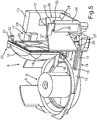
- FIG. 3 an embodiment of subcomponents of the optical measuring device 1 is shown in a perspective view.
- This optical measuring device 1 comprises a carrier 8, which is thus formed in a region 9 for receiving the rotatably mounted components of a transmitting unit and also of the rotatably mounted components of a receiving unit. The rotation can take place about the axis A shown.
- the carrier 8 is designed to receive the fixed optical receiver 12, wherein it is arranged, for example, in a side wall 13 of the carrier 8.
- a slot-like depression 16 is formed in a first adjustment device 17.
- the first slot-like depression 16 extends in a straight line.
- the receiving lens 10 is formed quadrangular with respect to its peripheral contour. It is peripherally surrounded by a support frame 18 at least partially.
- the holding frame 18 has at a lower part to this part perpendicularly standing first engagement member 19.
- This first engagement element 19 is formed as a strip or plate-like planar element. It is as shown in Fig. 3 designed to engage in the first slot-like depression 16.
- the first engagement element 19 is shorter in terms of its extent in the x-direction than the first recess 16, so that this engagement element 19 in the straight direction in the first spatial direction according to the x-direction is linearly displaceable.
- a second engagement member 20 is disposed beyond. This is arranged on a lateral frame part standing outward. It instructs trapezoidal, horizontally projecting part 21, at the outer end of a vertically downwardly projecting part 22 is arranged.
- This second engagement element 20 engages in particular with the second part 22 in a formed on an upper side 23 of the side wall 13 further second slot-like recess 24 a.
- this slot-like depression 24 extends in the x-direction and is thus oriented parallel to the first slot-like depression 16.
- the extent of the second slot-like recess 24 in the x-direction is greater than the extension of the part 22 in this x-direction.
- This second engagement element 20 with the part 22 can thus also be linearly displaced back and forth in a defined and guided manner in the first spatial direction according to the x-direction.
- the receiving lens 10 which is fixedly connected to the holding frame 18, relative to the carrier 8 and thus also fixed to the carrier 8 optical receiver 12 are displaced position.
- the depressions 16 and 24 as well as the engagement elements 19 and 20 are designed such that not only a relative displacement of this first spatial direction in the x-direction can take place, but also a relative displacement in a perpendicular thereto second spatial direction, namely the y-direction. It can also be achieved that this receiving lens 10 is moved by means of this adjustment device 17 in the y-direction upwards or downwards relative to the carrier 8 and the engagement elements 16 and 20 still in engagement with the recesses 16 and 24.
- the deflection mirror 11 has an edge contour 26 which is trapezoidal.
- edge contour 26 which is trapezoidal.
- two opposite edge sides 27 and 28 are not formed to extend parallel.
- the deflecting mirror 11 has a trapezoidal shape in the embodiment and is also flat.
- a tapered end 29 of the deflecting mirror 11 is further spaced from this rear surface 25 as a wider end 30 of the deflecting mirror eleventh
- the deflecting mirror 11 is also positioned relative to the carrier 8 and thus also relative to the optical receiver 12 by a second adjustment device 31 at least in the second spatial direction according to the y-direction relative to the carrier.
- the second adjusting device 31 has a retaining clip 32 on which the upper edge side 27 of the deflection mirror 11 is fixedly connected.
- the headband is arranged in an engaging on an upper side 33 of a support web 34 which rests on the bottom 14, further slot-like recess 35 engaging.
- the second adjustment device 31 has a further retaining bracket 36 which is fixedly connected to a lower edge side 28 of the deflection mirror 11. This bracket 36 is in turn arranged to engage in a formed in the bottom 14 further slot-like recess 37 engaging.
- the deflecting mirror 11 can thus be moved precisely in the mentioned y-direction relative to the carrier 8 and / or the receiving lens 10 linearly.
- This relative position adjustment of said components namely the receiving lens 10, the deflecting mirror 11 and the carrier 8 (and thus of the fixed receiver 12) can take place before the positional fixing of these components to one another. If the correct adjustment achieved by this relative position adjustment option on the adjustment devices 17 and 31, this position can be fixed. This will be done in Fig. 3 not shown adhesive compounds formed. These adhesive compounds are formed in particular in the region between the engagement element 19 and the recess 16, the recess 24 and the engagement member 20, the headband 32 and the recess 35 and the headband 36 and the recess 37.
- Fig. 4 is in a further perspective view of the components according to Fig. 3 a state shown in which the deflecting mirror 11 with the brackets 32 and 36 taken from the recesses 35 and 37 is shown.
- FIG. 5 In contrast, a representation of the components according to Fig. 3 and Fig. 4 shown, in which the receiving lens 10 is shown with the holding frame 18 removed from the slots 16 and 24.
- Fig. 6 is in a further perspective view of the components according to the FIG. 3 to FIG. 5 shown the exploded view of the components.
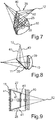
- Fig. 7 is a perspective view of shown below the receiving lens 10 and the deflection mirror 11, wherein also the beam path of a receiving beam 38 is shown beyond.
- the received over the receiving window 5 in the housing 2 and the receiving unit of the measuring device 1 receiving beam 38 strikes a front or front surface 39 of the receiving lens 10. Due to the curvature of the light in the receiving lens 39 is broken accordingly and occurs at the substantially flat rear surface 25 off. Due to the incidence of the receiving beam 38 and due to the refraction in the receiving lens 10, a receiving beam 38 is generated behind the receiving lens 10, which has the contour of the receiving beam 38 limiting edge steel 40, which form a corresponding trapezoidal shape.
- Fig. 8 is the top view of the illustration in Fig. 7 shown.
- FIG. 9 this trapezoidal contour 41 can be seen and shown accordingly.
- a view is shown on the front surface 39 and the mirror 11 disposed behind the receiving lens 10 is shown.
- the trapezoidal shape of the deflecting mirror 11 again shown, which essentially corresponds to the trapezoidal contour 41 of the marginal rays 40 of the receiving beam 38, as they impinge on the deflection mirror 11 corresponds.
- a conventional rectangular or square deflection mirror is shown by the dash-dotted outline representation. It can be clearly seen that a large area of the deflection mirror 11 for the deflection of the incident receiving beam 38 is not required by the conventional shape and therefore unnecessarily space is claimed in the known conventional embodiments. Due to the very individual shape-adapted design of the new deflecting mirror 11, this is prevented, but the entire receiving beam 38 is deflected and directed to the optical receiver 12.
Description
Die Erfindung betrifft eine optische Messvorrichtung für ein Fahrzeug, mit zumindest einem optischen Sender, zumindest einem optischen Empfänger und einer Umlenkspiegelanordnung mit zumindest einem Umlenkspiegel. Des Weiteren betrifft die Erfindung eine Fahrerassistenzeinrichtung mit einer derartigen optischen Messvorrichtung als auch ein Fahrzeug mit einer derartigen optischen Messvorrichtung.The invention relates to an optical measuring device for a vehicle, comprising at least one optical transmitter, at least one optical receiver and a deflecting mirror arrangement with at least one deflecting mirror. Furthermore, the invention relates to a driver assistance device having such an optical measuring device as well as to a vehicle having such an optical measuring device.
Aus dem Stand der Technik sind abtastende optische Messvorrichtungen, so genannte Laserscanner für Fahrzeuge zur Erkennung von Objekten bzw. Hindernissen in einem Überwachungsbereich in der Fahrzeugumgebung bekannt, welche die Entfernung zu im Überwachungsbereich erkannten Objekten bzw. Hindernissen nach dem Lichtimpulslaufzeitverfahren bestimmen.The prior art discloses scanning optical measuring devices, so-called laser scanners for vehicles for detecting objects or obstacles in a monitoring area in the vehicle environment, which determine the distance to objects or obstacles detected in the monitoring area according to the light pulse transit time method.
In der
Aus der
Aus der
Aufgrund der vorgesehenen Aufbaustelle des Laserscanners im Fahrzeug, d. h. beispielsweise am vorderen Teil vor dem Kühler, gegebenenfalls sogar direkt am Kühlergrill integriert, muss der Platzbedarf des Laserscanners minimiert werden. Die Anforderungen des Aufbaus der Empfangseinheit der Messvorrichtung mit der Empfangslinse, dem Umlenkspiegel und dem Sensor, welcher üblicherweise ein APD (Avalanche Photodiode Detector)-Sensor ist, sind sehr groß. Insbesondere ist die Justage des Sensors bzw. des Empfängers innerhalb der Empfangseinheit sehr genau, d. h. auf ca. 20 µm durchzuführen.
Es ist Aufgabe der vorliegenden Erfindung, eine optische Messvorrichtung sowie eine Fahrerassistenzeinrichtung mit einer derartigen Messvorrichtung als auch ein Fahrzeug mit einer derartigen Messvorrichtung zu schaffen, die kompakt und bauraumminimiert aufgebaut ist.
Diese Aufgabe wird durch eine optische Messvorrichtung, eineDue to the intended construction site of the laser scanner in the vehicle, ie, for example, at the front part in front of the radiator, possibly even integrated directly on the radiator grille, the space requirement of the laser scanner must be minimized. The requirements of the structure of the receiving unit of the measuring device with the receiving lens, the deflection mirror and the sensor, which is usually an APD (Avalanche photodiode detector) sensor is very large. In particular, the adjustment of the sensor or the receiver within the receiving unit is very accurate, ie to perform on about 20 microns.
It is an object of the present invention to provide an optical measuring device and a driver assistance device with such a measuring device as well as a vehicle with such a measuring device, which is constructed in a compact and space-minimized manner.
This object is achieved by an optical measuring device, a
Fahrerassistenzeinrichtung und ein Fahrzeug gemäß den unabhängigen Ansprüchen gelöst.
Eine erfindungsgemäße optische Messvorrichtung für ein Fahrzeug umfasst zumindest einen optischen Sender, zumindest einen optischen Empfänger und eine Umlenkspiegelanordnung mit zumindest einem Umlenkspiegel. Es ist vorgesehen, dass der Umlenkspiegel der Empfangseinheit der Messvorrichtung in seiner Randkontur an die durch Randstrahlen eines Empfangsstrahlenbündels gebildete Kontur angepasst ist. Durch eine derartige Ausgestaltung wird im besonderen Maße Bauraum eingespart. Im Vergleich zu herkömmlichen Ausgestaltungen des Umlenkspiegels, die üblicherweise rechteckig oder quadratisch gestaltet sind, wird durch diese Flächenminimierung des Umlenkspiegels Bauraum eingespart. Diese Erkenntnis beruht darauf, dass beim Eintreffen der Strahlen in die optische Messvorrichtung und insbesondere in die Empfangseinheit diese über eine Empfangslinse hindurchtreten und entsprechend der Form dieser Empfangslinse gebrochen werden. Nach dem Austritt aus der Empfangslinse treffen sie daher in ganz definierter Kontur der Randstrahlen, die das Empfangsstrahlenbündel umfangsseitig begrenzen auf den Umlenkspiegel auf. Da diese Kontur der Randstrahlen üblicherweise kleiner ist als die Fläche der herkömmlichen Umlenkspiegel in den Empfangseinheiten wird dadurch Bauraum verschenkt. Durch die erfindungsgemäße zusätzliche Ausgestaltung des Umlenkspiegels mit seiner ganz definierten und spezifischen Form wird daher diesem optischen Aspekt Rechnung getragen. Die Funktionalität des Umlenkspiegels bleibt ohne Einschränkung, dennoch kann Bauraum der Messvorrichtung eingespart werden. In diesem gewonnen Bauraum können nun andere Komponenten, wie beispielsweise eine Verstellmechanik, Befestigungselemente und andere Komponenten, beispielsweise der Justagevorrichtungen, angeordnet werden.Driver assistance device and a vehicle according to the independent claims solved.
An inventive optical measuring device for a vehicle comprises at least one optical transmitter, at least one optical receiver and a Umlenkspiegelanordnung with at least one deflection mirror. It is provided that the deflection mirror of the receiving unit of the measuring device is adapted in its edge contour to the contour formed by marginal rays of a receiving beam. By such a configuration space is saved in a particular degree. In comparison to conventional embodiments of the deflecting mirror, which are usually designed rectangular or square, space is saved by this surface minimization of the deflecting mirror. This finding is based on the fact that when the beams arrive in the optical measuring device and in particular in the receiving unit they pass through a receiving lens and are refracted according to the shape of this receiving lens. After exiting the receiving lens, they therefore strike the deflecting mirror in a completely defined contour of the marginal rays which bound the receiving beam on the circumference. As this contour of the marginal rays is usually smaller than the area of the conventional deflecting mirrors in the receiving units, space is thereby given away. The inventive additional embodiment of the deflection mirror with its completely defined and specific shape, therefore, this optical aspect is taken into account. The functionality of the deflection mirror remains without restriction, but space can be saved the measuring device. In this space gained can now other components, such as an adjustment mechanism, fasteners and other components, such as the Justagevorrichtungen be arranged.
Erfindungsgemäß ist der Umlenkspiegel so geformt, dass zumindest zwei nicht parallel zueinander verlaufende gegenüberliegende Randseiten ausgebildet werden.According to the invention, the deflecting mirror is shaped in such a way that at least two opposite edge sides which do not run parallel to one another are formed.
In der erfindungsgemäßen Ausführung ist vorgesehen, dass der Umlenkspiegel eine Trapezform aufweist, bzw. trapezförmig ausgebildet ist. Dies trägt in besonderer Minimierung des Umlenkspiegels der Kontur der Randstrahlen nach dem Verlassen der ein Empfangsstrahlenbündel charakterisierenden Randstrahlen Rechnung.In the embodiment according to the invention it is provided that the deflecting mirror has a trapezoidal shape, or is trapezoidal. In a special minimization of the deflecting mirror, this takes into account the contour of the marginal rays after leaving the marginal rays characterizing a receiving beam.
Der Umlenkspiegel ist darüber hinaus eben ausgebildet, sodass hier insbesondere kein Parabolspiegel eingesetzt ist. Ein möglicher Nachteil von Parabolspiegeln, der darin liegt, dass der Fokus zu einem vorhandenen Empfänger sich reduziert, wodurch sich der einstellbare Toleranzbereich reduziert, was für die Fertigung zu erhöhten Kosten führt, tritt somit bei diesen ebenen Umlenkspiegeln nicht auf.The deflecting mirror is also flat, so that in particular no parabolic mirror is used here. A possible disadvantage of parabolic mirrors, which is that the focus is reduced to an existing receiver, thereby reducing the adjustable tolerance range, which leads to increased costs for the production, thus does not occur in these flat deflection mirrors.
Vorzugsweise ist im Empfangsstrahlengang vor dem Umlenkspiegel die Empfangslinse angeordnet, durch welche die nach dem Durchdringen der Empfangslinse erzeugte Kontur der Randstrahlen des Empfangsstrahlenbündels erzeugt ist.Preferably, in the receiving beam path in front of the deflection mirror, the receiving lens is arranged, through which the generated after the penetration of the receiving lens contour of the marginal rays of the receiving beam is generated.
Der Umlenkspiegel ist insbesondere schräg gestellt zur Empfangslinse hinter dieser angeordnet, insbesondere mit seinem verjüngten Ende weiter beabstandet zur Hinterfläche der Empfangslinse angeordnet als mit einem breiteren Ende.The deflecting mirror is arranged in particular inclined to the receiving lens behind this, in particular with its tapered end further spaced to the rear surface of the receiving lens arranged as having a wider end.
Die Messvorrichtung weist vorzugsweise einen Träger auf, auf dem zumindest einige der Komponenten Sender, Empfänger und die Umlenkspiegelanordnung angeordnet sind. An diesen Träger ist eine erste Justagevorrichtung ausgebildet, durch welche eine am Empfangsstrahlengang angeordnete Empfangslinse der Messvorrichtungen in ihrer Position relativ zum Träger einstellbar ist und/oder eine zweite Justagevorrichtung ausgebildet ist, durch welche ein im Empfangsstrahlengang angeordneter Umlenkspiegel in seiner Position relativ zum Träger einstellbar ist. Die Messvorrichtung umfasst somit insbesondere eine Empfangseinheit umfassend die Empfangslinse und den Umlenkspiegel, die jeweils separat relativ zu dem Träger verschoben und spezifisch positioniert werden können.The measuring device preferably has a carrier, on which at least some of the components transmitter, receiver and the deflecting mirror arrangement are arranged. A first adjustment device is formed on this support, by means of which a receiving lens arranged on the receiving beam path of the measuring devices is adjustable relative to the carrier in position and / or a second adjustment device is formed, through which a arranged in the receiving beam path deflection mirror is adjustable in position relative to the carrier , The measuring device thus comprises in particular a receiving unit comprising the receiving lens and the deflection mirror, which can each be moved separately relative to the carrier and specifically positioned.
Durch die erfindungsgemäße optische Messvorrichtung ist es daher nicht mehr erforderlich, den Empfänger in aufwändiger und fehleranfälliger Weise in seiner Position relativ zum Träger aktiv verschieben bzw. anders positionieren zu müssen, um eine justierte Gesamteinheit schaffen zu können. Da, wie bereits oben angesprochen, die Justage in Mikrometerbereich zu erfolgen hat, kann durch die erfindungsgemäße optische Messvorrichtung der Empfänger bereits ortsfest insbesondere am Träger positioniert werden und muss demgegenüber nicht mehr umpositioniert werden. Die Empfangslinse und/oder der Umlenkspiegel sind demgegenüber durch die geschaffenen Justagevorrichtungen individueller und einfacher in ihrer Position zu verändern, insbesondere in dem genannten Submillimeterbereich auch präzise umzupositionieren.The inventive optical measuring device, it is therefore no longer necessary to actively move the receiver in a complicated and error-prone manner in its position relative to the carrier or have to position otherwise to create an adjusted overall unit can. Since, as already mentioned above, the Alignment must be made in the micrometer range, can already be fixed by the inventive optical measuring device of the receiver, in particular positioned on the carrier and must not be repositioned contrast. By contrast, the receiving lens and / or the deflecting mirror are made more individual and easier to change in their position by the adjustment devices that are created, and in particular can also be precisely repositioned in the sub-millimeter range mentioned.
Der Empfänger wird somit auf eine definierte Position auf den Träger montiert. Die Justage erfolgt gemäß der Erfindung dadurch, dass der in der Empfangseinheit angeordnete Umlenkspiegel und/oder die in der Empfangseinheit angeordnete Empfangslinse separat verschoben werden und dementsprechend dann nach der korrekten Positionierung positionsfixiert werden.The receiver is thus mounted on a defined position on the carrier. The adjustment is carried out according to the invention, characterized in that arranged in the receiving unit deflecting mirror and / or arranged in the receiving unit receiving lens are moved separately and are then fixed in position after the correct positioning.
Die optische Messvorrichtung umfasst darüber hinaus auch eine Sendeeinheit, welche den optischen Sender, der beispielsweise ein gepulst betreibbarer Laser sein kann, und eine Sendeoptik aufweist. Die Sendeoptik kann insbesondere einen oder mehrere Umlenkspiegel aufweisen, die als Sendeumlenkspiegel bezeichnet werden. Demgegenüber kann der zumindest eine, der Empfangseinheit zugeordnete Umlenkspiegel, als Empfangsumlenkspiegel bezeichnet werden.In addition, the optical measuring device also comprises a transmitting unit, which has the optical transmitter, which can be, for example, a pulsed laser, and a transmitting optics. In particular, the transmitting optics can have one or more deflecting mirrors, which are referred to as a transmitting deflecting mirror. In contrast, the at least one deflecting mirror assigned to the receiving unit can be referred to as the receiving deflecting mirror.
Vorzugsweise ist vorgesehen, dass die Empfangslinse einen Halterahmen aufweist, an dem Eingriffselemente zum Eingriff in die erste Justagevorrichtung ausgebildet sind. Die Empfangslinse ist somit über den Halterahmen direkt mit dem Träger verbunden, wobei diesbezüglich der Eingriff über die Eingriffselemente in die in den Träger integrierte erste Justagevorrichtung erfolgt.It is preferably provided that the receiving lens has a holding frame, on which engaging elements are formed for engagement in the first adjusting device. The receiving lens is thus connected via the holding frame directly to the carrier, in this regard, the engagement takes place via the engagement elements in the integrated into the carrier first adjustment device.
Vorzugsweise ist vorgesehen, dass der Halterahmen die Empfangslinse umfangsseitig zumindest teilweise umgreift, beispielsweise auch vollständig umgreift. Die mechanisch stabile Halterung und die genaue Justage im Hinblick auf die Einstellung der Relativposition der Empfangslinse zum Träger und somit auch zum daran ortsfest angeordneten Empfänger ist dadurch besonders präzise möglich.It is preferably provided that the holding frame surrounds the receiving lens circumferentially at least partially, for example, completely surrounds. The mechanically stable holder and the precise adjustment with regard to the adjustment of the relative position of the receiving lens to the carrier and thus also to the receiver arranged stationarily thereon is thus possible in a particularly precise manner.
Vorzugsweise ist vorgesehen, dass ein erstes Eingriffselement an einer Unterseite des Halterahmens angeordnet ist und als streifenartige Lasche ausgebildet ist. Dadurch kann ein besonders schmales und im Hinblick auf eine geradlinige Verschiebung der Empfangslinse besonders geeignetes Element bereitgestellt werden. Auch dies begünstigt die Bauraumminimierung wesentlich.It is preferably provided that a first engagement element is arranged on an underside of the holding frame and is designed as a strip-like tab. Thereby, a particularly narrow and in view of a straight-line displacement of the receiving lens particularly suitable element can be provided. This also favors the space minimization significantly.
Vorzugsweise ist vorgesehen, dass eine erste schlitzartige Vertiefung der ersten Justagevorrichtung in einem Boden des Trägers ausgebildet ist und ein erstes Eingriffselement des Halterahmens in der ersten Vertiefung vor der Positionsfixierung der Empfangslinse zum Träger in einer ersten Raumrichtung und/oder in einer dazu senkrechten zweiten Raumrichtung geradlinig verschiebbar angeordnet ist. Es wird also in einer besonders hervorzuhebenden Ausführung eine Justagevorrichtung geschaffen, die es ermöglicht, dass die Empfangslinse in zwei senkrecht zueinander stehenden Raumrichtungen relativ zum Träger und somit auch zum optischen Empfänger positionsverändert werden kann. Die schlitzartige Vertiefung ist in mehrerer Hinsicht dadurch besonders vorteilhaft. Indem sie in den Boden integriert und somit eingesenkt ist, kann sie im Hinblick auf die Bauhöhe des Bodens minimiert und insbesondere die Bauhöhe des Bodens nicht vergrößernd ausgebildet werden. Diese Nut bzw. schlitzartige Vertiefung gewährleistet darüber hinaus in besonderer Präzision der Bewegungsführung die Aufnahme des laschenartigen Eingriffselements am Halterahmen der Empfangslinse. Es kann somit durch die plattenartige bzw. streifenartige Ausgestaltung des ersten Eingriffselements eine Linearverschiebung der Empfangslinse in Richtung der schlitzartigen Vertiefung gewährleistet werden. Andererseits ist es jedoch auch möglich, dass in senkrechter Raumrichtung dazu das Eingriffselement mehr oder weniger in diese schlitzartige Vertiefung eingesenkt wird, sodass auch in der zweiten Raumrichtung quasi eine Höhenverstellung der Empfangslinse relativ zum Träger und somit auch zum optischen Empfänger möglich ist.It is preferably provided that a first slot-like depression of the first adjustment device is formed in a bottom of the carrier and a first engagement element of the holding frame in the first recess before fixing the position of the receiving lens to the carrier in a first spatial direction and / or in a second spatial direction perpendicular thereto rectilinear slidably arranged. It is thus created in a particularly noteworthy embodiment, an adjustment device, which makes it possible that the receiving lens in two mutually perpendicular spatial directions relative to the carrier and thus also to the optical receiver can be changed position. The slot-like depression is particularly advantageous in many respects. By being integrated into the ground and thus sunk into it, it can be minimized with regard to the overall height of the floor and, in particular, the building height of the floor can not be made larger. In addition, this groove or slot-like depression ensures, in particular precision of the movement guidance, the reception of the tab-like engagement element on the holding frame of the receiving lens. It can thus be ensured by the plate-like or strip-like configuration of the first engagement element, a linear displacement of the receiving lens in the direction of the slot-like depression. On the other hand, it is also possible that in vertical spatial direction to the engagement element is more or less sunk into this slot-like depression, so that in the second spatial direction quasi a height adjustment of the receiving lens relative to the carrier and thus also to the optical receiver is possible.
Vorzugsweise ist vorgesehen, dass eine zweite schlitzartige Vertiefung der ersten Justagevorrichtung in einer Seitenwand des Trägers ausgebildet ist und ein zweites Eingriffselement in der zweiten Vertiefung vor der Positionsfixierung der Empfangslinse zum Träger in einer ersten Raumrichtung und/oder in einer dazu senkrechten zweiten Raumrichtung gradlinig verschiebbar angeordnet ist. Die oben genannten Vorteile gelten hier analog.It is preferably provided that a second slot-like depression of the first adjustment device is formed in a side wall of the carrier and a second engagement element in the second recess before the fixing of the position of the receiving lens to the carrier in a first spatial direction and / or in a second spatial direction perpendicular thereto arranged linearly displaceable is. The above advantages apply analogously.
Darüber hinaus wird durch diese zweite schlitzartige Vertiefung eine zusätzliche mechanische Führung zur Justage geschaffen, sodass kein unerwünschtes Verkippen oder Verdrehen der Empfangslinse bei der geradlinigen Verschiebung in die erste Raumrichtung und/oder in die zweite Raumrichtung gegenüber dem Träger auftritt. Indem die beiden schlitzartigen Vertiefungen auch an unterschiedlichen Bauteilen des Trägers, nämlich einerseits dem Boden und andererseits einer Seitenwand ausgebildet sind, werden die oben genannten Vorteile bezüglich der stabilen Positionierung und möglichst geradlinigen Verschiebung nochmals bekräftigt.In addition, an additional mechanical guide for adjustment is created by this second slot-like depression, so that no unwanted tilting or twisting of the receiving lens in the rectilinear displacement in the first spatial direction and / or in the second spatial direction relative to the carrier occurs. By the two slot-like recesses are also formed on different components of the carrier, namely on the one hand the ground and on the other hand, a side wall, The above-mentioned advantages regarding the stable positioning and as straight-line displacement are reaffirmed.
Vorzugsweise ist vorgesehen, dass die zweite Justagevorrichtung eine von oben zugängliche erste schlitzartige Vertiefung in einem Trägerstück des Trägers aufweist, in welcher ein erster Haltebügel, der mit einer Oberkante des Umlenkspiegels verbunden ist, einführbar ist, wobei der erste Haltebügel vor der Positionsfixierung des Umlenkspiegels zum Träger relativ zum Trägersteg in der zweiten Raumrichtung geradlinig verschiebbar ist.Preferably, it is provided that the second adjustment device comprises a first slot-like recess accessible from above in a carrier piece of the carrier, in which a first retaining clip, which is connected to an upper edge of the deflecting mirror, is insertable, wherein the first retaining clip before fixing the position of the deflecting mirror to Carrier is relatively linearly displaceable relative to the carrier web in the second spatial direction.
Insbesondere ist vorgesehen, dass die zweite Justagevorrichtung eine zweite schlitzartige Vertiefung in einem Boden des Trägers aufweist, in welche ein zweiter Haltebügel, der mit einer Unterkante des Umlenkspiegels verbunden ist, einführbar ist, wobei der zweite Haltebügel vor der Positionsfixierung des Umlenkspiegels zum Träger relativ zum Träger in der zweiten Raumrichtung geradlinig verschiebbar ist.In particular, it is provided that the second adjusting device has a second slot-like depression in a bottom of the carrier, in which a second retaining clip, which is connected to a lower edge of the deflecting mirror, can be inserted, wherein the second retaining clip before fixing the position of the deflecting mirror to the carrier relative to Carrier is linearly displaceable in the second spatial direction.
Die für die Positionsverschiebung der Empfangslinse relativ zum Träger und somit auch zum optischen Empfänger dargelegten Vorteile gelten im gleichen Maße für die Positionsverschiebung des Umlenkspiegels relativ zum Träger und somit auch zum optischen Empfänger.The advantages set forth for the positional shift of the receiving lens relative to the carrier and thus also to the optical receiver apply equally to the positional shift of the deflecting mirror relative to the carrier and thus also to the optical receiver.
Vorzugsweise ist vorgesehen, dass die über die Justagevorrichtung eingestellten Relativpositionen der Empfangslinse zum Träger und des Umlenkspiegels zum Träger durch Klebstoffverbindungen fixiert sind.It is preferably provided that the relative positions of the receiving lens, which are set via the adjusting device, to the carrier and the deflecting mirror to the carrier are fixed by adhesive compounds.
Insbesondere ist somit vorgesehen, dass vor der Positionsfixierung der genannten Bauteile, nämlich des Trägers, der Empfangslinse und des Umlenkspiegels zueinander die Einstellung der Relativposition der drei Komponenten zueinander über die Positionsveränderung der Empfangslinse und/oder des Umlenkspiegels über die Justagevorrichtungen sehr präzise und definiert und auch gewollt erfolgt. Erst dann, wenn diese richtigen Relativpositionen zueinander gefunden sind, wird die Positionsfixierung der genannten Komponenten zueinander durchgeführt, indem die Klebstoffverbindungen ausgebildet werden. Die Klebstoffverbindungen werden insbesondere zwischen den Eingriffselementen des Halterahmens und den schlitzartigen Vertiefungen im Boden und den Seitenwänden des Trägers ausgebildet. Darüber hinaus werden auch die Klebeverbindungen insbesondere zwischen den Haltebügeln und den schlitzartigen Vertiefungen ausgebildet.In particular, it is thus provided that prior to fixing the position of said components, namely the carrier, the receiving lens and the deflecting mirror to each other, the adjustment of the relative position of the three components to each other via the change in position of the receiving lens and / or the deflecting mirror on the Justagevorrichtungen very precise and defined and also willfully takes place. Only then, when these correct relative positions are found to each other, the position fixing of said components to each other is performed by the adhesive compounds are formed. In particular, the adhesive bonds are formed between the engaging elements of the holding frame and the slot-like recesses in the bottom and sidewalls of the carrier. In addition, the adhesive bonds are formed in particular between the brackets and the slot-like depressions.
Des Weiteren betrifft die Erfindung eine Fahrerassistenzeinrichtung mit einer erfindungsgemäßen optischen Messvorrichtung oder einer vorteilhaften Ausgestaltung davon.Furthermore, the invention relates to a driver assistance device having an optical measuring device according to the invention or an advantageous embodiment thereof.
Die Erfindung betrifft darüber hinaus auch ein Fahrzeug mit einer erfindungsgemäßen optischen Messvorrichtung oder einer vorteilhaften Ausgestaltung davon, wobei die Messvorrichtung zur Erfassung von Objekten in der Fahrzeugumgebung ausgebildet ist. Vorzugsweise ist die optische Messvorrichtung zumindest in Teilkomponenten frontseitig, insbesondere im Bereich eines Kühlergrills bzw. Kühlergitters, am Fahrzeug angeordnet.The invention also relates to a vehicle having an optical measuring device according to the invention or an advantageous embodiment thereof, wherein the measuring device is designed to detect objects in the vehicle environment. The optical measuring device is preferably arranged on the vehicle at least in partial components on the front side, in particular in the region of a radiator grille or radiator grille.
Weitere Merkmale der Erfindung ergeben sich aus den Ansprüchen, den Figuren und der Figurenbeschreibung. Die vorstehend in der Beschreibung genannten Merkmale und Merkmalskombinationen sowie die nachfolgend in der Figurenbeschreibung genannten und/oder in den Figuren alleine gezeigten Merkmale und Merkmalskombinationen sind nicht nur in der jeweils angegebenen Kombination, sondern auch in anderen Kombinationen oder in Alleinstellung verwendbar, ohne den Rahmen der Erfindung zu verlassen.Further features of the invention will become apparent from the claims, the figures and the description of the figures. The features and feature combinations mentioned above in the description as well as the features and feature combinations mentioned below in the description of the figures and / or in the figures alone can be used not only in the respectively specified combination but also in other combinations or in isolation, without the scope of To leave invention.
Ausführungsbeispiele der Erfindung werden nachfolgend anhand schematischer Zeichnungen näher erläutert. Es zeigen:
- Fig. 1
- eine perspektivische Darstellung eines Ausführungsbeispiels einer erfindungsgemäßen optischen Messvorrichtung;
- Fig. 2
- eine schematische Darstellung eines Ausführungsbeispiels eines erfindungsgemäßen Fahrzeugs mit einer derartigen optischen Messvorrichtung;
- Fig. 3
- eine perspektivische Darstellung von Teilkomponenten eines Ausführungsbeispiels einer erfindungsgemäßen optischen Messvorrichtung in einer ersten Positionierung des Trägers, der Empfangslinse und eines Umlenkspiegels der Empfangseinheit;
- Fig. 4
- eine perspektivische Darstellung der Teilkomponenten gemäß
Fig. 3 in einer zweiten Position der Komponenten zueinander; - Fig. 5
- eine perspektivische Darstellung der Komponenten gemäß
Fig. 3 undFig. 4 in weiterer unterschiedlicher Position der Komponenten zueinander; - Fig. 6
- eine weitere perspektivische Darstellung der Komponenten gemäß
Fig. 3 bis Fig. 5 in einer weiteren Explosionsdarstellung der Komponenten; - Fig. 7
- eine perspektivische Darstellung der Empfangslinse und eines Umlenkspiegels einer Empfangseinheit mit einem gezeigten Strahlenverlauf eines Empfangsstrahlenbündels;
- Fig. 8
- eine Draufsicht auf die Darstellung gemäß
Fig. 7 ; und - Fig. 9
- eine weitere perspektivische Darstellung der Empfangslinse und verschiedenen Formen eines Umlenkspiegels mit der beispielhaften trapezförmigen Kontur der Randstrahlen des Empfangsstrahlenbündels.
- Fig. 1
- a perspective view of an embodiment of an optical measuring device according to the invention;
- Fig. 2
- a schematic representation of an embodiment of a vehicle according to the invention with such an optical measuring device;
- Fig. 3
- a perspective view of subcomponents of an embodiment of an optical measuring device according to the invention in a first positioning of the carrier, the receiving lens and a deflection mirror of the receiving unit;
- Fig. 4
- a perspective view of the sub-components according to
Fig. 3 in a second position of the components to each other; - Fig. 5
- a perspective view of the components according to
Fig. 3 andFig. 4 in a further different position of the components to each other; - Fig. 6
- a further perspective view of the components according to
FIG. 3 to FIG. 5 in a further exploded view of the components; - Fig. 7
- a perspective view of the receiving lens and a deflection mirror of a receiving unit with a shown beam path of a receive beam;
- Fig. 8
- a plan view of the illustration according to
Fig. 7 ; and - Fig. 9
- a further perspective view of the receiving lens and various shapes of a deflecting mirror with the exemplary trapezoidal contour of the marginal rays of the receiving beam.
In den Figuren werden gleiche oder funktionsgleiche Elemente mit den gleichen Bezugszeichen versehen.In the figures, identical or functionally identical elements are provided with the same reference numerals.
In
Darüber hinaus umfasst das Gehäuse 2 an der Frontwand 3 unterhalb des Sendefensters 4 ein Empfangsfenster 5. Dieses ist im Ausführungsbeispiel größer ausgebildet als das Sendefenster 4. Über das Empfangsfenster 5 werden von in der Fahrzeugumgebung detektierten Objekten zurückgestrahlte Laserstrahlen empfangen und von einer in dem Gehäuse 2 angeordneten Empfangseinheit verarbeitet.In addition, the
Neben der Empfangseinheit ist in dem Gehäuse 2 auch eine Sendeeinheit angeordnet. Die Sendeeinheit umfasst eine nicht gezeigte Senderplatine, auf welcher beispielsweise ein als gepulster Laser ausgeführter optischer Sender mit einer Sendeoptik angeordnet ist.In addition to the receiving unit, a transmission unit is also arranged in the
Die Empfängereinheit umfasst eine nicht dargestellte Empfängerplatine, auf welcher beispielsweise ein als Detektor ausgeführter optischer Empfänger angeordnet ist, und darüber hinaus auch eine Empfangsoptik aufweist, welche eine Empfangslinse und einen Umlenkspiegel als Empfangsumlenkspiegel aufweisen kann.The receiver unit comprises a receiver board, not shown, on which, for example, an optical receiver designed as a detector is arranged, and moreover also has a receiving optical system, which may have a receiving lens and a deflection mirror as a receiving deflecting mirror.
Der optische Empfänger ist vorzugsweise eine APD-Diode.The optical receiver is preferably an APD diode.
Die Sendeeinheit kann darüber hinaus auch noch eine Umlenkspiegelanordnung in Form von einem oder mehreren Sendeumlenkspiegeln aufweisen, welche beispielsweise in einer gemeinsamen horizontalen Ebene radial beabstandet auf einem Träger bzw. Halter angeordnet sind.In addition, the transmitting unit can also have a deflecting mirror arrangement in the form of one or more transmitting deflecting mirrors, which are arranged radially spaced, for example, in a common horizontal plane on a carrier or holder.
Es kann darüber hinaus auch noch eine andere Betriebseinheit vorgesehen sein, welche die drehbare Achse, um die die Sendeumlenkspiegel gemeinsam drehbar sind, antreibt.In addition, it is also possible to provide another operating unit which drives the rotatable axle about which the transmission deflecting mirrors are rotatable together.
Zwischen den Sendeumlenkspiegeln und der Empfangseinheit, insbesondere der Empfangslinse und dem Empfangsumlenkspiegel kann eine Kodierscheibe angeordnet sein, welche zur Bestimmung des Drehwinkels dieser drehbaren Achse auswertbar ist. Zur Auswertung der Kodierscheibe können entsprechende Aufnehmer bzw. Sensoren angeordnet sein.Between the Sendeumlenkspiegeln and the receiving unit, in particular the receiving lens and the Empfangsumlenkspiegel a coding disc can be arranged, which can be evaluated to determine the angle of rotation of this rotatable axis. For the evaluation of the coding disc corresponding sensors or sensors can be arranged.
Der optische örtlich im Gehäuse 2 feststehende Sender erzeugt gepulste Laserstrahlen, welche über die genannten Sendeumlenkspiegel umgelenkt und durch das Sendefenster 4 in den zu überwachenden Umgebungsbereich abgestrahlt werden. Über das Empfangsfenster 5 werden gepulste reflektierte Laserstrahlen empfangen, die in Reaktion auf die ausgesendeten gepulsten Laserstrahlen von Objekten bzw. Hindernissen reflektiert werden. Die empfangenen Laserstrahlen werden über die Empfangseinheit zum feststehenden optischen Empfänger geleitet. Das Ausgangssignal des optischen Empfängers wird zur Ermittlung der Laufzeit der Laserstrahlen ausgewertet, um die Entfernung zu einem bekannten Objekt in dem Überwachungsbereich zu ermitteln.The optically stationary in the
In
In
Der Übersichtlichkeit dienend sind diese genannten Komponenten hier nicht gezeigt. Ein wesentlicher Punkt der vorliegenden Erfindung ist auch anhand der in
Der Träger 8, der im inneren des Gehäuses 2 angeordnet ist, ist zur Aufnahme der angesprochenen Empfangslinse 10 sowie eines der Empfangseinheit zugeordneten Umlenkspiegels 11 ausgebildet. Darüber hinaus ist der Träger 8 zur Aufnahme des feststehenden optischen Empfängers 12 ausgebildet, wobei dieser beispielsweise in einer Seitenwand 13 des Trägers 8 angeordnet ist. Der einstückig ausgebildete Träger 8, der insbesondere aus Kunststoff ist, weist darüber hinaus auch einen Boden 14 auf, an dem die vertikal stehende Seitenwand 13 angeformt ist.The
An einer Oberseite 15 des Bodens 14 ist eine schlitzartige Vertiefung 16 in einer ersten Justagevorrichtung 17 ausgebildet. Die erste schlitzartige Vertiefung 16 erstreckt sich geradlinig.On a top 15 of the bottom 14, a slot-
Sie erstreckt sich in eine erste Raumrichtung, nämlich der x-Richtung.It extends in a first spatial direction, namely the x-direction.
Die Empfangslinse 10 ist im Hinblick auf ihre Umfangskontur viereckig ausgebildet. Sie ist umfangsseitig durch einen Halterahmen 18 zumindest teilweise umgeben. Der Halterahmen 18 weist an einem unteren Teil ein zu diesem Teil senkrecht stehendes erstes Eingriffselement 19 auf. Dieses erste Eingriffselement 19 ist als Streifen bzw. plattenartiges ebenes Element ausgebildet. Es ist gemäß der Darstellung in
An dem Halterahmen 18 ist darüber hinaus ein zweites Eingriffselement 20 angeordnet. Dieses ist an einem seitlichen Rahmenteil nach außen stehend angeordnet. Es weist ein trapezförmiges, horizontal abstehendes Teil 21 auf, an dessen äußeren Ende ein vertikal nach unten stehendes Teil 22 angeordnet ist.On the holding
Dieses zweite Eingriffselement 20 greift insbesondere mit dem zweiten Teil 22 in eine an einer Oberseite 23 der Seitenwand 13 ausgebildete weitere zweite schlitzartige Vertiefung 24 ein. Auch hier ist vorgesehen, dass sich diese schlitzartige Vertiefung 24 in x-Richtung erstreckt und somit parallel zur ersten schlitzartigen Vertiefung 16 orientiert ist. Auch hier ist die Erstreckung der zweiten schlitzartigen Vertiefung 24 in x-Richtung größer als die Ausdehnung des Teils 22 in diese x-Richtung. Auch dieses zweite Eingriffselement 20 mit dem Teil 22 kann somit in der ersten Raumrichtung gemäß der x-Richtung in definierter und geführter Weise linear hin und her verschoben werden.This
Durch diese Verschiebemöglichkeit kann die Empfangslinse 10, die fest mit dem Halterahmen 18 verbunden ist, relativ zum Träger 8 und somit auch zum am Träger 8 feststehenden optischen Empfänger 12 positionsverschoben werden.By this displacement possibility, the receiving
Darüber hinaus ist vorgesehen, dass die Vertiefungen 16 und 24 sowie auch die Eingriffselemente 19 und 20 derart gestaltet sind, dass nicht nur eine Relativverschiebung dieser ersten Raumrichtung in x-Richtung erfolgen kann, sondern auch eine Relativverschiebung in einer dazu senkrechten zweiten Raumrichtung, nämlich der y-Richtung. Es kann nämlich auch erreicht werden, dass diese Empfangslinse 10 mittels dieser Justagevorrichtung 17 in y-Richtung nach oben oder nach unten gegenüber dem Träger 8 verschoben wird und die Eingriffselemente 16 und 20 dennoch weiterhin im Eingriff mit den Vertiefungen 16 und 24 sind.In addition, it is provided that the
Darüber hinaus ist es auch gewährleistet, dass der gegenüber einer sich insbesondere in der y-z-Ebene erstreckenden Hinterfläche 25 der Empfangslinse 10 dahinter angeordnete Umlenkspiegel 11 schräg geneigt dazu orientiert, wie dies in
Wie aus der Darstellung in
Der Umlenkspiegel 11 weist im Ausführungsbeispiel eine Trapezform auf und ist darüber hinaus eben ausgebildet.The deflecting
Wie aus der Darstellung in
Der Umlenkspiegel 11 ist darüber hinaus durch eine zweite Justagevorrichtung 31 zumindest in der zweiten Raumrichtung gemäß der y-Richtung relativ verschiebbar gegenüber dem Träger 8 und somit auch gegenüber dem optischen Empfänger 12 positionierbar.The deflecting
Die zweite Justagevorrichtung 31 weist einen Haltebügel 32 auf der mit der oberen Randseite 27 des Umlenkspiegels 11 fest verbunden ist. Darüber hinaus ist der Haltebügel in eine an einer Oberseite 33 eines Trägerstegs 34, der auf dem Boden 14 aufsitzt, ausgebildete weitere schlitzartige Vertiefung 35 eingreifend angeordnet.The
Darüber hinaus ist vorgesehen, dass die zweite Justagevorrichtung 31 einen weiteren Haltebügel 36 aufweist, der mit einer unteren Randseite 28 des Umlenkspiegels 11 fest verbunden ist. Dieser Haltebügel 36 ist wiederum zum Eingriff in eine in dem Boden 14 ausgebildete weitere schlitzartige Vertiefung 37 eingreifend angeordnet.In addition, it is provided that the
Der Umlenkspiegel 11 kann somit präzise geführt in der genannten y-Richtung relativ gegenüber dem Träger 8 und/oder der Empfangslinse 10 linear verschoben werden.The deflecting
Diese relative Positionseinstellung der genannten Komponenten, nämlich der Empfangslinse 10, des Umlenkspiegels 11 und des Trägers 8 (und damit des feststehenden Empfängers 12) kann vor der Positionsfixierung dieser genannten Komponenten zueinander erfolgen. Ist die richtige Justage durch diese relative Positionseinstellungsmöglichkeit über die Justagevorrichtungen 17 und 31 erreicht, so kann diese Position fixiert werden. Dazu werden in
In
In
In
In
In
Claims (13)
- Optical measuring apparatus (1) for a vehicle (6), having at least one optical transmitter, at least one optical receiver (12) and a deflection mirror arrangement having at least one deflection mirror (11) of a reception unit of the measuring apparatus (1), characterized in that the deflection mirror (11) has at least two opposite edge sides (27, 28) that do not run parallel to one another, wherein the deflection mirror (11) has a trapezoidal shape which essentially corresponds to the trapezoidal contour (41) of the marginal rays (40) of the received beam (38), as they impinge on the deflection mirror (11).
- Optical measuring apparatus (1) according to Claim 1,
characterized in that
the deflection mirror (11) is planar. - Optical measuring apparatus (1) according to either of the preceding claims,
characterized in that
the received ray path upstream of the deflection mirror (11) contains a reception lens (10) that has produced the contour (41) of the marginal rays (40) that is formed after the reception lens (10) is penetrated. - Optical measuring apparatus (1) according to Claim 3,
characterized in that
the deflection mirror (11) is arranged obliquely with respect to the reception lens (10) behind the latter, in particular is arranged with its tapered end (26) further apart from a rear face (25) of the reception lens (10) than its opposite wider end (30). - Optical measuring apparatus (1) according to one of the preceding claims,
characterized in that
the measuring apparatus (1) has a support (8) on which a first alignment apparatus (17) is formed that can set the position of a reception lens (10) of the measuring apparatus (1), which reception lens is arranged in the received ray path, relative to the support (8) and/or a second alignment apparatus (31) is formed that can set the position of the deflection mirror (11), which is arranged in the received ray path, relative to the support (8). - Optical measuring apparatus (1) according to Claim 5,
characterized in that
the reception lens (10) has a retaining frame (18) on which engagement elements (19, 20) for engaging in the first alignment apparatus (17) are formed, in particular the retaining frame (18) at least partially encompasses the perimeter of the reception lens (10). - Optical measuring apparatus (1) according to Claim 6,
characterized in that
a first engagement element (19) is arranged on a lower edge of the retaining frame (18) and is in the form of a strip-like bracket. - Optical measuring apparatus (1) according to Claim 6 or 7,
characterized in that
a first slot-like depression (16) in the first alignment apparatus (17) is formed in a base (14) of the support (8) and a first engagement element (19) is arranged in the first depression (16) so as to be rectilinearly displaceable in a first spatial direction and/or in a second spatial direction, which is perpendicular thereto, prior to the fixing of the position of the reception lens (10) in relation to the support (8). - Optical measuring apparatus (1) according to one of the preceding Claims 6 to 8,
characterized in that
a second slot-like depression (24) in the first alignment apparatus (17) is formed in a lateral wall (13) of the support (8) and a second engagement element (20) is arranged in the second depression (54) so as to be rectilinearly displaceable in a first spatial direction and/or in a second spatial direction, which is perpendicular thereto, prior to the fixing of the position of the reception lens (10) in relation to the support (8). - Optical measuring apparatus (1) according to one of the preceding Claims 5 to 9,
characterized in that
the second alignment apparatus (31) has a first slot-like depression (35), which is accessible from above, in a support web (34) of the support (8), into which depression a first retaining leg (32), which is connected to an upper edge side (27) of the deflection mirror (11), can be introduced, wherein the first retaining leg (32) is rectilinearly displaceable relative to the support web (34) in the second spatial direction prior to the fixing of the position of the deflection mirror (11) in relation to the support (8), and/or the second alignment apparatus (31) has a second slot-like depression (37) in a base (14) of the support (8), into which depression a second retaining leg (36), which is connected to a lower edge side (28) of the deflection mirror (11), can be introduced, wherein the second retaining leg (36) is rectilinearly displaceable relative to the support (8) in the second spatial direction prior to the fixing of the position of the deflection mirror (11) in relation to the support (8). - Optical measuring apparatus (1) according to Claims 5-10,
characterized in that
the relative positions - which are set using the alignment apparatuses (17, 31) - of the reception lens (10) in relation to the support (8) and of the deflection mirror (11) in relation to the support (8) are fixed by adhesive bonds. - Driver assistance device having an optical measuring apparatus (1) according to one of the preceding claims.
- Vehicle (6) having an optical measuring apparatus (1) according to one of the preceding Claims 1 to 11, wherein the measuring apparatus (1) is designed to sense objects in the vehicle surroundings, in particular the optical measuring apparatus (1) has at least subcomponents arranged at the front, particularly in the region of a radiator grille (7), on the vehicle (1).
Applications Claiming Priority (2)
| Application Number | Priority Date | Filing Date | Title |
|---|---|---|---|
| DE102011107585A DE102011107585A1 (en) | 2011-07-16 | 2011-07-16 | Optical measuring device for a vehicle, driver assistance device with such a measuring device and vehicle with a corresponding measuring device |
| PCT/EP2012/063884 WO2013010978A2 (en) | 2011-07-16 | 2012-07-16 | Optical measuring device of a vehicle, passenger assistance device comprising said type of measuring device and vehicle comprising a corresponding measuring device |
Publications (2)
| Publication Number | Publication Date |
|---|---|
| EP2732305A2 EP2732305A2 (en) | 2014-05-21 |
| EP2732305B1 true EP2732305B1 (en) | 2017-05-17 |
Family
ID=46583982
Family Applications (1)
| Application Number | Title | Priority Date | Filing Date |
|---|---|---|---|
| EP12740537.1A Active EP2732305B1 (en) | 2011-07-16 | 2012-07-16 | Optical measuring device of a vehicle, passenger assistance device comprising said type of measuring device and vehicle comprising a corresponding measuring device |
Country Status (7)
| Country | Link |
|---|---|
| US (1) | US9575181B2 (en) |
| EP (1) | EP2732305B1 (en) |
| JP (1) | JP2014522983A (en) |
| KR (1) | KR102068849B1 (en) |
| CN (1) | CN103858020B (en) |
| DE (1) | DE102011107585A1 (en) |
| WO (1) | WO2013010978A2 (en) |
Families Citing this family (5)
| Publication number | Priority date | Publication date | Assignee | Title |
|---|---|---|---|---|
| DE102011107594A1 (en) * | 2011-07-16 | 2013-01-17 | Valeo Schalter Und Sensoren Gmbh | Optical measuring device for a vehicle, driver assistance device with such a measuring device and vehicle with a corresponding measuring device |
| DE102015108762A1 (en) * | 2015-06-03 | 2016-12-08 | Valeo Schalter Und Sensoren Gmbh | Holding device for holding a drive unit of a Umlenkspiegelanordnung, detection device with a Umlenkspiegelanordnung and motor vehicle |
| FR3056524B1 (en) * | 2016-09-28 | 2018-10-12 | Valeo Systemes D'essuyage | DETECTION SYSTEM FOR MOTOR VEHICLE |
| DE102018208897A1 (en) | 2018-06-06 | 2019-12-12 | Robert Bosch Gmbh | Receiving device for a lidar system |
| DE102019118029A1 (en) | 2019-07-04 | 2021-01-07 | Valeo Schalter Und Sensoren Gmbh | Optical measuring device for determining object information from objects in at least one monitoring area |
Citations (1)
| Publication number | Priority date | Publication date | Assignee | Title |
|---|---|---|---|---|
| DE10244641A1 (en) * | 2002-09-25 | 2004-04-08 | Ibeo Automobile Sensor Gmbh | Optoelectronic position monitoring system for road vehicle has two pulsed lasers, sensor and mechanical scanner with mirror at 45 degrees on shaft with calibration disk driven by electric motor |
Family Cites Families (20)
| Publication number | Priority date | Publication date | Assignee | Title |
|---|---|---|---|---|
| JPS62153989A (en) * | 1985-12-27 | 1987-07-08 | Fuji Photo Film Co Ltd | Image forming method for electrophotographic film |
| JP3489151B2 (en) * | 1993-10-20 | 2004-01-19 | セイコーエプソン株式会社 | Optical scanning device |
| JP3336733B2 (en) * | 1994-04-07 | 2002-10-21 | 株式会社村田製作所 | Communication module for transportation |
| JP3264109B2 (en) * | 1994-10-21 | 2002-03-11 | 三菱電機株式会社 | Obstacle detection device |
| JP3179322B2 (en) * | 1995-12-06 | 2001-06-25 | 新日本製鐵株式会社 | High power laser transmission method and apparatus |
| JP3271694B2 (en) * | 1996-08-21 | 2002-04-02 | 三菱電機株式会社 | Optical radar device |
| JP2000147124A (en) * | 1998-11-12 | 2000-05-26 | Denso Corp | On-vehicle radar device |
| JP4127579B2 (en) * | 1998-12-22 | 2008-07-30 | 浜松ホトニクス株式会社 | Light wave distance meter |
| CN1354900A (en) * | 1999-02-12 | 2002-06-19 | Tdk株式会社 | Lens antenna and lens antenna array |
| JP2001108746A (en) * | 1999-10-05 | 2001-04-20 | Mitsubishi Electric Corp | Optical radar device and method of scanning light |
| JP2003029184A (en) * | 2001-07-11 | 2003-01-29 | Ricoh Co Ltd | Optical scanner and imaging device |
| DE10157378B4 (en) * | 2001-11-22 | 2012-10-25 | Robert Bosch Gmbh | Measuring device for non-contact distance measurement |
| FI113497B (en) * | 2002-02-28 | 2004-04-30 | Vaisala Oyj | light Radar |
| JP4402400B2 (en) * | 2003-08-28 | 2010-01-20 | オリンパス株式会社 | Object recognition device |
| US7302174B2 (en) * | 2003-12-31 | 2007-11-27 | Symbol Technologies, Inc. | Method and apparatus for capturing images using a color laser projection display |
| CN2840071Y (en) * | 2005-08-30 | 2006-11-22 | 谢纯 | The automobile collision preventing pilot instrument |
| DE102005055572B4 (en) | 2005-11-19 | 2007-08-02 | Ingenieurbüro Spies GbR (vertretungsberechtigte Gesellschafter: Hans Spies, Martin Spies, 86558 Hohenwart) | Sampling optical distance sensor |
| JP2008102401A (en) * | 2006-10-20 | 2008-05-01 | Seiko Epson Corp | Projector and television |
| JP2008224620A (en) * | 2007-03-15 | 2008-09-25 | Omron Corp | Range finder |
| US7710545B2 (en) | 2008-02-13 | 2010-05-04 | The Boeing Company | Scanned laser detection and ranging apparatus |
-
2011
- 2011-07-16 DE DE102011107585A patent/DE102011107585A1/en not_active Withdrawn
-
2012
- 2012-07-16 CN CN201280035455.6A patent/CN103858020B/en active Active
- 2012-07-16 WO PCT/EP2012/063884 patent/WO2013010978A2/en active Application Filing
- 2012-07-16 US US14/131,501 patent/US9575181B2/en active Active
- 2012-07-16 JP JP2014520625A patent/JP2014522983A/en active Pending
- 2012-07-16 EP EP12740537.1A patent/EP2732305B1/en active Active
- 2012-07-16 KR KR1020147001137A patent/KR102068849B1/en active IP Right Grant
Patent Citations (1)
| Publication number | Priority date | Publication date | Assignee | Title |
|---|---|---|---|---|
| DE10244641A1 (en) * | 2002-09-25 | 2004-04-08 | Ibeo Automobile Sensor Gmbh | Optoelectronic position monitoring system for road vehicle has two pulsed lasers, sensor and mechanical scanner with mirror at 45 degrees on shaft with calibration disk driven by electric motor |
Also Published As
| Publication number | Publication date |
|---|---|
| US20140326859A1 (en) | 2014-11-06 |
| JP2014522983A (en) | 2014-09-08 |
| CN103858020A (en) | 2014-06-11 |
| DE102011107585A1 (en) | 2013-01-17 |
| EP2732305A2 (en) | 2014-05-21 |
| KR102068849B1 (en) | 2020-02-11 |
| WO2013010978A2 (en) | 2013-01-24 |
| CN103858020B (en) | 2016-08-24 |
| KR20140039052A (en) | 2014-03-31 |
| US9575181B2 (en) | 2017-02-21 |
| WO2013010978A3 (en) | 2013-04-04 |
Similar Documents
| Publication | Publication Date | Title |
|---|---|---|
| EP2732309B1 (en) | Optical measurement device for a vehicle, driver-assistance device comprising such a measurement device, and a vehicle which comprises a corresponding measurement device | |
| EP3347732B1 (en) | Laser scanner for motor vehicles | |
| EP2732305B1 (en) | Optical measuring device of a vehicle, passenger assistance device comprising said type of measuring device and vehicle comprising a corresponding measuring device | |
| DE102007014034B3 (en) | Optical sensor chip and anti-trap device with such | |
| DE102013012789A1 (en) | Scanning optoelectronic detection device and motor vehicle with such a detection device | |
| WO2013149852A1 (en) | Optoelectronic sensor device, particularly laser scanner, with an adapted receiving unit for optimized reception level reduction | |
| DE10217294A1 (en) | sensor orientation | |
| EP1515157A1 (en) | Optoelectronic detecting device | |
| EP3775978B1 (en) | Macroscopic lidar device | |
| WO2018149708A1 (en) | Lidar sensor for detecting an object | |
| DE102015112295A1 (en) | Transmitting device for an optical detection device of a motor vehicle, optical detection device, motor vehicle and method | |
| EP3583444B1 (en) | Lidar sensor for detecting an object | |
| DE102015112296A1 (en) | Optical sensor device for a motor vehicle, motor vehicle and method | |
| DE102017211817A1 (en) | LIDAR device for situation-dependent scanning of solid angles | |
| WO2016173954A1 (en) | Laser sensor for a motor vehicle comprising a parabolic mirror, driver assistance system and motor vehicle | |
| EP3516420B1 (en) | Transmitting apparatus for an optical sensing device, optical sensing device, motor vehicle and method | |
| DE102016011328A1 (en) | LIDAR scanner with pentaprism | |
| EP3329300B1 (en) | Optical sensor apparatus for a vehicle for two dimensional scanning the surroundings of the vehicle, vehicle and method | |
| DE102016118468A1 (en) | Detecting device for a motor vehicle, driver assistance system, motor vehicle and method | |
| EP3159712A1 (en) | Method for connecting a transmitter assembly and a receiver assembly for a transmission and reception combination of an optoelectronic detection device and detection device and motor vehicle with same | |
| EP3516419A1 (en) | Transmitting apparatus for an optical sensing device, optical sensing device, motor vehicle, and method | |
| DE102016011329A1 (en) | LiDAR sensor with optics arranged in a rotor body | |
| DE102008025772A1 (en) | Vehicle environment determining device for automatic speed and spacer controlling system, has laser diodes forming laser field, and light breaking element and detector optionally assigned to laser diodes and forming integrated units | |
| DE102021201006A1 (en) | LiDAR system with remote detection | |
| WO2022223226A1 (en) | Lidar sensor for a vehicle, having a receiving element for focusing in a focal point region, vehicle comprising a lidar sensor, and method for operating a lidar sensor |
Legal Events
| Date | Code | Title | Description |
|---|---|---|---|
| PUAI | Public reference made under article 153(3) epc to a published international application that has entered the european phase |
Free format text: ORIGINAL CODE: 0009012 |
|
| 17P | Request for examination filed |
Effective date: 20140113 |
|
| AK | Designated contracting states |
Kind code of ref document: A2 Designated state(s): AL AT BE BG CH CY CZ DE DK EE ES FI FR GB GR HR HU IE IS IT LI LT LU LV MC MK MT NL NO PL PT RO RS SE SI SK SM TR |
|
| DAX | Request for extension of the european patent (deleted) | ||
| 17Q | First examination report despatched |
Effective date: 20151202 |
|
| RIC1 | Information provided on ipc code assigned before grant |
Ipc: G01S 17/93 20060101ALI20161101BHEP Ipc: G01S 17/06 20060101ALI20161101BHEP Ipc: G01S 7/497 20060101ALI20161101BHEP Ipc: G01S 7/481 20060101AFI20161101BHEP |
|
| GRAP | Despatch of communication of intention to grant a patent |
Free format text: ORIGINAL CODE: EPIDOSNIGR1 |
|
| INTG | Intention to grant announced |
Effective date: 20161215 |
|
| GRAS | Grant fee paid |
Free format text: ORIGINAL CODE: EPIDOSNIGR3 |
|
| GRAA | (expected) grant |
Free format text: ORIGINAL CODE: 0009210 |
|
| AK | Designated contracting states |
Kind code of ref document: B1 Designated state(s): AL AT BE BG CH CY CZ DE DK EE ES FI FR GB GR HR HU IE IS IT LI LT LU LV MC MK MT NL NO PL PT RO RS SE SI SK SM TR |
|
| REG | Reference to a national code |
Ref country code: GB Ref legal event code: FG4D Free format text: NOT ENGLISH |
|
| REG | Reference to a national code |
Ref country code: CH Ref legal event code: EP |
|
| REG | Reference to a national code |
Ref country code: IE Ref legal event code: FG4D Free format text: LANGUAGE OF EP DOCUMENT: GERMAN |
|
| REG | Reference to a national code |
Ref country code: AT Ref legal event code: REF Ref document number: 894950 Country of ref document: AT Kind code of ref document: T Effective date: 20170615 |
|
| REG | Reference to a national code |
Ref country code: DE Ref legal event code: R096 Ref document number: 502012010374 Country of ref document: DE |
|
| REG | Reference to a national code |
Ref country code: FR Ref legal event code: PLFP Year of fee payment: 6 |
|
| REG | Reference to a national code |
Ref country code: SE Ref legal event code: TRGR |
|
| REG | Reference to a national code |
Ref country code: NL Ref legal event code: MP Effective date: 20170517 |
|
| REG | Reference to a national code |
Ref country code: LT Ref legal event code: MG4D |
|
| PG25 | Lapsed in a contracting state [announced via postgrant information from national office to epo] |
Ref country code: GR Free format text: LAPSE BECAUSE OF FAILURE TO SUBMIT A TRANSLATION OF THE DESCRIPTION OR TO PAY THE FEE WITHIN THE PRESCRIBED TIME-LIMIT Effective date: 20170818 Ref country code: NO Free format text: LAPSE BECAUSE OF FAILURE TO SUBMIT A TRANSLATION OF THE DESCRIPTION OR TO PAY THE FEE WITHIN THE PRESCRIBED TIME-LIMIT Effective date: 20170817 Ref country code: FI Free format text: LAPSE BECAUSE OF FAILURE TO SUBMIT A TRANSLATION OF THE DESCRIPTION OR TO PAY THE FEE WITHIN THE PRESCRIBED TIME-LIMIT Effective date: 20170517 Ref country code: LT Free format text: LAPSE BECAUSE OF FAILURE TO SUBMIT A TRANSLATION OF THE DESCRIPTION OR TO PAY THE FEE WITHIN THE PRESCRIBED TIME-LIMIT Effective date: 20170517 Ref country code: ES Free format text: LAPSE BECAUSE OF FAILURE TO SUBMIT A TRANSLATION OF THE DESCRIPTION OR TO PAY THE FEE WITHIN THE PRESCRIBED TIME-LIMIT Effective date: 20170517 Ref country code: HR Free format text: LAPSE BECAUSE OF FAILURE TO SUBMIT A TRANSLATION OF THE DESCRIPTION OR TO PAY THE FEE WITHIN THE PRESCRIBED TIME-LIMIT Effective date: 20170517 |
|
| PG25 | Lapsed in a contracting state [announced via postgrant information from national office to epo] |
Ref country code: BG Free format text: LAPSE BECAUSE OF FAILURE TO SUBMIT A TRANSLATION OF THE DESCRIPTION OR TO PAY THE FEE WITHIN THE PRESCRIBED TIME-LIMIT Effective date: 20170817 Ref country code: NL Free format text: LAPSE BECAUSE OF FAILURE TO SUBMIT A TRANSLATION OF THE DESCRIPTION OR TO PAY THE FEE WITHIN THE PRESCRIBED TIME-LIMIT Effective date: 20170517 Ref country code: IS Free format text: LAPSE BECAUSE OF FAILURE TO SUBMIT A TRANSLATION OF THE DESCRIPTION OR TO PAY THE FEE WITHIN THE PRESCRIBED TIME-LIMIT Effective date: 20170917 Ref country code: RS Free format text: LAPSE BECAUSE OF FAILURE TO SUBMIT A TRANSLATION OF THE DESCRIPTION OR TO PAY THE FEE WITHIN THE PRESCRIBED TIME-LIMIT Effective date: 20170517 Ref country code: PL Free format text: LAPSE BECAUSE OF FAILURE TO SUBMIT A TRANSLATION OF THE DESCRIPTION OR TO PAY THE FEE WITHIN THE PRESCRIBED TIME-LIMIT Effective date: 20170517 Ref country code: LV Free format text: LAPSE BECAUSE OF FAILURE TO SUBMIT A TRANSLATION OF THE DESCRIPTION OR TO PAY THE FEE WITHIN THE PRESCRIBED TIME-LIMIT Effective date: 20170517 |
|
| PG25 | Lapsed in a contracting state [announced via postgrant information from national office to epo] |
Ref country code: EE Free format text: LAPSE BECAUSE OF FAILURE TO SUBMIT A TRANSLATION OF THE DESCRIPTION OR TO PAY THE FEE WITHIN THE PRESCRIBED TIME-LIMIT Effective date: 20170517 Ref country code: SK Free format text: LAPSE BECAUSE OF FAILURE TO SUBMIT A TRANSLATION OF THE DESCRIPTION OR TO PAY THE FEE WITHIN THE PRESCRIBED TIME-LIMIT Effective date: 20170517 Ref country code: DK Free format text: LAPSE BECAUSE OF FAILURE TO SUBMIT A TRANSLATION OF THE DESCRIPTION OR TO PAY THE FEE WITHIN THE PRESCRIBED TIME-LIMIT Effective date: 20170517 Ref country code: CZ Free format text: LAPSE BECAUSE OF FAILURE TO SUBMIT A TRANSLATION OF THE DESCRIPTION OR TO PAY THE FEE WITHIN THE PRESCRIBED TIME-LIMIT Effective date: 20170517 Ref country code: RO Free format text: LAPSE BECAUSE OF FAILURE TO SUBMIT A TRANSLATION OF THE DESCRIPTION OR TO PAY THE FEE WITHIN THE PRESCRIBED TIME-LIMIT Effective date: 20170517 |
|
| REG | Reference to a national code |
Ref country code: DE Ref legal event code: R097 Ref document number: 502012010374 Country of ref document: DE |
|
| PG25 | Lapsed in a contracting state [announced via postgrant information from national office to epo] |
Ref country code: IT Free format text: LAPSE BECAUSE OF FAILURE TO SUBMIT A TRANSLATION OF THE DESCRIPTION OR TO PAY THE FEE WITHIN THE PRESCRIBED TIME-LIMIT Effective date: 20170517 Ref country code: SM Free format text: LAPSE BECAUSE OF FAILURE TO SUBMIT A TRANSLATION OF THE DESCRIPTION OR TO PAY THE FEE WITHIN THE PRESCRIBED TIME-LIMIT Effective date: 20170517 |
|
| REG | Reference to a national code |
Ref country code: CH Ref legal event code: PL |
|
| PLBE | No opposition filed within time limit |
Free format text: ORIGINAL CODE: 0009261 |
|
| STAA | Information on the status of an ep patent application or granted ep patent |
Free format text: STATUS: NO OPPOSITION FILED WITHIN TIME LIMIT |
|
| REG | Reference to a national code |
Ref country code: IE Ref legal event code: MM4A |
|
| 26N | No opposition filed |
Effective date: 20180220 |
|
| PG25 | Lapsed in a contracting state [announced via postgrant information from national office to epo] |
Ref country code: LI Free format text: LAPSE BECAUSE OF NON-PAYMENT OF DUE FEES Effective date: 20170731 Ref country code: IE Free format text: LAPSE BECAUSE OF NON-PAYMENT OF DUE FEES Effective date: 20170716 Ref country code: CH Free format text: LAPSE BECAUSE OF NON-PAYMENT OF DUE FEES Effective date: 20170731 |
|
| PG25 | Lapsed in a contracting state [announced via postgrant information from national office to epo] |
Ref country code: SI Free format text: LAPSE BECAUSE OF FAILURE TO SUBMIT A TRANSLATION OF THE DESCRIPTION OR TO PAY THE FEE WITHIN THE PRESCRIBED TIME-LIMIT Effective date: 20170517 |
|
| REG | Reference to a national code |
Ref country code: BE Ref legal event code: MM Effective date: 20170731 |
|
| PG25 | Lapsed in a contracting state [announced via postgrant information from national office to epo] |
Ref country code: LU Free format text: LAPSE BECAUSE OF NON-PAYMENT OF DUE FEES Effective date: 20170716 |
|
| REG | Reference to a national code |
Ref country code: FR Ref legal event code: PLFP Year of fee payment: 7 |
|
| PG25 | Lapsed in a contracting state [announced via postgrant information from national office to epo] |
Ref country code: BE Free format text: LAPSE BECAUSE OF NON-PAYMENT OF DUE FEES Effective date: 20170731 |
|
| REG | Reference to a national code |
Ref country code: AT Ref legal event code: MM01 Ref document number: 894950 Country of ref document: AT Kind code of ref document: T Effective date: 20170716 |
|
| PG25 | Lapsed in a contracting state [announced via postgrant information from national office to epo] |
Ref country code: MT Free format text: LAPSE BECAUSE OF FAILURE TO SUBMIT A TRANSLATION OF THE DESCRIPTION OR TO PAY THE FEE WITHIN THE PRESCRIBED TIME-LIMIT Effective date: 20170517 |
|
| PG25 | Lapsed in a contracting state [announced via postgrant information from national office to epo] |
Ref country code: AT Free format text: LAPSE BECAUSE OF NON-PAYMENT OF DUE FEES Effective date: 20170716 |
|
| PG25 | Lapsed in a contracting state [announced via postgrant information from national office to epo] |
Ref country code: HU Free format text: LAPSE BECAUSE OF FAILURE TO SUBMIT A TRANSLATION OF THE DESCRIPTION OR TO PAY THE FEE WITHIN THE PRESCRIBED TIME-LIMIT; INVALID AB INITIO Effective date: 20120716 Ref country code: MC Free format text: LAPSE BECAUSE OF FAILURE TO SUBMIT A TRANSLATION OF THE DESCRIPTION OR TO PAY THE FEE WITHIN THE PRESCRIBED TIME-LIMIT Effective date: 20170517 |
|
| PG25 | Lapsed in a contracting state [announced via postgrant information from national office to epo] |
Ref country code: CY Free format text: LAPSE BECAUSE OF NON-PAYMENT OF DUE FEES Effective date: 20170517 |
|
| PG25 | Lapsed in a contracting state [announced via postgrant information from national office to epo] |
Ref country code: MK Free format text: LAPSE BECAUSE OF FAILURE TO SUBMIT A TRANSLATION OF THE DESCRIPTION OR TO PAY THE FEE WITHIN THE PRESCRIBED TIME-LIMIT Effective date: 20170517 |
|
| PG25 | Lapsed in a contracting state [announced via postgrant information from national office to epo] |
Ref country code: TR Free format text: LAPSE BECAUSE OF FAILURE TO SUBMIT A TRANSLATION OF THE DESCRIPTION OR TO PAY THE FEE WITHIN THE PRESCRIBED TIME-LIMIT Effective date: 20170517 |
|
| PG25 | Lapsed in a contracting state [announced via postgrant information from national office to epo] |
Ref country code: PT Free format text: LAPSE BECAUSE OF FAILURE TO SUBMIT A TRANSLATION OF THE DESCRIPTION OR TO PAY THE FEE WITHIN THE PRESCRIBED TIME-LIMIT Effective date: 20170517 |
|
| PG25 | Lapsed in a contracting state [announced via postgrant information from national office to epo] |
Ref country code: AL Free format text: LAPSE BECAUSE OF FAILURE TO SUBMIT A TRANSLATION OF THE DESCRIPTION OR TO PAY THE FEE WITHIN THE PRESCRIBED TIME-LIMIT Effective date: 20170517 |
|
| P01 | Opt-out of the competence of the unified patent court (upc) registered |
Effective date: 20230528 |
|
| PGFP | Annual fee paid to national office [announced via postgrant information from national office to epo] |
Ref country code: GB Payment date: 20230725 Year of fee payment: 12 |
|
| PGFP | Annual fee paid to national office [announced via postgrant information from national office to epo] |
Ref country code: SE Payment date: 20230721 Year of fee payment: 12 Ref country code: FR Payment date: 20230727 Year of fee payment: 12 Ref country code: DE Payment date: 20230712 Year of fee payment: 12 |