EP2730732A2 - Charnière pour portes, fenêtres ou analogues - Google Patents
Charnière pour portes, fenêtres ou analogues Download PDFInfo
- Publication number
- EP2730732A2 EP2730732A2 EP20130190840 EP13190840A EP2730732A2 EP 2730732 A2 EP2730732 A2 EP 2730732A2 EP 20130190840 EP20130190840 EP 20130190840 EP 13190840 A EP13190840 A EP 13190840A EP 2730732 A2 EP2730732 A2 EP 2730732A2
- Authority
- EP
- European Patent Office
- Prior art keywords
- frame
- wing
- holding part
- fastening
- tape according
- Prior art date
- Legal status (The legal status is an assumption and is not a legal conclusion. Google has not performed a legal analysis and makes no representation as to the accuracy of the status listed.)
- Withdrawn
Links
- 238000006073 displacement reaction Methods 0.000 claims description 14
- 230000000295 complement effect Effects 0.000 claims description 2
- 230000000694 effects Effects 0.000 description 2
- 238000005553 drilling Methods 0.000 description 1
- 230000003993 interaction Effects 0.000 description 1
- 238000010079 rubber tapping Methods 0.000 description 1
- 239000007787 solid Substances 0.000 description 1
- 210000002023 somite Anatomy 0.000 description 1
Images


Classifications
-
- E—FIXED CONSTRUCTIONS
- E05—LOCKS; KEYS; WINDOW OR DOOR FITTINGS; SAFES
- E05D—HINGES OR SUSPENSION DEVICES FOR DOORS, WINDOWS OR WINGS
- E05D5/00—Construction of single parts, e.g. the parts for attachment
- E05D5/02—Parts for attachment, e.g. flaps
- E05D5/0215—Parts for attachment, e.g. flaps for attachment to profile members or the like
- E05D5/0223—Parts for attachment, e.g. flaps for attachment to profile members or the like with parts, e.g. screws, extending through the profile wall or engaging profile grooves
- E05D5/023—Parts for attachment, e.g. flaps for attachment to profile members or the like with parts, e.g. screws, extending through the profile wall or engaging profile grooves with parts extending through the profile wall
-
- E—FIXED CONSTRUCTIONS
- E05—LOCKS; KEYS; WINDOW OR DOOR FITTINGS; SAFES
- E05D—HINGES OR SUSPENSION DEVICES FOR DOORS, WINDOWS OR WINGS
- E05D5/00—Construction of single parts, e.g. the parts for attachment
- E05D5/02—Parts for attachment, e.g. flaps
- E05D5/06—Bent flaps
-
- E—FIXED CONSTRUCTIONS
- E05—LOCKS; KEYS; WINDOW OR DOOR FITTINGS; SAFES
- E05Y—INDEXING SCHEME ASSOCIATED WITH SUBCLASSES E05D AND E05F, RELATING TO CONSTRUCTION ELEMENTS, ELECTRIC CONTROL, POWER SUPPLY, POWER SIGNAL OR TRANSMISSION, USER INTERFACES, MOUNTING OR COUPLING, DETAILS, ACCESSORIES, AUXILIARY OPERATIONS NOT OTHERWISE PROVIDED FOR, APPLICATION THEREOF
- E05Y2600/00—Mounting or coupling arrangements for elements provided for in this subclass
- E05Y2600/60—Mounting or coupling members; Accessories therefor
- E05Y2600/626—Plates or brackets
-
- E—FIXED CONSTRUCTIONS
- E05—LOCKS; KEYS; WINDOW OR DOOR FITTINGS; SAFES
- E05Y—INDEXING SCHEME ASSOCIATED WITH SUBCLASSES E05D AND E05F, RELATING TO CONSTRUCTION ELEMENTS, ELECTRIC CONTROL, POWER SUPPLY, POWER SIGNAL OR TRANSMISSION, USER INTERFACES, MOUNTING OR COUPLING, DETAILS, ACCESSORIES, AUXILIARY OPERATIONS NOT OTHERWISE PROVIDED FOR, APPLICATION THEREOF
- E05Y2800/00—Details, accessories and auxiliary operations not otherwise provided for
- E05Y2800/40—Physical or chemical protection
- E05Y2800/406—Physical or chemical protection against deformation
Definitions
- the invention relates to a hinge for doors, windows or the like hinged about a hinge axis connection of a wing to a frame comprising a hinge strap with a hinge part and a connected thereto fastening part, which by means fixed to the wing or on the frame to be fixed Holding part is mounted, wherein the band comprises a first bearing limb for abutment against a front surface of the wing or the frame, and a second bearing limb for abutment on an approximately vertical to the front surface face of the wing or the frame is provided, wherein the first bearing limb at least a first Passage opening for a first fastening screw and the second bearing leg comprises at least a second passage opening for a second fastening screw.
- Such a band is from the DE 298 18 984 U1 known.
- the fastening part on two side bars, between which a floor extends.
- the serving for fixing the tape holding part is designed as a clamping plate. It rests on the floor and pushes it against the frame or the wing when fixing screws that cut the floor in recesses enforce, are firmly screwed into the wing or in the frame.
- the fastening part thus forms a first plant leg.
- a support member is present. This support member is screwed to an approximately vertical to the front surface end face of annendecks. It is formed by an angle plate, which screwed to the front side angle leg forms the second plant leg.
- the fastening part can be moved under the clamping plate in the appropriate direction.
- the angle forming the second abutment leg engages displaceably in the adjustment direction in grooves in the abutment side of the attachment part. It therefore does not counteract a lifting of the band from the front surface, but only a tilting, in which the axis of rotation defined by the band would be tilted out of the hinge axis.
- the invention has for its object to provide a band whose attachment to the wing or on the frame is improved.
- the first bearing limb is connected to the holding part.
- the holding part is thus directly on the front surface and does not act alone as a clamping part, whereby the quality of its attachment is already improved.
- At least one extension extending from this approximately perpendicularly extending projection is formed with a cross-section, which is provided for engagement in a receiving opening with an approximately complementary cross-section in the wing or the frame on the first bearing leg.
- the holding part is secured not only by a determination on the front wall of the frame or the wing, but also on a wall approximately perpendicular thereto, for example, forms the front side of a Aufdeck Schemes. A lifting or tilting of the holding part and the tape tab mounted with this is therefore not possible without damaging the frame or the wing in which the attachment takes place.
- the at least one extension has a round cross-section, in other words it is cylindrical, since this makes it easier to produce the holding part and in particular also the receiving opening in the wing or the frame.
- the tape according to the invention for mounting on a wing or frame which has a Euronut on one end face.
- Euronut is meant such grooves having two lateral groove walls extending approximately parallel to the front wall of the wing or frame.
- approximately parallel extension directions are meant, for example, by angles up to 45 ° deviating from the parallel direction.
- the holding part is adapted so that the at least one first fastening screw in these the Euronut laterally limiting walls is screwed.
- the Euronut is provided in a wing or frame profile, it is ensured by this measure that the first fastening screw in addition to the front wall at least two further walls - the two groove walls - interspersed, whereby their seat against tearing with respect to such an arrangement where the first Fixing screw passes through only the front wall or just another profile wall, is improved.
- a band according to the invention which is provided for mounting on a wing or frame, which comprises a Aufdeckschenkel with a receiving opening.
- the extension is then arranged such that it engages in mounted on the wing or the frame state in the receiving opening.
- This embodiment has the advantage that the extension in the direction perpendicular to the hinge axis direction may have a maximum distance from the first fastening screw, whereby the effect of the extension against tipping or lifting is optimized.
- the extension has an internal thread, by providing a corresponding hole in the back of the Aufdecks another fastening screw are screwed into the extension, which is then supported on the back of the Aufdecks and further improves the quality of attachment of the holding part.
- the band according to the invention also has the advantage that the retaining part can first be fastened completely to the wing and the frame by means of the first and second fastening screws running perpendicularly to one another and, if appropriate, the fastening screws which can be screwed into the threaded bores of the extensions, before the hinge plate is mounted ,
- the fastening part is mounted linearly displaceable on the holding element.
- linear displaceability should be meant a displaceability in and / or perpendicular to the hinge axis, in particular only perpendicular to the hinge axis. Due to this measure, the band according to the invention is suitable for vertical and / or horizontal adjustment of the wing in the frame.
- an adjusting spindle is preferably provided, which - if a displacement is to be made possible perpendicular to the hinge axis - extends approximately perpendicular to the hinge axis.
- the adjusting spindle is mounted in a preferred embodiment in a spindle thread provided on the holding part and acts in the displacement direction stationary with the fastening part together.
- the adjusting spindle thus moves together with the hinge tab during rotary operation.
- the adjusting spindle has front ends, which cooperate with end faces of a provided on the fastening part Verstellspindelfact.
- this adjusting spindle receptacle can be designed as a breakthrough through the fastening part with an approximately rectangular cross section, particularly preferably with rounded corners.
- the holding part preferably comprises at least one guide projection which engages in a guide groove adapted to it in the fastening part, or vice versa.
- Guide grooves are preferably arranged on the front side of the wing or the frame facing the rear side of the fastening part of the hinge strap.
- At least one fastening screw is preferably provided, which passes through the fastening part in a longitudinal recess extending in the displacement direction and is screwed into the threaded bore. Due to this measure, it is only necessary for the adjustment, to solve the at least one mounting screw slightly to then effect the displacement by means of the adjusting spindle and then make the determination of the hinge strap on the holding part can. It is of particular advantage that the attachment of the holding part, which is done regularly with self-drilling or self-tapping screws, neither solved nor must be taken to ensure that the holding part is not tightened so tight that a displacement without releasing the same is no longer possible like this one from the DE 298 18 984 U1 known band is the case.
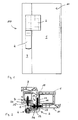
- the designated in the drawing as a whole with 100 embodiment of the tape according to the invention is designed as a so-called two-piece tape. It comprises a wing flap 2 fastened to a wing 1 and a frame hinge flap 4 fastened to a frame 3.
- a multipart strip which has, for example, two spaced-apart frame hinge tabs and a wing hinge flap arranged therebetween in accordance with the invention.
- wing and the frame only multi-chamber hollow sections are shown in the drawing.
- the embodiment is particularly intended for attachment to such hollow sections, but can also be attached to other, for example, solid wings or frame.
- the frame hinge flap is formed in the embodiment shown in the drawing in a conventional manner. It comprises a frame hinge part 5 and a frame fastening part 6 integrally formed thereon, by means of which the frame hinge flap 4 can be fastened to the frame 3 with the aid of frame fastening screws 7 and frame guide bolts 8 (see in particular FIG Fig. 3 ).
- the wing hinge flap 2 comprises a hinge part 9, which is connected to a fastening part 10.
- the hinge and the fastening part are integrally formed (s., In particular 4 and 5 ).
- the front surface 11 of the wing 1 serves in the 8 and 9 It comprises a first bearing leg 13, which is formed in two parts in the illustrated embodiment and comprises a bridge 14 which connects the two parts together.
- a second bearing leg 15 is formed angled at an angle of 90 °.
- two passage openings 16 are provided for a respective first fastening screw 17.
- the holding part 12 is placed on the front surface 11 of the wing, in Fig. 1 to 3 illustrated by a wing profile 1, attached.
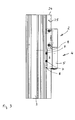
- the first passage openings 16 are arranged such that the first fastening screws 17 can be screwed through two side walls 18 of a Euronut 19, which is provided on an end face 20 of the wing 1.
- second passage openings 21 are provided at the second bearing leg 15 . These serve to pass through a respective second fastening screw 22.
- the distance between the contact side 23 of the second contact leg 15 and the first passage openings 16 is dimensioned such that the second contact leg 15 abuts with the second contact surface 23 on an end face 25 formed by a top 24 ,
- first abutment surface 26 which is formed by the first abutment leg 13
- two cylindrical extensions 27 extend. Each extension has a threaded bore 28.
- the extensions 27 serve to engage in a respective receiving opening 29, the only in Fig. 2 is indicated.
- the holding part 12 comprises on the side facing away from the contact surface 26 side of the bridge 14, a spindle receptacle 30 with a spindle thread 31.
- the fastening part 10 of the wing hinge flap 2 has, on its rear side 32 facing the retaining part 32, grooves 33 in which the two parts of the first abutment leg 13 forming the guide projections 34 are perpendicular to the hinge axis S, i. are moved displaced in the displacement direction. It is adapted to the spindle receptacle 30 and to an adjusting spindle 36 received by this, that both front ends abut the end faces of Verstellspindelage 35, so that during a rotary actuation of the adjusting spindle 36, the fastening part 10 relative to the holding part 12 is displaced in the direction of displacement V.
- two mounting screws 37 are provided, which pass through the fastening part 10 in slot-shaped openings.
- the mounting screws 37 are screwed into the threaded holes 28 of the extensions 27.
- the length of the slot-shaped openings is dimensioned such that a relative displacement between the hinge flap 2 and the fastening part 10 is possible to the desired extent.
- two through openings 38 are provided in the fastening part 10, through which in each case a first fastening screw 17 can be used and tightened approximately at the middle position of the hinge strap 2 relative to the holding part 12 in the first mounting holes 16.
- each threaded hole can also serve for screwing in further fastening screws, which further attachment of the Holding parts - possibly with the interposition of a clamping plate 39 - cause.
Landscapes
- Engineering & Computer Science (AREA)
- Mechanical Engineering (AREA)
- Hinges (AREA)
Applications Claiming Priority (1)
| Application Number | Priority Date | Filing Date | Title |
|---|---|---|---|
| DE202012104306.8U DE202012104306U1 (de) | 2012-11-09 | 2012-11-09 | Band für Türen, Fenster oder dergleichen |
Publications (1)
| Publication Number | Publication Date |
|---|---|
| EP2730732A2 true EP2730732A2 (fr) | 2014-05-14 |
Family
ID=49513803
Family Applications (1)
| Application Number | Title | Priority Date | Filing Date |
|---|---|---|---|
| EP20130190840 Withdrawn EP2730732A2 (fr) | 2012-11-09 | 2013-10-30 | Charnière pour portes, fenêtres ou analogues |
Country Status (3)
| Country | Link |
|---|---|
| EP (1) | EP2730732A2 (fr) |
| DE (1) | DE202012104306U1 (fr) |
| RU (1) | RU2013150108A (fr) |
Cited By (1)
| Publication number | Priority date | Publication date | Assignee | Title |
|---|---|---|---|---|
| GB2574715A (en) * | 2018-05-10 | 2019-12-18 | Ciilock Eng Pty Ltd | Bifold door hinge |
Citations (1)
| Publication number | Priority date | Publication date | Assignee | Title |
|---|---|---|---|---|
| DE29818984U1 (de) | 1998-10-24 | 2000-03-02 | Niemann Hans Dieter | Tür- oder Fensterband |
Family Cites Families (1)
| Publication number | Priority date | Publication date | Assignee | Title |
|---|---|---|---|---|
| DE19732535A1 (de) * | 1997-07-23 | 1999-01-28 | Haps & Sohn Gmbh & Co Kg | Verbesserung an Tür- oder Fensterbändern |
-
2012
- 2012-11-09 DE DE202012104306.8U patent/DE202012104306U1/de not_active Expired - Lifetime
-
2013
- 2013-10-30 EP EP20130190840 patent/EP2730732A2/fr not_active Withdrawn
- 2013-11-08 RU RU2013150108/12A patent/RU2013150108A/ru not_active Application Discontinuation
Patent Citations (1)
| Publication number | Priority date | Publication date | Assignee | Title |
|---|---|---|---|---|
| DE29818984U1 (de) | 1998-10-24 | 2000-03-02 | Niemann Hans Dieter | Tür- oder Fensterband |
Cited By (2)
| Publication number | Priority date | Publication date | Assignee | Title |
|---|---|---|---|---|
| GB2574715A (en) * | 2018-05-10 | 2019-12-18 | Ciilock Eng Pty Ltd | Bifold door hinge |
| GB2574715B (en) * | 2018-05-10 | 2020-06-03 | Ciilock Eng Pty Ltd | Bifold door hinge |
Also Published As
| Publication number | Publication date |
|---|---|
| DE202012104306U1 (de) | 2014-02-10 |
| RU2013150108A (ru) | 2015-05-20 |
Similar Documents
| Publication | Publication Date | Title |
|---|---|---|
| EP0761130B1 (fr) | Ferrure de fixation pour panneaux frontaux de tiroir | |
| DE4219681C2 (de) | Einstellbares Abhebescharnier | |
| EP2873792B1 (fr) | Penture | |
| EP2725174B1 (fr) | Module de charnière | |
| EP3103948B1 (fr) | Penture pour une porte ou une fenêtre | |
| DE202007003675U1 (de) | Vorrichtung zur Befestigung von Beschlagteilen an Hohlprofilen | |
| EP2345786B1 (fr) | Penture de porte pour portes en aluminium | |
| DE102015111308B3 (de) | Rollenband, insbesondere für Kunststofftüren und Kunststofffenster | |
| EP1915498B1 (fr) | Systeme a profile et a bande | |
| DE202015100200U1 (de) | Bandlappenanordnung eines Bandes | |
| EP2400091B1 (fr) | Penture de porte pour le montage sur des systèmes de chambres creuses | |
| DE102009020626B3 (de) | Bandbefestigungsteil | |
| EP2345787B1 (fr) | Penture de porte pour portes en aluminium | |
| EP2730732A2 (fr) | Charnière pour portes, fenêtres ou analogues | |
| DE202008016071U1 (de) | Band zur scharniergelenkigen Verbindung eines Flügels an einem Rahmen | |
| EP3029241A1 (fr) | Ferrure d'angle à force de serrage accrue | |
| EP3814593A1 (fr) | Ensemble d'une bande pour une liaison articulée avec charnière autour d'un axe de charnière d'un battant sur un cadre ainsi que bande pourvue de cet ensemble | |
| DE202010000291U1 (de) | Bandlappenanordnung | |
| DE102018101285A1 (de) | Eckverbinder | |
| EP2514892B1 (fr) | Système de fixation d'une partie de ferrure | |
| DE202005014093U1 (de) | Band für Türen, Fenster o.dgl. | |
| EP0945574B1 (fr) | Charnière pour portes, fenêtres ou similaires | |
| DE2445149A1 (de) | Bandbefestigung, insbesondere eines tuerbandes | |
| EP3121356A1 (fr) | Agencement d'une charnière sur un profilé à cavité creuse | |
| DE202012100927U1 (de) | Bandanordnung zur um eine Scharnierachse scharniergelenkigen Verbindung eines Flügels mit einem Rahmen |
Legal Events
| Date | Code | Title | Description |
|---|---|---|---|
| PUAI | Public reference made under article 153(3) epc to a published international application that has entered the european phase |
Free format text: ORIGINAL CODE: 0009012 |
|
| 17P | Request for examination filed |
Effective date: 20131030 |
|
| AK | Designated contracting states |
Kind code of ref document: A2 Designated state(s): AL AT BE BG CH CY CZ DE DK EE ES FI FR GB GR HR HU IE IS IT LI LT LU LV MC MK MT NL NO PL PT RO RS SE SI SK SM TR |
|
| AX | Request for extension of the european patent |
Extension state: BA ME |
|
| STAA | Information on the status of an ep patent application or granted ep patent |
Free format text: STATUS: THE APPLICATION IS DEEMED TO BE WITHDRAWN |
|
| 18D | Application deemed to be withdrawn |
Effective date: 20160503 |