EP2730537B1 - Zapfkopf aus faserverstärktem Kunststoff - Google Patents
Zapfkopf aus faserverstärktem Kunststoff Download PDFInfo
- Publication number
- EP2730537B1 EP2730537B1 EP13190621.6A EP13190621A EP2730537B1 EP 2730537 B1 EP2730537 B1 EP 2730537B1 EP 13190621 A EP13190621 A EP 13190621A EP 2730537 B1 EP2730537 B1 EP 2730537B1
- Authority
- EP
- European Patent Office
- Prior art keywords
- tap head
- handle
- head body
- tap
- plunger
- Prior art date
- Legal status (The legal status is an assumption and is not a legal conclusion. Google has not performed a legal analysis and makes no representation as to the accuracy of the status listed.)
- Not-in-force
Links
- 229920002430 Fibre-reinforced plastic Polymers 0.000 title claims description 13
- 239000011151 fibre-reinforced plastic Substances 0.000 title claims description 13
- 229920003023 plastic Polymers 0.000 claims description 14
- 239000004033 plastic Substances 0.000 claims description 14
- 235000013361 beverage Nutrition 0.000 claims description 11
- 229920002647 polyamide Polymers 0.000 claims description 11
- 239000004952 Polyamide Substances 0.000 claims description 10
- 239000000835 fiber Substances 0.000 claims description 9
- 230000007246 mechanism Effects 0.000 claims description 6
- 230000008878 coupling Effects 0.000 claims description 5
- 238000010168 coupling process Methods 0.000 claims description 5
- 238000005859 coupling reaction Methods 0.000 claims description 5
- 230000007062 hydrolysis Effects 0.000 claims description 3
- 238000006460 hydrolysis reaction Methods 0.000 claims description 3
- 238000002347 injection Methods 0.000 claims description 3
- 239000007924 injection Substances 0.000 claims description 3
- 238000007789 sealing Methods 0.000 claims description 3
- 238000004023 plastic welding Methods 0.000 claims description 2
- -1 polybutylene terephthalate Polymers 0.000 claims description 2
- 229920001707 polybutylene terephthalate Polymers 0.000 claims description 2
- 239000007789 gas Substances 0.000 claims 4
- 238000004026 adhesive bonding Methods 0.000 claims 1
- 239000000463 material Substances 0.000 description 12
- 238000004519 manufacturing process Methods 0.000 description 6
- 238000000034 method Methods 0.000 description 4
- 230000008569 process Effects 0.000 description 4
- 230000008901 benefit Effects 0.000 description 3
- 238000003825 pressing Methods 0.000 description 3
- 238000010079 rubber tapping Methods 0.000 description 3
- 239000011152 fibreglass Substances 0.000 description 2
- 239000003365 glass fiber Substances 0.000 description 2
- 238000001746 injection moulding Methods 0.000 description 2
- 239000007769 metal material Substances 0.000 description 2
- 239000002994 raw material Substances 0.000 description 2
- 230000002787 reinforcement Effects 0.000 description 2
- 239000000565 sealant Substances 0.000 description 2
- 238000007493 shaping process Methods 0.000 description 2
- 229920002748 Basalt fiber Polymers 0.000 description 1
- 229920000049 Carbon (fiber) Polymers 0.000 description 1
- 230000004913 activation Effects 0.000 description 1
- 239000000853 adhesive Substances 0.000 description 1
- 230000001070 adhesive effect Effects 0.000 description 1
- 235000013334 alcoholic beverage Nutrition 0.000 description 1
- 239000004760 aramid Substances 0.000 description 1
- 229920006231 aramid fiber Polymers 0.000 description 1
- 230000000903 blocking effect Effects 0.000 description 1
- 239000004917 carbon fiber Substances 0.000 description 1
- 238000005266 casting Methods 0.000 description 1
- 238000004891 communication Methods 0.000 description 1
- 230000001419 dependent effect Effects 0.000 description 1
- 230000000994 depressogenic effect Effects 0.000 description 1
- 210000003746 feather Anatomy 0.000 description 1
- 239000012530 fluid Substances 0.000 description 1
- 210000005224 forefinger Anatomy 0.000 description 1
- 239000011521 glass Substances 0.000 description 1
- 238000010348 incorporation Methods 0.000 description 1
- 238000003780 insertion Methods 0.000 description 1
- 230000037431 insertion Effects 0.000 description 1
- 238000009434 installation Methods 0.000 description 1
- 238000005304 joining Methods 0.000 description 1
- 238000003754 machining Methods 0.000 description 1
- 239000002184 metal Substances 0.000 description 1
- 235000019520 non-alcoholic beverage Nutrition 0.000 description 1
- 238000012805 post-processing Methods 0.000 description 1
- 238000012545 processing Methods 0.000 description 1
- 239000003380 propellant Substances 0.000 description 1
- 239000011265 semifinished product Substances 0.000 description 1
- 238000005476 soldering Methods 0.000 description 1
- 230000006641 stabilisation Effects 0.000 description 1
- 238000011105 stabilization Methods 0.000 description 1
- 210000003813 thumb Anatomy 0.000 description 1
- 238000003466 welding Methods 0.000 description 1
Images




Classifications
-
- B—PERFORMING OPERATIONS; TRANSPORTING
- B67—OPENING, CLOSING OR CLEANING BOTTLES, JARS OR SIMILAR CONTAINERS; LIQUID HANDLING
- B67D—DISPENSING, DELIVERING OR TRANSFERRING LIQUIDS, NOT OTHERWISE PROVIDED FOR
- B67D1/00—Apparatus or devices for dispensing beverages on draught
- B67D1/08—Details
- B67D1/0829—Keg connection means
- B67D1/0831—Keg connection means combined with valves
- B67D1/0832—Keg connection means combined with valves with two valves disposed concentrically
Definitions
- the present invention relates to a tap head for connection to a barrel according to the features in the preamble of claim 1.
- Beverage dispensing systems are known from the prior art.
- drinks for example in the form of non-alcoholic or alcoholic beverages in containers, especially provided in barrels.
- the drinks are thus from a filling station to a gas station, for example, in a tavern, in sizes of barrels between 10 to 150 liters conveyed.
- a gas station for example, in a tavern
- barrels between 10 to 150 liters conveyed.
- Schankanalagen are used in order to transport the drink from the keg into a glass.
- a tap head is placed on a barrel and then pushed by pressing a locking mechanism, a plunger towards the barrel. As a result, the tap head is connected to the barrel.
- a clamping gas which is also known as propellant, transferred from the clamping gas tank in the tap head, passed from the tap head into the barrel and thereby generates such an overpressure in the barrel in that the beverage is conveyed from a beverage discharge line of the dispensing head to the dispensing system.
- a dispensing head is for example from the DE 412 817 A1 known.
- a tap for KEG fittings known, which is made of a plastic. Integrally connected to the tap head is a spring tongue with which an actuating lever can be locked. At an overpressure, the tap head is designed such that the material gives way and thus the tap head serves as a pressure relief valve.
- Object of the present invention is to produce a well-known from the prior art tap head significantly cheaper and at the same time sufficiently robust.
- the tap head according to the invention for connection to a keg, in particular for a dispensing system, wherein the tap head has a tap body and in the tap head body a clamping gas supply line and a Getränkeeabloom Gustav are formed and in the tap head body, a movable plunger is arranged, wherein on the tap head body, a pivotable handle is arranged and the handle is kinematically coupled to the plunger, is characterized in that the tap body is made of the same material and in one piece of a fiber-reinforced plastic.
- the tap head according to the invention is thus characterized in particular by the fact that it requires only a few components in order to fulfill its function.
- An essential advantage of the invention is that the tap body itself is designed without sacrificing strength and with the same life expectancy and mechanical properties of a glass fiber reinforced plastic, in particular of a glass fiber reinforced polyamide.
- This offers the advantage that over the prior art known ZapfkopfMechn, which are formed of metallic materials, a high freedom of shaping is provided, at the same time significantly cheaper production costs, on the one hand in the provision of the raw material, on the other hand in the production or production of the Zapfkopf emotionss.
- the tap body can be welded or glued in the context of the invention from several material-uniform parts, so that it is in one piece after completion of the joining process.
- the handle is then attached to the tap head body, the plunger inserted and the supply and discharge lines mounted, with simultaneous incorporation of various sealants.
- span gas line which has a pressure of 0.1 bar to 10 bar, in particular from 0.5 to 7.8 bar and more preferably from 0.6 to 3.7 bar.
- the tap head according to the invention it is possible with the tap head according to the invention to pass gas for all common beverage types.
- the tapping head body according to the invention is produced in particular as a plastic pointed casting component, the fiber fraction of the fiber-reinforced plastic in particular being between 5 and 45%, more preferably between 10 and 40% and very particularly preferably from 15 to 35%, very particularly preferably 25 to 35%.
- the plastic, in particular the polyamide is to be selected as food-grade material, in particular hydrolysis resistant. This makes it possible that the material meets the safety requirements of pressure-carrying and pressure-conducting components due to the good and high resistance strength properties. Due to the simultaneous food authenticity and the hydrolysis stabilization, it is also ensured that the beverage-dispensing tap meets the requirements of the certification for the food industry.
- the fiber-reinforced plastic in particular glass fibers.
- carbon fibers, aramid fibers, basalt fibers and / or metal fibers as fiber reinforcement in the plastic.
- the fibers may be formed as a roving or fiber bundles and are preferably wound around the main body.
- the fibers can also be introduced as short fiber pieces, preferably directly in a plastic injection process.
- the fiber-reinforced plastic has the following mechanical properties, in particular an elongation at break of between 100 and 300 MPa, particularly preferably an elongation at break of 150 to 250 MPa. Furthermore, it is advantageous if the fiber-reinforced plastic has a tensile modulus of 8000 to 12000 MPa, in particular 9000 to 11000 MPa. In particular, the fiber-reinforced plastic furthermore has a density between 1000 and 1500 kg / m 3 , preferably between 1300 and 1400 kg / m 3 . Furthermore, it is advantageous if the glass-reinforced plastic has a processing shrinkage in the flow direction of 0.3 to 1.3% to 2 mm and transversely to the flow direction of 0.9 to 1.3%, in particular from 1.0 to 1.2% 2mm.
- the pivotable handle on the tap head body can be transferred from a starting position into a locking position, wherein the handle in the locking position can be locked to the tap head body itself via an automatic locking mechanism located in the handle.
- the plunger is at least partially moved into the barrel in the axial direction, whereby on the one hand the span gas line with the barrel and on the other hand the barrel is brought into fluid communication with the beverage removal.
- At least one return spring is incorporated, which transfers the handle in the direction of the starting position upon release of the automatic latching. This ensures that the handle assumes no unwanted misalignment and thus it can lead to an uncontrolled leakage of span gas, especially of CO2 or even from the drink.
- span gas especially of CO2 or even from the drink.
- the handle in the direction of the starting position most preferably transferred to the starting position, so that the plunger closes the Spanngaszu ebooktechnischtechnisch in the Zapfkopf stresses gas-tight relative to the environment.
- two unlocking pawls are provided on the handle, wherein the automatic latching system can be unlocked by operating at least one unlocking pawl.
- the unlocking pawls are in particular in such a context that both the one, and the other Entriegelungsklinke are independently operable and in each case by pressing one or the other release latch, the automatic locking system is unlocked.
- the automatic latching is unlocked even with simultaneous activation of both unlocking pawls, even when pressing the two release latches with different intensity. It makes handleability easier, since the tap head can be operated by right-handed and left-handed people, as well as easily accessible in complicated installation situations by an applying mechanic and the automatic locking system can be unlocked.
- an unlocking pawl is arranged on a respective side surface of the handle, so that at least one unlocking pawl can be easily reached by a forefinger or by a thumb when grasping the handle with one hand by an applying mechanic.
- the plunger is integrally formed and made of a plastic material, in particular of a fiber-reinforced plastic, most preferably of a fiber-reinforced polyamide, wherein between the plunger and the tap body at least one sealant is incorporated.
- Plungers known from the prior art are formed exclusively from metallic materials, wherein for the production of the plungers, raw material and / or semifinished products which have different cross sections from each other are required. These are then elaborately preprocessed and coupled together, for example, by a soldering or welding process, or are also compacted or screwed.
- the plunger as a separate component of the Zapfkopf emotions, but for itself material uniformly and in one piece from a Plastic, in particular made of a fiber-reinforced plastic, most preferably formed of a fiber-reinforced polyamide, it is possible to produce this by injection molding.
- a Plastic in particular made of a fiber-reinforced plastic, most preferably formed of a fiber-reinforced polyamide.
- the injection molding process also allows high freedom of shaping freedom, which is why the plunger is optimally adapted to the Zapfkopf emotions.
- the plunger itself is then kinematically coupled within the scope of the invention with the pivotable handle, so that the plunger inserted into the tap body performs a movement in the axial direction.
- connection piece for coupling with the Spanngaszu111 Gustav, wherein the connection piece is made as a separate component, in particular of a plastic, very particularly preferably of a polyamide and in particular of a fiber-reinforced Plastic and particularly preferably made of a fiber-reinforced polyamide, wherein the connecting piece is then coupled cohesively to the Zapfkopf emotions.
- the cohesive coupling takes place by an adhesive process and / or by a plastic welding process.
- connection options on the market are half inch, five-inch or three-tenth thread, wherein the connection options can be formed both male and female, thus having an external thread or an internal thread.
- the connecting piece is then coupled to the tap head body, in particular coupled in a gas-tight manner, wherein the coupling takes place, in particular, as a material fit.
- the connecting pieces can be made separately from the tap body first and then be adapted to the respective customer specifications of the tap head by coupling of connecting pieces with the tap body.
- an inner lateral surface, in particular a cylindrical cavity, which serves as a running surface of the movable tappet is formed in the tapping head body itself.
- a mean roughness RA of the tread is particularly preferably less than or equal to 1.6 ⁇ m, more preferably between 0.6 ⁇ m and 0.1 ⁇ m. This forms in the context of the invention, an optimal relationship between simple movement of the plunger, optimal sealing of the seals located on the plunger and longevity of the tap head.
- the plastic preferably has an E-modulus between 8,000 MPa and 12,000 MPa, in particular between 9,000 MPa and 11,000 MPa, and very particularly preferably between 9,500 MPa and 10,500 MPa.
- the elongation at break is furthermore preferably between 2% and 4% and in particular between 2.5% and 3.5%.
- the plastic furthermore has an impact resistance at minus 30 ° C. between 60 kJ / m 2 and 100 kJ / m 2 , in particular between 65 kJ / m 2 and 80 kJ / m 2 and very particularly from 70 kJ / m 2 to 75 kJ / m 2 up.
- the aforementioned material specifications in conjunction with the fiber reinforcement a tap head is provided that meets the pressure and sealing requirements of beverage manufacturers and legally prescribed pressure and tightness requirement and at the same time offers the possibility to ensure the requirements of food safety.
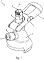
- FIG. 1 shows a tap head 1 according to the invention in a perspective view.
- the tap head 1 in this case has a tap head body 2, wherein a handle 3 is arranged pivotably on the tap head body 2. On the handle 3 unlocking 4 are formed, which allow unlocking a not shown detent automatic.
- a plunger 5 is arranged, which is movable relative to the Zapfkopfmaschine 2 in the axial direction A.
- a connection piece 6 for a span gas line not shown is arranged on the Zapfkopf emotions 2.
- the clamping gas then flows into a barrel and pushes a drink through the plunger 5 via a beverage discharge line 8 from the barrel in the direction of the dispensing system.
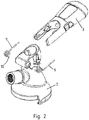
- FIG. 2 shows the tap head body 2 with handle 3 in an exploded view, it being understood that between the handle 3 and the tap head body 2, two springs 9 are incorporated.
- the springs 9 are locked on the one hand with an extension in the Zapfkopf Sciences 2 not shown in detail and practice on depression of the handle 3 from the in FIG. 1 illustrated starting position such a spring force from that the handle 3 is again transported back in the direction of the starting position. An accidentally depressed handle 3 thus does not lead to an outflow of the clamping gas.
- FIG. 3a shows a cross-sectional view through the tap head according to the invention 1.
- the plunger 5 and the tap head body 2 are two mutually different components, but which are each formed in one piece and material uniform.
- the plunger 5 is moved in the axial direction A drawn on the image plane downwards and thus at least partially comes into engagement with a lower end 11 in a not-shown barrel.
- Tension gas can then enter the drum via the tension gas supply line 7 and the beverage located in the drum can be removed via the beverage discharge line 8 of the tappet 5 to the dispenser. So that the handle 3 in the in FIG. 3 shown starting position but also in an in FIG.
- Locking position not shown can be locked, the unlocking pawls have a locking extension 12, wherein the locking extension 12 comes into engagement in a respective recess 13 on the Zapfkopf stresses 2 and locked there.
- the handle 3 By actuating at least one unlocking pawl, it is possible to extract the locking extension 12 from the recess and through the in FIG. 2 shown springs, the handle 3 always moves in the pivoting direction back to the in FIG. 3a shown starting position back.
- FIG. 3b shows the same sectional view as FIG. 3a , with the difference that the handle 3 is brought into a shut-off position or locking position.
- the plunger 5 is extended relative to the Zapfkopfköper 2 in the axial direction A down.
- the unlocking pawl 4 is engaged in the lower recess 13.
- the lower seal 14 is thereby extended out of the lower cylindrical surface 15 of the Zapfkopf stressess 2, that the clamping gas can flow along the plunger in the barrel, not shown.
- FIG. 3b This has particularly preferably the average roughness RA described above, so that jamming and locking of the plunger 5 is avoided, while high accuracy of fit and good stick-slip behavior of the corresponding seals 14th , 23 as they slide over the tread 22.
- FIG. 4 shows a further aspect of the present invention. It is possible to use a respective connecting piece 6 in the tap head body 2 and to be welded or glued thereto. This makes it possible to produce the Zapfkopfköper 2 as a single component in larger quantities, thereby reducing production costs and then by respective choice of the connecting piece 6, for example, with external thread or internal thread to assemble such that it meets customer requirements.
- a respective connecting piece 6 has an extension 16, in particular a cylindrical shape, which is at least partially inserted into a receiving opening 17 of the Zapfkopf stresses 2 and then glued and / or welded in this.
- the connecting piece 6 is formed from the same material, from which also the tap head body 2 is formed.
- FIGS. 5a to d further explains the operating principle of the release pawls. So is in the FIG. 5a a top view of the dispensing head 1 according to the invention, with two each unlocked release pawls 4. According to Figure b and c, it is possible to depress only one unlocking pawl 4, and yet to unlock the locking position. According to FIG. 5d is also possible to depress both unlocking pawls 4 to also unlock the handle 3 from the locking position.
- the two release pawls 4 are kinematically coupled to one another such that the in FIG. 5 Not shown detent mechanism is unlocked both by the related to the image plane left but also right Entriegelungsklinke 4.
- FIG. 6 It also shows the tap head 1 according to the invention in a top view from above in a partial section with a cut handle 3.
- the handle 3 is also of the same material, in particular in one piece, whereby the manufacturing costs and assembly costs are also low fail.
- the handle 3 is formed of fiber-reinforced polyamide.
- Zapfkopfophil 2 cross bolt 19 Between handle 3 and Zapfkopf stresses 2 incorporated is the in FIG. 2 illustrated spring 9, which transfers the handle 3 again in the starting position.
- the handle 3 ram pins 20 which in a in FIG. 3 shown groove 21 of the plunger 5 engage and thus allow the axial movement A of the plunger 5 in carrying out the pivoting movement S of the handle 3.
- the plunger bolts 20 form a positive engagement with the groove 21.
Landscapes
- Devices For Dispensing Beverages (AREA)
- Medical Preparation Storing Or Oral Administration Devices (AREA)
Description
- Die vorliegende Erfindung betrifft einen Zapfkopf zum Anschluss an ein Fass gemäß den Merkmalen im Oberbegriff von Patentanspruch 1.
- Aus dem Stand der Technik sind Getränkeschankanlagen bekannt. Hierzu werden Getränke, beispielsweise in Form von nichtalkoholischen oder aber alkoholischen Getränken in Gebinden, insbesondere in Fässern bereitgestellt. Die Getränke sind somit von einer Abfüllstation zu einer Schankstelle, beispielsweise in einem Wirtshaus, in Größenmengen von Fässern zwischen 10 bis 150 Litern beförderbar. Um nunmehr das Getränk aus dem Fass in ein Glas zu befördern, werden Schankanalagen eingesetzt. Hierzu wird ein Zapfkopf auf ein Fass aufgesetzt und anschließend durch Betätigung eines Verriegelungsmechanismusses ein Stößel in Richtung zu dem Fass geschoben. Hierdurch wird der Zapfkopf an das Fass angeschlossen.
- Damit nunmehr das Getränk aus dem Fass durch den Zapfkopf in die Schankanlage befördert wird, wird ein Spanngas welches auch als Treibgas bekannt ist, aus dem Spanngasbehälter in den Zapfkopf überführt, von dem Zapfkopf in das Fass geleitet und hierdurch ein derartiger Überdruck in dem Fass erzeugt, dass das Getränk aus einer Getränkeabführleitung des Zapfkopfes zu der Schankanlage befördert wird. Wird nunmehr der Schankhahn geöffnet, so strömt das Getränk aus dem Fass aus und das sich entleerende Volumen im Fass wird mit Spanngas aufgefüllt. Ein solcher Zapfkopf ist beispielsweise aus der
DE 412 817 A1 bekannt. - Aus der
DE 43 03 461 C1 ist ein Zapfkopf für KEG-Armaturen bekannt, der aus einem Kunststoff hergestellt wird. Einstückig verbunden mit dem Zapfkopf ist eine Federzunge, mit der ein Betätigungshebel arretiert werden kann. Bei einem Überdruck ist der Zapfkopf derart ausgebildet, dass der Werkstoff nachgibt und somit der Zapfkopf als Überdruckventil dient. - Aufgabe der vorliegenden Erfindung ist es, einen aus dem Stand der Technik bekannten Zapfkopf deutlich kostengünstiger und zugleich ausreichend robust herzustellen.
- Die zuvor genannte Aufgabe wird erfindungsgemäß mit den Merkmalen gemäß Patentanspruch 1 gelöst. Vorteilhafte Ausführungsvarianten sind Gegenstand der abhängigen Patentansprüche.
- Der erfindungsgemäße Zapfkopf zum Anschluss an ein Fass, insbesondere für eine Schankanlage, wobei der Zapfkopf einen Zapfkörper aufweist und in dem Zapfkopfkörper eine Spanngaszufuhrleitung und eine Getränkeabführleitung ausgebildet sind und in den Zapfkopfkörper ein beweglicher Stößel angeordnet ist, wobei an dem Zapfkopfkörper ein schwenkbarer Griff angeordnet ist und der Griff mit dem Stößel kinematisch gekoppelt ist, ist dadurch gekennzeichnet, dass der Zapfkopfkörper werkstoffeinheitlich und einstückig aus einem faserverstärktem Kunststoff ausgebildet ist.
- Der erfindungsgemäße Zapfkopf zeichnet sich somit insbesondere dadurch aus, dass er nur wenige Bauteile benötigt, um seine Funktion zu erfüllen.
- Erfindungswesentlicher Vorteil ist, dass der Zapfkopfkörper selbst, ohne Festigkeitseinbußen und bei gleicher Lebensdauererwartung und mechanischen Eigenschaften aus einem glasfaserverstärktem Kunststoff, insbesondere aus einem glasfaserverstärktem Polyamid ausgebildet ist. Hierdurch bietet sich der Vorteil, dass gegenüber dem Stand der Technik bekannten Zapfkopfkörpern, welche aus metallischen Werkstoffen ausgebildet sind eine hohe Formgebungsfreiheit bereitgestellt wird, bei gleichzeitig deutlich günstigeren Herstellungskosten, zum einen in der Bereitstellung des Rohmaterials, zum anderen in der Herstellung bzw. Fertigung des Zapfkopfkörpers. Der Zapfkopfkörper kann dabei im Rahmen der Erfindung auch aus mehreren werkstoffeinheitlichen Teilen kunststoffgeschweißt oder geklebt sein, so dass er nach Abschluss des Fügevorganges einstückig ist.
- Erfindungsgemäß werden dann an den Zapfkopfkörper der Griff angesetzt, der Stößel eingesetzt sowie die Zu- und Abführleitungen montiert, unter gleichzeitiger Eingliederung von verschiedenen Dichtmitteln.
- Insbesondere wird dabei ein Spanngas durch die Spanngasleitung geführt, welches einen Druck von 0,1 bar bis 10 bar, insbesondere von 0,5 bis 7,8 bar und besonders bevorzugt von 0,6 bis 3,7 bar aufweist. Mithin ist es mit dem erfindungsgemäßen Zapfkopf möglich, Spanngas für alle gängigen Getränketypen durchzuleiten.
- Der erfindungsmäße Zapfkopfkörper wird insbesondere als Kunststoffspitzgussbauteil hergestellt, wobei der Faseranteil des faserverstärkten Kunststoffes insbesondere zwischen 5 und 45% besonders bevorzugt zwischen 10 und 40% und ganz besonders bevorzugt von 15 bis 35% ganz besonders bevorzugt 25 bis 35% beträgt. Der Kunststoff, insbesondere das Polyamid ist als lebensmittelechter Werkstoff zu wählen, insbesondere hydrolysebeständig. Hierdurch wird es ermöglicht, dass der Werkstoff durch die guten und mit hoher Resistenz versehenen Festigkeitseigenschaften den Sicherheitsanforderungen an druckführenden und druckleitenden Bauteilen genügt. Durch die gleichzeitige Lebensmittelechtheit, und die Hydrolysestabilisation ist zudem auch sichergestellt, dass der getränkeleitende Zapfkopf den Anforderungen der Zertifizierung für die Lebensmittelindustrie genügt.
- Weiterhin weist der faserverstärkte Kunststoff insbesondere Glasfasern auf. Im Rahmen der Erfindung ist es jedoch auch möglich Karbonfasern, Aramidfasern, Basaltfasern und/oder Metallfasern als Faserverstärkung in den Kunststoff einzubinden. Die Fasern können dabei als Roving oder Faserbündel ausgebildet sein und bevorzugt um den Grundkörper gewickelt werden. Alternativ können die Fasern auch als kurze Faserstücke eingebracht sein, bevorzugt direkt in einem Kunststoffspritzprozess.
- Weiterhin weist insbesondere der Faserverstärkte Kunststoff nachfolgende mechanische Eigenschaften auf, insbesondere eine Bruchdehnung zwischen 100 und 300 MPa, besonders bevorzugt eine Bruchdehnung von 150 bis 250 MPa. Weiterhin ist es von Vorteil wenn der faserverstärkte Kunststoff ein Zugmodul von 8000 bis 12000 MPa, insbesondere 9000 bis 11000 MPa aufweist. Insbesondere weist der faserverstärkte Kunststoff weiterhin eine Dichte zwischen 1000 und 1500 kg/m3, bevorzugt zwischen 1300 und 1400 kg/m3 auf. Ferner ist es von Vorteil, wenn der glaserverstärkte Kunststoff eine Verarbeitungsschwindung in Fließrichtung von 0,3 bis 1,3% auf 2mm und quer zur Fließrichtung von 0,9 bis 1,3%, insbesondere von 1,0 bis 1,2% auf 2mm aufweist.
- In einer weiteren vorteilhaften Ausführungsvariante der vorliegenden Erfindung ist der schwenkbare Griff an dem Zapfkopfkörper von einer Ausgangsposition in eine Verriegelungsposition überführbar, wobei der Griff in der Verriegelungsposition über eine in dem Griff befindliche Rastautomatik an dem Zapfkopfkörper selbst verriegelbar ist. Hier ist es möglich zunächst den Zapfkopf auf ein Fass aufzusetzen und durch Ausführen der Schwenkbewegung des Griffes den Zapfkopf an dem Fass anzuschließen. Insbesondere wird hierzu der Stößel in axialer Richtung zumindest abschnittsweise in das Fass hinein bewegt, wodurch zum einen die Spanngasleitung mit dem Fass und zum anderen das Fass mit der Getränkeabführleitung in fluidleitende Verbindung gebracht wird.
- Zwischen dem Griff und dem Zapfkopfkörper ist erfindungsgemäß mindestens eine Rückstellfeder eingegliedert, die bei Entriegelung der Rastautomatik den Griff in Richtung der Ausgangsposition überführt. Hierdurch wird sichergestellt, dass der Griff keine ungewollte Fehlstellung einnimmt und es somit zu einem unkontrollierten Austreten von Spanngas, insbesondere von CO2 oder aber auch von dem Getränk kommen kann. Insbesondere bei einem von dem Fass abgekoppelten Zapfkopf, wird somit stets der Griff in Richtung der Ausgangsposition, ganz besonders bevorzugt in die Ausgangsposition überführt, so dass der Stößel die Spanngaszuführleitung in dem Zapfkopfkörper gasdicht gegenüber der Umgebung verschließt. Dies ist ein besonderes Sicherheitsmerkmal, da hierdurch sichergestellt wird, dass kein Spanngas aus dem Zapfkopf unkontrolliert und/oder ungewollt austreten kann.
- In einer weiteren vorteilhaften Ausführungsvariante des erfindungsgemäßen Zapfkopfes sind an dem Griff zwei Entriegelungsklinken vorgesehen, wobei die Rastautomatik durch Betätigen mindestens einer Entriegelungsklinke entriegelbar ist. Die Entriegelungsklinken stehen insbesondere in einem derartigen Wirkzusammenhang, dass sowohl die eine, als auch die andere Entriegelungsklinke unabhängig voneinander betätigbar sind und jeweils durch ein Betätigen der einen oder aber der anderen Entriegelungsklinke die Rastautomatik entriegelt wird. Die Rastautomatik wird jedoch auch bei gleichzeitigem Betätigen beider Entriegelungsklinken, auch bei Betätigen der beiden Entriegelungsklinken mit unterschiedlicher Intensität, entriegelt. Es erleichtet die Handhabbarkeit, da der Zapfkopf somit sowohl für Rechts- als auch Linkshänder gleichsam bedienbar ist, als auch in komplizierten Einbausituationen durch einen anwendenden Monteur leicht erreichbar ist und die Rastautomatik entriegelbar ist. Als besonders bevorzugte Ausführungsvariante ist eine Entriegelungsklinke auf jeweils einer Seitenfläche des Griffs angeordnet, so dass mindestens eine Entriegelungsklinke durch einen Zeigefinger oder durch einen Daumen bei umgreifen des Griffes mit einer Hand durch einen anwendenden Monteur leicht erreichbar ist.
- Als weitere vorteilhafte Ausführungsvariante der vorliegenden Erfindung ist insbesondere auch der Stößel einteilig und werkstoffeinheitlich aus einem Kunststoff ausgebildet, insbesondere aus einem faserverstärkten Kunststoff, ganz besonders bevorzugt aus einem faserverstärkten Polyamid, wobei zwischen dem Stößel und dem Zapfkopfkörper mindestens ein Dichtmittel eingegliedert ist. Aus dem Stand der Technik bekannte Stößel sind ausschließlich aus metallischen Werkstoffen ausgebildet, wobei es zur Fertigung der Stößel Rohmaterial und/oder Halbzeuge bedarf, die voneinander verschiedene Querschnitte aufweisen. Diese werden dann aufwendig vorbearbeitet und miteinander gekoppelt, beispielsweise durch ein Löt- oder aber Schweißverfahren, oder auch verdichtet oder verschraubt sind.
- Durch den erfindungsgemäßen Stößel, der als separates Bauteil von dem Zapfkopfkörper, jedoch für sich werkstoffeinheitlich und einstückig aus einem Kunststoff insbesondere aus einem faserverstärkten Kunststoff, ganz besonders bevorzugt aus einem faserverstärktem Polyamid ausgebildet ist, ist es möglich diesen im Spritzgusverfahren herzustellen. Durch Optimierung der Spritzgußform, kann ebenfalls auf eine Nachbearbeitung, beispielsweise durch ein spanabhebendes Verfahren, verzichtet werden. Das Spritzgußverfahren ermöglicht zugleich hohe Formgebungsfreiheitsgerade, weshalb der Stößel optimal an den Zapfkopfkörper anpassbar ist. Der Stößel selbst ist dann im Rahmen der Erfindung kinematisch mit dem schwenkbaren Griff gekoppelt, so dass der in den Zapfkopfkörper eingesetzte Stößel eine Bewegung in Axialrichtung ausführt.
- In einer weiteren vorteilhaften Ausführungsvariante der vorliegenden Erfindung ist vorgesehen, dass in dem Zapfkopfkörper ein Anschlussstutzen zur Koppelung mit der Spanngaszuführleitung vorgesehen ist, wobei der Anschlussstutzen als separates Bauteil hergestellt ist, insbesondere aus einem Kunststoff, ganz besonders bevorzugt aus einem Polyamid und insbesondere aus einem faserverstärktem Kunststoff und besonders bevorzugt aus einem faserverstärktem Polyamid, wobei der Anschlussstutzen dann mit dem Zapfkopfkörper stoffschlüssig gekoppelt ist. Bevorzugt erfolgt die stoffschlüssige Koppelung durch einen Klebevorgang und/oder durch einen Kunststoffschweißvorgang. Dieses Merkmal ermöglicht es zunächst den Zapfkopfkörper in großer Stückzahl einheitlich herzustellen, wodurch die Kosten pro Stück deutlich gesenkt werden. Gleichzeitig ist es jedoch möglich, verschiedene am Markt befindliche Anschlussmöglichkeiten mit dem Zapfkopfkörper zu koppeln. Beispielsweise sind dies Halbzoll, Fünfachtelzoll oder Dreiachtelzoll Gewinde, wobei die Anschlussmöglichkeiten sowohl männlich als auch weiblich ausgebildet sein können, mithin ein Außengewinde oder aber ein Innengewinde aufweisen können. Hier ist es möglich den Anschlussstutzen als separates Bauteil aus dem bevorzugt gleichen Werkstoff auszubilden, aus dem der Zapfkopfkörper selbst ausgebildet ist. Der Anschlussstutzen wird dann mit dem Zapfkopfkörper gekoppelt, insbesondere gasdicht gekoppelt, wobei die Koppelung insbesondere stoffschlüssig erfolgt. Somit können die Anschlussstutzen separat von dem Zapfkopfkörper zunächst hergestellt werden und im Anschluss daran an die jeweiligen Kundenspezifikationen des Zapfkopfes durch Koppelung von Anschlussstutzen mit dem Zapfkopfkörper angepasst werden.
- Weiterhin besonders bevorzugt ist in dem Zapfkopfkörper selbst eine Innenmantelfläche, insbesondere ein zylindrischer Hohlraum ausgebildet, der als Lauffläche des beweglichen Stößels dient. Besonders bevorzugt ist im Rahmen der Erfindung eine mittlere Rauheit RA der Lauffläche kleiner gleich 1,6 µm, besonders bevorzugt zwischen 0,6 µm und 0,1 µm. Dies bildet im Rahmen der Erfindung einen optimalen Zusammenhang zwischen einfacher Beweglichkeit des Stößels, optimaler Abdichtung der an dem Stößel befindlichen Dichtungen und Langlebigkeit des Zapfkopfes.
- Weiterhin besonders bevorzugt ist der Kunststoff Polyamid oder aber auf Polyamidbasis oder alternativ ein Polybutylenterephthalat bzw. auf dessen Basis ausgebildet.
- Bevorzugt weist der Kunststoff ein E-Modul zwischen 8.000 MPa und 12.000 MPa, insbesondere zwischen 9.000 MPa und 11.000 MPa und ganz besonders bevorzugt zwischen 9.500 MPa und 10.500 MPa auf. Die Bruchdehnung liegt weiterhin bevorzugt zwischen 2 % und 4 % und insbesondere zwischen 2,5 % und 3,5 %. Der Kunststoff weist weiterhin eine Schlagzähigkeit bei minus 30°C zwischen 60 kJ/m2 und 100 kJ/m2, insbesondere zwischen 65 kJ/m2 und 80 kJ/m2 und ganz besonders von 70 kJ/m2 bis 75 kJ/m2 auf. Durch die vorgenannten Werkstoffangaben wird in Verbindung mit der Faserverstärkung ein Zapfkopf bereitgestellt, der die Druck- und Dichtigkeitsanforderungen der Getränkehersteller sowie gesetzlich vorgegebene Druck- und Dichtigkeitsanforderung erfüllt und zugleich die Möglichkeit bietet, die Anforderungen an die Lebensmittelechtheit zu gewährleisten.
- Weitere Vorteile, Merkmale, Eigenschaften und Aspekte der vorliegenden Erfindung sind Bestandteil der nachfolgenden Beschreibung. Bevorzugte Ausführungsvarianten werden in den schematischen Figuren dargestellt. Diese dienen dem einfachen Einverständnis der Erfindung. Es zeigen:
- Figur 1
- einen erfindungsgemäßen Zapfkopf in einer perspektivischen Ansicht,
- Figur 2
- den Zapfkopf in Explosionsdarstellung ohne Stößel,
- Figur 3a und b
- den erfindungsgemäßen Zapfkopf in einer Schnittansicht mit eingesetztem Stößel,
- Figur 4
- den erfindungsgemäßen Zapfkopf mit verschiedenen Anschlussstutzen,
- Figur 5a bis d
- den erfindungsgemäßen Zapfkopf in einer Draufsicht sowie verschiedenen Verriegelungsmöglichkeiten der Entriegelungsklinken und
- Figur 6
- eine Draufsicht auf den erfindungsgemäßen Zapfkopf mit einem Griff in Schnittansicht.
- In den Figuren werden für gleiche oder ähnliche Bauteile dieselben Bezugszeichen verwendet, auch wenn eine wiederholte Beschreibung aus Vereinfachungsgründen entfällt.
-
Figur 1 zeigt einen erfindungsgemäßen Zapfkopf 1 in einer perspektivischen Ansicht. Der Zapfkopf 1 weist dabei einen Zapfkopfkörper 2 auf, wobei an dem Zapfkopfkörper 2 schwenkbar ein Griff 3 angeordnet ist. An dem Griff 3 sind Entriegelungsklinken 4 ausgebildet, die ein Entsperren einer nicht näher dargestellten Rastautomatik ermöglichen. Ferner ist in dem Zapfkopfkörper 2 ein Stößel 5 angeordnet, der in Axialrichtung A relativ zu dem Zapfkopfkörper 2 bewegbar ist. Weiterhin ist an dem Zapfkopfkörper 2 ein Anschlussstutzen 6 für eine nicht näher dargestellte Spanngasleitung angeordnet. Durch den Anschlussstutzen 6 ist es möglich ein Spanngas in den Zapfkopf 1 über eine Spanngaszuführleitung 7 einzuleiten. Das Spanngas strömt dann in ein Fass ein und drückt ein Getränk durch den Stößel 5 über eine Getränkeabführleitung 8 aus dem Fass in Richtung zu der Schankanlage aus. -
Figur 2 zeigt den Zapfkopfkörper 2 mit Griff 3 in Explosivdarstellung, wobei zu erkennen ist, dass zwischen dem Griff 3 und dem Zapfkopfkörper 2 zwei Federn 9 eingegliedert sind. Die Federn 9 sind zum einen mit einem Fortsatz in dem Zapfkopfkörper 2 nicht näher dargestellt arretiert und üben bei Herunterdrücken des Griffes 3 aus der inFigur 1 dargestellten Ausgangsposition eine Federkraft derart aus, dass der Griff 3 wieder in Richtung der Ausgangsposition zurückbefördert wird. Ein versehentlich heruntergedrückter Griff 3 führt somit nicht zu einem Ausströmen des Spanngases. -
Figur 3a zeigt eine Querschnittsansicht durch den erfindungsgemäßen Zapfkopf 1. Hierbei ist gut zu erkennen, dass der Stößel 5 und der Zapfkopfkörper 2 zwei voneinander verschiedene Bauteile sind, die jedoch jeweils einstückig und werkstoffeinheitlich ausgebildet sind. Durch Ausführen einer Schwenkbewegung S des Griffes 3 ist es mithin möglich, dass der Stößel 5 in eingezeichneter Axialrichtung A auf die Bildebene bezogen nach unten bewegt wird und somit mit einem unteren Ende 11 in ein nicht näher dargestelltes Fass zumindest teilweise zum Eingriff kommt. Über die Spanngaszuführleitung 7 kann dann Spanngas in das Fass eintreten und das in dem Fass befindliche Getränk über die Getränkeabführleitung 8 des Stößels 5 zu der Zapfanlage abgeführt werden. Damit der Griff 3 in der inFigur 3 dargestellten Ausgangsposition aber auch in einer inFigur 3 nicht dargestellten Verriegelungsposition arretierbar ist, weisen die Entriegelungsklinken einen Sperrfortsatz 12 auf, wobei der Sperrfortsatz 12 in eine jeweilige Ausnehmung 13 an dem Zapfkopfkörper 2 zum Eingriff kommt und dort verriegelt. Durch Betätigung mindestens einer Entriegelungsklinke ist es möglich den Sperrfortsatz 12 aus der Ausnehmung herauszuziehen und durch die inFigur 2 dargestellten Federn bewegt sich der Griff 3 immer in Schwenkrichtung wieder zu der inFigur 3a dargestellten Ausgangsposition zurück. Mindestens jedoch wird immer eine untere Dichtung 14 des Stößels 5 derart in den Zapfkopfkörper 2 eingefahren, dass sie gasdicht mit einer unteren Zylinderfläche 15 des Zapfkopfkörpers 2 zur Anlage kommt, so dass kein Spanngas über die Spanngaszuführleitung 7 in das Fass oder die Umgebung entweichen kann. -
Figur 3b zeigt die gleiche Schnittansicht wieFigur 3a , mit dem Unterschied, dass der Griff 3 in eine Absperrposition bzw. Verriegelungsposition gebracht ist. Der Stößel 5 ist dabei relativ gegenüber dem Zapfkopfköper 2 in Axialrichtung A nach unten ausgefahren. Die Entriegelungsklinke 4 ist in die untere Ausnehmung 13 eingerastet. Die untere Dichtung 14 ist dabei derart aus der unteren Zylinderfläche 15 des Zapfkopfkörpers 2 ausgefahren, dass das Spanngas entlang des Stößels in das nicht näher dargestellte Fass strömen kann. - Ferner ist in
Figur 3b dargestellt die innere Lauffläche 22 für den beweglichen Stößel 5. Diese weist besonders bevorzugt die zuvor beschriebene mittlere Rauheit RA auf, so dass ein Verklemmen und Verrasten des Stößels 5 vermieden ist, bei gleichzeitiger hoher Passgenauigkeit und gutem Stick-Slip-Verhalten der entsprechenden Dichtungen 14, 23, wenn diese über die Lauffläche 22 gleiten. -
Figur 4 zeigt einen weiteren Aspekt der vorliegenden Erfindung. Es ist möglich einen jeweiligen Anschlussstutzen 6 in den Zapfkopfkörper 2 einzusetzen und mit diesem zu verschweißen oder zu verkleben. Hierdurch ist es möglich den Zapfkopfköper 2 als einheitliches Bauteil in größerer Stückzahl herzustellen, wodurch die Produktionskosten sinken und dann durch jeweilige Wahl des Anschlussstutzens 6 beispielsweise mit Außengewinde oder aber Innengewinde derart zu konfektionieren, dass er den Kundenwünschen entspricht. Hierzu weist ein jeweiliger Anschlussstutzen 6 einen Fortsatz 16, insbesondere zylinderförmig auf, der in eine Aufnahmeöffnung 17 des Zapfkopfkörpers 2 zumindest teilweise eingeführt wird und dann in diesem verklebt und/oder verschweißt wird. Insbesondere ist der Anschlussstutzen 6 aus dem gleichen Werkstoff ausgebildet, aus dem auch der Zapfkopfkörper 2 ausgebildet ist. -
Figur 5a bis d erläutert weiterhin das Funktionsprinzip der Entriegelungsklinken. So ist in derFigur 5a eine Draufsicht auf den erfindungsgemäßen Zapfkopf 1 gezeigt, mit zwei jeweils ausgefahrenen Entriegelungsklinken 4. Gemäß Figur b und c ist es möglich jeweils nur eine Entriegelungsklinke 4 einzudrücken, und dennoch die Arretierposition zu entriegeln. GemäßFigur 5d ist ebenfalls möglich, beide Entriegelungsklinken 4 einzudrücken um ebenfalls den Griff 3 aus der Arretierposition zu entriegeln. Hierzu sind die beiden Entriegelungsklinken 4 kinematisch untereinander derart gekoppelt, dass der inFigur 5 nicht näher dargestellte Rastmechanismus sowohl durch die auf die Bildebene bezogene linke aber auch rechte Entriegelungsklinke 4 jeweils entriegelbar ist. -
Figur 6 zeigt weiterhin den erfindungsgemäßen Zapfkopf 1 in einer Draufsicht von oben in einem Teilschnitt mit geschnittenem Griff 3. Gut zu erkennen ist, dass der Griff 3 ebenfalls werkstoffeinheitlich, insbesondere einstückig ausgebildet ist, wodurch auch wiederrum die Herstellungskosten sowie die Montagekosten gering ausfallen. Bevorzugt ist auch der Griff 3 aus faserverstärktem Polyamid ausgebildet. So ist es durch Einführschrägen 18 an dem Griff 3 möglich, diesen auf einstückig an dem Zapfkopfkörper 2 ausgebildeten Querbolzen 19 formschlüssig, jedoch drehbar, zu arretieren. Zwischen Griff 3 und Zapfkopfkörper 2 eingegliedert ist die inFigur 2 dargestellte Feder 9, die den Griff 3 immer wieder in die Ausgangsposition überführt. Ferner weist der Griff 3 Stößelbolzen 20 auf, die in eine inFigur 3 dargestellte Nut 21 des Stößels 5 eingreifen und somit die Axialbewegung A des Stößels 5 bei Ausführen der Schwenkbewegung S des Griffes 3 ermöglichen. Mithin bilden die Stößelbolzen 20 mit der Nut 21 einen formschlüssigen Eingriff. -
- 1 -
- Zapfkopf
- 2 -
- Zapfkopfkörper
- 3 -
- Griff
- 4 -
- Entriegelungsklinken
- 5 -
- Stößel
- 6 -
- Anschlussstutzen
- 7 -
- Spanngaszuführleitung
- 8 -
- Getränkeabführleitung
- 9 -
- Feder
- 10 -
- Fortsatz
- 11 -
- unteres Ende zu 5
- 12 -
- Sperrfortsatz
- 13 -
- Ausnehmung
- 14 -
- untere Dichtung zu 5
- 15 -
- untere Zylinderfläche
- 16 -
- zylinderförmige Fortsatz
- 17 -
- Aufnahmeöffnung
- 18 -
- Einführschräge
- 19 -
- Querbolzen
- 20 -
- Stößelbolzen
- 21 -
- Nut zu 5
- 22 -
- Lauffläche
- 23 -
- Dichtung
- A -
- Axialrichtung
- S -
- Schwenkbewegung
- RA -
- Rauheit
Claims (10)
- Zapfkopf (1) zum Anschluss an ein Fass, insbesondere für eine Schankanlage, wobei der Zapfkopf (1) einen Zapfkopfkörper (2) aufweist und in dem Zapfkopfkörper (2) eine Spanngaszuführleitung (7) und eine Getränkeabführleitung (8) ausgebildet sind und in dem Zapfkopfkörper (2) ein beweglicher Stößel (5) angeordnet ist, wobei an dem Zapfkopfkörper (2) ein schwenkbarer Griff (3) angeordnet ist und der Griff (3) mit dem Stößel (5) kinematisch gekoppelt ist, dadurch gekennzeichnet, dass der Zapfkopfkörper (2) werkstoffeinheitlich und einstückig aus einem faserverstärkten Kunststoff ausgebildet ist.
- Zapfkopf nach Anspruch 1, dadurch gekennzeichnet, dass Spanngase durch die Spanngasleitung führbar sind, die einen Druck von 0,01 bis 10 bar, insbesondere von 0,5 bis 7,8 bar, besonders bevorzugt von 0,6 bis 3,7 bar aufweisen.
- Zapfkopf nach Anspruch 1 oder 2, dadurch gekennzeichnet, dass der Zapfkopfkörper (2) als Spritzgussbauteil ausgebildet ist, insbesondere mit einem Faseranteil zwischen 5 und 45%, bevorzugt zwischen 10 und 40%, besonders bevorzugt von 15 bis 30%.
- Zapfkopf nach einem der vorangehenden Ansprüche, dadurch gekennzeichnet, dass der Kunststoff hydrolysestabilisiert ist und insbesondere eine Bruchdehnung zwischen 100 und 300MPa, insbesondere 150 bis 250MPa aufweist.
- Zapfkopf nach einem der vorangehenden Ansprüche, dadurch gekennzeichnet, dass der schwenkbare Griff (3) von einer Ausgangsposition in eine Verriegelungsposition überführbar ist, wobei der Griff (3) in der Verriegelungsposition über eine in dem Griff (3) befindliche Rastautomatik an dem Zapfkopfkörper (2) verriegelbar ist, wobei mindestens eine Rückstellfeder (9) zwischen dem Griff (3) und dem Zapfkopfkörper (2) eingegliedert ist, die bei Entriegelung der Rastautomatik den Griff (3) in Richtung der Ausgangsposition überführt.
- Zapfkopf nach einem der vorangehenden Ansprüche, dadurch gekennzeichnet, dass an dem Griff (3) zwei Entriegelungsklinken (4) vorgesehen sind, wobei die Rastautomatik durch Betätigen mindestens einer Entriegelungsklinke (4) entriegelbar ist, insbesondere ist jeweils eine Entriegelungsklinke (4) auf jeder Seite des Griffes (3) angeordnet.
- Zapfkopf nach einem der vorangehenden Ansprüche, dadurch gekennzeichnet, dass der Stößel (5) einteilig und werkstoffeinheitlich aus einem Kunststoff ausgebildet ist, insbesondere aus einem faserverstärktem Kunststoff, bevorzugt aus einem faserverstärktem Polyamid, wobei zwischen dem Stößel (5) und dem Zapfkopfkörper (2) mindestens ein Dichtmittel (14) eingegliedert ist.
- Zapfkopf nach einem der vorangehenden Ansprüche, dadurch gekennzeichnet, dass an dem Zapfkopfkörper (2) ein Anschlussstutzen (6) zur Koppelung mit einer Spanngaszuführleitung (7) vorgesehen ist, wobei der Anschlussstutzen (6) als separates Bauteil hergestellt ist, insbesondere aus Kunststoff, und mit dem Zapfkopfkörper (2) stoffschlüssig gekoppelt ist, bevorzugt durch Kleben und/oder Kunststoffschweißen.
- Zapfkopf nach einem der vorangehenden Ansprüche, dadurch gekennzeichnet, dass in dem Zapfkopfkörper (2) eine Innenmantelfläche als Lauffläche (22) für den beweglichen Stößel (5) ausgebildet ist, wobei die mittlere Rauheit (RA) der Lauffläche (22) kleiner gleich 1,6 µm ist.
- Zapfkopf nach einem der vorangehenden Ansprüche, dadurch gekennzeichnet, dass der faserverstärkte Kunststoff als Polyamid oder als Polybutylenterephthalat ausgebildet ist.
Applications Claiming Priority (1)
| Application Number | Priority Date | Filing Date | Title |
|---|---|---|---|
| DE102012110781.5A DE102012110781A1 (de) | 2012-11-09 | 2012-11-09 | Zapfkopf aus faserverstärktem Kunststoff |
Publications (3)
| Publication Number | Publication Date |
|---|---|
| EP2730537A2 EP2730537A2 (de) | 2014-05-14 |
| EP2730537A3 EP2730537A3 (de) | 2017-01-25 |
| EP2730537B1 true EP2730537B1 (de) | 2017-12-06 |
Family
ID=49509977
Family Applications (1)
| Application Number | Title | Priority Date | Filing Date |
|---|---|---|---|
| EP13190621.6A Not-in-force EP2730537B1 (de) | 2012-11-09 | 2013-10-29 | Zapfkopf aus faserverstärktem Kunststoff |
Country Status (3)
| Country | Link |
|---|---|
| EP (1) | EP2730537B1 (de) |
| DE (1) | DE102012110781A1 (de) |
| ES (1) | ES2655269T3 (de) |
Families Citing this family (4)
| Publication number | Priority date | Publication date | Assignee | Title |
|---|---|---|---|---|
| EP3173373A1 (de) * | 2015-11-26 | 2017-05-31 | Anheuser-Busch InBev S.A. | Polymerfassverbinder |
| DE102022122874B3 (de) | 2022-09-08 | 2023-12-21 | D. S. I. Getränkearmaturen GmbH | Zapfkopf mit Sensor für ein Getränkefass |
| EP4584209A1 (de) | 2022-09-08 | 2025-07-16 | DSI Micro Matic GmbH | Anordnung zum zapfen eines getränkes, ausgestattet mit sensoren und interne anbindung zur weiteren aufbereitung der informationen |
| EP4587369A1 (de) * | 2022-09-13 | 2025-07-23 | Micro Matic A/S | Griff für einen ausgabekopf |
Family Cites Families (8)
| Publication number | Priority date | Publication date | Assignee | Title |
|---|---|---|---|---|
| DE412817C (de) | 1924-05-17 | 1925-05-02 | Harry Sauveur Dipl Ing | Vorrichtung zum Austreiben von Spiralbohrern aus Bohrmaschinenspindeln |
| GB1239907A (en) * | 1967-09-25 | 1971-07-21 | Alumasc Ltd | A connector unit for permitting fluid flow to or from a container |
| ES358459A1 (es) * | 1967-09-25 | 1970-05-16 | Alumasc Ltd | Un dispositivo de cuerpo de valvula para una valvula de ba-rril o similar. |
| DE2439789A1 (de) * | 1972-06-23 | 1976-03-04 | Fribue Getraenkemessgeraetever | Messvorrichtung fuer zapfanlagen von schaumbildenden getraenken |
| GB1487395A (en) * | 1974-04-09 | 1977-09-28 | Gkn Sankey Ltd | Closure units for containers |
| DE4303461C1 (de) * | 1993-02-06 | 1994-04-14 | Joachim Mogler | Zapfkopf für Keg-Armaturen |
| GB0320515D0 (en) * | 2003-09-01 | 2003-10-01 | Simpson Kenneth L | Keg spear main rubber seal guide and centralisation |
| EP2014608B1 (de) * | 2007-07-10 | 2016-08-31 | Eurokeg B.V. | Ausgabekopf |
-
2012
- 2012-11-09 DE DE102012110781.5A patent/DE102012110781A1/de not_active Ceased
-
2013
- 2013-10-29 EP EP13190621.6A patent/EP2730537B1/de not_active Not-in-force
- 2013-10-29 ES ES13190621.6T patent/ES2655269T3/es active Active
Non-Patent Citations (1)
| Title |
|---|
| None * |
Also Published As
| Publication number | Publication date |
|---|---|
| EP2730537A3 (de) | 2017-01-25 |
| EP2730537A2 (de) | 2014-05-14 |
| DE102012110781A1 (de) | 2014-05-15 |
| ES2655269T3 (es) | 2018-02-19 |
Similar Documents
| Publication | Publication Date | Title |
|---|---|---|
| EP2354626B1 (de) | Zapfventilaggregat aus Basiszapfventil und Schnittstellenaufsatz und modulares System aus einem Basiszapfventil und einer Mehrzahl von Schnittstellenaufsätzen | |
| DE102011117999B4 (de) | Behälter für ein Kfz, insbesondere Kraftstoff- oder Nebenflüssigkeitsbehälter für ein Kfz sowie Verfahren zur Herstellung eines solchen Behälters | |
| EP2229551A1 (de) | Kupplung, insbesondere für lng | |
| EP2730537A2 (de) | Zapfkopf aus faserverstärktem Kunststoff | |
| EP1858723B1 (de) | Deckelloser stutzenabschluss für einen einfüllstutzen | |
| DE102011014818B4 (de) | Innentankfilter für ein brennstoffpumpenmodul | |
| DE102017129912B3 (de) | Zapfkopf mit 3/2 Wege-Ventil | |
| EP3478995A1 (de) | Tankventil | |
| WO2012113384A2 (de) | Tubenverpackung | |
| DE102010019833A1 (de) | Vorrichtung zum Verankern eines Anschlagmittels an einem zu transportierenden Gegenstand | |
| EP1781565A1 (de) | Verriegelungsvorrichtung für eine schnellanschlusskupplung | |
| EP0681555A1 (de) | Zapfkopf für keg-armaturen. | |
| DE102011012559B4 (de) | Kupplung für Werkzeuge | |
| DE102011106700A1 (de) | Bauteil, insbesondere für einen Kraftwagen | |
| EP3750770B1 (de) | Kupplung, insbesondere für ein schienenfahrzeug | |
| EP4239238B1 (de) | Kupplungsbuchse mit automatisch aktiviertem rückhalter | |
| EP2325029B1 (de) | Kugelschwenkmodul | |
| EP1527930A2 (de) | Vorrichtung zur Verriegelung und/oder Entriegelung einer Tanklappe | |
| DE10259627A1 (de) | Schnellanschlusskupplung mit Betätigungseinrichtung für die Übertragung eines gasfärmigen und/oder flüssigen Mediums | |
| EP2264266B1 (de) | Einsteckschloss | |
| DE102015115079B4 (de) | Getränkezubereitungsvorrichtung sowie Betriebsverfahren | |
| DE202009002948U1 (de) | Blindstopfen für eine Tank- oder Rohrleitungsarmatur | |
| DE102008054841A1 (de) | Gasentnahmearmatur mit Betätigungsverriegelung | |
| WO2013050486A1 (de) | Sicherheitsvorrichtung für einen behälter | |
| EP0584591B1 (de) | Automatische Kopplungsvorrichtung |
Legal Events
| Date | Code | Title | Description |
|---|---|---|---|
| PUAI | Public reference made under article 153(3) epc to a published international application that has entered the european phase |
Free format text: ORIGINAL CODE: 0009012 |
|
| 17P | Request for examination filed |
Effective date: 20131029 |
|
| AK | Designated contracting states |
Kind code of ref document: A2 Designated state(s): AL AT BE BG CH CY CZ DE DK EE ES FI FR GB GR HR HU IE IS IT LI LT LU LV MC MK MT NL NO PL PT RO RS SE SI SK SM TR |
|
| AX | Request for extension of the european patent |
Extension state: BA ME |
|
| PUAL | Search report despatched |
Free format text: ORIGINAL CODE: 0009013 |
|
| AK | Designated contracting states |
Kind code of ref document: A3 Designated state(s): AL AT BE BG CH CY CZ DE DK EE ES FI FR GB GR HR HU IE IS IT LI LT LU LV MC MK MT NL NO PL PT RO RS SE SI SK SM TR |
|
| AX | Request for extension of the european patent |
Extension state: BA ME |
|
| RIC1 | Information provided on ipc code assigned before grant |
Ipc: B67D 1/08 20060101AFI20161221BHEP |
|
| R17P | Request for examination filed (corrected) |
Effective date: 20170329 |
|
| GRAP | Despatch of communication of intention to grant a patent |
Free format text: ORIGINAL CODE: EPIDOSNIGR1 |
|
| INTG | Intention to grant announced |
Effective date: 20170703 |
|
| GRAS | Grant fee paid |
Free format text: ORIGINAL CODE: EPIDOSNIGR3 |
|
| GRAA | (expected) grant |
Free format text: ORIGINAL CODE: 0009210 |
|
| AK | Designated contracting states |
Kind code of ref document: B1 Designated state(s): AL AT BE BG CH CY CZ DE DK EE ES FI FR GB GR HR HU IE IS IT LI LT LU LV MC MK MT NL NO PL PT RO RS SE SI SK SM TR |
|
| REG | Reference to a national code |
Ref country code: GB Ref legal event code: FG4D Free format text: NOT ENGLISH |
|
| REG | Reference to a national code |
Ref country code: AT Ref legal event code: REF Ref document number: 952194 Country of ref document: AT Kind code of ref document: T Effective date: 20171215 Ref country code: CH Ref legal event code: EP |
|
| REG | Reference to a national code |
Ref country code: IE Ref legal event code: FG4D Free format text: LANGUAGE OF EP DOCUMENT: GERMAN |
|
| REG | Reference to a national code |
Ref country code: DE Ref legal event code: R096 Ref document number: 502013008973 Country of ref document: DE |
|
| REG | Reference to a national code |
Ref country code: NL Ref legal event code: FP |
|
| REG | Reference to a national code |
Ref country code: ES Ref legal event code: FG2A Ref document number: 2655269 Country of ref document: ES Kind code of ref document: T3 Effective date: 20180219 |
|
| REG | Reference to a national code |
Ref country code: LT Ref legal event code: MG4D |
|
| PG25 | Lapsed in a contracting state [announced via postgrant information from national office to epo] |
Ref country code: LT Free format text: LAPSE BECAUSE OF FAILURE TO SUBMIT A TRANSLATION OF THE DESCRIPTION OR TO PAY THE FEE WITHIN THE PRESCRIBED TIME-LIMIT Effective date: 20171206 Ref country code: SE Free format text: LAPSE BECAUSE OF FAILURE TO SUBMIT A TRANSLATION OF THE DESCRIPTION OR TO PAY THE FEE WITHIN THE PRESCRIBED TIME-LIMIT Effective date: 20171206 Ref country code: NO Free format text: LAPSE BECAUSE OF FAILURE TO SUBMIT A TRANSLATION OF THE DESCRIPTION OR TO PAY THE FEE WITHIN THE PRESCRIBED TIME-LIMIT Effective date: 20180306 Ref country code: FI Free format text: LAPSE BECAUSE OF FAILURE TO SUBMIT A TRANSLATION OF THE DESCRIPTION OR TO PAY THE FEE WITHIN THE PRESCRIBED TIME-LIMIT Effective date: 20171206 |
|
| PG25 | Lapsed in a contracting state [announced via postgrant information from national office to epo] |
Ref country code: HR Free format text: LAPSE BECAUSE OF FAILURE TO SUBMIT A TRANSLATION OF THE DESCRIPTION OR TO PAY THE FEE WITHIN THE PRESCRIBED TIME-LIMIT Effective date: 20171206 Ref country code: RS Free format text: LAPSE BECAUSE OF FAILURE TO SUBMIT A TRANSLATION OF THE DESCRIPTION OR TO PAY THE FEE WITHIN THE PRESCRIBED TIME-LIMIT Effective date: 20171206 Ref country code: GR Free format text: LAPSE BECAUSE OF FAILURE TO SUBMIT A TRANSLATION OF THE DESCRIPTION OR TO PAY THE FEE WITHIN THE PRESCRIBED TIME-LIMIT Effective date: 20180307 Ref country code: BG Free format text: LAPSE BECAUSE OF FAILURE TO SUBMIT A TRANSLATION OF THE DESCRIPTION OR TO PAY THE FEE WITHIN THE PRESCRIBED TIME-LIMIT Effective date: 20180306 Ref country code: LV Free format text: LAPSE BECAUSE OF FAILURE TO SUBMIT A TRANSLATION OF THE DESCRIPTION OR TO PAY THE FEE WITHIN THE PRESCRIBED TIME-LIMIT Effective date: 20171206 |
|
| PG25 | Lapsed in a contracting state [announced via postgrant information from national office to epo] |
Ref country code: EE Free format text: LAPSE BECAUSE OF FAILURE TO SUBMIT A TRANSLATION OF THE DESCRIPTION OR TO PAY THE FEE WITHIN THE PRESCRIBED TIME-LIMIT Effective date: 20171206 Ref country code: SK Free format text: LAPSE BECAUSE OF FAILURE TO SUBMIT A TRANSLATION OF THE DESCRIPTION OR TO PAY THE FEE WITHIN THE PRESCRIBED TIME-LIMIT Effective date: 20171206 |
|
| PG25 | Lapsed in a contracting state [announced via postgrant information from national office to epo] |
Ref country code: RO Free format text: LAPSE BECAUSE OF FAILURE TO SUBMIT A TRANSLATION OF THE DESCRIPTION OR TO PAY THE FEE WITHIN THE PRESCRIBED TIME-LIMIT Effective date: 20171206 Ref country code: PL Free format text: LAPSE BECAUSE OF FAILURE TO SUBMIT A TRANSLATION OF THE DESCRIPTION OR TO PAY THE FEE WITHIN THE PRESCRIBED TIME-LIMIT Effective date: 20171206 Ref country code: SM Free format text: LAPSE BECAUSE OF FAILURE TO SUBMIT A TRANSLATION OF THE DESCRIPTION OR TO PAY THE FEE WITHIN THE PRESCRIBED TIME-LIMIT Effective date: 20171206 |
|
| REG | Reference to a national code |
Ref country code: DE Ref legal event code: R097 Ref document number: 502013008973 Country of ref document: DE |
|
| PG25 | Lapsed in a contracting state [announced via postgrant information from national office to epo] |
Ref country code: MT Free format text: LAPSE BECAUSE OF FAILURE TO SUBMIT A TRANSLATION OF THE DESCRIPTION OR TO PAY THE FEE WITHIN THE PRESCRIBED TIME-LIMIT Effective date: 20171206 |
|
| PLBE | No opposition filed within time limit |
Free format text: ORIGINAL CODE: 0009261 |
|
| STAA | Information on the status of an ep patent application or granted ep patent |
Free format text: STATUS: NO OPPOSITION FILED WITHIN TIME LIMIT |
|
| 26N | No opposition filed |
Effective date: 20180907 |
|
| PG25 | Lapsed in a contracting state [announced via postgrant information from national office to epo] |
Ref country code: DK Free format text: LAPSE BECAUSE OF FAILURE TO SUBMIT A TRANSLATION OF THE DESCRIPTION OR TO PAY THE FEE WITHIN THE PRESCRIBED TIME-LIMIT Effective date: 20171206 Ref country code: SI Free format text: LAPSE BECAUSE OF FAILURE TO SUBMIT A TRANSLATION OF THE DESCRIPTION OR TO PAY THE FEE WITHIN THE PRESCRIBED TIME-LIMIT Effective date: 20171206 |
|
| REG | Reference to a national code |
Ref country code: DE Ref legal event code: R119 Ref document number: 502013008973 Country of ref document: DE |
|
| REG | Reference to a national code |
Ref country code: CH Ref legal event code: PL |
|
| REG | Reference to a national code |
Ref country code: NL Ref legal event code: MM Effective date: 20181101 |
|
| GBPC | Gb: european patent ceased through non-payment of renewal fee |
Effective date: 20181029 |
|
| REG | Reference to a national code |
Ref country code: BE Ref legal event code: MM Effective date: 20181031 |
|
| PG25 | Lapsed in a contracting state [announced via postgrant information from national office to epo] |
Ref country code: MC Free format text: LAPSE BECAUSE OF FAILURE TO SUBMIT A TRANSLATION OF THE DESCRIPTION OR TO PAY THE FEE WITHIN THE PRESCRIBED TIME-LIMIT Effective date: 20171206 Ref country code: LU Free format text: LAPSE BECAUSE OF NON-PAYMENT OF DUE FEES Effective date: 20181029 |
|
| REG | Reference to a national code |
Ref country code: IE Ref legal event code: MM4A |
|
| PG25 | Lapsed in a contracting state [announced via postgrant information from national office to epo] |
Ref country code: NL Free format text: LAPSE BECAUSE OF NON-PAYMENT OF DUE FEES Effective date: 20181101 Ref country code: CZ Free format text: LAPSE BECAUSE OF NON-PAYMENT OF DUE FEES Effective date: 20181029 Ref country code: DE Free format text: LAPSE BECAUSE OF NON-PAYMENT OF DUE FEES Effective date: 20190501 |
|
| PG25 | Lapsed in a contracting state [announced via postgrant information from national office to epo] |
Ref country code: BE Free format text: LAPSE BECAUSE OF NON-PAYMENT OF DUE FEES Effective date: 20181031 Ref country code: CH Free format text: LAPSE BECAUSE OF NON-PAYMENT OF DUE FEES Effective date: 20181031 Ref country code: FR Free format text: LAPSE BECAUSE OF NON-PAYMENT OF DUE FEES Effective date: 20181031 Ref country code: LI Free format text: LAPSE BECAUSE OF NON-PAYMENT OF DUE FEES Effective date: 20181031 |
|
| PG25 | Lapsed in a contracting state [announced via postgrant information from national office to epo] |
Ref country code: IE Free format text: LAPSE BECAUSE OF NON-PAYMENT OF DUE FEES Effective date: 20181029 Ref country code: GB Free format text: LAPSE BECAUSE OF NON-PAYMENT OF DUE FEES Effective date: 20181029 Ref country code: IT Free format text: LAPSE BECAUSE OF NON-PAYMENT OF DUE FEES Effective date: 20181029 |
|
| REG | Reference to a national code |
Ref country code: ES Ref legal event code: FD2A Effective date: 20191203 |
|
| REG | Reference to a national code |
Ref country code: AT Ref legal event code: MM01 Ref document number: 952194 Country of ref document: AT Kind code of ref document: T Effective date: 20181029 |
|
| PG25 | Lapsed in a contracting state [announced via postgrant information from national office to epo] |
Ref country code: AT Free format text: LAPSE BECAUSE OF NON-PAYMENT OF DUE FEES Effective date: 20181029 |
|
| PG25 | Lapsed in a contracting state [announced via postgrant information from national office to epo] |
Ref country code: ES Free format text: LAPSE BECAUSE OF NON-PAYMENT OF DUE FEES Effective date: 20181030 |
|
| PG25 | Lapsed in a contracting state [announced via postgrant information from national office to epo] |
Ref country code: TR Free format text: LAPSE BECAUSE OF FAILURE TO SUBMIT A TRANSLATION OF THE DESCRIPTION OR TO PAY THE FEE WITHIN THE PRESCRIBED TIME-LIMIT Effective date: 20171206 |
|
| PG25 | Lapsed in a contracting state [announced via postgrant information from national office to epo] |
Ref country code: PT Free format text: LAPSE BECAUSE OF FAILURE TO SUBMIT A TRANSLATION OF THE DESCRIPTION OR TO PAY THE FEE WITHIN THE PRESCRIBED TIME-LIMIT Effective date: 20171206 |
|
| PG25 | Lapsed in a contracting state [announced via postgrant information from national office to epo] |
Ref country code: HU Free format text: LAPSE BECAUSE OF FAILURE TO SUBMIT A TRANSLATION OF THE DESCRIPTION OR TO PAY THE FEE WITHIN THE PRESCRIBED TIME-LIMIT; INVALID AB INITIO Effective date: 20131029 Ref country code: CY Free format text: LAPSE BECAUSE OF FAILURE TO SUBMIT A TRANSLATION OF THE DESCRIPTION OR TO PAY THE FEE WITHIN THE PRESCRIBED TIME-LIMIT Effective date: 20171206 Ref country code: MK Free format text: LAPSE BECAUSE OF NON-PAYMENT OF DUE FEES Effective date: 20171206 |
|
| PG25 | Lapsed in a contracting state [announced via postgrant information from national office to epo] |
Ref country code: AL Free format text: LAPSE BECAUSE OF FAILURE TO SUBMIT A TRANSLATION OF THE DESCRIPTION OR TO PAY THE FEE WITHIN THE PRESCRIBED TIME-LIMIT Effective date: 20171206 Ref country code: IS Free format text: LAPSE BECAUSE OF FAILURE TO SUBMIT A TRANSLATION OF THE DESCRIPTION OR TO PAY THE FEE WITHIN THE PRESCRIBED TIME-LIMIT Effective date: 20180406 |