EP2729652B1 - Method and arrangement for calibrating sensors in drilling equipment - Google Patents
Method and arrangement for calibrating sensors in drilling equipment Download PDFInfo
- Publication number
- EP2729652B1 EP2729652B1 EP12811783.5A EP12811783A EP2729652B1 EP 2729652 B1 EP2729652 B1 EP 2729652B1 EP 12811783 A EP12811783 A EP 12811783A EP 2729652 B1 EP2729652 B1 EP 2729652B1
- Authority
- EP
- European Patent Office
- Prior art keywords
- inclination
- turning
- boom assembly
- frame
- sensors
- Prior art date
- Legal status (The legal status is an assumption and is not a legal conclusion. Google has not performed a legal analysis and makes no representation as to the accuracy of the status listed.)
- Active
Links
- 238000005553 drilling Methods 0.000 title claims description 47
- 238000000034 method Methods 0.000 title claims description 28
- 230000005484 gravity Effects 0.000 claims description 7
- 238000005259 measurement Methods 0.000 description 19
- 238000009434 installation Methods 0.000 description 2
- 235000010627 Phaseolus vulgaris Nutrition 0.000 description 1
- 244000046052 Phaseolus vulgaris Species 0.000 description 1
- 238000004364 calculation method Methods 0.000 description 1
- 238000004590 computer program Methods 0.000 description 1
- 238000012067 mathematical method Methods 0.000 description 1
- 238000012544 monitoring process Methods 0.000 description 1
Images


Classifications
-
- E—FIXED CONSTRUCTIONS
- E21—EARTH OR ROCK DRILLING; MINING
- E21B—EARTH OR ROCK DRILLING; OBTAINING OIL, GAS, WATER, SOLUBLE OR MELTABLE MATERIALS OR A SLURRY OF MINERALS FROM WELLS
- E21B47/00—Survey of boreholes or wells
- E21B47/02—Determining slope or direction
- E21B47/022—Determining slope or direction of the borehole, e.g. using geomagnetism
-
- E—FIXED CONSTRUCTIONS
- E21—EARTH OR ROCK DRILLING; MINING
- E21B—EARTH OR ROCK DRILLING; OBTAINING OIL, GAS, WATER, SOLUBLE OR MELTABLE MATERIALS OR A SLURRY OF MINERALS FROM WELLS
- E21B44/00—Automatic control systems specially adapted for drilling operations, i.e. self-operating systems which function to carry out or modify a drilling operation without intervention of a human operator, e.g. computer-controlled drilling systems; Systems specially adapted for monitoring a plurality of drilling variables or conditions
-
- E—FIXED CONSTRUCTIONS
- E21—EARTH OR ROCK DRILLING; MINING
- E21B—EARTH OR ROCK DRILLING; OBTAINING OIL, GAS, WATER, SOLUBLE OR MELTABLE MATERIALS OR A SLURRY OF MINERALS FROM WELLS
- E21B7/00—Special methods or apparatus for drilling
- E21B7/02—Drilling rigs characterised by means for land transport with their own drive, e.g. skid mounting or wheel mounting
- E21B7/025—Rock drills, i.e. jumbo drills
-
- E—FIXED CONSTRUCTIONS
- E21—EARTH OR ROCK DRILLING; MINING
- E21B—EARTH OR ROCK DRILLING; OBTAINING OIL, GAS, WATER, SOLUBLE OR MELTABLE MATERIALS OR A SLURRY OF MINERALS FROM WELLS
- E21B7/00—Special methods or apparatus for drilling
- E21B7/02—Drilling rigs characterised by means for land transport with their own drive, e.g. skid mounting or wheel mounting
- E21B7/021—With a rotary table, i.e. a fixed rotary drive for a relatively advancing tool
-
- G—PHYSICS
- G01—MEASURING; TESTING
- G01C—MEASURING DISTANCES, LEVELS OR BEARINGS; SURVEYING; NAVIGATION; GYROSCOPIC INSTRUMENTS; PHOTOGRAMMETRY OR VIDEOGRAMMETRY
- G01C25/00—Manufacturing, calibrating, cleaning, or repairing instruments or devices referred to in the other groups of this subclass
Definitions
- the invention relates to a method for calibrating sensors in drilling equipment provided with a movable carrier, a frame mounted to turn about a horizontal axis that is transverse to the direction of movement of the carrier, and an upper carriage mounted to the frame to turn about a vertical axis, and an angle sensor for measuring a turning angle of the upper carriage in relation to the frame and gravity-based sensors for measuring inclination of the upper carriage.
- the invention further relates to an arrangement for calibrating sensors in a drilling equipment provided with a movable carrier, a frame, a boom assembly mounted to turn about a turning axis vertical to the frame, an angle sensor for measuring a turning angle of the boom assembly in relation to the frame, and gravity-based inclination sensors mounted to the boom assembly and rotating with the assembly about the turning axis for measuring inclination in the direction of two co-ordinate axes that are perpendicular to each other.
- measuring devices and/or sensors are used on movable drilling equipment for desired orientation and positioning of the drill rod and the drill hole formed with it.
- Such measuring devices are typically gravitation-based inclination sensors and sensors indicating movements of different movable parts. Typical examples include angle sensors of joints and distance or motion sensors indicating linear movement.
- measuring devices indicating compass direction or those based on satellite navigation are used for measuring a compass direction and location of the drilling equipment in a global coordinate system.
- Patent publication US 5,383,524 describes a drilling equipment provided with gravitation-based sensors.
- a simple measuring device such as one indicating drill rod inclination
- the display of the measuring device shows sensor errors.
- More complicated measuring devices are often provided with a plural number of sensors to measure a plural number of directions and angles, and therefore they are not very easy to calibrate.
- the US patent no. 7,644,782 describes one method to correct boom positioning deviations caused by sensor errors.
- Today devices are typically calibrated in a factory environment, where a sufficient number of different reference devices are available and different inclined planes, points with known locations and other necessary devices or means may be provided for the calibration. In that case, there are also persons available who are well versed in calibration and able to use the devices and means.
- a problem with current calibration methods is lack of measuring devices or an environment unsuitable for calibration or the fact that the device to be calibrated must often be transported to the measuring site for calibration. This causes both loss of time and costs. Moreover, if for any reason there is need to check the calibration of the device, this cannot be done quickly on site, but a large amount of measuring devices and other equipment must be transported to the location. This may also cause measurement and calibration errors due to poor conditions.
- the method of the invention is characterised by moving the drilling equipment on a surface beneath it to a position where it stays in place steadily, without tilting, when the boom assembly is turned about the turning axis; turning the boom assembly about the turning axis to a plural number of different turning angle positions in relation to the frame; measuring a turning angle value and inclination values provided by the inclination sensors for each turning angle position; and determining on the basis of the measured turning angle value and the inclination values provided by the inclination sensors deviations of the values provided by the inclination sensors from the actual inclination angle.
- control unit is arranged, when turning the boom assembly about the turning axis to a plural number of different turning angle positions in relation to the frame, to measure the value of the turning angle and the inclination values provided by the inclination sensors for each turning angle position; and calculate, on the basis of the measured turning angle value and the inclination values provided by the inclination sensors, deviations of the values provided by the inclination sensors from the actual inclination angle.
- the inclination sensors used in calibration are sensors mounted to the turning axis end of the boom assembly to measure the inclination of the frame, and they are mounted to the boom assembly so as to turn about the turning axis with the boom assembly when the boom assembly is turned, whereas otherwise they stay in the same position in relation to the turning axis irrespective of the boom assembly movements.
- the control unit is arranged to calculate the values of deviation of the inclination sensors by using the measured angle values and by applying the least squares method.
- control unit is arranged for calibrating, after the calibration of the inclination sensors, a turning sensor of the turning axis, the boom assembly being kept in the same position in relation to the drilling arrangement and non-turnable in place in relation to the drilling arrangement frame, to read the value of the turning angle of the turning sensor, when tilting the frame to different inclination angles in relation to the carrier about a transverse axis between them, to measure the inclination values of the inclination sensors of the inclination measuring device and to calculate on the basis of the measured values of the turning angle and the inclination angles the turning angle deviation provided by the turning sensor from the actual turning angle value.
- the inclination sensors used in the calibration are sensors mounted to a feed beam provided at the end of the boom assembly to measure the inclination of the feed beam and when the boom assembly and the feed beam are kept in the same position in relation to one another throughout the calibration, the inclination sensors turn about the turning axis with the boom assembly as the boom assembly is turned, whereas otherwise they stay in the same position in relation to the turning axis.
- control unit is arranged to measure during calibration inclination values of inclination sensors mounted to the drilling equipment frame and remaining stationary with the frame during the turning of the boom assembly to measure the inclination of the frame, and to calculate by means of the inclination sensors of the feed beam deviations of the inclination sensors mounted to the frame to measure the inclination of the frame.
- control unit is arranged to calculate the values of deviation of the inclination sensors by using the measured angle values and by applying the least squares method.
- the invention is based on an idea according to which the boom assembly is turned about its vertical turning axis to a plural number of different angle positions, the turning angle and the inclination values provided by the sensor indicating inclination being stored for each angle position.
- the method further comprises calculating deviations for the inclination values provided by the sensors from the actual inclination, i.e. zero offsets of the sensors, on the basis of the turning angle and the inclination values by means of trigonometric functions.
- An advantage of the invention is that no separate measuring devices are needed for the calibration, but the calibration may be carried out using only the sensors provided in the drilling equipment and a program installed to a control device. This allows calibration to be carried out easily and rapidly also in the field, without having to move the equipment anywhere. In equipment provided with a cabin for the operator the calibration may be carried out without the operator having to leave the cabin.
- Fig. 1 shows drilling equipment provided with a movable carrier 1 comprising rolls for moving and moved by an engine of the equipment not shown, a frame 2 being attached to the carrier so as to rotate about a transverse axis in a manner to be disclosed in a greater detail with reference to Figures 4a and 4b .
- the drilling equipment is provided with an exemplary upper carriage 3 that turns about a turning axis 4 vertical to the frame 2.
- the vertical turning axis 4 refers to an axis which is vertical in Earth coordinate system when the frame 2 is horizontal. When the frame tilts to any direction, the turning axis 4 naturally tilts to the same direction by an equal amount.
- the upper carriage 3 is further provided with a boom assembly 5 attached thereto by joints, a feed beam 6 for a drilling machine 6a being provided at an end of the boom assembly. Further, there is a drill rod 6b and a drill bit 6c.
- the turning of the upper carriage 3 and thus the boom assembly 5 in relation to the frame 2 is measured by an angle sensor 7 and the inclination of the upper carriage in a direction of mutually perpendicular coordinate axes SX and SY fixed in relation to the upper carriage 3 is measured by inclination sensors of an inclination measurement device 8 attached to the upper carriage 3.
- the inclination sensors of the inclination measurement device 8 generally work on the basis of gravity.
- the drilling equipment is further provided with a computing unit 9 computing the inclination of the upper carriage on the basis of the inclination values submitted by the inclination sensors of the inclination measurement device 8.
- Fig. 1 further shows a coordinate set x1, y1 and z1 of the carrier, x1 representing the direction of travel of the drilling equipment, i.e. straight ahead, and a coordinate set x0, y0 and z0 determined by the Earth's gravity.
- the inclination sensors of the inclination measurement device 8 measuring the inclination of the upper carriage 3 are calibrated in the following manner.
- the drilling equipment is moved to a suitable surface where it stays in place steadily, without tilting, when the upper carriage 3 and the boom assembly 5 attached thereto and the devices attached to the boom assembly are turned about the turning axis 4.
- the frame 2 and the upper carriage 3 remain all the time in the same position in relation to the carrier 1.
- the drilling equipment carrier does not have to be horizontal, nor does its inclination need to be known, provided that the frame 2 of the drilling equipment stays in the same position, without tilting, during the calibration.
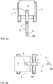
- the upper carriage 3 of the drilling equipment is turned in the manner shown in Figures 2a and 2b about the turning axis 4 to different turning positions, and in each turning position a turning angle ST provided by the angle sensor 7 and inclination values for the upper carriage in the direction of axes SX and SY, provided by the inclination sensors of the inclination measurement device 8, are recorded.
- the upper carriage 3 is preferably turned by an angle of a sufficient size, for example 90°, the inclination sensors of the inclination measurement device 8 thus being at a turning angle of 90°, as shown in Fig. 2b .
- the turning angle may be smaller or greater than 90°, because there is a mathematical correlation between the sensor measurement values, and thus errors caused by the installation of the sensors, i.e. so-called offset values, may be calculated in the following manner.
- Figures 3a and 3b are schematic views of inclinations in the directions of longitudinal and transverse axes x and y of the drilling equipment, formed on the basis of expected error values obtained from a calibration of equipment.
- zero point offset values SXoffset and SYoffset are estimated for both inclination sensors of the inclination measurement device 8, carrier inclinations TY and TX being then computed at each measuring point by means of these zero point offsets.
- TY i f SX i ⁇ SXoffset , SY i ⁇ SYoffset , ST i
- TY i f SX i ⁇ SXoffset , SY i ⁇ SYoffset , TY i , ST i
- SXoffset and SYoffset values of different zero point offsets result in different variations in the carrier inclinations TX[i] and TY[i].
- variation in the carrier inclination values can be minimized. This is illustrated in Fig.3a , which shows changes in inclination values as a function of the turning angle when the SXoffset and SYoffset values of the zero point offsets differ from optimal values.
- Fig. 3b shows graphs that illustrate how correct SXoffset and SYoffset values of zero point offsets always result in substantially correct carrier inclination values, irrespective of the turning angle.
- the SXoffset and SYoffset values of zero point offsets may be calculated by different mathematical methods, for example by using the least squares method to calculate for SXoffset and SYoffset pairs of zero point offset values of turning angles a sum of mean error squares of value series TY[i] and TX[i] corresponding to them. After this, the SXoffset and SYoffset pair of zero point offset values in which the sum of squares of errors is the smallest may be selected. This calculation may be carried out using a calculator 9 which is also used as a positioning device for the equipment orientation.
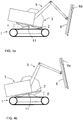
- Figures 4a and 4b in turn show how to calibrate the boom assembly of a turning sensor of the upper carriage and the boom assembly attached thereto or, correspondingly, that of the boom assembly alone.
- the starting point here is that the inclination sensors of the upper carriage have been calibrated in the manner described above.
- the upper carriage 3, and thereby also the boom assembly 5 is kept in the same position in relation to the drilling equipment and it is not turned in relation to the carrier 1 from this position during the calibration.
- the reading of the turn sensor 7 is stored.
- the upper carriage is then tilted in a longitudinal direction of the drilling equipment about the transverse inclination axis 11 in relation to the carrier 1 at suitable inclination intervals between extreme positions ⁇ and ⁇ shown in Figures 4a and 4b .
- the extreme position angles ⁇ and ⁇ may be different or equal in size.
- Inclination values measured by the inclination sensors indicating the inclination of x and y axes of the inclination measurement device 8 are measured for each inclination angle.
- zero point offset may be calculated for the turning angle sensor 7 so that the measurement axes of the sensors of the inclination measurement device 8 are, to the best possible extent, at the 0 angle of the turning sensor in relation to the longitudinal axis of the drilling equipment.
- Fig.5 is a schematic view of another type of drilling equipment. It shows drilling equipment that corresponds to the one in Fig. 1 , except that it does not have an inclination axis between the carrier and the frame, therefore the frame always tilts in the same way as the carrier. Moreover, the drilling equipment of this embodiment does not have a separate upper carriage or cabin for the operator either, although they could be provided, similarly as in the solution of Fig. 1 . Likewise, the drilling equipment of Fig. 1 could be without a cabin and a separate upper carriage.
- inclination measurement device 8 and the related inclination sensors for measuring frame inclination fixedly installed to the frame so that it does not turn with the boom assembly 5 when it is turned.
- calibration is carried out by means of inclination sensors of the feed beam inclination measurement device 12 installed to be immovable in relation to the feed beam 6.
- the boom assembly 5 and the feed beam 6 are first set into a position in which they are able to turn about the turning axis 4 without being prevented by any obstacles possibly present around and they are kept in place so that their position in relation to one another does not change, nor do they turn in relation to the frame 2 of the drilling equipment.
- the feed beam 6 may be installed to an approximately vertical position, for example, although there are no significant requirements of precision regarding the direction as such because deviations in inclination can be taken into account in the computing.
- the boom assembly 5 and the associated feed beams 6 have been installed to a suitable position, the boom assembly is turned about the turning axis 4 to different turning angles and, at the same time, an inclination value provided by the inclination sensors of the feed bean inclination measurement device 12 is measured at each turning angle position.
- inclination values provided by the inclination sensors of the inclination measurement devices 8 of the frame 2 may be measured during calibration, these values remaining the same irrespective of the turning of the boom assembly because the inclination measurement device 8 does not turn with the boom assembly 5.
- the readings provided by the inclination sensors of the inclination measurement device 12 of the feed beam 6 allow offset values of the inclination sensors of the frame inclination measurement device 8 to be determined.
- the method of the invention can naturally be applied not only to suitable calibration of sensors with the help of a computer program but also to continuous condition-monitoring of sensors, the program allowing sensor calibration to be carried out automatically even.
- the figures and the specification disclose only an exemplary equipment in which the method may be used.
- the rolls in the carrier may be replaced by wheels on which the drilling equipment moves.
- the upper carriage may comprise an engine and other actuators with control cabins, if any, and a drilling boom, together with its accessories, attached thereto and turning with it.
- the engine and the other actuators may be attached to the frame, the drilling boom with its accessories being only attached to the upper carriage.
Landscapes
- Engineering & Computer Science (AREA)
- Geology (AREA)
- Life Sciences & Earth Sciences (AREA)
- Mining & Mineral Resources (AREA)
- Physics & Mathematics (AREA)
- Geochemistry & Mineralogy (AREA)
- Fluid Mechanics (AREA)
- General Life Sciences & Earth Sciences (AREA)
- Environmental & Geological Engineering (AREA)
- Manufacturing & Machinery (AREA)
- General Physics & Mathematics (AREA)
- Radar, Positioning & Navigation (AREA)
- Remote Sensing (AREA)
- Geophysics (AREA)
- Earth Drilling (AREA)
- Component Parts Of Construction Machinery (AREA)
Applications Claiming Priority (2)
| Application Number | Priority Date | Filing Date | Title |
|---|---|---|---|
| FI20115739A FI123405B (fi) | 2011-07-08 | 2011-07-08 | Menetelmä porauslaitteen anturien kalibroimiseksi |
| PCT/FI2012/050711 WO2013007879A1 (en) | 2011-07-08 | 2012-07-06 | Method and arrangement for calibrating sensors in drilling equipment |
Publications (3)
| Publication Number | Publication Date |
|---|---|
| EP2729652A1 EP2729652A1 (en) | 2014-05-14 |
| EP2729652A4 EP2729652A4 (en) | 2016-01-06 |
| EP2729652B1 true EP2729652B1 (en) | 2019-04-10 |
Family
ID=44318407
Family Applications (1)
| Application Number | Title | Priority Date | Filing Date |
|---|---|---|---|
| EP12811783.5A Active EP2729652B1 (en) | 2011-07-08 | 2012-07-06 | Method and arrangement for calibrating sensors in drilling equipment |
Country Status (7)
| Country | Link |
|---|---|
| US (1) | US9739136B2 (zh) |
| EP (1) | EP2729652B1 (zh) |
| JP (1) | JP5809357B2 (zh) |
| CN (1) | CN103649450B (zh) |
| AU (1) | AU2012282360B2 (zh) |
| FI (1) | FI123405B (zh) |
| WO (1) | WO2013007879A1 (zh) |
Families Citing this family (14)
| Publication number | Priority date | Publication date | Assignee | Title |
|---|---|---|---|---|
| WO2012117992A1 (ja) | 2011-03-02 | 2012-09-07 | 株式会社村田製作所 | 高周波モジュール |
| US20140166362A1 (en) * | 2012-12-14 | 2014-06-19 | Caterpillar Inc. | Implement Pose Control System and Method |
| JP6689660B2 (ja) * | 2016-04-21 | 2020-04-28 | 株式会社加藤製作所 | 建設機械の傾斜検出装置 |
| US11091962B2 (en) | 2016-07-01 | 2021-08-17 | Sandvik Mining And Construction Oy | Apparatus and method for positioning rock drilling rig |
| JP6836118B2 (ja) * | 2016-07-29 | 2021-02-24 | 株式会社タダノ | 加速度センサの調整システム |
| IT201700022610A1 (it) * | 2017-02-28 | 2018-08-28 | Gd Spa | Metodo e kit per la regolazione di una macchina di confezionamento o di impacchettamento di articoli. |
| CN107829721B (zh) * | 2017-09-21 | 2018-10-30 | 中国科学院地质与地球物理研究所 | 一种适用于钻具姿态测量模块的动态测试装置 |
| NO20180946A1 (en) * | 2018-07-05 | 2020-01-06 | Mhwirth As | Position Measuring Method and System for use on a Floating Installation |
| US11002075B1 (en) | 2018-07-31 | 2021-05-11 | J.H. Fletcher & Co. | Mine drilling system and related method |
| DK180402B1 (en) * | 2019-08-13 | 2021-04-06 | Unicontrol Aps | Position Detection Unit and Method for Detecting the Position of an Excavator for an Excavator |
| CN111501895A (zh) * | 2020-03-23 | 2020-08-07 | 潍柴动力股份有限公司 | 挖掘机传感器的标定方法、标定装置和标定系统 |
| US11965408B2 (en) * | 2020-10-30 | 2024-04-23 | Vector Magnetics, Llc | Magnetic borehole surveying method and apparatus |
| CN112554787B (zh) * | 2020-12-03 | 2024-02-02 | 重庆文理学院 | 一种用于隧道打孔的tbm机械改进自走式打孔装置及其使用方法 |
| CN115217416B (zh) * | 2022-08-02 | 2023-09-05 | 山东省地质矿产勘查开发局第六地质大队(山东省第六地质矿产勘查院) | 一种地质用xy型钻机方位角度校正设备 |
Family Cites Families (15)
| Publication number | Priority date | Publication date | Assignee | Title |
|---|---|---|---|---|
| US4274494A (en) | 1977-05-16 | 1981-06-23 | Atlas Copco Aktiebolag | Method and device for setting the direction and/or the inclination of an elongated rock drilling apparatus |
| NO150451C (no) | 1981-04-29 | 1984-10-24 | Furuholmen As Ing Thor | Fremgangsmaate for oppretting av fjellbor |
| FI88426C (fi) * | 1990-10-08 | 1993-05-10 | Tampella Oy Ab | Foerfarande och anordning foer riktande av borrmaskins matarbalk |
| FI88427C (fi) | 1990-11-30 | 1993-05-10 | Tampella Oy Ab | Foerfarande foer riktande av bergborranordningens matarbalk samt bergborranordning och maetningsanordning |
| FI107182B (fi) * | 1998-12-09 | 2001-06-15 | Tamrock Oy | Menetelmä asemointivirheiden korjaamiseksi kallionporauksessa ja kallionporauslaitteisto |
| JP2001159518A (ja) | 1999-11-30 | 2001-06-12 | Komatsu Ltd | 建設機械のツール位置計測装置、ヨー角検出装置、作業機自動制御装置及び校正装置 |
| JP2008002842A (ja) * | 2006-06-20 | 2008-01-10 | Sumitomo Heavy Ind Ltd | 作業機械の姿勢計測方法及び姿勢計測装置 |
| JP4978100B2 (ja) | 2006-08-04 | 2012-07-18 | 株式会社日立製作所 | 測位装置及び初期化方法 |
| SE530874C2 (sv) * | 2007-02-14 | 2008-09-30 | Atlas Copco Rock Drills Ab | Anordning och metod för positionsbestämning av en gruv- eller anläggningsmaskin |
| US7930148B1 (en) * | 2007-08-20 | 2011-04-19 | PNI Sensor Corporation | Spherical calibration and reference alignment algorithms |
| US8122974B2 (en) * | 2008-07-10 | 2012-02-28 | Dragan Kosoric | Apparatus for drilling machine alignment |
| FI122797B (fi) * | 2008-09-08 | 2012-07-13 | Sandvik Mining & Constr Oy | Kallionporauslaite, menetelmä kaivosajoneuvon puomin liikuttamiseksi sekä kaivosajoneuvo |
| CN101798916B (zh) * | 2010-02-26 | 2012-07-04 | 北京市三一重机有限公司 | 一种入岩钻机及其控制系统和控制方法 |
| CN102108854A (zh) * | 2010-12-24 | 2011-06-29 | 北京市三一重机有限公司 | 旋挖钻机自动防倾翻控制系统及其控制方法 |
| JP5237408B2 (ja) * | 2011-03-24 | 2013-07-17 | 株式会社小松製作所 | 油圧ショベルの較正システム及び較正方法 |
-
2011
- 2011-07-08 FI FI20115739A patent/FI123405B/fi not_active IP Right Cessation
-
2012
- 2012-07-06 EP EP12811783.5A patent/EP2729652B1/en active Active
- 2012-07-06 US US14/131,253 patent/US9739136B2/en active Active
- 2012-07-06 JP JP2014519594A patent/JP5809357B2/ja not_active Expired - Fee Related
- 2012-07-06 CN CN201280034012.5A patent/CN103649450B/zh not_active Expired - Fee Related
- 2012-07-06 AU AU2012282360A patent/AU2012282360B2/en not_active Ceased
- 2012-07-06 WO PCT/FI2012/050711 patent/WO2013007879A1/en active Application Filing
Non-Patent Citations (1)
| Title |
|---|
| None * |
Also Published As
| Publication number | Publication date |
|---|---|
| AU2012282360B2 (en) | 2015-12-03 |
| JP5809357B2 (ja) | 2015-11-10 |
| EP2729652A4 (en) | 2016-01-06 |
| US20140157860A1 (en) | 2014-06-12 |
| WO2013007879A1 (en) | 2013-01-17 |
| EP2729652A1 (en) | 2014-05-14 |
| US9739136B2 (en) | 2017-08-22 |
| FI123405B (fi) | 2013-03-28 |
| CN103649450B (zh) | 2015-11-25 |
| CN103649450A (zh) | 2014-03-19 |
| JP2014524030A (ja) | 2014-09-18 |
| FI20115739A (fi) | 2013-01-09 |
| AU2012282360A1 (en) | 2014-01-23 |
| FI20115739A0 (fi) | 2011-07-08 |
Similar Documents
| Publication | Publication Date | Title |
|---|---|---|
| EP2729652B1 (en) | Method and arrangement for calibrating sensors in drilling equipment | |
| US9540794B2 (en) | Calibration device for work machine and calibration method of working equipment parameter for work machine | |
| KR101669787B1 (ko) | 유압 쇼벨의 교정 시스템 및 교정 방법 | |
| US8634991B2 (en) | Grade control for an earthmoving system at higher machine speeds | |
| KR101516693B1 (ko) | 유압 셔블의 굴삭 제어 시스템 | |
| US9481984B2 (en) | Calibration device for work machine and calibration method of working equipment parameter for work machine | |
| US9746329B2 (en) | Systems and methods for augmenting an inertial navigation system | |
| US7650252B2 (en) | Inclinometer measurement system and method providing correction for movement induced acceleration errors | |
| US5383524A (en) | Method and equipment for aligning the feeding beam of a rock drilling equipment | |
| US20170260717A1 (en) | Work machine and correction method of working equipment parameter for work machine | |
| KR20190112058A (ko) | 건설 기계 | |
| EP2208019B1 (de) | Verfahren und vorrichtung zur bestimmung eines objektes aus hybriden messungen | |
| US12031303B2 (en) | Work machine | |
| JP6918524B2 (ja) | 建築作業機械における傾斜センサー補正量取得方法 | |
| JP6878051B2 (ja) | 排土板の位置補正量取得方法 | |
| JP6905137B2 (ja) | 建築作業機械における傾斜センサー補正量取得方法 | |
| RU2478757C2 (ru) | Способ определения положения режущей кромки отвала автогрейдера | |
| CN111851634B (zh) | 测量第一轴的中心轴线相对于第二轴的中心轴线的三维位置和方向的测量布置 | |
| RETSCHER | Trajectory determination for machine guidance systems | |
| KUSTER | Method and device for determining machine position from hybrid measurements |
Legal Events
| Date | Code | Title | Description |
|---|---|---|---|
| PUAI | Public reference made under article 153(3) epc to a published international application that has entered the european phase |
Free format text: ORIGINAL CODE: 0009012 |
|
| 17P | Request for examination filed |
Effective date: 20140210 |
|
| AK | Designated contracting states |
Kind code of ref document: A1 Designated state(s): AL AT BE BG CH CY CZ DE DK EE ES FI FR GB GR HR HU IE IS IT LI LT LU LV MC MK MT NL NO PL PT RO RS SE SI SK SM TR |
|
| DAX | Request for extension of the european patent (deleted) | ||
| RA4 | Supplementary search report drawn up and despatched (corrected) |
Effective date: 20151204 |
|
| RIC1 | Information provided on ipc code assigned before grant |
Ipc: E21B 7/02 20060101AFI20151130BHEP Ipc: E21B 44/00 20060101ALI20151130BHEP |
|
| STAA | Information on the status of an ep patent application or granted ep patent |
Free format text: STATUS: EXAMINATION IS IN PROGRESS |
|
| 17Q | First examination report despatched |
Effective date: 20170704 |
|
| GRAP | Despatch of communication of intention to grant a patent |
Free format text: ORIGINAL CODE: EPIDOSNIGR1 |
|
| STAA | Information on the status of an ep patent application or granted ep patent |
Free format text: STATUS: GRANT OF PATENT IS INTENDED |
|
| INTG | Intention to grant announced |
Effective date: 20181114 |
|
| GRAS | Grant fee paid |
Free format text: ORIGINAL CODE: EPIDOSNIGR3 |
|
| GRAA | (expected) grant |
Free format text: ORIGINAL CODE: 0009210 |
|
| STAA | Information on the status of an ep patent application or granted ep patent |
Free format text: STATUS: THE PATENT HAS BEEN GRANTED |
|
| AK | Designated contracting states |
Kind code of ref document: B1 Designated state(s): AL AT BE BG CH CY CZ DE DK EE ES FI FR GB GR HR HU IE IS IT LI LT LU LV MC MK MT NL NO PL PT RO RS SE SI SK SM TR |
|
| REG | Reference to a national code |
Ref country code: GB Ref legal event code: FG4D |
|
| REG | Reference to a national code |
Ref country code: CH Ref legal event code: EP Ref country code: AT Ref legal event code: REF Ref document number: 1118870 Country of ref document: AT Kind code of ref document: T Effective date: 20190415 |
|
| REG | Reference to a national code |
Ref country code: DE Ref legal event code: R096 Ref document number: 602012058907 Country of ref document: DE |
|
| REG | Reference to a national code |
Ref country code: IE Ref legal event code: FG4D |
|
| REG | Reference to a national code |
Ref country code: SE Ref legal event code: TRGR |
|
| REG | Reference to a national code |
Ref country code: NO Ref legal event code: T2 Effective date: 20190410 |
|
| REG | Reference to a national code |
Ref country code: NL Ref legal event code: MP Effective date: 20190410 |
|
| REG | Reference to a national code |
Ref country code: LT Ref legal event code: MG4D |
|
| REG | Reference to a national code |
Ref country code: AT Ref legal event code: MK05 Ref document number: 1118870 Country of ref document: AT Kind code of ref document: T Effective date: 20190410 |
|
| PG25 | Lapsed in a contracting state [announced via postgrant information from national office to epo] |
Ref country code: NL Free format text: LAPSE BECAUSE OF FAILURE TO SUBMIT A TRANSLATION OF THE DESCRIPTION OR TO PAY THE FEE WITHIN THE PRESCRIBED TIME-LIMIT Effective date: 20190410 |
|
| PG25 | Lapsed in a contracting state [announced via postgrant information from national office to epo] |
Ref country code: AL Free format text: LAPSE BECAUSE OF FAILURE TO SUBMIT A TRANSLATION OF THE DESCRIPTION OR TO PAY THE FEE WITHIN THE PRESCRIBED TIME-LIMIT Effective date: 20190410 Ref country code: PT Free format text: LAPSE BECAUSE OF FAILURE TO SUBMIT A TRANSLATION OF THE DESCRIPTION OR TO PAY THE FEE WITHIN THE PRESCRIBED TIME-LIMIT Effective date: 20190910 Ref country code: HR Free format text: LAPSE BECAUSE OF FAILURE TO SUBMIT A TRANSLATION OF THE DESCRIPTION OR TO PAY THE FEE WITHIN THE PRESCRIBED TIME-LIMIT Effective date: 20190410 Ref country code: LT Free format text: LAPSE BECAUSE OF FAILURE TO SUBMIT A TRANSLATION OF THE DESCRIPTION OR TO PAY THE FEE WITHIN THE PRESCRIBED TIME-LIMIT Effective date: 20190410 Ref country code: ES Free format text: LAPSE BECAUSE OF FAILURE TO SUBMIT A TRANSLATION OF THE DESCRIPTION OR TO PAY THE FEE WITHIN THE PRESCRIBED TIME-LIMIT Effective date: 20190410 |
|
| PG25 | Lapsed in a contracting state [announced via postgrant information from national office to epo] |
Ref country code: PL Free format text: LAPSE BECAUSE OF FAILURE TO SUBMIT A TRANSLATION OF THE DESCRIPTION OR TO PAY THE FEE WITHIN THE PRESCRIBED TIME-LIMIT Effective date: 20190410 Ref country code: RS Free format text: LAPSE BECAUSE OF FAILURE TO SUBMIT A TRANSLATION OF THE DESCRIPTION OR TO PAY THE FEE WITHIN THE PRESCRIBED TIME-LIMIT Effective date: 20190410 Ref country code: BG Free format text: LAPSE BECAUSE OF FAILURE TO SUBMIT A TRANSLATION OF THE DESCRIPTION OR TO PAY THE FEE WITHIN THE PRESCRIBED TIME-LIMIT Effective date: 20190710 Ref country code: GR Free format text: LAPSE BECAUSE OF FAILURE TO SUBMIT A TRANSLATION OF THE DESCRIPTION OR TO PAY THE FEE WITHIN THE PRESCRIBED TIME-LIMIT Effective date: 20190711 Ref country code: LV Free format text: LAPSE BECAUSE OF FAILURE TO SUBMIT A TRANSLATION OF THE DESCRIPTION OR TO PAY THE FEE WITHIN THE PRESCRIBED TIME-LIMIT Effective date: 20190410 |
|
| PG25 | Lapsed in a contracting state [announced via postgrant information from national office to epo] |
Ref country code: IS Free format text: LAPSE BECAUSE OF FAILURE TO SUBMIT A TRANSLATION OF THE DESCRIPTION OR TO PAY THE FEE WITHIN THE PRESCRIBED TIME-LIMIT Effective date: 20190810 Ref country code: AT Free format text: LAPSE BECAUSE OF FAILURE TO SUBMIT A TRANSLATION OF THE DESCRIPTION OR TO PAY THE FEE WITHIN THE PRESCRIBED TIME-LIMIT Effective date: 20190410 |
|
| REG | Reference to a national code |
Ref country code: DE Ref legal event code: R097 Ref document number: 602012058907 Country of ref document: DE |
|
| PG25 | Lapsed in a contracting state [announced via postgrant information from national office to epo] |
Ref country code: DK Free format text: LAPSE BECAUSE OF FAILURE TO SUBMIT A TRANSLATION OF THE DESCRIPTION OR TO PAY THE FEE WITHIN THE PRESCRIBED TIME-LIMIT Effective date: 20190410 Ref country code: EE Free format text: LAPSE BECAUSE OF FAILURE TO SUBMIT A TRANSLATION OF THE DESCRIPTION OR TO PAY THE FEE WITHIN THE PRESCRIBED TIME-LIMIT Effective date: 20190410 Ref country code: RO Free format text: LAPSE BECAUSE OF FAILURE TO SUBMIT A TRANSLATION OF THE DESCRIPTION OR TO PAY THE FEE WITHIN THE PRESCRIBED TIME-LIMIT Effective date: 20190410 Ref country code: SK Free format text: LAPSE BECAUSE OF FAILURE TO SUBMIT A TRANSLATION OF THE DESCRIPTION OR TO PAY THE FEE WITHIN THE PRESCRIBED TIME-LIMIT Effective date: 20190410 Ref country code: CZ Free format text: LAPSE BECAUSE OF FAILURE TO SUBMIT A TRANSLATION OF THE DESCRIPTION OR TO PAY THE FEE WITHIN THE PRESCRIBED TIME-LIMIT Effective date: 20190410 |
|
| PLBE | No opposition filed within time limit |
Free format text: ORIGINAL CODE: 0009261 |
|
| STAA | Information on the status of an ep patent application or granted ep patent |
Free format text: STATUS: NO OPPOSITION FILED WITHIN TIME LIMIT |
|
| PG25 | Lapsed in a contracting state [announced via postgrant information from national office to epo] |
Ref country code: MC Free format text: LAPSE BECAUSE OF FAILURE TO SUBMIT A TRANSLATION OF THE DESCRIPTION OR TO PAY THE FEE WITHIN THE PRESCRIBED TIME-LIMIT Effective date: 20190410 Ref country code: SM Free format text: LAPSE BECAUSE OF FAILURE TO SUBMIT A TRANSLATION OF THE DESCRIPTION OR TO PAY THE FEE WITHIN THE PRESCRIBED TIME-LIMIT Effective date: 20190410 Ref country code: IT Free format text: LAPSE BECAUSE OF FAILURE TO SUBMIT A TRANSLATION OF THE DESCRIPTION OR TO PAY THE FEE WITHIN THE PRESCRIBED TIME-LIMIT Effective date: 20190410 |
|
| REG | Reference to a national code |
Ref country code: CH Ref legal event code: PL |
|
| 26N | No opposition filed |
Effective date: 20200113 |
|
| GBPC | Gb: european patent ceased through non-payment of renewal fee |
Effective date: 20190710 |
|
| PG25 | Lapsed in a contracting state [announced via postgrant information from national office to epo] |
Ref country code: TR Free format text: LAPSE BECAUSE OF FAILURE TO SUBMIT A TRANSLATION OF THE DESCRIPTION OR TO PAY THE FEE WITHIN THE PRESCRIBED TIME-LIMIT Effective date: 20190410 |
|
| REG | Reference to a national code |
Ref country code: BE Ref legal event code: MM Effective date: 20190731 |
|
| PG25 | Lapsed in a contracting state [announced via postgrant information from national office to epo] |
Ref country code: GB Free format text: LAPSE BECAUSE OF NON-PAYMENT OF DUE FEES Effective date: 20190710 |
|
| PG25 | Lapsed in a contracting state [announced via postgrant information from national office to epo] |
Ref country code: LU Free format text: LAPSE BECAUSE OF NON-PAYMENT OF DUE FEES Effective date: 20190706 Ref country code: LI Free format text: LAPSE BECAUSE OF NON-PAYMENT OF DUE FEES Effective date: 20190731 Ref country code: SI Free format text: LAPSE BECAUSE OF FAILURE TO SUBMIT A TRANSLATION OF THE DESCRIPTION OR TO PAY THE FEE WITHIN THE PRESCRIBED TIME-LIMIT Effective date: 20190410 Ref country code: CH Free format text: LAPSE BECAUSE OF NON-PAYMENT OF DUE FEES Effective date: 20190731 Ref country code: BE Free format text: LAPSE BECAUSE OF NON-PAYMENT OF DUE FEES Effective date: 20190731 |
|
| PG25 | Lapsed in a contracting state [announced via postgrant information from national office to epo] |
Ref country code: IE Free format text: LAPSE BECAUSE OF NON-PAYMENT OF DUE FEES Effective date: 20190706 |
|
| PG25 | Lapsed in a contracting state [announced via postgrant information from national office to epo] |
Ref country code: CY Free format text: LAPSE BECAUSE OF FAILURE TO SUBMIT A TRANSLATION OF THE DESCRIPTION OR TO PAY THE FEE WITHIN THE PRESCRIBED TIME-LIMIT Effective date: 20190410 |
|
| PG25 | Lapsed in a contracting state [announced via postgrant information from national office to epo] |
Ref country code: MT Free format text: LAPSE BECAUSE OF FAILURE TO SUBMIT A TRANSLATION OF THE DESCRIPTION OR TO PAY THE FEE WITHIN THE PRESCRIBED TIME-LIMIT Effective date: 20190410 Ref country code: HU Free format text: LAPSE BECAUSE OF FAILURE TO SUBMIT A TRANSLATION OF THE DESCRIPTION OR TO PAY THE FEE WITHIN THE PRESCRIBED TIME-LIMIT; INVALID AB INITIO Effective date: 20120706 |
|
| PG25 | Lapsed in a contracting state [announced via postgrant information from national office to epo] |
Ref country code: MK Free format text: LAPSE BECAUSE OF FAILURE TO SUBMIT A TRANSLATION OF THE DESCRIPTION OR TO PAY THE FEE WITHIN THE PRESCRIBED TIME-LIMIT Effective date: 20190410 |
|
| PGFP | Annual fee paid to national office [announced via postgrant information from national office to epo] |
Ref country code: FR Payment date: 20230622 Year of fee payment: 12 |
|
| PGFP | Annual fee paid to national office [announced via postgrant information from national office to epo] |
Ref country code: NO Payment date: 20230712 Year of fee payment: 12 Ref country code: FI Payment date: 20230712 Year of fee payment: 12 |
|
| PGFP | Annual fee paid to national office [announced via postgrant information from national office to epo] |
Ref country code: DE Payment date: 20230607 Year of fee payment: 12 |
|
| PGFP | Annual fee paid to national office [announced via postgrant information from national office to epo] |
Ref country code: SE Payment date: 20240529 Year of fee payment: 13 |