EP2729397B2 - Procédé et dispositif permettant de déplacer une bande de matériau - Google Patents
Procédé et dispositif permettant de déplacer une bande de matériau Download PDFInfo
- Publication number
- EP2729397B2 EP2729397B2 EP12769953.6A EP12769953A EP2729397B2 EP 2729397 B2 EP2729397 B2 EP 2729397B2 EP 12769953 A EP12769953 A EP 12769953A EP 2729397 B2 EP2729397 B2 EP 2729397B2
- Authority
- EP
- European Patent Office
- Prior art keywords
- drive unit
- torque
- power
- acceleration
- conveyor means
- Prior art date
- Legal status (The legal status is an assumption and is not a legal conclusion. Google has not performed a legal analysis and makes no representation as to the accuracy of the status listed.)
- Active
Links
Images
Classifications
-
- B—PERFORMING OPERATIONS; TRANSPORTING
- B65—CONVEYING; PACKING; STORING; HANDLING THIN OR FILAMENTARY MATERIAL
- B65H—HANDLING THIN OR FILAMENTARY MATERIAL, e.g. SHEETS, WEBS, CABLES
- B65H23/00—Registering, tensioning, smoothing or guiding webs
- B65H23/04—Registering, tensioning, smoothing or guiding webs longitudinally
- B65H23/18—Registering, tensioning, smoothing or guiding webs longitudinally by controlling or regulating the web-advancing mechanism, e.g. mechanism acting on the running web
- B65H23/182—Registering, tensioning, smoothing or guiding webs longitudinally by controlling or regulating the web-advancing mechanism, e.g. mechanism acting on the running web in unwinding mechanisms or in connection with unwinding operations
- B65H23/185—Registering, tensioning, smoothing or guiding webs longitudinally by controlling or regulating the web-advancing mechanism, e.g. mechanism acting on the running web in unwinding mechanisms or in connection with unwinding operations motor-controlled
-
- B—PERFORMING OPERATIONS; TRANSPORTING
- B65—CONVEYING; PACKING; STORING; HANDLING THIN OR FILAMENTARY MATERIAL
- B65H—HANDLING THIN OR FILAMENTARY MATERIAL, e.g. SHEETS, WEBS, CABLES
- B65H23/00—Registering, tensioning, smoothing or guiding webs
- B65H23/04—Registering, tensioning, smoothing or guiding webs longitudinally
- B65H23/18—Registering, tensioning, smoothing or guiding webs longitudinally by controlling or regulating the web-advancing mechanism, e.g. mechanism acting on the running web
- B65H23/195—Registering, tensioning, smoothing or guiding webs longitudinally by controlling or regulating the web-advancing mechanism, e.g. mechanism acting on the running web in winding mechanisms or in connection with winding operations
- B65H23/198—Registering, tensioning, smoothing or guiding webs longitudinally by controlling or regulating the web-advancing mechanism, e.g. mechanism acting on the running web in winding mechanisms or in connection with winding operations motor-controlled (Controlling electrical drive motors therefor)
-
- B—PERFORMING OPERATIONS; TRANSPORTING
- B65—CONVEYING; PACKING; STORING; HANDLING THIN OR FILAMENTARY MATERIAL
- B65H—HANDLING THIN OR FILAMENTARY MATERIAL, e.g. SHEETS, WEBS, CABLES
- B65H2220/00—Function indicators
- B65H2220/02—Function indicators indicating an entity which is controlled, adjusted or changed by a control process, i.e. output
-
- B—PERFORMING OPERATIONS; TRANSPORTING
- B65—CONVEYING; PACKING; STORING; HANDLING THIN OR FILAMENTARY MATERIAL
- B65H—HANDLING THIN OR FILAMENTARY MATERIAL, e.g. SHEETS, WEBS, CABLES
- B65H2513/00—Dynamic entities; Timing aspects
- B65H2513/20—Acceleration or deceleration
-
- B—PERFORMING OPERATIONS; TRANSPORTING
- B65—CONVEYING; PACKING; STORING; HANDLING THIN OR FILAMENTARY MATERIAL
- B65H—HANDLING THIN OR FILAMENTARY MATERIAL, e.g. SHEETS, WEBS, CABLES
- B65H2515/00—Physical entities not provided for in groups B65H2511/00 or B65H2513/00
- B65H2515/70—Electrical or magnetic properties, e.g. electric power or current
Definitions
- the invention relates to a method for moving a web of material with conveying means that can be driven by at least one drive unit.
- the invention relates to a controller and a machine with at least one drive unit and with conveying means that can be driven by the at least one drive unit.
- the invention further relates to a computer program and a computer program product.
- Such a method and such devices are used in particular where machines move continuous webs of material by means of electrically driven rollers and cylinders.
- these cylinders and rollers have large masses of inertia that depend on the amount of material wound up, so that the time required for acceleration and braking can be in the range of several minutes.
- This ramp time mainly depends on the factors of friction and mass inertia.
- the mass inertia is strongly dependent on the amount of material wound up.
- a programmable controller is known by means of which a calibration between successive winding and unwinding processes of a tape as well as an automatic generation of a current reference value for a control of a motor of a winding or unwinding roller is made possible in real time.
- the controller includes a computing unit for determining the roller diameter and compensation for a deviation in the belt speed and inertia compensation.
- EP 1 958 905 A2 further describes a method and a device for compensating for friction in a winding machine. Furthermore, in EP 1 958 905 A2 discloses a control method for friction compensation in a winding machine.
- the object of the invention is to reduce the times for accelerating and decelerating a web of material using existing drives or to be able to use drives with lower power and torque limits for the same time requirements.
- this object is achieved by a method for moving a web of material with conveying means that can be driven by at least one drive unit according to the features of claim 1 .
- the method can be used in particular in paper, foil or steel processing machines in which continuous webs of material are moved by means of electrically drivable conveying means.
- These conveyors can be designed, for example, as rollers, cylinders, conveyor belts or the like and, together with the webs of material moved with them, can have a high mass inertia.
- the advantage of the method according to the present invention is the possibility of being able to quickly change the movement of a web. In particular when accelerating a material web, the process allows a movement that is optimal in terms of torque and performance. This is also possible when the mass inertia of the conveyor or the web changes, for example by winding the web onto the conveyor.
- the concept of acceleration is understood as a positive or negative change in speed, so that the speed can increase or decrease in absolute terms during an acceleration.
- the distinction is based on the fact that, particularly in the case of electric drives, the torque is the limiting variable for acceleration at low speeds or speeds.
- a drive unit can provide a comparatively high torque at a low speed or speed, whereas the power of the drive unit is comparatively low and increases proportionally to the speed or speed.
- the power of the drive unit is the limiting factor for acceleration.
- the drive unit can provide comparatively high power, with the torque reducing for increasing speeds or speeds.
- a torque and a power can now be specified, otherwise stored values can be used.
- the at least one drive unit requires a certain torque and a certain power to accelerate the conveying means and the material web.
- the method now provides for accelerating the conveying means with the definable torque if the power required for this is less than the definable power. If the amount of torque required for acceleration is smaller than the torque that can be specified, the conveying means are accelerated with the power that can be specified. In the case of real drives, brief overshoots can occur during which a greater torque than the specifiable torque or a higher power than the specifiable power is made available.
- the acceleration is accomplished by the drive unit, to which appropriate current setpoint values are specified.
- the specification of the desired current values can be preceded by further steps, such as specifying desired ramp times.
- the method also provides for ending the acceleration process as soon as a desired movement or speed of the material web has been reached. In particular, this can be the run-up of the material line up to a certain speed or the complete standstill of the material line.
- the predefinable power can be, for example, a specific percentage of the rated power of the at least one drive unit and the predefinable torque can be, for example, a specific percentage of the rated torque of the at least one drive unit.
- the predefinable torque of the at least one drive unit is the rated torque of the at least one drive unit and the predefinable power is the rated power of the at least one drive unit.
- the use of the nominal torque or the nominal power of the at least one drive unit allows the fastest possible acceleration of the funding.
- the funding - e.g. B. starting from standstill - accelerated using the rated torque until that speed or speed is reached for which the drive unit requires the rated power. From this speed, the conveyor can continue to be accelerated using the rated power, with the torque being reduced as the speed or speed increases. Finally, the acceleration process is terminated as soon as the desired movement of the material has been achieved.
- this acceleration of the web is achieved using the nominal power of the at least one drive unit, provided that the torque required for this is smaller than the nominal torque.
- the material web is decelerated by the at least one drive unit using the nominal power until the amount of torque required for this is equal to the nominal torque of the at least one drive unit.
- the material web is then further braked with the rated torque of the drive unit, the braking power now being less than the rated power of the at least one drive unit.
- the at least one drive unit can be designed, for example, in such a way that at least one rectifier, which rectifies an AC voltage of the supply network into an intermediate circuit voltage, at least one intermediate circuit capacitor and at least one inverter, which inverts the intermediate circuit voltage into an AC voltage of variable frequency, are provided. If a rectifier and multiple inverters are used, the inverters can have a greater total power than the rectifier, so that the power of the at least one drive unit is limited by the rectifier. In this case, the rated power of the at least one drive unit is given by the rated power of the rectifier.
- the method can be checked and fed back in such a way that the current setpoint values for the drive unit are corrected and adjusted if necessary.
- the actual values of the torque and the power of the at least one drive unit can be determined in particular by a converter that is comprised by the at least one drive unit.
- the acceleration of the conveying means is performed as a deceleration of the movement of the material web and the at least one drive unit is operated as a generator.
- the generator operation of a drive unit of the machine is particularly interesting with regard to environmental protection, energy savings and cost reduction. This is because when the conveyor is braked, its kinetic energy can be fed back into the power grid by the at least one drive unit in the form of electrical energy. Overall, the machine thus consumes less energy, which is synonymous with cost reduction and improved environmental protection.
- the acceleration of the conveying means is performed as a deceleration of the movement of the web of material, and the movement of the web of material is additionally decelerated by means of a brake.
- Greater acceleration of the conveyor can be achieved through the use of a brake, resulting in increased productivity of the machine since the time to decelerate the machine to a desired movement can be reduced. Consequently, the cost can be further reduced.
- the conveying means comprise a winding cylinder, which can also be designed as a roller or some other device for winding up a web of material.
- the web of material is wound up or unwound onto the winding cylinder, and since the web of material itself has a specific thickness, the material wound up on the cylinder has a specific winding thickness of the material, which is detected.
- the torque required for accelerating the conveying means, the torque required for accelerating the conveying means and/or the desired current values are recorded and stored for a detected winding thickness. This can take place, for example, in a controller in which the dependency of the variables mentioned on the recorded material winding thickness of the material web wound onto the winding cylinder is present.
- the stored information can be used when detecting a specific roll thickness currently present on the cylinder.
- a learning process thus takes place, and a machine on which the method is applied is characterized by a certain "intelligence". This is particularly advantageous if different types of webs are used which have different properties, thicknesses or masses and the dependency mentioned is stored separately for each of the different webs of material.
- the stated ratio of the required torque in relation to the maximum torque that can be achieved by a drive unit or the corresponding ratio in relation to the power outputs expresses whether the drive unit under consideration is able to bring about the desired acceleration. If this is not the case and the desired acceleration cannot be achieved, the determined ratio is greater than 1.
- the ratio for each of the drive units determined. If one of the determined ratios is greater than 1, the maximum acceleration that can be achieved is determined for the drive unit that has the largest determined ratio and is therefore most overwhelmed. Finally, the funds are accelerated with the determined maximum acceleration that can be achieved. So that means that the drive unit with the largest determined ratio and which is most overwhelmed specifies the acceleration of the conveyor.
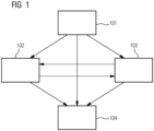
- figure 1 shows a flow chart of the method according to the present invention for moving a web 1.
- step 101 a desired movement of the web 1 is compared with the current movement of the web 1 . If the current movement of the web of material 1 is equal to the desired movement of the web of material 1, step 104 is carried out, in which the method is ended. However, if the current movement and the desired movement of the web of material 1 are different, the web of material 1 is accelerated by means of conveying means 3 , 13 that can be driven by at least one drive unit 2 . To this end, a distinction is made between two cases, for which corresponding desired current values 11 are specified for the at least one drive unit 2 in each case.
- step 102 the conveying means 3, 13 are accelerated by the at least one drive unit 2 with a specifiable torque 4 if the power required for this is less than a specifiable power 5 of the at least one drive unit 2.
- step 103 the conveying means 3, 13 are accelerated by the at least one drive unit 2 with the specifiable power 5 if the amount of torque required for this is smaller than the specifiable torque 4 of the at least one drive unit 2. If step 102 or 103 has been carried out, step 103 or 102 can then be carried out or the acceleration process is ended in accordance with 104 as soon as a desired movement of the material web 1 has been achieved.
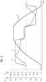
- figure 2 shows an exemplary time course of the speed 8 of a web 1, an actual torque value 6 and an actual power value 7 according to the method of the present invention.
- the time is plotted on the abscissa and the speed 8 of a material web 1 is plotted on the ordinate axis with a scale from 0 to 2000.
- the ordinate axis also shows an actual torque value 6 and a Actual power value 7 plotted.
- the two latter variables are expressed as a relative variable in % in relation to the corresponding nominal values of a drive unit 2 , with the drive unit 2 being able to accelerate conveying means 3 , 13 which move the material web 1 . for in figure 2
- the nominal power of the drive unit 2 is reached, so that with a further increasing speed 8 the actual power value 7 corresponds to the nominal power of the drive unit 2 and the actual torque value 6 is reduced with increasing speed 8 .
- the acceleration of the web 1 and the conveyors 3, 13 is finally terminated as soon as the desired movement, ie a desired speed 8 has been reached. In order to maintain a certain speed 8, then only that power and that torque are required, which the occurring compensate for friction losses.
- the drive unit 2 In order to decelerate a moving web 1, ie to accelerate it in the opposite direction to the direction of movement, the drive unit 2 first uses the rated power of the drive unit as the actual power value 7, with an actual torque value 6 being used, the absolute value of which is smaller than the torque Rated value of the drive unit 2.
- the actual power value 7 is kept constant as the speed 8 decreases, with the actual torque value increasing until the rated torque value of the drive unit 2 is reached.
- the actual torque value 6 is now kept constant equal to the nominal torque of the drive unit 2 and the actual power value 7 is reduced as the speed 8 decreases.
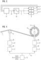
- figure 3 shows a block diagram of a first embodiment of the method according to the present invention.
- nominal current values 11 are specified by a ramp-function generator 24 .
- the setpoints can either be transferred directly to all drive units 2 or via a setpoint scale or via a setpoint cascade.
- the ramp-function generator 24 can also be designed as a ramp generator or the like.
- the drives 2 can carry out a movement using a respective actual torque value 6 and a respective actual power value 7 which are registered by a ramp adaptation 21 .
- a value for the acceleration rate 22 is thus determined, which is transmitted to the ramp-function generator 24 . This in turn generates the desired current values 11 which are specified for the drive units 2 .
- FIG 4 shows a block diagram of a first embodiment of the machine according to the present invention.
- a web of material 1 is moved over a roller 3 to a winding cylinder 13 on which the web of material 1 is wound.
- the material web 1 wound on the winding cylinder 13 has a material winding thickness 14 .
- the roller 3 and the winding cylinder 13 are each driven via a drive shaft 20 which is each provided with a brake 12 and is driven by a drive unit 2 .
- the respective drive units 2 receive desired current values 11 from a controller 15 on which a computer program 18 runs while the method of the present invention is being carried out.
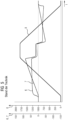
- figure 5 shows an exemplary time profile of a speed of a material web, an actual torque value and an actual power value according to the prior art.
- the representation of the actual torque value 6, the actual power value 7 and the speed 8 corresponds to that in figure 2 of the present document.
- the actual torque value 6 remains almost constant during the acceleration phase and is less than about half the nominal torque value of a corresponding drive unit 2.
- the speed 8 increases, the actual power value 7 continuously increases and while the speed 8 decreases, the actual power value continuously decreases.
- the actual power value 7 does not reach the rated power value of a corresponding drive unit 2 even at high speeds 8.
- there is at no time that is optimal in terms of torque or power. This results in a longer period of time required to achieve the desired movement.
- the invention relates to a method for moving a web 1 with conveyor means 3, 13 that can be driven by at least one drive unit 2.
- the invention also relates to a controller 15 and a machine 16 with at least one drive unit 2 and with conveyor means 3 that can be driven by the at least one drive unit 2 , 13.
- the invention further relates to a computer program 18 and a computer program product 19.
Landscapes
- Controlling Rewinding, Feeding, Winding, Or Abnormalities Of Webs (AREA)
- Control Of Electric Motors In General (AREA)
Claims (11)
- Procédé pour déplacer une bande (1) de matériau par des moyens (3, 13) de transport pouvant être entraînés par au moins une unité (2) d'entraînement, comprenant les stades de procédé suivants :- on détermine une valeur (6) réelle de couple et une valeur (7) réelle de puissance qu'utilise la au moins une unité (2) d'entraînement pour accélérer les moyens (3, 13) de transport,- on adapte les valeurs (11) de consigne de courant, qui sont prescrites à l'unité (2) d'entraînement, si la valeur (6) réelle de couple, qui a été déterminée, est plus petite en valeur absolue que le couple (4) pouvant être donné à l'avance ou si la valeur (7) réelle de puissance, qui a été déterminée, est plus petite que la puissance (5) pouvant être donnée à l'avance,- on détermine des valeurs de consigne de vitesse ou de vitesse de rotation au moyen d'un indicateur d'accélération, on compare lesdites valeurs de consigne de vitesse ou de vitesse de rotation aux valeurs réelles de vitesse ou de vitesse de rotation et, après une limitation de couple, on recalcule le couple pouvant être donné à l'avance et la puissance pouvant être donnée à l'avance en valeurs de consigne de courant,- on prescrit des valeurs (11) de consigne de courant à la au moins une unité (2) d'entraînement, de manière- à accélérer les moyens (3, 13) de transport par la au moins une unité (2) d'entraînement à un couple (4) pouvant être donné à l'avance, si une puissance nécessaire à cet effet est plus petite qu'une puissance (5) pouvant été donnée à l'avance de la au moins une unité (2) d'entraînement,- à accélérer les moyens (3, 13) de transport par la au moins une unité (2) d'entraînement à la puissance (5) donnée à l'avance, si un couple nécessaire à cet effet, est, en valeur absolue, plus petit que le couple (4) pouvant être donné à l'avance de la au moins une unité (2) d'entraînement,- on met fin à l'opération d'accélération, dès qu'un déplacement souhaité de la bande (1) de matériau a été atteint.
- Procédé suivant la revendication 1, dans lequel- le couple (4) pouvant être donné à l'avance de la au moins une unité (2) d'entraînement est le couple nominal de la au moins une unité (2) d'entraînement et- la puissance (5) pouvant être donnée à l'avance de la au moins une unité (2) d'entraînement est la puissance nominale de la au moins une unité (2) d'entraînement.
- Procédé suivant l'une des revendications précédentes, dans lequel- on réalise l'accélération des moyens (3, 13) de transport sous la forme d'un freinage du déplacement de la bande (1) de matériau et- on fait fonctionner la au moins une unité (2) d'entraînement en génératrice.
- Procédé suivant l'une des revendications précédentes, dans lequel- on réalise l'accélération des moyens (3, 13) de transport sous la forme d'un freinage du déplacement de la bande (1) de matériau et- on freine le déplacement de la bande (1) de matériau supplémentairement au moyen d'un frein (12).
- Procédé suivant l'une des revendications précédentes, comprenant les autres stades de procédé suivants :- on déroule et on enroule la bande (1) de matériau d'un ou sur un cylindre (13) d'enroulement, qui est compris par les moyens (3, 13) de transport et qui peut être entraîné par la au moins une unité (2) d'entraînement,- on détecte une épaisseur (14) d'enroulement de matériau de la bande (1) de matériau enroulée sur le cylindre (13) d'enroulement,- on met le couple nécessaire à l'accélération des moyens (3, 13) de transport, la puissance nécessaire pour accélérer les moyens (3, 13) de transport et/ou les valeurs (11) de consigne de courant en mémoire en fonction de l'épaisseur (14) de l'enroulement de matériau qui a été détectée.
- Procédé suivant la revendication 5, comprenant les autres stades de procédé suivants :- on détecte l'épaisseur (14) de l'enroulement de matériau de la bande (1) de matériau enroulée sur le cylindre (13) d'enroulement,- on utilise la dépendance mise en mémoire du couple nécessaire à l'accélération des moyens (3, 13) de transport, de la puissance nécessaire à l'accélération des moyens (3, 13) de transport et/ou des valeurs (11) de consigne de courant à l'épaisseur de l'enroulement de matériau, qui a été détectée, pour accélérer les moyens (3, 13) de transport jusqu'au déplacement souhaité de la bande (1) de matériau.
- Procédé suivant l'une des revendications précédentes comprenant les autres stades de procédé suivants :- on détermine le rapport du couple ou de la puissance pour chaque unité (2) d'entraînement, qui est nécessaire pour une accélération souhaitée, par rapport au couple ou à la puissance que l'unité (2) d'entraînement respective peut mettre à disposition au maximum,- si le rapport déterminé pour au moins une unité (2) d'entraînement est plus grand que 1 :- on détermine une accélération pouvant être réalisée au maximum de chaque unité (2) d'entraînement ayant le rapport déterminé le plus grand et- on accélère les moyens (3, 13) de transport à l'accélération pouvant être réalisée au maximum qui a été déterminé.
- Commande (15) d'une machine (16) ayant au moins une unité (2) d'entraînement et des moyens (3, 13) de transport pouvant être entraînés par la au moins une unité (2) d'entraînement,
dans laquelle la commande (15) a des moyens (17) pour effectuer un procédé suivant l'une des revendications 1 à 7. - Machine (16) comprenant- au moins une unité (2) d'entraînement,- des moyens (3, 13) de transport pouvant être entraînés par la au moins une unité (2) d'entraînement et- une commande (15), constituée suivant la revendication 8.
- Programme (18) d'ordinateur pour effectuer un procédé suivant l'une des revendications 1 à 7, lorsqu'il se déroule dans une commande (15) suivant la revendication 8.
- Produit (19) de programme d'ordinateur, sur lequel un programme (18) d'ordinateur suivant la revendication 10 est mis en mémoire.
Applications Claiming Priority (2)
| Application Number | Priority Date | Filing Date | Title |
|---|---|---|---|
| DE102011083574A DE102011083574A1 (de) | 2011-09-28 | 2011-09-28 | Verfahren und Vorrichtung zum Bewegen einer Warenbahn |
| PCT/EP2012/067285 WO2013045239A1 (fr) | 2011-09-28 | 2012-09-05 | Procédé et dispositif permettant de déplacer une bande de matériau |
Publications (3)
| Publication Number | Publication Date |
|---|---|
| EP2729397A1 EP2729397A1 (fr) | 2014-05-14 |
| EP2729397B1 EP2729397B1 (fr) | 2019-05-01 |
| EP2729397B2 true EP2729397B2 (fr) | 2023-06-07 |
Family
ID=47008483
Family Applications (1)
| Application Number | Title | Priority Date | Filing Date |
|---|---|---|---|
| EP12769953.6A Active EP2729397B2 (fr) | 2011-09-28 | 2012-09-05 | Procédé et dispositif permettant de déplacer une bande de matériau |
Country Status (6)
| Country | Link |
|---|---|
| EP (1) | EP2729397B2 (fr) |
| CN (1) | CN103842276B (fr) |
| DE (1) | DE102011083574A1 (fr) |
| ES (1) | ES2739624T3 (fr) |
| FI (1) | FI2729397T4 (fr) |
| WO (1) | WO2013045239A1 (fr) |
Families Citing this family (3)
| Publication number | Priority date | Publication date | Assignee | Title |
|---|---|---|---|---|
| WO2015113562A1 (fr) * | 2014-02-03 | 2015-08-06 | González-Villar Juan Carlos | Système d'entraînement destiné à des dispositifs de transport, d'extrusion, de poussée, de traction, à des applications de synchronisation et à des enrouleurs axiaux |
| EP3173887A1 (fr) * | 2015-11-24 | 2017-05-31 | Siemens Aktiengesellschaft | Procédé de déplacement d'un entraînement linéaire, entraînement linéaire et machine d'emballage ou de production |
| DE102019127838A1 (de) * | 2019-10-15 | 2021-04-15 | Reifenhäuser GmbH & Co. KG Maschinenfabrik | Verfahren zum Umwickeln einer aufgerollten Warenbahn und Umwickelvorrichtung |
Family Cites Families (11)
| Publication number | Priority date | Publication date | Assignee | Title |
|---|---|---|---|---|
| DE1189182B (de) * | 1961-08-15 | 1965-03-18 | Licentia Gmbh | Insbesondere fuer ein Bandwalzwerk vorgesehener Mehrmotorenantrieb |
| US3725755A (en) * | 1969-11-27 | 1973-04-03 | Vanguard | Systems for driving reels at controlled speed and power and improved apparatus for effecting such driving |
| US4519039A (en) * | 1982-07-23 | 1985-05-21 | Westinghouse Electric Corp. | Digital coil diameter function generator and reel motor drive system embodying the same |
| DE3731214A1 (de) * | 1987-09-17 | 1989-03-30 | Koenig & Bauer Ag | Vorrichtung fuer das gesteuerte zufuehren von bandmaterial zu druckmaschinen, sowie ein verfahren und eine vorrichtung zur durchfuehrung des verfahrens zur regelung eines entsprechenden steuersignals |
| JP2598968B2 (ja) * | 1988-06-13 | 1997-04-09 | 津田駒工業株式会社 | 巻取機械の制御装置 |
| JP3526372B2 (ja) * | 1996-06-13 | 2004-05-10 | 富士電機システムズ株式会社 | 巻取設備の制御方法 |
| DE102004004759B4 (de) * | 2004-01-30 | 2006-03-09 | Koenig & Bauer Ag | Antrieb für einen Rollenwechsler |
| FI120432B (fi) | 2007-02-05 | 2009-10-15 | Abb Oy | Menetelmä sähkökäytön ohjaamiseksi |
| DE102007007988A1 (de) * | 2007-02-17 | 2008-08-28 | Robert Bosch Gmbh | Verfahren und Vorrichtung zur Reibkompensation |
| FI125653B (fi) * | 2008-09-29 | 2015-12-31 | Valmet Technologies Inc | Kuiturainakoneen osan ja/tai laitteen sähkökäyttöjärjestely ja menetelmä kuiturainakoneen osan ja/tai laitteen sähkökäyttöjärjestelyn ohjaamiseksi |
| FI122609B (fi) | 2009-01-12 | 2012-04-13 | Abb Oy | Menetelmä, laitteisto ja tietokoneohjelmatuote aukirullaimen yhteydessä |
-
2011
- 2011-09-28 DE DE102011083574A patent/DE102011083574A1/de not_active Ceased
-
2012
- 2012-09-05 ES ES12769953T patent/ES2739624T3/es active Active
- 2012-09-05 EP EP12769953.6A patent/EP2729397B2/fr active Active
- 2012-09-05 CN CN201280047420.4A patent/CN103842276B/zh active Active
- 2012-09-05 WO PCT/EP2012/067285 patent/WO2013045239A1/fr not_active Ceased
- 2012-09-05 FI FIEP12769953.6T patent/FI2729397T4/de active
Also Published As
| Publication number | Publication date |
|---|---|
| EP2729397B1 (fr) | 2019-05-01 |
| DE102011083574A1 (de) | 2013-03-28 |
| FI2729397T4 (en) | 2024-01-29 |
| EP2729397A1 (fr) | 2014-05-14 |
| CN103842276A (zh) | 2014-06-04 |
| CN103842276B (zh) | 2016-03-09 |
| WO2013045239A1 (fr) | 2013-04-04 |
| ES2739624T3 (es) | 2020-02-03 |
Similar Documents
| Publication | Publication Date | Title |
|---|---|---|
| DE112011100347B4 (de) | Motorsteuervorrichtung | |
| EP2093419A2 (fr) | Procédé de régulation d'une éolienne et éolienne | |
| DE10024120A1 (de) | Rollenwechsler mit Motorbremse | |
| DE102010044901A1 (de) | Verfahren zum Betreiben einer Kreuzspulen herstellenden Textilmaschine und Kreuzspulen herstellende Textilmaschine | |
| DE3336945A1 (de) | Aufzuganlage | |
| EP2729397B2 (fr) | Procédé et dispositif permettant de déplacer une bande de matériau | |
| EP1820963A2 (fr) | Procédé de commande d'une éolienne | |
| EP3102988B1 (fr) | Système d'entraînement destiné à des dispositifs de transport, d'extrusion, de poussée, de traction, à des applications de synchronisation et à des enrouleurs axiaux | |
| EP1916416A2 (fr) | Procédé de fonctionnement d'une éolienne | |
| EP3292301A1 (fr) | Procédé pour faire fonctionner une éolienne | |
| DE102008040008A1 (de) | Verfahren zum Aussteuern und/oder Ausregeln einer Rutschbewegung einer Rolle relativ zu einem Band, Steuer- und/oder Regeleinrichtung, Maschinenlesbarer Programmcode, Speichermedium und Industrieanlage | |
| EP3838652B1 (fr) | Système d'entraînement pour un véhicule, procédé de fonctionnement d'entraînement ainsi que véhicule pourvu d'un système d'entraînement | |
| DE4126392C1 (en) | Appts. for spooling up fibres, preventing slippage and power fluctuations - includes controlling spooling speed by regulating spool spindle revolutions acccording to contact roller speed | |
| EP0061646B1 (fr) | Dispositif d'arrêt pour une commande électrique d'un arbre de démarrage d'une bobine comme un moteur à courant alternatif triphasé à vitesse variable | |
| DE102014001249A1 (de) | Antriebssystem für Zentrumswickler | |
| EP3830945B2 (fr) | Dispositif de transport à courroie ainsi que procédé d'arrêt d'une courroie d'un dispositif de transport à courroie | |
| EP2911259B1 (fr) | Utilisation d'un entraînement à régime régulé pour la stabilisation du réseau | |
| DE3040105C2 (de) | Verfahren zur Regelung der Drehzahl eines an einen Zwischenkreis-Umrichter angeschlossenen Drehstrom-Asynchronmotors und Vorrichtung zur Durchführung des Verfahrens | |
| DE202005020612U1 (de) | Vorrichtung zum Betrieb von Anlagen bei Netzspannungsausfällen | |
| EP2186187A2 (fr) | Procédé pour commander l'arrêt d'une machine asynchrone | |
| DE102013224324A1 (de) | Verfahren zum Betrieb einer Bahnbearbeitungsmaschine mit fliegendem Rollenwechsel | |
| DE102014103027A1 (de) | Nachführregler für eine U/f-gesteuerte Asynchronmaschine | |
| DE102014010336A1 (de) | Antriebssystem für Förder-, Extruder-, Schub -, Zugeinrichtungen, Gleichlaufanwendungen | |
| DE102019116671A1 (de) | Spinnmaschine sowie Verfahren zum Betreiben einer Spinnstelle einer Spinnmaschine | |
| AT523332B1 (de) | Verfahren zum Verbinden einer elektrischen Asynchronmaschine eines Triebstranges mit einem elektrischen Netz |
Legal Events
| Date | Code | Title | Description |
|---|---|---|---|
| PUAI | Public reference made under article 153(3) epc to a published international application that has entered the european phase |
Free format text: ORIGINAL CODE: 0009012 |
|
| 17P | Request for examination filed |
Effective date: 20140210 |
|
| AK | Designated contracting states |
Kind code of ref document: A1 Designated state(s): AL AT BE BG CH CY CZ DE DK EE ES FI FR GB GR HR HU IE IS IT LI LT LU LV MC MK MT NL NO PL PT RO RS SE SI SK SM TR |
|
| TPAC | Observations filed by third parties |
Free format text: ORIGINAL CODE: EPIDOSNTIPA |
|
| DAX | Request for extension of the european patent (deleted) | ||
| STAA | Information on the status of an ep patent application or granted ep patent |
Free format text: STATUS: EXAMINATION IS IN PROGRESS |
|
| RAP1 | Party data changed (applicant data changed or rights of an application transferred) |
Owner name: SIEMENS AKTIENGESELLSCHAFT |
|
| 17Q | First examination report despatched |
Effective date: 20170824 |
|
| GRAP | Despatch of communication of intention to grant a patent |
Free format text: ORIGINAL CODE: EPIDOSNIGR1 |
|
| STAA | Information on the status of an ep patent application or granted ep patent |
Free format text: STATUS: GRANT OF PATENT IS INTENDED |
|
| INTG | Intention to grant announced |
Effective date: 20181212 |
|
| GRAS | Grant fee paid |
Free format text: ORIGINAL CODE: EPIDOSNIGR3 |
|
| GRAA | (expected) grant |
Free format text: ORIGINAL CODE: 0009210 |
|
| STAA | Information on the status of an ep patent application or granted ep patent |
Free format text: STATUS: THE PATENT HAS BEEN GRANTED |
|
| AK | Designated contracting states |
Kind code of ref document: B1 Designated state(s): AL AT BE BG CH CY CZ DE DK EE ES FI FR GB GR HR HU IE IS IT LI LT LU LV MC MK MT NL NO PL PT RO RS SE SI SK SM TR |
|
| REG | Reference to a national code |
Ref country code: GB Ref legal event code: FG4D Free format text: NOT ENGLISH |
|
| REG | Reference to a national code |
Ref country code: CH Ref legal event code: EP Ref country code: AT Ref legal event code: REF Ref document number: 1126653 Country of ref document: AT Kind code of ref document: T Effective date: 20190515 |
|
| REG | Reference to a national code |
Ref country code: DE Ref legal event code: R096 Ref document number: 502012014701 Country of ref document: DE |
|
| REG | Reference to a national code |
Ref country code: IE Ref legal event code: FG4D Free format text: LANGUAGE OF EP DOCUMENT: GERMAN |
|
| REG | Reference to a national code |
Ref country code: SE Ref legal event code: TRGR |
|
| REG | Reference to a national code |
Ref country code: NL Ref legal event code: MP Effective date: 20190501 |
|
| REG | Reference to a national code |
Ref country code: LT Ref legal event code: MG4D |
|
| PG25 | Lapsed in a contracting state [announced via postgrant information from national office to epo] |
Ref country code: AL Free format text: LAPSE BECAUSE OF FAILURE TO SUBMIT A TRANSLATION OF THE DESCRIPTION OR TO PAY THE FEE WITHIN THE PRESCRIBED TIME-LIMIT Effective date: 20190501 Ref country code: PT Free format text: LAPSE BECAUSE OF FAILURE TO SUBMIT A TRANSLATION OF THE DESCRIPTION OR TO PAY THE FEE WITHIN THE PRESCRIBED TIME-LIMIT Effective date: 20190901 Ref country code: NO Free format text: LAPSE BECAUSE OF FAILURE TO SUBMIT A TRANSLATION OF THE DESCRIPTION OR TO PAY THE FEE WITHIN THE PRESCRIBED TIME-LIMIT Effective date: 20190801 Ref country code: HR Free format text: LAPSE BECAUSE OF FAILURE TO SUBMIT A TRANSLATION OF THE DESCRIPTION OR TO PAY THE FEE WITHIN THE PRESCRIBED TIME-LIMIT Effective date: 20190501 Ref country code: NL Free format text: LAPSE BECAUSE OF FAILURE TO SUBMIT A TRANSLATION OF THE DESCRIPTION OR TO PAY THE FEE WITHIN THE PRESCRIBED TIME-LIMIT Effective date: 20190501 Ref country code: LT Free format text: LAPSE BECAUSE OF FAILURE TO SUBMIT A TRANSLATION OF THE DESCRIPTION OR TO PAY THE FEE WITHIN THE PRESCRIBED TIME-LIMIT Effective date: 20190501 |
|
| PG25 | Lapsed in a contracting state [announced via postgrant information from national office to epo] |
Ref country code: RS Free format text: LAPSE BECAUSE OF FAILURE TO SUBMIT A TRANSLATION OF THE DESCRIPTION OR TO PAY THE FEE WITHIN THE PRESCRIBED TIME-LIMIT Effective date: 20190501 Ref country code: BG Free format text: LAPSE BECAUSE OF FAILURE TO SUBMIT A TRANSLATION OF THE DESCRIPTION OR TO PAY THE FEE WITHIN THE PRESCRIBED TIME-LIMIT Effective date: 20190801 Ref country code: LV Free format text: LAPSE BECAUSE OF FAILURE TO SUBMIT A TRANSLATION OF THE DESCRIPTION OR TO PAY THE FEE WITHIN THE PRESCRIBED TIME-LIMIT Effective date: 20190501 Ref country code: GR Free format text: LAPSE BECAUSE OF FAILURE TO SUBMIT A TRANSLATION OF THE DESCRIPTION OR TO PAY THE FEE WITHIN THE PRESCRIBED TIME-LIMIT Effective date: 20190802 |
|
| PG25 | Lapsed in a contracting state [announced via postgrant information from national office to epo] |
Ref country code: IS Free format text: LAPSE BECAUSE OF FAILURE TO SUBMIT A TRANSLATION OF THE DESCRIPTION OR TO PAY THE FEE WITHIN THE PRESCRIBED TIME-LIMIT Effective date: 20190901 |
|
| REG | Reference to a national code |
Ref country code: DE Ref legal event code: R026 Ref document number: 502012014701 Country of ref document: DE |
|
| PG25 | Lapsed in a contracting state [announced via postgrant information from national office to epo] |
Ref country code: EE Free format text: LAPSE BECAUSE OF FAILURE TO SUBMIT A TRANSLATION OF THE DESCRIPTION OR TO PAY THE FEE WITHIN THE PRESCRIBED TIME-LIMIT Effective date: 20190501 Ref country code: DK Free format text: LAPSE BECAUSE OF FAILURE TO SUBMIT A TRANSLATION OF THE DESCRIPTION OR TO PAY THE FEE WITHIN THE PRESCRIBED TIME-LIMIT Effective date: 20190501 Ref country code: SK Free format text: LAPSE BECAUSE OF FAILURE TO SUBMIT A TRANSLATION OF THE DESCRIPTION OR TO PAY THE FEE WITHIN THE PRESCRIBED TIME-LIMIT Effective date: 20190501 Ref country code: CZ Free format text: LAPSE BECAUSE OF FAILURE TO SUBMIT A TRANSLATION OF THE DESCRIPTION OR TO PAY THE FEE WITHIN THE PRESCRIBED TIME-LIMIT Effective date: 20190501 Ref country code: RO Free format text: LAPSE BECAUSE OF FAILURE TO SUBMIT A TRANSLATION OF THE DESCRIPTION OR TO PAY THE FEE WITHIN THE PRESCRIBED TIME-LIMIT Effective date: 20190501 |
|
| PLBI | Opposition filed |
Free format text: ORIGINAL CODE: 0009260 |
|
| REG | Reference to a national code |
Ref country code: ES Ref legal event code: FG2A Ref document number: 2739624 Country of ref document: ES Kind code of ref document: T3 Effective date: 20200203 |
|
| PG25 | Lapsed in a contracting state [announced via postgrant information from national office to epo] |
Ref country code: SM Free format text: LAPSE BECAUSE OF FAILURE TO SUBMIT A TRANSLATION OF THE DESCRIPTION OR TO PAY THE FEE WITHIN THE PRESCRIBED TIME-LIMIT Effective date: 20190501 |
|
| PLAX | Notice of opposition and request to file observation + time limit sent |
Free format text: ORIGINAL CODE: EPIDOSNOBS2 |
|
| REG | Reference to a national code |
Ref country code: FI Ref legal event code: MDE Opponent name: VOITH PATENT GMBH |
|
| 26 | Opposition filed |
Opponent name: VOITH PATENT GMBH Effective date: 20200130 |
|
| PG25 | Lapsed in a contracting state [announced via postgrant information from national office to epo] |
Ref country code: TR Free format text: LAPSE BECAUSE OF FAILURE TO SUBMIT A TRANSLATION OF THE DESCRIPTION OR TO PAY THE FEE WITHIN THE PRESCRIBED TIME-LIMIT Effective date: 20190501 |
|
| TPAC | Observations filed by third parties |
Free format text: ORIGINAL CODE: EPIDOSNTIPA |
|
| PG25 | Lapsed in a contracting state [announced via postgrant information from national office to epo] |
Ref country code: PL Free format text: LAPSE BECAUSE OF FAILURE TO SUBMIT A TRANSLATION OF THE DESCRIPTION OR TO PAY THE FEE WITHIN THE PRESCRIBED TIME-LIMIT Effective date: 20190501 |
|
| PG25 | Lapsed in a contracting state [announced via postgrant information from national office to epo] |
Ref country code: MC Free format text: LAPSE BECAUSE OF FAILURE TO SUBMIT A TRANSLATION OF THE DESCRIPTION OR TO PAY THE FEE WITHIN THE PRESCRIBED TIME-LIMIT Effective date: 20190501 Ref country code: SI Free format text: LAPSE BECAUSE OF FAILURE TO SUBMIT A TRANSLATION OF THE DESCRIPTION OR TO PAY THE FEE WITHIN THE PRESCRIBED TIME-LIMIT Effective date: 20190501 |
|
| REG | Reference to a national code |
Ref country code: CH Ref legal event code: PL |
|
| PLBB | Reply of patent proprietor to notice(s) of opposition received |
Free format text: ORIGINAL CODE: EPIDOSNOBS3 |
|
| PG25 | Lapsed in a contracting state [announced via postgrant information from national office to epo] |
Ref country code: CH Free format text: LAPSE BECAUSE OF NON-PAYMENT OF DUE FEES Effective date: 20190930 Ref country code: LU Free format text: LAPSE BECAUSE OF NON-PAYMENT OF DUE FEES Effective date: 20190905 Ref country code: IE Free format text: LAPSE BECAUSE OF NON-PAYMENT OF DUE FEES Effective date: 20190905 Ref country code: LI Free format text: LAPSE BECAUSE OF NON-PAYMENT OF DUE FEES Effective date: 20190930 |
|
| REG | Reference to a national code |
Ref country code: BE Ref legal event code: MM Effective date: 20190930 |
|
| PG25 | Lapsed in a contracting state [announced via postgrant information from national office to epo] |
Ref country code: BE Free format text: LAPSE BECAUSE OF NON-PAYMENT OF DUE FEES Effective date: 20190930 |
|
| GBPC | Gb: european patent ceased through non-payment of renewal fee |
Effective date: 20190905 |
|
| PG25 | Lapsed in a contracting state [announced via postgrant information from national office to epo] |
Ref country code: GB Free format text: LAPSE BECAUSE OF NON-PAYMENT OF DUE FEES Effective date: 20190905 |
|
| REG | Reference to a national code |
Ref country code: DE Ref legal event code: R081 Ref document number: 502012014701 Country of ref document: DE Owner name: SIEMENS ENERGY GLOBAL GMBH & CO. KG, DE Free format text: FORMER OWNER: SIEMENS AKTIENGESELLSCHAFT, 80333 MUENCHEN, DE |
|
| RAP2 | Party data changed (patent owner data changed or rights of a patent transferred) |
Owner name: SIEMENS ENERGY GLOBAL GMBH & CO. KG |
|
| PG25 | Lapsed in a contracting state [announced via postgrant information from national office to epo] |
Ref country code: CY Free format text: LAPSE BECAUSE OF FAILURE TO SUBMIT A TRANSLATION OF THE DESCRIPTION OR TO PAY THE FEE WITHIN THE PRESCRIBED TIME-LIMIT Effective date: 20190501 |
|
| PG25 | Lapsed in a contracting state [announced via postgrant information from national office to epo] |
Ref country code: MT Free format text: LAPSE BECAUSE OF FAILURE TO SUBMIT A TRANSLATION OF THE DESCRIPTION OR TO PAY THE FEE WITHIN THE PRESCRIBED TIME-LIMIT Effective date: 20190501 Ref country code: HU Free format text: LAPSE BECAUSE OF FAILURE TO SUBMIT A TRANSLATION OF THE DESCRIPTION OR TO PAY THE FEE WITHIN THE PRESCRIBED TIME-LIMIT; INVALID AB INITIO Effective date: 20120905 |
|
| PG25 | Lapsed in a contracting state [announced via postgrant information from national office to epo] |
Ref country code: MK Free format text: LAPSE BECAUSE OF FAILURE TO SUBMIT A TRANSLATION OF THE DESCRIPTION OR TO PAY THE FEE WITHIN THE PRESCRIBED TIME-LIMIT Effective date: 20190501 |
|
| REG | Reference to a national code |
Ref country code: AT Ref legal event code: PC Ref document number: 1126653 Country of ref document: AT Kind code of ref document: T Owner name: SIEMENS ENERGY GLOBAL GMBH & CO. KG, DE Effective date: 20221018 |
|
| PGFP | Annual fee paid to national office [announced via postgrant information from national office to epo] |
Ref country code: ES Payment date: 20221219 Year of fee payment: 11 |
|
| PUAH | Patent maintained in amended form |
Free format text: ORIGINAL CODE: 0009272 |
|
| STAA | Information on the status of an ep patent application or granted ep patent |
Free format text: STATUS: PATENT MAINTAINED AS AMENDED |
|
| 27A | Patent maintained in amended form |
Effective date: 20230607 |
|
| AK | Designated contracting states |
Kind code of ref document: B2 Designated state(s): AL AT BE BG CH CY CZ DE DK EE ES FI FR GB GR HR HU IE IS IT LI LT LU LV MC MK MT NL NO PL PT RO RS SE SI SK SM TR |
|
| REG | Reference to a national code |
Ref country code: DE Ref legal event code: R102 Ref document number: 502012014701 Country of ref document: DE |
|
| PG25 | Lapsed in a contracting state [announced via postgrant information from national office to epo] |
Ref country code: ES Free format text: LAPSE BECAUSE OF FAILURE TO SUBMIT A TRANSLATION OF THE DESCRIPTION OR TO PAY THE FEE WITHIN THE PRESCRIBED TIME-LIMIT Effective date: 20230607 |
|
| REG | Reference to a national code |
Ref country code: SE Ref legal event code: NAV |
|
| REG | Reference to a national code |
Ref country code: SE Ref legal event code: RE72 Free format text: PRV HAR I BESLUT DEN 24 MAJ 2024 FOERKLARAT OEVERSAETTNING OCH AVGIFT FOER PUBLICERING MOTTAGNA I TID FOER EP 12769953.6 (2729397) I AENDRAD AVFATTNING. PATENTET HAR DAERMED FORTFARANDE VERKAN I SVERIGE. Effective date: 20240524 Ref country code: SE Ref legal event code: RPEO |
|
| PGFP | Annual fee paid to national office [announced via postgrant information from national office to epo] |
Ref country code: FR Payment date: 20240925 Year of fee payment: 13 |
|
| PGFP | Annual fee paid to national office [announced via postgrant information from national office to epo] |
Ref country code: IT Payment date: 20240924 Year of fee payment: 13 |
|
| REG | Reference to a national code |
Ref country code: ES Ref legal event code: FD2A Effective date: 20250425 |
|
| PG25 | Lapsed in a contracting state [announced via postgrant information from national office to epo] |
Ref country code: ES Free format text: LAPSE BECAUSE OF NON-PAYMENT OF DUE FEES Effective date: 20230906 |
|
| PGFP | Annual fee paid to national office [announced via postgrant information from national office to epo] |
Ref country code: FI Payment date: 20250925 Year of fee payment: 14 |
|
| PGFP | Annual fee paid to national office [announced via postgrant information from national office to epo] |
Ref country code: DE Payment date: 20250926 Year of fee payment: 14 |
|
| PGFP | Annual fee paid to national office [announced via postgrant information from national office to epo] |
Ref country code: AT Payment date: 20250917 Year of fee payment: 14 |
|
| PGFP | Annual fee paid to national office [announced via postgrant information from national office to epo] |
Ref country code: SE Payment date: 20250924 Year of fee payment: 14 |