EP2729397B2 - Method and apparatus for moving a material web - Google Patents
Method and apparatus for moving a material web Download PDFInfo
- Publication number
- EP2729397B2 EP2729397B2 EP12769953.6A EP12769953A EP2729397B2 EP 2729397 B2 EP2729397 B2 EP 2729397B2 EP 12769953 A EP12769953 A EP 12769953A EP 2729397 B2 EP2729397 B2 EP 2729397B2
- Authority
- EP
- European Patent Office
- Prior art keywords
- drive unit
- torque
- power
- acceleration
- conveyor means
- Prior art date
- Legal status (The legal status is an assumption and is not a legal conclusion. Google has not performed a legal analysis and makes no representation as to the accuracy of the status listed.)
- Active
Links
Images
Classifications
-
- B—PERFORMING OPERATIONS; TRANSPORTING
- B65—CONVEYING; PACKING; STORING; HANDLING THIN OR FILAMENTARY MATERIAL
- B65H—HANDLING THIN OR FILAMENTARY MATERIAL, e.g. SHEETS, WEBS, CABLES
- B65H23/00—Registering, tensioning, smoothing or guiding webs
- B65H23/04—Registering, tensioning, smoothing or guiding webs longitudinally
- B65H23/18—Registering, tensioning, smoothing or guiding webs longitudinally by controlling or regulating the web-advancing mechanism, e.g. mechanism acting on the running web
- B65H23/182—Registering, tensioning, smoothing or guiding webs longitudinally by controlling or regulating the web-advancing mechanism, e.g. mechanism acting on the running web in unwinding mechanisms or in connection with unwinding operations
- B65H23/185—Registering, tensioning, smoothing or guiding webs longitudinally by controlling or regulating the web-advancing mechanism, e.g. mechanism acting on the running web in unwinding mechanisms or in connection with unwinding operations motor-controlled
-
- B—PERFORMING OPERATIONS; TRANSPORTING
- B65—CONVEYING; PACKING; STORING; HANDLING THIN OR FILAMENTARY MATERIAL
- B65H—HANDLING THIN OR FILAMENTARY MATERIAL, e.g. SHEETS, WEBS, CABLES
- B65H23/00—Registering, tensioning, smoothing or guiding webs
- B65H23/04—Registering, tensioning, smoothing or guiding webs longitudinally
- B65H23/18—Registering, tensioning, smoothing or guiding webs longitudinally by controlling or regulating the web-advancing mechanism, e.g. mechanism acting on the running web
- B65H23/195—Registering, tensioning, smoothing or guiding webs longitudinally by controlling or regulating the web-advancing mechanism, e.g. mechanism acting on the running web in winding mechanisms or in connection with winding operations
- B65H23/198—Registering, tensioning, smoothing or guiding webs longitudinally by controlling or regulating the web-advancing mechanism, e.g. mechanism acting on the running web in winding mechanisms or in connection with winding operations motor-controlled (Controlling electrical drive motors therefor)
-
- B—PERFORMING OPERATIONS; TRANSPORTING
- B65—CONVEYING; PACKING; STORING; HANDLING THIN OR FILAMENTARY MATERIAL
- B65H—HANDLING THIN OR FILAMENTARY MATERIAL, e.g. SHEETS, WEBS, CABLES
- B65H2220/00—Function indicators
- B65H2220/02—Function indicators indicating an entity which is controlled, adjusted or changed by a control process, i.e. output
-
- B—PERFORMING OPERATIONS; TRANSPORTING
- B65—CONVEYING; PACKING; STORING; HANDLING THIN OR FILAMENTARY MATERIAL
- B65H—HANDLING THIN OR FILAMENTARY MATERIAL, e.g. SHEETS, WEBS, CABLES
- B65H2513/00—Dynamic entities; Timing aspects
- B65H2513/20—Acceleration or deceleration
-
- B—PERFORMING OPERATIONS; TRANSPORTING
- B65—CONVEYING; PACKING; STORING; HANDLING THIN OR FILAMENTARY MATERIAL
- B65H—HANDLING THIN OR FILAMENTARY MATERIAL, e.g. SHEETS, WEBS, CABLES
- B65H2515/00—Physical entities not provided for in groups B65H2511/00 or B65H2513/00
- B65H2515/70—Electrical or magnetic properties, e.g. electric power or current
Definitions
- the invention relates to a method for moving a web of material with conveying means that can be driven by at least one drive unit.
- the invention relates to a controller and a machine with at least one drive unit and with conveying means that can be driven by the at least one drive unit.
- the invention further relates to a computer program and a computer program product.
- Such a method and such devices are used in particular where machines move continuous webs of material by means of electrically driven rollers and cylinders.
- these cylinders and rollers have large masses of inertia that depend on the amount of material wound up, so that the time required for acceleration and braking can be in the range of several minutes.
- This ramp time mainly depends on the factors of friction and mass inertia.
- the mass inertia is strongly dependent on the amount of material wound up.
- a programmable controller is known by means of which a calibration between successive winding and unwinding processes of a tape as well as an automatic generation of a current reference value for a control of a motor of a winding or unwinding roller is made possible in real time.
- the controller includes a computing unit for determining the roller diameter and compensation for a deviation in the belt speed and inertia compensation.
- EP 1 958 905 A2 further describes a method and a device for compensating for friction in a winding machine. Furthermore, in EP 1 958 905 A2 discloses a control method for friction compensation in a winding machine.
- the object of the invention is to reduce the times for accelerating and decelerating a web of material using existing drives or to be able to use drives with lower power and torque limits for the same time requirements.
- this object is achieved by a method for moving a web of material with conveying means that can be driven by at least one drive unit according to the features of claim 1 .
- the method can be used in particular in paper, foil or steel processing machines in which continuous webs of material are moved by means of electrically drivable conveying means.
- These conveyors can be designed, for example, as rollers, cylinders, conveyor belts or the like and, together with the webs of material moved with them, can have a high mass inertia.
- the advantage of the method according to the present invention is the possibility of being able to quickly change the movement of a web. In particular when accelerating a material web, the process allows a movement that is optimal in terms of torque and performance. This is also possible when the mass inertia of the conveyor or the web changes, for example by winding the web onto the conveyor.
- the concept of acceleration is understood as a positive or negative change in speed, so that the speed can increase or decrease in absolute terms during an acceleration.
- the distinction is based on the fact that, particularly in the case of electric drives, the torque is the limiting variable for acceleration at low speeds or speeds.
- a drive unit can provide a comparatively high torque at a low speed or speed, whereas the power of the drive unit is comparatively low and increases proportionally to the speed or speed.
- the power of the drive unit is the limiting factor for acceleration.
- the drive unit can provide comparatively high power, with the torque reducing for increasing speeds or speeds.
- a torque and a power can now be specified, otherwise stored values can be used.
- the at least one drive unit requires a certain torque and a certain power to accelerate the conveying means and the material web.
- the method now provides for accelerating the conveying means with the definable torque if the power required for this is less than the definable power. If the amount of torque required for acceleration is smaller than the torque that can be specified, the conveying means are accelerated with the power that can be specified. In the case of real drives, brief overshoots can occur during which a greater torque than the specifiable torque or a higher power than the specifiable power is made available.
- the acceleration is accomplished by the drive unit, to which appropriate current setpoint values are specified.
- the specification of the desired current values can be preceded by further steps, such as specifying desired ramp times.
- the method also provides for ending the acceleration process as soon as a desired movement or speed of the material web has been reached. In particular, this can be the run-up of the material line up to a certain speed or the complete standstill of the material line.
- the predefinable power can be, for example, a specific percentage of the rated power of the at least one drive unit and the predefinable torque can be, for example, a specific percentage of the rated torque of the at least one drive unit.
- the predefinable torque of the at least one drive unit is the rated torque of the at least one drive unit and the predefinable power is the rated power of the at least one drive unit.
- the use of the nominal torque or the nominal power of the at least one drive unit allows the fastest possible acceleration of the funding.
- the funding - e.g. B. starting from standstill - accelerated using the rated torque until that speed or speed is reached for which the drive unit requires the rated power. From this speed, the conveyor can continue to be accelerated using the rated power, with the torque being reduced as the speed or speed increases. Finally, the acceleration process is terminated as soon as the desired movement of the material has been achieved.
- this acceleration of the web is achieved using the nominal power of the at least one drive unit, provided that the torque required for this is smaller than the nominal torque.
- the material web is decelerated by the at least one drive unit using the nominal power until the amount of torque required for this is equal to the nominal torque of the at least one drive unit.
- the material web is then further braked with the rated torque of the drive unit, the braking power now being less than the rated power of the at least one drive unit.
- the at least one drive unit can be designed, for example, in such a way that at least one rectifier, which rectifies an AC voltage of the supply network into an intermediate circuit voltage, at least one intermediate circuit capacitor and at least one inverter, which inverts the intermediate circuit voltage into an AC voltage of variable frequency, are provided. If a rectifier and multiple inverters are used, the inverters can have a greater total power than the rectifier, so that the power of the at least one drive unit is limited by the rectifier. In this case, the rated power of the at least one drive unit is given by the rated power of the rectifier.
- the method can be checked and fed back in such a way that the current setpoint values for the drive unit are corrected and adjusted if necessary.
- the actual values of the torque and the power of the at least one drive unit can be determined in particular by a converter that is comprised by the at least one drive unit.
- the acceleration of the conveying means is performed as a deceleration of the movement of the material web and the at least one drive unit is operated as a generator.
- the generator operation of a drive unit of the machine is particularly interesting with regard to environmental protection, energy savings and cost reduction. This is because when the conveyor is braked, its kinetic energy can be fed back into the power grid by the at least one drive unit in the form of electrical energy. Overall, the machine thus consumes less energy, which is synonymous with cost reduction and improved environmental protection.
- the acceleration of the conveying means is performed as a deceleration of the movement of the web of material, and the movement of the web of material is additionally decelerated by means of a brake.
- Greater acceleration of the conveyor can be achieved through the use of a brake, resulting in increased productivity of the machine since the time to decelerate the machine to a desired movement can be reduced. Consequently, the cost can be further reduced.
- the conveying means comprise a winding cylinder, which can also be designed as a roller or some other device for winding up a web of material.
- the web of material is wound up or unwound onto the winding cylinder, and since the web of material itself has a specific thickness, the material wound up on the cylinder has a specific winding thickness of the material, which is detected.
- the torque required for accelerating the conveying means, the torque required for accelerating the conveying means and/or the desired current values are recorded and stored for a detected winding thickness. This can take place, for example, in a controller in which the dependency of the variables mentioned on the recorded material winding thickness of the material web wound onto the winding cylinder is present.
- the stored information can be used when detecting a specific roll thickness currently present on the cylinder.
- a learning process thus takes place, and a machine on which the method is applied is characterized by a certain "intelligence". This is particularly advantageous if different types of webs are used which have different properties, thicknesses or masses and the dependency mentioned is stored separately for each of the different webs of material.
- the stated ratio of the required torque in relation to the maximum torque that can be achieved by a drive unit or the corresponding ratio in relation to the power outputs expresses whether the drive unit under consideration is able to bring about the desired acceleration. If this is not the case and the desired acceleration cannot be achieved, the determined ratio is greater than 1.
- the ratio for each of the drive units determined. If one of the determined ratios is greater than 1, the maximum acceleration that can be achieved is determined for the drive unit that has the largest determined ratio and is therefore most overwhelmed. Finally, the funds are accelerated with the determined maximum acceleration that can be achieved. So that means that the drive unit with the largest determined ratio and which is most overwhelmed specifies the acceleration of the conveyor.
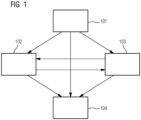
- figure 1 shows a flow chart of the method according to the present invention for moving a web 1.
- step 101 a desired movement of the web 1 is compared with the current movement of the web 1 . If the current movement of the web of material 1 is equal to the desired movement of the web of material 1, step 104 is carried out, in which the method is ended. However, if the current movement and the desired movement of the web of material 1 are different, the web of material 1 is accelerated by means of conveying means 3 , 13 that can be driven by at least one drive unit 2 . To this end, a distinction is made between two cases, for which corresponding desired current values 11 are specified for the at least one drive unit 2 in each case.
- step 102 the conveying means 3, 13 are accelerated by the at least one drive unit 2 with a specifiable torque 4 if the power required for this is less than a specifiable power 5 of the at least one drive unit 2.
- step 103 the conveying means 3, 13 are accelerated by the at least one drive unit 2 with the specifiable power 5 if the amount of torque required for this is smaller than the specifiable torque 4 of the at least one drive unit 2. If step 102 or 103 has been carried out, step 103 or 102 can then be carried out or the acceleration process is ended in accordance with 104 as soon as a desired movement of the material web 1 has been achieved.
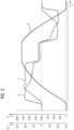
- figure 2 shows an exemplary time course of the speed 8 of a web 1, an actual torque value 6 and an actual power value 7 according to the method of the present invention.
- the time is plotted on the abscissa and the speed 8 of a material web 1 is plotted on the ordinate axis with a scale from 0 to 2000.
- the ordinate axis also shows an actual torque value 6 and a Actual power value 7 plotted.
- the two latter variables are expressed as a relative variable in % in relation to the corresponding nominal values of a drive unit 2 , with the drive unit 2 being able to accelerate conveying means 3 , 13 which move the material web 1 . for in figure 2
- the nominal power of the drive unit 2 is reached, so that with a further increasing speed 8 the actual power value 7 corresponds to the nominal power of the drive unit 2 and the actual torque value 6 is reduced with increasing speed 8 .
- the acceleration of the web 1 and the conveyors 3, 13 is finally terminated as soon as the desired movement, ie a desired speed 8 has been reached. In order to maintain a certain speed 8, then only that power and that torque are required, which the occurring compensate for friction losses.
- the drive unit 2 In order to decelerate a moving web 1, ie to accelerate it in the opposite direction to the direction of movement, the drive unit 2 first uses the rated power of the drive unit as the actual power value 7, with an actual torque value 6 being used, the absolute value of which is smaller than the torque Rated value of the drive unit 2.
- the actual power value 7 is kept constant as the speed 8 decreases, with the actual torque value increasing until the rated torque value of the drive unit 2 is reached.
- the actual torque value 6 is now kept constant equal to the nominal torque of the drive unit 2 and the actual power value 7 is reduced as the speed 8 decreases.
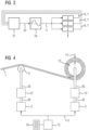
- figure 3 shows a block diagram of a first embodiment of the method according to the present invention.
- nominal current values 11 are specified by a ramp-function generator 24 .
- the setpoints can either be transferred directly to all drive units 2 or via a setpoint scale or via a setpoint cascade.
- the ramp-function generator 24 can also be designed as a ramp generator or the like.
- the drives 2 can carry out a movement using a respective actual torque value 6 and a respective actual power value 7 which are registered by a ramp adaptation 21 .
- a value for the acceleration rate 22 is thus determined, which is transmitted to the ramp-function generator 24 . This in turn generates the desired current values 11 which are specified for the drive units 2 .
- FIG 4 shows a block diagram of a first embodiment of the machine according to the present invention.
- a web of material 1 is moved over a roller 3 to a winding cylinder 13 on which the web of material 1 is wound.
- the material web 1 wound on the winding cylinder 13 has a material winding thickness 14 .
- the roller 3 and the winding cylinder 13 are each driven via a drive shaft 20 which is each provided with a brake 12 and is driven by a drive unit 2 .
- the respective drive units 2 receive desired current values 11 from a controller 15 on which a computer program 18 runs while the method of the present invention is being carried out.
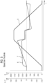
- figure 5 shows an exemplary time profile of a speed of a material web, an actual torque value and an actual power value according to the prior art.
- the representation of the actual torque value 6, the actual power value 7 and the speed 8 corresponds to that in figure 2 of the present document.
- the actual torque value 6 remains almost constant during the acceleration phase and is less than about half the nominal torque value of a corresponding drive unit 2.
- the speed 8 increases, the actual power value 7 continuously increases and while the speed 8 decreases, the actual power value continuously decreases.
- the actual power value 7 does not reach the rated power value of a corresponding drive unit 2 even at high speeds 8.
- there is at no time that is optimal in terms of torque or power. This results in a longer period of time required to achieve the desired movement.
- the invention relates to a method for moving a web 1 with conveyor means 3, 13 that can be driven by at least one drive unit 2.
- the invention also relates to a controller 15 and a machine 16 with at least one drive unit 2 and with conveyor means 3 that can be driven by the at least one drive unit 2 , 13.
- the invention further relates to a computer program 18 and a computer program product 19.
Landscapes
- Controlling Rewinding, Feeding, Winding, Or Abnormalities Of Webs (AREA)
- Control Of Electric Motors In General (AREA)
Description
Die Erfindung betrifft ein Verfahren zum Bewegen einer Warenbahn mit durch zumindest eine Antriebseinheit antreibbaren Fördermitteln.The invention relates to a method for moving a web of material with conveying means that can be driven by at least one drive unit.
Weiterhin betrifft die Erfindung eine Steuerung und eine Maschine mit zumindest einer Antriebseinheit und mit durch die zumindest eine Antriebseinheit antreibbaren Fördermitteln. Weiter betrifft die Erfindung ein Computerprogramm und ein Computerprogrammprodukt.Furthermore, the invention relates to a controller and a machine with at least one drive unit and with conveying means that can be driven by the at least one drive unit. The invention further relates to a computer program and a computer program product.
Ein derartiges Verfahren und derartige Vorrichtungen kommen insbesondere dort zum Einsatz, wo Maschinen durchlaufende Warenbahnen mittels elektrisch angetriebener Walzen und Zylinder bewegen. Diese Zylinder und Walzen haben vor allem bei papier-, folien- und stahlverarbeitenden Maschinen große, von der Menge des aufgewickelten Materials abhängige Massenträgheiten, so dass die Zeit zum Beschleunigen und Abbremsen im Bereich von mehreren Minuten liegen kann. Um die Zeiten mit Produktion zu verlängern, ist es sinnvoll die kürzest möglichen Rampenzeiten zum Beschleunigen und Abbremsen zu verwenden. Diese Rampenzeit hängt hauptsächlich von den Faktoren Reibung und Massenträgheit ab. Die Massenträgheit ist vor allem bei Wicklern (Auf- und Abwicklern) stark von der Menge des aufgewickelten Materials abhängig. Die Beschleunigungs- und Abbremswerte wurden bisher auf jeweils einen solchen Wert eingestellt, dass die Maschine elektrisch und mechanisch nicht überlastet wird.Such a method and such devices are used in particular where machines move continuous webs of material by means of electrically driven rollers and cylinders. Especially in paper, foil and steel processing machines, these cylinders and rollers have large masses of inertia that depend on the amount of material wound up, so that the time required for acceleration and braking can be in the range of several minutes. In order to extend the times with production, it makes sense to use the shortest possible ramp times for acceleration and deceleration. This ramp time mainly depends on the factors of friction and mass inertia. In the case of winders (winders and unwinders), the mass inertia is strongly dependent on the amount of material wound up. Up to now, the acceleration and deceleration values have each been set to such a value that the machine is not overloaded either electrically or mechanically.
Aus der
Der Erfindung liegt die Aufgabe zugrunde, Zeiten zum Beschleunigen und Abbremsen einer Warenbahn durch vorhandene Antriebe zu verringern bzw. bei gleichen zeitlichen Anforderungen Antriebe mit geringeren Leistungs- und Drehmomentgrenzen verwenden zu können.The object of the invention is to reduce the times for accelerating and decelerating a web of material using existing drives or to be able to use drives with lower power and torque limits for the same time requirements.
Diese Aufgabe wird erfindungsgemäß durch ein Verfahren zum Bewegen einer Warenbahn mit durch zumindest eine Antriebseinheit antreibbaren Fördermitteln nach den Merkmalen des Anspruchs 1 gelöst.According to the invention, this object is achieved by a method for moving a web of material with conveying means that can be driven by at least one drive unit according to the features of
Diese Aufgabe wird weiter gelöst durch eine Steuerung gemäß Anspruch 8, eine Maschine gemäß Anspruch 9, ein Computerprogramm gemäß Anspruch 10 und ein Computerprogrammprodukt gemäß Anspruch 11.This object is further achieved by a controller according to
Das Verfahren kann insbesondere bei papier-, folien- bzw. stahlverarbeitenden Maschinen eingesetzt werden, bei welchen durchlaufende Warenbahnen mittels elektrisch antreibbaren Fördermitteln bewegt werden. Diese Fördermittel können beispielsweise als Walzen, Zylinder, Förderbänder oder dergleichen ausgeführt sein und können zusammen mit den damit bewegten Warenbahnen eine große Massenträgheit aufweisen. Der Vorteil des Verfahrens gemäß der vorliegenden Erfindung ist die Möglichkeit, die Bewegung einer Warenbahn schnell verändern zu können. Insbesondere bei der Beschleunigung einer Warenbahn erlaubt das Verfahren eine drehmoment- und leistungsoptimale Bewegung. Dies ist auch dann möglich, wenn sich die Massenträgheit der Fördermittel oder der Warenbahn ändert, beispielsweise durch Aufwickeln der Warenbahn auf die Fördermittel. Dabei wird der Begriff der Beschleunigung als positive bzw. negative Geschwindigkeitsänderung verstanden, so dass die Geschwindigkeit während einer Beschleunigung betragsmäßig größer oder kleiner werden kann.The method can be used in particular in paper, foil or steel processing machines in which continuous webs of material are moved by means of electrically drivable conveying means. These conveyors can be designed, for example, as rollers, cylinders, conveyor belts or the like and, together with the webs of material moved with them, can have a high mass inertia. The advantage of the method according to the present invention is the possibility of being able to quickly change the movement of a web. In particular when accelerating a material web, the process allows a movement that is optimal in terms of torque and performance. This is also possible when the mass inertia of the conveyor or the web changes, for example by winding the web onto the conveyor. The concept of acceleration is understood as a positive or negative change in speed, so that the speed can increase or decrease in absolute terms during an acceleration.
Gemäß dem vorliegenden Verfahren werden bei der Beschleunigung, einer Warenbahn zwei Fälle unterschieden. Der Unterscheidung liegt dabei die Tatsache zugrunde, dass insbesondere bei elektrischen Antrieben bei einer geringen Geschwindigkeit oder Drehzahl das Drehmoment die begrenzende Größe der Beschleunigung ist. D.h. bei geringer Drehzahl oder Geschwindigkeit kann eine Antriebseinheit vergleichsweise großes Drehmoment zur Verfügung stellen, wohingegen die Leistung der Antriebseinheit vergleichsweise gering ist und proportional zur Geschwindigkeit oder Drehzahl wächst. Für größere Geschwindigkeiten oder Drehzahlen ist jedoch die Leistung der Antriebseinheit die begrenzende Größe der Beschleunigung. In diesem Fall kann die Antriebseinheit eine vergleichsweise große Leistung zur Verfügung stellen, wobei sich das Drehmoment für zunehmende Geschwindigkeiten oder Drehzahlen verringert.According to the present method, two cases are distinguished when accelerating a material web. The distinction is based on the fact that, particularly in the case of electric drives, the torque is the limiting variable for acceleration at low speeds or speeds. This means that a drive unit can provide a comparatively high torque at a low speed or speed, whereas the power of the drive unit is comparatively low and increases proportionally to the speed or speed. For higher speeds or speeds, however, the power of the drive unit is the limiting factor for acceleration. In this case, the drive unit can provide comparatively high power, with the torque reducing for increasing speeds or speeds.
Erfindungsgemäß kann nun ein Drehmoment und eine Leistung vorgegeben werden, andernfalls können hinterlegte Werte verwendet werden. Für die Beschleunigung der Fördermittel und der Warenbahn benötigt die zumindest eine Antriebseinheit ein gewisses Drehmoment und eine gewisse Leistung. Das Verfahren sieht nun vor, die Fördermittel mit dem vorgebbaren Drehmoment zu beschleunigen, falls die dafür benötigte Leistung kleiner als die vorgebbare Leistung ist. Falls das für die Beschleunigung benötigte Drehmoment betragsmäßig kleiner als das vorgebbare Drehmoment ist, werden die Fördermittel mit der vorgebbaren Leistung beschleunigt. Dabei kann es bei realen Antrieben zu kurzzeitigen Überschwingern kommen, während denen ein größeres Drehmoment als das vorgebbare Drehmoment bzw. eine höhere Leistung als die vorgebbare Leistung zur Verfügung gestellt wird. Im Vergleich zu den bekannten Lösungen wird weniger Zeit für das Hoch- bzw. Herunterfahren einer Maschine mit durchlaufenden Warenbahnen benötigt, und es ergibt sich also eine zumindest nahezu optimale Rampenzeit, während der die Fördermittel beschleunigt werden. Dabei wird die Beschleunigung bewerkstelligt durch die Antriebseinheit, welcher entsprechende Strom-Sollwerte vorgegeben werden. Der Vorgabe der Strom-Sollwerte können weitere Schritte vorgeschalten sein, wie zum Beispiel eine Vorgabe von erwünschten Rampenzeiten. Das Verfahren sieht weiterhin vor, den Beschleunigungsvorgang zu beenden, sobald eine gewünschte Bewegung bzw. Geschwindigkeit der Warenbahn erreicht wurde. Dies kann insbesondere der Hochlauf der Warenbahn bis zu einer gewissen Geschwindigkeit oder der vollständige Stillstand der Warenbahn sein.According to the invention, a torque and a power can now be specified, otherwise stored values can be used. The at least one drive unit requires a certain torque and a certain power to accelerate the conveying means and the material web. The method now provides for accelerating the conveying means with the definable torque if the power required for this is less than the definable power. If the amount of torque required for acceleration is smaller than the torque that can be specified, the conveying means are accelerated with the power that can be specified. In the case of real drives, brief overshoots can occur during which a greater torque than the specifiable torque or a higher power than the specifiable power is made available. Compared to the known solutions, less time is required for the or shutting down a machine with webs of material running through is required, and there is therefore an at least almost optimal ramp time during which the funding means are accelerated. In this case, the acceleration is accomplished by the drive unit, to which appropriate current setpoint values are specified. The specification of the desired current values can be preceded by further steps, such as specifying desired ramp times. The method also provides for ending the acceleration process as soon as a desired movement or speed of the material web has been reached. In particular, this can be the run-up of the material line up to a certain speed or the complete standstill of the material line.
Für den Fall einer nachträglich erweiterbaren Maschine oder um anderen Gegebenheiten Rechnung zu tragen, kann die vorgebbare Leistung beispielsweise ein bestimmter Prozentsatz der Nennleistung der zumindest einen Antriebseinheit und das vorgebbare Drehmoment beispielsweise ein bestimmter Prozentsatz des Nenndrehmoments der zumindest einen Antriebseinheit sein.In the case of a machine that can be expanded later or to take other circumstances into account, the predefinable power can be, for example, a specific percentage of the rated power of the at least one drive unit and the predefinable torque can be, for example, a specific percentage of the rated torque of the at least one drive unit.
Bei einer vorteilhaften Ausgestaltung des Verfahrens ist das vorgebbare Drehmoment der zumindest einen Antriebseinheit das Nenndrehmoment der zumindest einen Antriebseinheit und die vorgebbare Leistung die Nennleistung der zumindest einen Antriebseinheit. Das Verwenden des Nenndrehmoments bzw. der Nennleistung der zumindest einen Antriebseinheit erlaubt dabei die schnellstmögliche Beschleunigung der Fördermittel. So werden die Fördermittel - z. B. ausgehend vom Stillstand - unter Verwendung des Nenndrehmoments beschleunigt, bis jene Geschwindigkeit oder Drehzahl erreicht wird, für welche die Antriebseinheit die Nennleistung benötigt. Ab dieser Drehzahl kann die Beschleunigung der Fördermittel unter Verwendung der Nennleistung fortgeführt werden, wobei das Drehmoment mit zunehmender Geschwindigkeit oder Drehzahl verringert wird. Schließlich wird der Beschleunigungsvorgang beendet, sobald die gewünschte Bewegung der Warenbahn erreicht wurde. Wird die Warenbahn bewegt und ist ein Abbremsen gewünscht, so wird diese als Abbremsen ausgeführte Beschleunigung der Warenbahn unter Verwendung der Nennleistung der zumindest einen Antriebseinheit erreicht, sofern das dafür benötigte Drehmoment betragsmäßig kleiner als das Nenndrehmoment ist. Für diesen Fall wird die Warenbahn durch die zumindest eine Antriebseinheit unter Verwendung der Nennleistung soweit abgebremst, bis das dafür benötigte Drehmoment betragsmäßig gleich dem Nenndrehmoment der zumindest einen Antriebseinheit ist. Anschließend wird die Warenbahn mit dem Nenndrehmoment der Antriebseinheit weiter gebremst, wobei die Bremsleistung nun kleiner als die Nennleistung der zumindest einen Antriebseinheit ist. Insgesamt ergibt sich somit eine nahezu optimale Rampenzeit, während der die Fördermittel beschleunigt werden und während der die zumindest eine Antriebseinheit die jeweils maximal mögliche Beschleunigung bewirkt. Folglich wird also weniger Zeit für das Hoch- bzw. Herunterfahren einer Maschine mit durchlaufenden Warenbahnen benötigt.In an advantageous embodiment of the method, the predefinable torque of the at least one drive unit is the rated torque of the at least one drive unit and the predefinable power is the rated power of the at least one drive unit. The use of the nominal torque or the nominal power of the at least one drive unit allows the fastest possible acceleration of the funding. The funding - e.g. B. starting from standstill - accelerated using the rated torque until that speed or speed is reached for which the drive unit requires the rated power. From this speed, the conveyor can continue to be accelerated using the rated power, with the torque being reduced as the speed or speed increases. Finally, the acceleration process is terminated as soon as the desired movement of the material has been achieved. If the web is moved and deceleration is desired, this acceleration of the web, executed as deceleration, is achieved using the nominal power of the at least one drive unit, provided that the torque required for this is smaller than the nominal torque. In this case, the material web is decelerated by the at least one drive unit using the nominal power until the amount of torque required for this is equal to the nominal torque of the at least one drive unit. The material web is then further braked with the rated torque of the drive unit, the braking power now being less than the rated power of the at least one drive unit. Overall, this results in an almost optimal ramp time, during which the conveying means are accelerated and during which the at least one drive unit brings about the maximum possible acceleration in each case. As a result, less time is required for starting up and shutting down a machine with continuous material webs.
Die zumindest eine Antriebseinheit kann beispielsweise der Gestalt sein, dass zumindest ein Gleichrichter, welcher eine Wechselspannung des Versorgungsnetzes in eine Zwischenkreisspannung gleichrichtet, zumindest ein Zwischenkreiskondensator und zumindest ein Wechselrichter, welcher die Zwischenkreisspannung in eine Wechselspannung veränderlicher Frequenz wechselrichtet, vorgesehen sind. Werden ein Gleichrichter und mehrere Wechselrichter verwendet, können die Wechselrichter eine größere Gesamtleistung haben als der Gleichrichter, so dass die Leistung der zumindest einen Antriebseinheit durch den Gleichrichter begrenzt wird. Für diesen Fall ist die Nennleistung der zumindest einen Antriebseinheit durch die Nennleistung des Gleichrichters gegeben. Denkbar ist auch der Einsatz von Motoren in der zumindest einen Antriebseinheit, die ein geringeres oder ein größeres Nenndrehmoment aufweisen als jenes, welches die Einheit aus Gleichrichter, Zwischenkreiskondensatoren und Wechselrichter bewerkstelligen kann. Das Nenndrehmoment der zumindest einen Antriebseinheit ist dann Unterberücksichtigung des schwächsten Glieds der zumindest einen Antriebseinheit zu bestimmen.The at least one drive unit can be designed, for example, in such a way that at least one rectifier, which rectifies an AC voltage of the supply network into an intermediate circuit voltage, at least one intermediate circuit capacitor and at least one inverter, which inverts the intermediate circuit voltage into an AC voltage of variable frequency, are provided. If a rectifier and multiple inverters are used, the inverters can have a greater total power than the rectifier, so that the power of the at least one drive unit is limited by the rectifier. In this case, the rated power of the at least one drive unit is given by the rated power of the rectifier. It is also conceivable to use motors in the at least one drive unit that have a lower or higher nominal torque than that which the unit made up of rectifier, intermediate circuit capacitors and inverter can achieve. The nominal torque of the at least one drive unit is then to be determined without taking into account the weakest link of the at least one drive unit.
Bei einer weiteren vorteilhaften Ausgestaltung des Verfahrens weist das Verfahren die folgenden weiteren Verfahrensschritte auf:
- Ermitteln von Istwerten des Drehmoments und der Leistung, welche die zumindest eine Antriebseinheit zum Beschleunigen der Fördermittel verwendet,
- Anpassen der Strom-Sollwerte, welche an die Antriebseinheit vorgegeben werden, falls der Istwert des Drehmoments betragsmäßig kleiner als das vorgebbare Drehmoment bzw. der Istwert der ermittelten Leistung kleiner als die vorgebbare Leistung ist.
- Determining actual values of the torque and the power, which the at least one drive unit uses to accelerate the conveying means,
- Adaptation of the current setpoints, which are specified to the drive unit if the actual value of the torque is smaller than the specified torque or the actual value of the determined power is smaller than the specified power.
Durch die Ermittlung der Istwerte des Drehmoments und der Leistung und deren Vergleich mit den vorgebbaren Werten für Drehmoment und Leistung kann eine Kontrolle und eine Rücckopplung des Verfahrens derart durchgeführt werden, dass die Strom-Sollwerte für die Antriebseinheit ggf. korrigiert und angepasst werden. Dabei können die Istwerte des Drehmoments und der Leistung der zumindest einen Antriebseinheit insbesondere von einem Umrichter, der von der zumindest einen Antriebseinheit umfasst wird, ermittelt werden.By determining the actual torque and power values and comparing them with the predeterminable values for torque and power, the method can be checked and fed back in such a way that the current setpoint values for the drive unit are corrected and adjusted if necessary. The actual values of the torque and the power of the at least one drive unit can be determined in particular by a converter that is comprised by the at least one drive unit.
Bei einer weiteren vorteilhaften Ausgestaltung des Verfahrens wird die Beschleunigung der Fördermittel als Abbremsung der Bewegung der Warenbahn ausgeführt und die zumindest eine Antriebseinheit wird generatorisch betrieben. Weil das Verfahren insbesondere bei Maschinen mit großen Massenträgheiten eingesetzt werden kann, ist der generatorische Betrieb einer Antriebseinheit der Maschine im Hinblick auf Umweltschutz, Energieeinsparung und Kostenreduktion besonders interessant. Denn beim Abbremsen der Fördermittel kann deren kinetische Energie durch die zumindest eine Antriebseinheit in Form von elektrischer Energie in das Stromnetz zurückgespeist werden. Insgesamt verbraucht die Maschine somit weniger Energie, was gleichbedeutend mit einer Kostenreduktion und verbessertem Umweltschutz ist.In a further advantageous embodiment of the method, the acceleration of the conveying means is performed as a deceleration of the movement of the material web and the at least one drive unit is operated as a generator. Because the method can be used in machines with high mass inertia in particular, the generator operation of a drive unit of the machine is particularly interesting with regard to environmental protection, energy savings and cost reduction. This is because when the conveyor is braked, its kinetic energy can be fed back into the power grid by the at least one drive unit in the form of electrical energy. Overall, the machine thus consumes less energy, which is synonymous with cost reduction and improved environmental protection.
Bei einer weiteren vorteilhaften Ausgestaltung des Verfahrens wird die Beschleunigung der Fördermittel als Abbremsung der Bewegung der Warenbahn ausgeführt und die Bewegung der Warenbahn wird zusätzlich mittels einer Bremse abgebremst. Durch die Verwendung einer Bremse kann eine größere Beschleunigung der Fördermittel erreicht werden, was in einer erhöhten Produktivität der Maschine resultiert, da die Zeit zum Abbremsen der Maschine bis zu einer gewünschten Bewegung reduziert werden kann. Folglich können die Kosten weiter reduziert werden.In a further advantageous embodiment of the method, the acceleration of the conveying means is performed as a deceleration of the movement of the web of material, and the movement of the web of material is additionally decelerated by means of a brake. Greater acceleration of the conveyor can be achieved through the use of a brake, resulting in increased productivity of the machine since the time to decelerate the machine to a desired movement can be reduced. Consequently, the cost can be further reduced.
Bei einer weiteren vorteilhaften Ausgestaltung des Verfahrens weist das Verfahren die folgenden weiteren Verfahrensschritte auf:
- Ab- bzw. Aufwickeln der Warenbahn von einem bzw. auf einen Wickelzylinder, welcher von den Fördermitteln umfasst ist und welcher durch die zumindest eine Antriebseinheit antreibbar ist,
- Erfassen einer Warenwickeldicke der auf dem Wickelzylinder gewickelten Warenbahn,
- Speichern des zum Beschleunigen der Fördermittel benötigten Drehmoments, der zum Beschleunigen der Fördermittel benötigten Leistung und/oder der Strom-Sollwerte in Abhängigkeit der erfassten Warenwickeldicke.
- Unwinding or winding the web of material from or onto a winding cylinder which is encompassed by the conveying means and which can be driven by the at least one drive unit,
- detecting a material winding thickness of the material web wound on the winding cylinder,
- Storage of the torque required to accelerate the conveying means, the power required to accelerate the conveying means and/or the desired current values as a function of the detected winding thickness.
Die Fördermittel umfassen einen Wickelzylinder, welcher auch als Walze oder eine andere Vorrichtung zum Aufwickeln einer Warenbahn ausgeführt sein kann. Die Warenbahn wird auf den Wickelzylinder auf- bzw. abgewickelt, und da die Warenbahn selbst eine bestimmte Dicke aufweist, weist das auf dem Zylinder aufgewickelte Material, eine bestimmte Warenwickeldicke auf, welche erfasst wird. Für eine erfasste Warenwickeldicke werden das zum Beschleunigen der Fördermittel benötigte Drehmoment, die zum Beschleunigen der Fördermittel benötigte und/oder die Strom-Sollwerte erfasst und gespeichert. Dies kann beispielsweise in einer Steuerung stattfinden, in welcher somit die Abhängigkeit der genannten Größen von der erfassten Warenwickeldicke der auf den Wickelzylinder gewickelten Warenbahn vorliegt.The conveying means comprise a winding cylinder, which can also be designed as a roller or some other device for winding up a web of material. The web of material is wound up or unwound onto the winding cylinder, and since the web of material itself has a specific thickness, the material wound up on the cylinder has a specific winding thickness of the material, which is detected. The torque required for accelerating the conveying means, the torque required for accelerating the conveying means and/or the desired current values are recorded and stored for a detected winding thickness. This can take place, for example, in a controller in which the dependency of the variables mentioned on the recorded material winding thickness of the material web wound onto the winding cylinder is present.
Bei einer weiteren vorteilhaften Ausführungsform weist das Verfahren dabei die folgenden weiteren Verfahrensschritte auf:
- Erfassen der Warenwickeldicke der auf den Wickelzylinder gewickelten Warenbahn,
- Verwenden der gespeicherten Abhängigkeit des zum Beschleunigen der Fördermittel benötigten Drehmoments, der zum Beschleunigung der Fördermittel benötigten Leistung und/oder der Strom-Sollwerte von der erfassten Warenwickeldicke zur Beschleunigung der Fördermittel bis zur gewünschten Bewegung der Warenbahn.
- Detection of the material winding thickness of the material web wound on the winding cylinder,
- Use of the stored dependency of the torque required to accelerate the conveyor, the power required to accelerate the conveyor and/or the desired current values from the detected material winding thickness to accelerate the conveyor until the desired movement of the material web.
Wurde die Abhängigkeit der genannten Größen von der erfassten Warenwickeldicke einmal bestimmt und abgespeichert, so kann beim Erfassen einer bestimmten, momentan auf dem Zylinder vorliegenden Warenwickeldicke die gespeicherte Information verwendet werden. Es findet somit ein Lernprozess statt, und eine Maschine, auf der das Verfahren angewandt wird, zeichnet sich durch eine gewisse "Intelligenz" aus. Dies ist besonders vorteilhaft, wenn verschiedenartige Warenbahnen verwendet werden, welche unterschiedliche Beschaffenheiten, Dicken oder Massen aufweisen und für jede der unterschiedlichen Warenbahnen die genannte Abhängigkeit separat abgespeichert wird.Once the dependency of the above variables on the detected roll thickness has been determined and stored, the stored information can be used when detecting a specific roll thickness currently present on the cylinder. A learning process thus takes place, and a machine on which the method is applied is characterized by a certain "intelligence". This is particularly advantageous if different types of webs are used which have different properties, thicknesses or masses and the dependency mentioned is stored separately for each of the different webs of material.
Bei einer weiteren vorteilhaften Ausführungsform weist das Verfahren die folgenden weiteren Verfahrensschritte auf:
- Ermitteln des Verhältnisses desjenigen Drehmoments bzw. derjenigen Leistung für jede Antriebseinheit, welche für eine gewünschte Beschleunigung benötigt wird, in Bezug auf dasjenige Drehmoment bzw. diejenige Leistung, welche die jeweilige Antriebseinheit maximal zur Verfügung stellen kann,
- falls das ermittelte Verhältnis für mindestens eine Antriebseinheit größer 1 ist:
- Ermitteln einer maximal bewerkstelligbaren Beschleunigung jener Antriebseinheit mit dem größten ermittelten Verhältnis und
- Beschleunigen der Fördermittel mit der ermittelten maximal bewerkstelligbaren Beschleunigung.
- Determining the ratio of that torque or that power for each drive unit, which is required for a desired acceleration, in relation to that torque or that power that the respective drive unit can provide as a maximum,
- if the determined ratio for at least one drive unit is greater than 1:
- Determining a maximum feasible acceleration of that drive unit with the largest determined ratio and
- Accelerate the funding with the determined maximum achievable acceleration.
Das genannte Verhältnis des benötigten Drehmoments in Bezug auf das maximal bewerkstelligbare Drehmoment einer Antriebseinheit bzw. das entsprechende Verhältnis bezüglich der Leistungen drückt aus, ob die betrachtete Antriebseinheit dazu in der Lage ist, die gewünschte Beschleunigung zu bewirken. Sollte dies nicht der Fall sein und die gewünschte Beschleunigung nicht zu bewerkstelligen sein, so ist das ermittelte Verhältnis größer 1. Für den Fall, dass eine Maschine, bei der das Verfahren eingesetzt wird, mehrere Antriebseinheiten umfasst, wird das Verhältnis für jede der Antriebseinheiten ermittelt. Sollte eines der ermittelten Verhältnisse größer 1 sein, so wird für jene Antriebseinheit, die das größte ermittelte Verhältnis aufweist und somit am meisten überfordert ist, die maximal bewerkstelligbare Beschleunigung ermittelt. Schließlich werden die Fördermittel mit der ermittelten maximal bewerkstelligbaren Beschleunigung beschleunigt. Das heißt also, dass jene Antriebseinheit mit dem größten ermittelten Verhältnis und welche am meisten überfordert ist, die Beschleunigung der Fördermittel vorgibt. Insbesondere für Maschinen, welche mehrere, beispielsweise als Zylinder, Walzen oder dergleichen ausgeführte Fördermittel aufweisen und über mehrere zugehörige Antriebseinheiten verfügen, wird somit sichergestellt, dass die bewegte Warenbahn über mehrere Fördermittel und durch mehrere Antriebseinheiten gleichmäßig bewegt wird.The stated ratio of the required torque in relation to the maximum torque that can be achieved by a drive unit or the corresponding ratio in relation to the power outputs expresses whether the drive unit under consideration is able to bring about the desired acceleration. If this is not the case and the desired acceleration cannot be achieved, the determined ratio is greater than 1. In the event that a machine in which the method is used includes multiple drive units, the ratio for each of the drive units determined. If one of the determined ratios is greater than 1, the maximum acceleration that can be achieved is determined for the drive unit that has the largest determined ratio and is therefore most overwhelmed. Finally, the funds are accelerated with the determined maximum acceleration that can be achieved. So that means that the drive unit with the largest determined ratio and which is most overwhelmed specifies the acceleration of the conveyor. In particular for machines that have several conveying means designed, for example, as cylinders, rollers or the like and have several associated drive units, it is thus ensured that the moving material web is moved uniformly via several conveying means and by several drive units.
Im Folgenden wird die Erfindung anhand der in den Figuren dargestellten Ausführungsbeispiele näher beschrieben und erläutert. Es zeigen:
- FIG 1
- ein Flussdiagramm des Verfahrens gemäß der vorliegenden Erfindung zum Bewegen einer Warenbahn,
- FIG 2
- einen beispielhaften zeitlichen Verlauf einer Geschwindigkeit einer Warenbahn, eines Drehmoment-Istwertes und eines Leistungs-Istwertes,
- FIG 3
- ein Blockschaltbild einer ersten Ausführungsform des Verfahrens gemäß der vorliegenden Erfindung,
- FIG 4
- ein Blockschaltbild einer ersten Ausführungsform der Maschine gemäß der vorliegenden Erfindung und
- FIG 5
- einen beispielhaften zeitlichen Verlauf einer Geschwindigkeit einer Warenbahn, eines Drehmoment-Istwertes und eines Leistungs-Istwertes gemäß Stand der Technik.
- FIG 1
- a flowchart of the method according to the present invention for moving a web,
- FIG 2
- an example of a speed of a material line over time, an actual torque value and an actual power value,
- 3
- a block diagram of a first embodiment of the method according to the present invention,
- FIG 4
- a block diagram of a first embodiment of the machine according to the present invention and
- 5
- an exemplary time profile of a speed of a material web, an actual torque value and an actual power value according to the prior art.
Steht die Warenbahn 1 zunächst still und wird dann eine bestimmte Geschwindigkeit 8 der Warenbahn 1 gewünscht, werden die Fördermittel 3, 13 und die Warenbahn 1 zunächst mit vergleichsweise geringer Leistung beschleunigt, wobei jedoch ein Drehmoment-Istwert 6 verwendet wird, welcher dem Nenndrehmoment der Antriebseinheit 2 entspricht. Bei realen Antrieben kann es dabei zu kurzzeitigen Überschwingern kommen, während denen ein größeres Drehmoment bzw. eine höhere Leistung zur Verfügung gestellt wird. Bei konstant hohem Drehmoment-Istwert 6 erhöht sich die Geschwindigkeit 8. Da die Leistung sowohl proportional zum Drehmoment als auch proportional zur Geschwindigkeit 8 bzw. der Drehzahl ist, erhöht sich der Leistungs-Istwert 7 der Antriebseinheit 2 mit zunehmender Geschwindigkeit 8.If
Schließlich wird die Nennleistung der Antriebseinheit 2 erreicht, so dass bei weiter zunehmender Geschwindigkeit 8 der Leistungs-Istwert 7 der Nennleistung der Antriebseinheit 2 entspricht und der Drehmoment-Istwert 6 mit zunehmender Geschwindigkeit 8 reduziert wird. Die Beschleunigung der Warenbahn 1 und der Fördermittel 3, 13 wird schließlich beendet, sobald die gewünschte Bewegung, d.h. eine gewünschte Geschwindigkeit 8 erreicht wurde. Um eine gewisse Geschwindigkeit 8 zu halten, werden dann lediglich diejenige Leistung und dasjenige Drehmoment benötigt, welche die auftretenden Reibungsverluste ausgleichen. Um eine sich in Bewegung befindende Warenbahn 1 abzubremsen, d.h. eine Beschleunigung entgegen der Bewegungsrichtung durchzuführen, verwendet die Antriebseinheit 2 zunächst als Leistungs-Istwert 7 die Nennleistung der Antriebseinheit, wobei ein Drehmoment-Istwert 6 verwendet wird, welcher betragsmäßig kleiner ist als der Drehmoment-Nennwert der Antriebseinheit 2. Der Leistungs-Istwert 7 wird mit abnehmender Geschwindigkeit 8 konstant gehalten, wobei der Drehmoment-Istwert dabei ansteigt, bis der Drehmoment-Nennwert der Antriebseinheit 2 erreicht wird. Um die Warenbahn 1 weiter bis zum Stillstand abzubremsen, wird nun der Drehmoment-Istwert 6 konstant gleich dem Nenndrehmoment der Antriebseinheit 2 gehalten und der Leistungs-Istwert 7 wird mit abnehmender Geschwindigkeit 8 reduziert. Während der Beschleunigungsphasen findet somit immer eine drehmoment- bzw. leistungsoptimale Bewegung statt und die zum Beschleunigen benötigte Zeit ist sehr kurz.Finally, the nominal power of the
Zusammenfassend betrifft die Erfindung ein Verfahren zum Bewegen einer Warenbahn 1 mit durch zumindest eine Antriebseinheit 2 antreibbaren Fördermitteln 3, 13. Weiterhin betrifft die Erfindung eine Steuerung 15 und eine Maschine 16 mit zumindest einer Antriebseinheit 2 und mit durch die zumindest eine Antriebseinheit 2 antreibbaren Fördermitteln 3, 13. Weiter betrifft die Erfindung ein Computerprogramm 18 und ein Computerprogrammprodukt 19.In summary, the invention relates to a method for moving a
Um Zeiten zum Beschleunigen und Abbremsen einer Warenbahn 1 durch vorhandene Antriebe 2 zu verringern bzw. bei gleichen zeitlichen Anforderungen Antriebe 2 mit geringeren Leistungs- und Drehmomentgrenzen verwenden zu können, wird vorgeschlagen, eine Warenbahn 1 mit durch zumindest eine Antriebseinheit 2 antreibbaren Fördermitteln 3, 13 unter Verwendung folgender Verfahrensschritte zu bewegen:
- Ermitteln von Drehmoment-Istwert und Leistungs-Istwert, welche die zumindest eine Antriebseinheit (2) zum Beschleunigen der Fördermittel (3, 13) verwendet,
- Anpassen der Strom-Sollwerte, welche an die Antriebseinheit (2) vorgegeben werden, falls der ermittelte Drehmoment-Istwert betragsmäßig kleiner als das vorgebbare Drehmoment bzw. der ermittelte Leistungs-Istwert kleiner als die vorgebbare Leistung ist.
- Vorgeben von Strom-
Sollwerten 11 an diezumindest eine Antriebseinheit 2 derart, dass- die
Fördermittel 3, 13 durch die zumindest eine Antriebseinheit 2 mit einem vorgebbaren Drehmoment 4 beschleunigt werden, falls eine dafür benötigte Leistung kleiner als eine vorgebbare Leistung 5 der zumindest einen Antriebseinheit 2 ist, - die
Fördermittel 3, 13 durch die zumindest eine Antriebseinheit 2 mit der vorgebbaren Leistung 5 beschleunigt werden, falls ein dafür benötigtes Drehmoment 4 betragsmäßig kleiner als das vorgebbare Drehmoment der zumindest einen Antriebseinheit 2 ist,
- die
- Beenden des Beschleunigungsvorgangs, sobald eine gewünschte Bewegung der Warenbahn 1 erreicht wurde.
- Determination of the actual torque value and the actual power value, which the at least one drive unit (2) uses to accelerate the conveying means (3, 13),
- Adaptation of the desired current values, which are specified for the drive unit (2), if the determined actual torque value is less than the predefinable torque or the determined actual power value is less than the predefinable power.
- Specification of
current setpoints 11 to the at least onedrive unit 2 such that- the conveying
means 3, 13 are accelerated by the at least onedrive unit 2 with a predeterminable torque 4 if the power required for this is less than a predeterminable power 5 of the at least onedrive unit 2, - the conveying
means 3, 13 are accelerated by the at least onedrive unit 2 with the definable power 5 if the amount of torque 4 required for this is smaller than the definable torque of the at least onedrive unit 2,
- the conveying
- End the acceleration process as soon as a desired movement of
material web 1 has been reached.
Claims (11)
- Method for moving a material web (1) with conveyor means (3, 13) which are able to be driven by at least one drive unit (2), having the following method steps:- determining torque actual value (6) and power actual value (7), which the at least one drive unit (2) uses to accelerate the conveyor means (3, 13),- adapting the current setpoint values (11), which are specified at the drive unit (2), if the determined torque actual value (6) has a lower value than the specifiable torque (4) or the determined power actual value (7) is lower than the specifiable power (5),- establishing speed or rotational speed values using a ramp generator, comparing the said speed or rotational speed setpoint values with the speed or rotational speed actual values and, after torque limiting, converting the specifiable torque and the specifiable power into current setpoint values,- specifying current setpoint values (11) at the at least one drive unit (2) such that- the conveyor means (3, 13) are accelerated by the at least one drive unit (2) with a specifiable torque (4), if a power required for this is lower than a specifiable power (5) of the at least one drive unit (2),- the conveyor means (3, 13) are accelerated by the at least one drive unit (2) with the specifiable power (5), if a torque required for this has a lower value than the specifiable torque (4) of the at least one drive unit (2),- terminating the acceleration procedure once a desired movement of the material web (1) has been achieved.
- Method according to claim 1, wherein- the specifiable torque (4) of the at least one drive unit (2) is the rated torque of the at least one drive unit (2) and- the specifiable power (5) of the at least one drive unit (2) is the rated power of the at least one drive unit (2).
- Method according to one of the preceding claims, wherein- the acceleration of the conveyor means (3, 13) is designed as a braking of the movement of the material web (1) and- the at least one drive unit (2) is operated as a generator.
- Method according to one of the preceding claims, wherein- the acceleration of the conveyor means (3, 13) is designed as a braking of the movement of the material web (1) and- the movement of the material web (1) is additionally braked by means of a brake (12).
- Method according to one of the preceding claims, having the following further method steps:- unwinding or winding the material web (1) from a or on a winding cylinder (13), respectively, which is included in the conveyor means (3, 13) and which is able to be driven by the at least one drive unit (2),- acquiring a material winding thickness (14) of the material web (1) wound on the winding cylinder (13),- storing the torque required for acceleration of the conveyor means (3, 13), the power required for acceleration of the conveyor means (3, 13) and/or the current setpoint values (11) depending on the acquired material winding thickness (14).
- Method according to claim 5, having the following further method steps:- acquiring the material winding thickness (14) of the material web (1) wound on the winding cylinder (13),- using the stored dependency of the torque required for acceleration of the conveyor means (3, 13), the power required for acceleration of the conveyor means (3, 13) and/or the current target values (11) upon the acquired material winding thickness to accelerate the conveyor means (3, 13) up to the desired movement of the material web (1).
- Method according to one of the preceding claims, having the following further method steps:- determining the ratio between the torque or the power for each drive unit (2) that is required for a desired acceleration, in relation to the torque or the power that the respective drive unit (2) can supply at a maximum,- if the determined ratio is greater than 1 for at least one drive unit (2):- determining an acceleration which the drive unit (2) with the highest determined ratio is able to achieve at a maximum and- accelerating the conveyor means (3, 13) with the determined maximum achievable acceleration.
- Controller (15) for a machine (16) with at least one drive unit (2) and conveyor means (3, 13) which are able to be driven by the at least one drive unit (2),
wherein the controller (15) has means (17) for carrying out a method according to one of claims 1 - 7. - Machine (16) with- at least one drive unit (2),- conveyor means (3, 13) which are able to be driven by the at least one drive unit (2) and- a controller (15) which is embodied according to claim 8.
- Computer program (18) for carrying out a method according to one of claims 1 - 7 when run in a controller (15) according to claim 9.
- Computer program product (19) on which a computer program (18) according to claim 10 is stored.
Applications Claiming Priority (2)
| Application Number | Priority Date | Filing Date | Title |
|---|---|---|---|
| DE102011083574A DE102011083574A1 (en) | 2011-09-28 | 2011-09-28 | Method and device for moving a material web |
| PCT/EP2012/067285 WO2013045239A1 (en) | 2011-09-28 | 2012-09-05 | Method and apparatus for moving a material web |
Publications (3)
| Publication Number | Publication Date |
|---|---|
| EP2729397A1 EP2729397A1 (en) | 2014-05-14 |
| EP2729397B1 EP2729397B1 (en) | 2019-05-01 |
| EP2729397B2 true EP2729397B2 (en) | 2023-06-07 |
Family
ID=47008483
Family Applications (1)
| Application Number | Title | Priority Date | Filing Date |
|---|---|---|---|
| EP12769953.6A Active EP2729397B2 (en) | 2011-09-28 | 2012-09-05 | Method and apparatus for moving a material web |
Country Status (6)
| Country | Link |
|---|---|
| EP (1) | EP2729397B2 (en) |
| CN (1) | CN103842276B (en) |
| DE (1) | DE102011083574A1 (en) |
| ES (1) | ES2739624T3 (en) |
| FI (1) | FI2729397T4 (en) |
| WO (1) | WO2013045239A1 (en) |
Families Citing this family (3)
| Publication number | Priority date | Publication date | Assignee | Title |
|---|---|---|---|---|
| WO2015113562A1 (en) * | 2014-02-03 | 2015-08-06 | González-Villar Juan Carlos | Drive system for conveyor, extruder, thrust and traction devices, synchronizing applications and center winds |
| EP3173887A1 (en) * | 2015-11-24 | 2017-05-31 | Siemens Aktiengesellschaft | Method for moving a linear actuator, linear actuator and production or packaging machine |
| DE102019127838A1 (en) * | 2019-10-15 | 2021-04-15 | Reifenhäuser GmbH & Co. KG Maschinenfabrik | Method for wrapping a rolled up web of material and wrapping device |
Family Cites Families (11)
| Publication number | Priority date | Publication date | Assignee | Title |
|---|---|---|---|---|
| DE1189182B (en) * | 1961-08-15 | 1965-03-18 | Licentia Gmbh | Multi-motor drive especially intended for a strip rolling mill |
| US3725755A (en) * | 1969-11-27 | 1973-04-03 | Vanguard | Systems for driving reels at controlled speed and power and improved apparatus for effecting such driving |
| US4519039A (en) * | 1982-07-23 | 1985-05-21 | Westinghouse Electric Corp. | Digital coil diameter function generator and reel motor drive system embodying the same |
| DE3731214A1 (en) * | 1987-09-17 | 1989-03-30 | Koenig & Bauer Ag | DEVICE FOR THE CONTROLLED FEEDING OF TAPE MATERIAL TO PRINTING MACHINES, AND A METHOD AND DEVICE FOR IMPLEMENTING THE METHOD FOR REGULATING A CORRESPONDING CONTROL SIGNAL |
| JP2598968B2 (en) * | 1988-06-13 | 1997-04-09 | 津田駒工業株式会社 | Control device for winding machine |
| JP3526372B2 (en) * | 1996-06-13 | 2004-05-10 | 富士電機システムズ株式会社 | Winding equipment control method |
| DE102004004759B4 (en) * | 2004-01-30 | 2006-03-09 | Koenig & Bauer Ag | Drive for a reel changer |
| FI120432B (en) | 2007-02-05 | 2009-10-15 | Abb Oy | Procedure for controlling electricity consumption |
| DE102007007988A1 (en) * | 2007-02-17 | 2008-08-28 | Robert Bosch Gmbh | Method and apparatus for friction compensation |
| FI125653B (en) * | 2008-09-29 | 2015-12-31 | Valmet Technologies Inc | Electrical drive arrangement of the fibrous web machine part and / or device and method for controlling the electrical drive arrangement of the fibrous web machine part and / or device |
| FI122609B (en) | 2009-01-12 | 2012-04-13 | Abb Oy | Procedure, device and computer program product in connection with a roll-off machine |
-
2011
- 2011-09-28 DE DE102011083574A patent/DE102011083574A1/en not_active Ceased
-
2012
- 2012-09-05 ES ES12769953T patent/ES2739624T3/en active Active
- 2012-09-05 EP EP12769953.6A patent/EP2729397B2/en active Active
- 2012-09-05 CN CN201280047420.4A patent/CN103842276B/en active Active
- 2012-09-05 WO PCT/EP2012/067285 patent/WO2013045239A1/en not_active Ceased
- 2012-09-05 FI FIEP12769953.6T patent/FI2729397T4/en active
Also Published As
| Publication number | Publication date |
|---|---|
| EP2729397B1 (en) | 2019-05-01 |
| DE102011083574A1 (en) | 2013-03-28 |
| FI2729397T4 (en) | 2024-01-29 |
| EP2729397A1 (en) | 2014-05-14 |
| CN103842276A (en) | 2014-06-04 |
| CN103842276B (en) | 2016-03-09 |
| WO2013045239A1 (en) | 2013-04-04 |
| ES2739624T3 (en) | 2020-02-03 |
Similar Documents
| Publication | Publication Date | Title |
|---|---|---|
| DE112011100347B4 (en) | Engine control device | |
| EP2093419A2 (en) | Method of controlling a wind turbine and wind turbine | |
| DE10024120A1 (en) | Reel changer with motor brake | |
| DE102010044901A1 (en) | A method of operating a cheese-producing textile machine and cheese-producing textile machine | |
| DE3336945A1 (en) | ELEVATOR SYSTEM | |
| EP2729397B2 (en) | Method and apparatus for moving a material web | |
| EP1820963A2 (en) | Method of operating a wind power station | |
| EP3102988B1 (en) | Drive system for conveyor, extruder, thrust and traction devices, synchronizing applications and center winds | |
| EP1916416A2 (en) | Method of operating a wind turbine | |
| EP3292301A1 (en) | Method for operating a wind turbine | |
| DE102008040008A1 (en) | Method for controlling and / or compensating for a sliding movement of a roller relative to a belt, control and / or regulating device, machine-readable program code, storage medium and industrial plant | |
| EP3838652B1 (en) | Drive system for a vehicle, method for operating the drive system, and vehicle with drive system | |
| DE4126392C1 (en) | Appts. for spooling up fibres, preventing slippage and power fluctuations - includes controlling spooling speed by regulating spool spindle revolutions acccording to contact roller speed | |
| EP0061646B1 (en) | Cut-off device for an electric bobbin starter axle drive such as a variable-speed three-phase a.c. motor | |
| DE102014001249A1 (en) | Drive system for center winder | |
| EP3830945B2 (en) | Belt conveyor device and method for stopping a belt of a belt conveyor device | |
| EP2911259B1 (en) | Use of a speed-controlled drive for network stabilisation | |
| DE3040105C2 (en) | Method for regulating the speed of a three-phase asynchronous motor connected to an intermediate circuit converter and device for carrying out the method | |
| DE202005020612U1 (en) | Device for controlling mains voltage failure has monitoring device for monitoring and control unit which slows down working of process elements in plant whereby change in kinetic energy of elements is thus converted into electrical energy | |
| EP2186187A2 (en) | Method for slowing-down control of an asynchronous machine | |
| DE102013224324A1 (en) | Method for operating a web-processing machine with flying reel change | |
| DE102014103027A1 (en) | Tracking controller for a V / f-controlled asynchronous machine | |
| DE102014010336A1 (en) | Drive system for conveyor, extruder, push, pull, synchronous applications | |
| DE102019116671A1 (en) | Spinning machine and method for operating a spinning station of a spinning machine | |
| AT523332B1 (en) | Method for connecting an electrical asynchronous machine of a drive train to an electrical network |
Legal Events
| Date | Code | Title | Description |
|---|---|---|---|
| PUAI | Public reference made under article 153(3) epc to a published international application that has entered the european phase |
Free format text: ORIGINAL CODE: 0009012 |
|
| 17P | Request for examination filed |
Effective date: 20140210 |
|
| AK | Designated contracting states |
Kind code of ref document: A1 Designated state(s): AL AT BE BG CH CY CZ DE DK EE ES FI FR GB GR HR HU IE IS IT LI LT LU LV MC MK MT NL NO PL PT RO RS SE SI SK SM TR |
|
| TPAC | Observations filed by third parties |
Free format text: ORIGINAL CODE: EPIDOSNTIPA |
|
| DAX | Request for extension of the european patent (deleted) | ||
| STAA | Information on the status of an ep patent application or granted ep patent |
Free format text: STATUS: EXAMINATION IS IN PROGRESS |
|
| RAP1 | Party data changed (applicant data changed or rights of an application transferred) |
Owner name: SIEMENS AKTIENGESELLSCHAFT |
|
| 17Q | First examination report despatched |
Effective date: 20170824 |
|
| GRAP | Despatch of communication of intention to grant a patent |
Free format text: ORIGINAL CODE: EPIDOSNIGR1 |
|
| STAA | Information on the status of an ep patent application or granted ep patent |
Free format text: STATUS: GRANT OF PATENT IS INTENDED |
|
| INTG | Intention to grant announced |
Effective date: 20181212 |
|
| GRAS | Grant fee paid |
Free format text: ORIGINAL CODE: EPIDOSNIGR3 |
|
| GRAA | (expected) grant |
Free format text: ORIGINAL CODE: 0009210 |
|
| STAA | Information on the status of an ep patent application or granted ep patent |
Free format text: STATUS: THE PATENT HAS BEEN GRANTED |
|
| AK | Designated contracting states |
Kind code of ref document: B1 Designated state(s): AL AT BE BG CH CY CZ DE DK EE ES FI FR GB GR HR HU IE IS IT LI LT LU LV MC MK MT NL NO PL PT RO RS SE SI SK SM TR |
|
| REG | Reference to a national code |
Ref country code: GB Ref legal event code: FG4D Free format text: NOT ENGLISH |
|
| REG | Reference to a national code |
Ref country code: CH Ref legal event code: EP Ref country code: AT Ref legal event code: REF Ref document number: 1126653 Country of ref document: AT Kind code of ref document: T Effective date: 20190515 |
|
| REG | Reference to a national code |
Ref country code: DE Ref legal event code: R096 Ref document number: 502012014701 Country of ref document: DE |
|
| REG | Reference to a national code |
Ref country code: IE Ref legal event code: FG4D Free format text: LANGUAGE OF EP DOCUMENT: GERMAN |
|
| REG | Reference to a national code |
Ref country code: SE Ref legal event code: TRGR |
|
| REG | Reference to a national code |
Ref country code: NL Ref legal event code: MP Effective date: 20190501 |
|
| REG | Reference to a national code |
Ref country code: LT Ref legal event code: MG4D |
|
| PG25 | Lapsed in a contracting state [announced via postgrant information from national office to epo] |
Ref country code: AL Free format text: LAPSE BECAUSE OF FAILURE TO SUBMIT A TRANSLATION OF THE DESCRIPTION OR TO PAY THE FEE WITHIN THE PRESCRIBED TIME-LIMIT Effective date: 20190501 Ref country code: PT Free format text: LAPSE BECAUSE OF FAILURE TO SUBMIT A TRANSLATION OF THE DESCRIPTION OR TO PAY THE FEE WITHIN THE PRESCRIBED TIME-LIMIT Effective date: 20190901 Ref country code: NO Free format text: LAPSE BECAUSE OF FAILURE TO SUBMIT A TRANSLATION OF THE DESCRIPTION OR TO PAY THE FEE WITHIN THE PRESCRIBED TIME-LIMIT Effective date: 20190801 Ref country code: HR Free format text: LAPSE BECAUSE OF FAILURE TO SUBMIT A TRANSLATION OF THE DESCRIPTION OR TO PAY THE FEE WITHIN THE PRESCRIBED TIME-LIMIT Effective date: 20190501 Ref country code: NL Free format text: LAPSE BECAUSE OF FAILURE TO SUBMIT A TRANSLATION OF THE DESCRIPTION OR TO PAY THE FEE WITHIN THE PRESCRIBED TIME-LIMIT Effective date: 20190501 Ref country code: LT Free format text: LAPSE BECAUSE OF FAILURE TO SUBMIT A TRANSLATION OF THE DESCRIPTION OR TO PAY THE FEE WITHIN THE PRESCRIBED TIME-LIMIT Effective date: 20190501 |
|
| PG25 | Lapsed in a contracting state [announced via postgrant information from national office to epo] |
Ref country code: RS Free format text: LAPSE BECAUSE OF FAILURE TO SUBMIT A TRANSLATION OF THE DESCRIPTION OR TO PAY THE FEE WITHIN THE PRESCRIBED TIME-LIMIT Effective date: 20190501 Ref country code: BG Free format text: LAPSE BECAUSE OF FAILURE TO SUBMIT A TRANSLATION OF THE DESCRIPTION OR TO PAY THE FEE WITHIN THE PRESCRIBED TIME-LIMIT Effective date: 20190801 Ref country code: LV Free format text: LAPSE BECAUSE OF FAILURE TO SUBMIT A TRANSLATION OF THE DESCRIPTION OR TO PAY THE FEE WITHIN THE PRESCRIBED TIME-LIMIT Effective date: 20190501 Ref country code: GR Free format text: LAPSE BECAUSE OF FAILURE TO SUBMIT A TRANSLATION OF THE DESCRIPTION OR TO PAY THE FEE WITHIN THE PRESCRIBED TIME-LIMIT Effective date: 20190802 |
|
| PG25 | Lapsed in a contracting state [announced via postgrant information from national office to epo] |
Ref country code: IS Free format text: LAPSE BECAUSE OF FAILURE TO SUBMIT A TRANSLATION OF THE DESCRIPTION OR TO PAY THE FEE WITHIN THE PRESCRIBED TIME-LIMIT Effective date: 20190901 |
|
| REG | Reference to a national code |
Ref country code: DE Ref legal event code: R026 Ref document number: 502012014701 Country of ref document: DE |
|
| PG25 | Lapsed in a contracting state [announced via postgrant information from national office to epo] |
Ref country code: EE Free format text: LAPSE BECAUSE OF FAILURE TO SUBMIT A TRANSLATION OF THE DESCRIPTION OR TO PAY THE FEE WITHIN THE PRESCRIBED TIME-LIMIT Effective date: 20190501 Ref country code: DK Free format text: LAPSE BECAUSE OF FAILURE TO SUBMIT A TRANSLATION OF THE DESCRIPTION OR TO PAY THE FEE WITHIN THE PRESCRIBED TIME-LIMIT Effective date: 20190501 Ref country code: SK Free format text: LAPSE BECAUSE OF FAILURE TO SUBMIT A TRANSLATION OF THE DESCRIPTION OR TO PAY THE FEE WITHIN THE PRESCRIBED TIME-LIMIT Effective date: 20190501 Ref country code: CZ Free format text: LAPSE BECAUSE OF FAILURE TO SUBMIT A TRANSLATION OF THE DESCRIPTION OR TO PAY THE FEE WITHIN THE PRESCRIBED TIME-LIMIT Effective date: 20190501 Ref country code: RO Free format text: LAPSE BECAUSE OF FAILURE TO SUBMIT A TRANSLATION OF THE DESCRIPTION OR TO PAY THE FEE WITHIN THE PRESCRIBED TIME-LIMIT Effective date: 20190501 |
|
| PLBI | Opposition filed |
Free format text: ORIGINAL CODE: 0009260 |
|
| REG | Reference to a national code |
Ref country code: ES Ref legal event code: FG2A Ref document number: 2739624 Country of ref document: ES Kind code of ref document: T3 Effective date: 20200203 |
|
| PG25 | Lapsed in a contracting state [announced via postgrant information from national office to epo] |
Ref country code: SM Free format text: LAPSE BECAUSE OF FAILURE TO SUBMIT A TRANSLATION OF THE DESCRIPTION OR TO PAY THE FEE WITHIN THE PRESCRIBED TIME-LIMIT Effective date: 20190501 |
|
| PLAX | Notice of opposition and request to file observation + time limit sent |
Free format text: ORIGINAL CODE: EPIDOSNOBS2 |
|
| REG | Reference to a national code |
Ref country code: FI Ref legal event code: MDE Opponent name: VOITH PATENT GMBH |
|
| 26 | Opposition filed |
Opponent name: VOITH PATENT GMBH Effective date: 20200130 |
|
| PG25 | Lapsed in a contracting state [announced via postgrant information from national office to epo] |
Ref country code: TR Free format text: LAPSE BECAUSE OF FAILURE TO SUBMIT A TRANSLATION OF THE DESCRIPTION OR TO PAY THE FEE WITHIN THE PRESCRIBED TIME-LIMIT Effective date: 20190501 |
|
| TPAC | Observations filed by third parties |
Free format text: ORIGINAL CODE: EPIDOSNTIPA |
|
| PG25 | Lapsed in a contracting state [announced via postgrant information from national office to epo] |
Ref country code: PL Free format text: LAPSE BECAUSE OF FAILURE TO SUBMIT A TRANSLATION OF THE DESCRIPTION OR TO PAY THE FEE WITHIN THE PRESCRIBED TIME-LIMIT Effective date: 20190501 |
|
| PG25 | Lapsed in a contracting state [announced via postgrant information from national office to epo] |
Ref country code: MC Free format text: LAPSE BECAUSE OF FAILURE TO SUBMIT A TRANSLATION OF THE DESCRIPTION OR TO PAY THE FEE WITHIN THE PRESCRIBED TIME-LIMIT Effective date: 20190501 Ref country code: SI Free format text: LAPSE BECAUSE OF FAILURE TO SUBMIT A TRANSLATION OF THE DESCRIPTION OR TO PAY THE FEE WITHIN THE PRESCRIBED TIME-LIMIT Effective date: 20190501 |
|
| REG | Reference to a national code |
Ref country code: CH Ref legal event code: PL |
|
| PLBB | Reply of patent proprietor to notice(s) of opposition received |
Free format text: ORIGINAL CODE: EPIDOSNOBS3 |
|
| PG25 | Lapsed in a contracting state [announced via postgrant information from national office to epo] |
Ref country code: CH Free format text: LAPSE BECAUSE OF NON-PAYMENT OF DUE FEES Effective date: 20190930 Ref country code: LU Free format text: LAPSE BECAUSE OF NON-PAYMENT OF DUE FEES Effective date: 20190905 Ref country code: IE Free format text: LAPSE BECAUSE OF NON-PAYMENT OF DUE FEES Effective date: 20190905 Ref country code: LI Free format text: LAPSE BECAUSE OF NON-PAYMENT OF DUE FEES Effective date: 20190930 |
|
| REG | Reference to a national code |
Ref country code: BE Ref legal event code: MM Effective date: 20190930 |
|
| PG25 | Lapsed in a contracting state [announced via postgrant information from national office to epo] |
Ref country code: BE Free format text: LAPSE BECAUSE OF NON-PAYMENT OF DUE FEES Effective date: 20190930 |
|
| GBPC | Gb: european patent ceased through non-payment of renewal fee |
Effective date: 20190905 |
|
| PG25 | Lapsed in a contracting state [announced via postgrant information from national office to epo] |
Ref country code: GB Free format text: LAPSE BECAUSE OF NON-PAYMENT OF DUE FEES Effective date: 20190905 |
|
| REG | Reference to a national code |
Ref country code: DE Ref legal event code: R081 Ref document number: 502012014701 Country of ref document: DE Owner name: SIEMENS ENERGY GLOBAL GMBH & CO. KG, DE Free format text: FORMER OWNER: SIEMENS AKTIENGESELLSCHAFT, 80333 MUENCHEN, DE |
|
| RAP2 | Party data changed (patent owner data changed or rights of a patent transferred) |
Owner name: SIEMENS ENERGY GLOBAL GMBH & CO. KG |
|
| PG25 | Lapsed in a contracting state [announced via postgrant information from national office to epo] |
Ref country code: CY Free format text: LAPSE BECAUSE OF FAILURE TO SUBMIT A TRANSLATION OF THE DESCRIPTION OR TO PAY THE FEE WITHIN THE PRESCRIBED TIME-LIMIT Effective date: 20190501 |
|
| PG25 | Lapsed in a contracting state [announced via postgrant information from national office to epo] |
Ref country code: MT Free format text: LAPSE BECAUSE OF FAILURE TO SUBMIT A TRANSLATION OF THE DESCRIPTION OR TO PAY THE FEE WITHIN THE PRESCRIBED TIME-LIMIT Effective date: 20190501 Ref country code: HU Free format text: LAPSE BECAUSE OF FAILURE TO SUBMIT A TRANSLATION OF THE DESCRIPTION OR TO PAY THE FEE WITHIN THE PRESCRIBED TIME-LIMIT; INVALID AB INITIO Effective date: 20120905 |
|
| PG25 | Lapsed in a contracting state [announced via postgrant information from national office to epo] |
Ref country code: MK Free format text: LAPSE BECAUSE OF FAILURE TO SUBMIT A TRANSLATION OF THE DESCRIPTION OR TO PAY THE FEE WITHIN THE PRESCRIBED TIME-LIMIT Effective date: 20190501 |
|
| REG | Reference to a national code |
Ref country code: AT Ref legal event code: PC Ref document number: 1126653 Country of ref document: AT Kind code of ref document: T Owner name: SIEMENS ENERGY GLOBAL GMBH & CO. KG, DE Effective date: 20221018 |
|
| PGFP | Annual fee paid to national office [announced via postgrant information from national office to epo] |
Ref country code: ES Payment date: 20221219 Year of fee payment: 11 |
|
| PUAH | Patent maintained in amended form |
Free format text: ORIGINAL CODE: 0009272 |
|
| STAA | Information on the status of an ep patent application or granted ep patent |
Free format text: STATUS: PATENT MAINTAINED AS AMENDED |
|
| 27A | Patent maintained in amended form |
Effective date: 20230607 |
|
| AK | Designated contracting states |
Kind code of ref document: B2 Designated state(s): AL AT BE BG CH CY CZ DE DK EE ES FI FR GB GR HR HU IE IS IT LI LT LU LV MC MK MT NL NO PL PT RO RS SE SI SK SM TR |
|
| REG | Reference to a national code |
Ref country code: DE Ref legal event code: R102 Ref document number: 502012014701 Country of ref document: DE |
|
| PG25 | Lapsed in a contracting state [announced via postgrant information from national office to epo] |
Ref country code: ES Free format text: LAPSE BECAUSE OF FAILURE TO SUBMIT A TRANSLATION OF THE DESCRIPTION OR TO PAY THE FEE WITHIN THE PRESCRIBED TIME-LIMIT Effective date: 20230607 |
|
| REG | Reference to a national code |
Ref country code: SE Ref legal event code: NAV |
|
| REG | Reference to a national code |
Ref country code: SE Ref legal event code: RE72 Free format text: PRV HAR I BESLUT DEN 24 MAJ 2024 FOERKLARAT OEVERSAETTNING OCH AVGIFT FOER PUBLICERING MOTTAGNA I TID FOER EP 12769953.6 (2729397) I AENDRAD AVFATTNING. PATENTET HAR DAERMED FORTFARANDE VERKAN I SVERIGE. Effective date: 20240524 Ref country code: SE Ref legal event code: RPEO |
|
| PGFP | Annual fee paid to national office [announced via postgrant information from national office to epo] |
Ref country code: FR Payment date: 20240925 Year of fee payment: 13 |
|
| PGFP | Annual fee paid to national office [announced via postgrant information from national office to epo] |
Ref country code: IT Payment date: 20240924 Year of fee payment: 13 |
|
| REG | Reference to a national code |
Ref country code: ES Ref legal event code: FD2A Effective date: 20250425 |
|
| PG25 | Lapsed in a contracting state [announced via postgrant information from national office to epo] |
Ref country code: ES Free format text: LAPSE BECAUSE OF NON-PAYMENT OF DUE FEES Effective date: 20230906 |
|
| PGFP | Annual fee paid to national office [announced via postgrant information from national office to epo] |
Ref country code: FI Payment date: 20250925 Year of fee payment: 14 |
|
| PGFP | Annual fee paid to national office [announced via postgrant information from national office to epo] |
Ref country code: DE Payment date: 20250926 Year of fee payment: 14 |
|
| PGFP | Annual fee paid to national office [announced via postgrant information from national office to epo] |
Ref country code: AT Payment date: 20250917 Year of fee payment: 14 |
|
| PGFP | Annual fee paid to national office [announced via postgrant information from national office to epo] |
Ref country code: SE Payment date: 20250924 Year of fee payment: 14 |