EP2728087B1 - Befestigungsteile für eine tafel - Google Patents
Befestigungsteile für eine tafel Download PDFInfo
- Publication number
- EP2728087B1 EP2728087B1 EP12807010.9A EP12807010A EP2728087B1 EP 2728087 B1 EP2728087 B1 EP 2728087B1 EP 12807010 A EP12807010 A EP 12807010A EP 2728087 B1 EP2728087 B1 EP 2728087B1
- Authority
- EP
- European Patent Office
- Prior art keywords
- fixing
- fixing device
- disposed
- strip plates
- main body
- Prior art date
- Legal status (The legal status is an assumption and is not a legal conclusion. Google has not performed a legal analysis and makes no representation as to the accuracy of the status listed.)
- Not-in-force
Links
- 125000006850 spacer group Chemical group 0.000 claims description 31
- 229910052751 metal Inorganic materials 0.000 claims description 17
- 239000002184 metal Substances 0.000 claims description 17
- 239000002023 wood Substances 0.000 claims description 15
- 238000001125 extrusion Methods 0.000 claims description 8
- 238000005452 bending Methods 0.000 claims description 6
- 239000000463 material Substances 0.000 description 11
- 238000010276 construction Methods 0.000 description 7
- 238000000034 method Methods 0.000 description 6
- XLYOFNOQVPJJNP-UHFFFAOYSA-N water Substances O XLYOFNOQVPJJNP-UHFFFAOYSA-N 0.000 description 6
- 238000010521 absorption reaction Methods 0.000 description 5
- 230000015572 biosynthetic process Effects 0.000 description 5
- 238000009434 installation Methods 0.000 description 5
- 239000004568 cement Substances 0.000 description 4
- 230000001154 acute effect Effects 0.000 description 3
- 230000008878 coupling Effects 0.000 description 3
- 238000010168 coupling process Methods 0.000 description 3
- 238000005859 coupling reaction Methods 0.000 description 3
- 238000005520 cutting process Methods 0.000 description 3
- 239000002994 raw material Substances 0.000 description 3
- XEEYBQQBJWHFJM-UHFFFAOYSA-N Iron Chemical compound [Fe] XEEYBQQBJWHFJM-UHFFFAOYSA-N 0.000 description 2
- 230000000694 effects Effects 0.000 description 2
- 239000011796 hollow space material Substances 0.000 description 2
- 239000011347 resin Substances 0.000 description 2
- 229920005989 resin Polymers 0.000 description 2
- ATJFFYVFTNAWJD-UHFFFAOYSA-N Tin Chemical compound [Sn] ATJFFYVFTNAWJD-UHFFFAOYSA-N 0.000 description 1
- 229910052782 aluminium Inorganic materials 0.000 description 1
- XAGFODPZIPBFFR-UHFFFAOYSA-N aluminium Chemical compound [Al] XAGFODPZIPBFFR-UHFFFAOYSA-N 0.000 description 1
- 238000005253 cladding Methods 0.000 description 1
- 239000000470 constituent Substances 0.000 description 1
- 238000007599 discharging Methods 0.000 description 1
- 230000005489 elastic deformation Effects 0.000 description 1
- 230000003628 erosive effect Effects 0.000 description 1
- 230000004438 eyesight Effects 0.000 description 1
- 239000000835 fiber Substances 0.000 description 1
- 239000011810 insulating material Substances 0.000 description 1
- 229910052742 iron Inorganic materials 0.000 description 1
- 238000004519 manufacturing process Methods 0.000 description 1
- 238000012986 modification Methods 0.000 description 1
- 230000004048 modification Effects 0.000 description 1
- 239000000843 powder Substances 0.000 description 1
- 238000009751 slip forming Methods 0.000 description 1
- 239000004575 stone Substances 0.000 description 1
- 230000008961 swelling Effects 0.000 description 1
- 239000002699 waste material Substances 0.000 description 1
- 239000013585 weight reducing agent Substances 0.000 description 1
Images







Classifications
-
- F—MECHANICAL ENGINEERING; LIGHTING; HEATING; WEAPONS; BLASTING
- F16—ENGINEERING ELEMENTS AND UNITS; GENERAL MEASURES FOR PRODUCING AND MAINTAINING EFFECTIVE FUNCTIONING OF MACHINES OR INSTALLATIONS; THERMAL INSULATION IN GENERAL
- F16B—DEVICES FOR FASTENING OR SECURING CONSTRUCTIONAL ELEMENTS OR MACHINE PARTS TOGETHER, e.g. NAILS, BOLTS, CIRCLIPS, CLAMPS, CLIPS OR WEDGES; JOINTS OR JOINTING
- F16B5/00—Joining sheets or plates, e.g. panels, to one another or to strips or bars parallel to them
- F16B5/0004—Joining sheets, plates or panels in abutting relationship
-
- E—FIXED CONSTRUCTIONS
- E04—BUILDING
- E04F—FINISHING WORK ON BUILDINGS, e.g. STAIRS, FLOORS
- E04F13/00—Coverings or linings, e.g. for walls or ceilings
- E04F13/07—Coverings or linings, e.g. for walls or ceilings composed of covering or lining elements; Sub-structures therefor; Fastening means therefor
- E04F13/08—Coverings or linings, e.g. for walls or ceilings composed of covering or lining elements; Sub-structures therefor; Fastening means therefor composed of a plurality of similar covering or lining elements
- E04F13/0801—Separate fastening elements
- E04F13/0832—Separate fastening elements without load-supporting elongated furring elements between wall and covering elements
- E04F13/0833—Separate fastening elements without load-supporting elongated furring elements between wall and covering elements not adjustable
- E04F13/0846—Separate fastening elements without load-supporting elongated furring elements between wall and covering elements not adjustable the fastening elements engaging holes or grooves in the side faces of the covering elements
-
- E—FIXED CONSTRUCTIONS
- E04—BUILDING
- E04F—FINISHING WORK ON BUILDINGS, e.g. STAIRS, FLOORS
- E04F13/00—Coverings or linings, e.g. for walls or ceilings
- E04F13/07—Coverings or linings, e.g. for walls or ceilings composed of covering or lining elements; Sub-structures therefor; Fastening means therefor
- E04F13/08—Coverings or linings, e.g. for walls or ceilings composed of covering or lining elements; Sub-structures therefor; Fastening means therefor composed of a plurality of similar covering or lining elements
- E04F13/14—Coverings or linings, e.g. for walls or ceilings composed of covering or lining elements; Sub-structures therefor; Fastening means therefor composed of a plurality of similar covering or lining elements stone or stone-like materials, e.g. ceramics concrete; of glass or with an outer layer of stone or stone-like materials or glass
-
- F—MECHANICAL ENGINEERING; LIGHTING; HEATING; WEAPONS; BLASTING
- F16—ENGINEERING ELEMENTS AND UNITS; GENERAL MEASURES FOR PRODUCING AND MAINTAINING EFFECTIVE FUNCTIONING OF MACHINES OR INSTALLATIONS; THERMAL INSULATION IN GENERAL
- F16B—DEVICES FOR FASTENING OR SECURING CONSTRUCTIONAL ELEMENTS OR MACHINE PARTS TOGETHER, e.g. NAILS, BOLTS, CIRCLIPS, CLAMPS, CLIPS OR WEDGES; JOINTS OR JOINTING
- F16B5/00—Joining sheets or plates, e.g. panels, to one another or to strips or bars parallel to them
- F16B5/0004—Joining sheets, plates or panels in abutting relationship
- F16B5/0008—Joining sheets, plates or panels in abutting relationship by moving the sheets, plates or panels substantially in their own plane, perpendicular to the abutting edge
- F16B5/0012—Joining sheets, plates or panels in abutting relationship by moving the sheets, plates or panels substantially in their own plane, perpendicular to the abutting edge a tongue on the edge of one sheet, plate or panel co-operating with a groove in the edge of another sheet, plate or panel
- F16B5/0016—Joining sheets, plates or panels in abutting relationship by moving the sheets, plates or panels substantially in their own plane, perpendicular to the abutting edge a tongue on the edge of one sheet, plate or panel co-operating with a groove in the edge of another sheet, plate or panel with snap action
-
- E—FIXED CONSTRUCTIONS
- E04—BUILDING
- E04F—FINISHING WORK ON BUILDINGS, e.g. STAIRS, FLOORS
- E04F2203/00—Specially structured or shaped covering, lining or flooring elements not otherwise provided for
- E04F2203/04—Specially structured or shaped covering, lining or flooring elements not otherwise provided for comprising a plurality of internal elongated cavities arranged in substantially parallel rows
-
- F—MECHANICAL ENGINEERING; LIGHTING; HEATING; WEAPONS; BLASTING
- F16—ENGINEERING ELEMENTS AND UNITS; GENERAL MEASURES FOR PRODUCING AND MAINTAINING EFFECTIVE FUNCTIONING OF MACHINES OR INSTALLATIONS; THERMAL INSULATION IN GENERAL
- F16B—DEVICES FOR FASTENING OR SECURING CONSTRUCTIONAL ELEMENTS OR MACHINE PARTS TOGETHER, e.g. NAILS, BOLTS, CIRCLIPS, CLAMPS, CLIPS OR WEDGES; JOINTS OR JOINTING
- F16B5/00—Joining sheets or plates, e.g. panels, to one another or to strips or bars parallel to them
- F16B5/06—Joining sheets or plates, e.g. panels, to one another or to strips or bars parallel to them by means of clamps or clips
- F16B5/0607—Joining sheets or plates, e.g. panels, to one another or to strips or bars parallel to them by means of clamps or clips joining sheets or plates to each other
- F16B2005/0678—Joining sheets or plates, e.g. panels, to one another or to strips or bars parallel to them by means of clamps or clips joining sheets or plates to each other in abutting relationship
-
- Y—GENERAL TAGGING OF NEW TECHNOLOGICAL DEVELOPMENTS; GENERAL TAGGING OF CROSS-SECTIONAL TECHNOLOGIES SPANNING OVER SEVERAL SECTIONS OF THE IPC; TECHNICAL SUBJECTS COVERED BY FORMER USPC CROSS-REFERENCE ART COLLECTIONS [XRACs] AND DIGESTS
- Y10—TECHNICAL SUBJECTS COVERED BY FORMER USPC
- Y10T—TECHNICAL SUBJECTS COVERED BY FORMER US CLASSIFICATION
- Y10T403/00—Joints and connections
- Y10T403/50—Bridged by diverse connector
-
- Y—GENERAL TAGGING OF NEW TECHNOLOGICAL DEVELOPMENTS; GENERAL TAGGING OF CROSS-SECTIONAL TECHNOLOGIES SPANNING OVER SEVERAL SECTIONS OF THE IPC; TECHNICAL SUBJECTS COVERED BY FORMER USPC CROSS-REFERENCE ART COLLECTIONS [XRACs] AND DIGESTS
- Y10—TECHNICAL SUBJECTS COVERED BY FORMER USPC
- Y10T—TECHNICAL SUBJECTS COVERED BY FORMER US CLASSIFICATION
- Y10T403/00—Joints and connections
- Y10T403/66—Interfitted members with external bridging piece
Definitions
- the present invention relates to a fixing device for a panel, for example, a siding panel.
- siding panels include a cement-based siding panel where a cement raw material into which fibers are mixed is molded to yield an appearance of tiles or an atmosphere of stone masonry, or a metal-based siding panel formed by combining a board material made of a metal such as iron or aluminum with a heat-insulating material made of, for example, foamed resin.
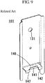
- FIG. 9 illustrates an exemplary conventional fixing device used for installing the siding panel to a wall body W.
- a fixing device 101 illustrated in FIG. 9 which is a metal plate bent to a predetermined shape and fixed to the wall body W via a nail hole 131 with, for example, a screw nail, so as to lock an end portion of a siding board 150.
- two slits are made upward from the bottom edge of the fixing device 101 in a position at about the lower sixth (as shown on the drawing) of in a rectangular-shaped metal plate of the fixing device 101.
- the metal plate between the slits is bent to an approximately right angle, thus a fixing piece 140 is formed. Then, two slits are made into a distal edge portion of this fixing piece 140, trisecting it.
- the siding board 150 includes a lower fixing end 151 and an upper fixing end 152 at the end portions, which are the end portions in the vertical direction on the drawing.
- the lower fixing end 151 is locked with the above-described fixing piece 140 and the center lock piece 141 of the fixing device 101.
- the upper fixing end 152 is locked with the fixing piece 140 and right and left lock pieces 142 and 142.
- the upper fixing end 152 at the lower siding board 150 and the lower fixing end 151 at the upper siding board 150 are butted against each other via the fixing piece 140. Accordingly, the upper and the lower siding boards 150 and 150 can be fixed simultaneously.
- Patent Document 1 Japanese Unexamined Patent Application Publication No. 2006-104742 .
- Patent Document 2 FR2684418 , disclosing a clip comprises at least two superimposed tabs cut out of a flat sheet and bent up onto the front faces of two superimposed cladding panels (tiles). All tabs are bent with respect to the base plate of the clip forming an angle of about 90° so that they do not allow for thermal expansion of the boards to be attached.
- Patent document US20060272261 A1 discloses also a further fastening member for exterior panels.
- the upper fixing end 152 of the lower siding board 150 and the lower fixing end 151 of the upper siding board 150 are both locked by being butted against the common fixing piece 140.
- each siding board 150 has no looseness at the positions and immovably fixed.
- the siding board 150 expands as the external temperature rises. This causes a mismatch in dimensions between a space between the fixing pieces 140 of the fixing devices 101 and 101 disposed on the upper and lower sides and the length between the lower fixing end 151 and the upper fixing end 152 of the siding board 150.
- the siding board 150 manufactured by recycled wood obtained using powder of scrap wood from natural wood and waste plastic as a raw material, is used as the siding board 150. Even if the siding board 150 is appropriately installed at the beginning of the construction as illustrated in (A) in FIG. 11 , expansion of the siding board 150 warps the siding boards 150 itself as illustrated in (B) in FIG. 11 and the exterior wall surface of the built part twists, thus causing a poor appearance.
- warping causes a damage, deformation, and drop of interior and exterior materials, which are the siding boards themselves in this case, also resulting in a damage and a drop of the fixing device. Further, the warping causes a damage and a drop of a caulking material applied on a masonry joint between the siding boards 150, resulting in degrade of waterproof performance of the wall surface.
- preliminarily accommodating thermal expansion of the siding board 150 providing a slight clearance at the fixing device 101 between the upper fixing end 152 of the siding board 150 and the fixing piece 140 of the fixing device 101 gives a looseness at the siding boards 150 between the fixing devices 101.
- This causes rattling at the siding boards 150, generating a risk of damage and drop.
- the change in the width of the masonry joint in accordance with the rattling also may cause, for example, a drop of the caulking material.
- the present invention has been made to solve the drawbacks caused by the related art.
- One of its objectives is to provide a fixing device for a panel such as a siding board with comparatively simple configuration that allows construction with the method similar to the method for the conventional fixing device and prevents warping and deformation of the siding board by absorbing a dimensional change due to expansion of the siding board.
- the siding panel as an exterior material is described.
- the present invention is not limited to this. It is obvious that the present invention is applicable to a panel as interior and exterior materials made of various materials, for example, a board material made of the synthetic wood or a board material made of the synthetic wood constructed as an outdoor deck (referred to as a "panel" in this description).
- a fixing device 1 for a panel comprises all the features of claim 1.
- a subject to be fixed may be a panel comprising a siding board 50 made of synthetic wood manufactured by extrusion molding, and the fixing device 1 may be used for fixing both end portions in a direction orthogonal to an extrusion direction of the siding board 50.
- spacers 2, 2 may be formed by bending along other two sides 1c, 1d orthogonal to the two sides 1a, 1b of the metal plates at a predetermined width and in a same direction, and the three (3) pieces of strip plates 41, 42 and 43 may be formed between the spacers 2, 2.
- the spacers 2, 2 may include a sidewall 21 which is orthogonal to the main body portion 3, and a flange 22 projecting outward from the sidewall 21 and being parallel to the main body portion 3.
- a cutout aperture 24 or a through-hole may be disposed in the spacers 2, 2 at each part positioned outside of the main body portion 3 (lower part with respect to the intermediate line C in FIG. 1 ).
- a fixing device 1 for a panel of the present invention obtains the following remarkable effects.
- the three pieces of leaf spring-shaped strip plates 41, 42, and 43 were bent, and fixing pieces 41a, 42a, and 43a and lock pieces 41b, 42b, and 43b were formed at the respective strip plates 41, 42, and 43. Also, an inclined angle ⁇ 1, which was an angle of the center fixing piece 41a with respect to a main body portion 3, and an inclined angle ⁇ 2, which was an angle of the fixing pieces 42a and 43a on both sides, were set to a different angle.
- each fixing piece 41a, 42a, and 43a was elastically deformed to the extent that the inclined angle ⁇ 1 of the center fixing piece 41a and the inclined angle ⁇ 2 of the other fixing pieces 42a and 43a became the same angle, thus absorbing the dimensional change of the siding board 50 due to expansion.
- the fixing devices 1 are utilized for a panel formed of a siding board 50 made of synthetic wood manufactured by extrusion molding, in which the fixing devices 1 are employed for fixing between end portions of the siding boards 50 in a direction orthogonal to the extrusion direction, where dimensions are restricted, even though the subject to be fixed are the siding boards 50 made of synthetic wood, which swell as a consequence of comparatively large dimensional changes due to changes in temperature, dimensional changes in the siding boards 50 due to heat can be sufficiently absorbed. Additionally, warping, deformation, or similar failure of the panel formed of the siding boards were able to be preferably prevented.
- the strength of the fixing device 1 can be enhanced while keeping the above-described function of absorbing the dimensional change in the siding board 50.
- the siding board 50 was able to be installed away from the wall body W, which is the constructed object, by the width of the spacers 2 and 2.
- the clearance between both facilitates discharging the water.
- the inside of the clearance between the siding board 50 and the wall body W is dried, thus preferably preventing, for example, generation of a mold and erosion.
- the strength of the fixing device 1 can be further improved.
- stability of the siding board 50 in installation was able to be improved.
- the cutout aperture 24 or a through-hole is disposed at a part positioned outside of the main body portion 3 of the spacers 2 and 2 (part lower than an intermediate line C shown on FIG. 1 ). This allows the spacer to be easily cut starting from the cutout aperture 24 or the through-hole part in the case where, for example, the dimension of the fixing device needs to be adjusted.
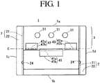
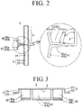
- FIG. 1 to FIG. 3 An exemplary configuration of a fixing device 1 of the present invention is illustrated in FIG. 1 to FIG. 3 .
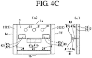
- An exemplary formation procedure of the fixing device is illustrated in FIGS. 4A to 4C .
- the fixing device 1 defines an intermediate line C parallel to two sides 1a and 1b between the two sides 1a and 1b, which are opposed to one another, of a rectangular metal plate.
- a part from the intermediate line C to one side 1a among the two sides 1a and 1b is formed as the main body portion 3 with, for example, a nail hole 31 or similar for installation to the wall body W, which is the constructed object of an architectural structure.
- a plurality of leaf spring-shaped strip plates which are three (3) pieces of strip plates 41 to 43 in the embodiment illustrated in the drawing, are formed orthogonal to the two sides 1a and 1b.
- the above-described intermediate line C is disposed at the approximately intermediate position of the two sides 1a and 1b.
- the intermediate line C may be disposed off-centered toward one of the sides to form the main body portion 3 large or small compared with the embodiment illustrated in the drawing.
- a slit Sh and four (4) slits Sv1 to Sv4, which form a comb-shaped slit as a whole, are formed.
- the slit Sh is parallel to the side 1b.
- the slits Sv1 to Sv4 are orthogonal to the slit Sh and formed between the slit Sh and the intermediate line C. Between the slits Sv1 to Sv4, the three pieces of the strip plates 41, 42, and 43 are formed with the slit Sh at the lower end.
- the shape of the slits is not limited to the embodiment illustrated in the drawing. Various modifications are possible while still achieving the objects of the invention.
- the sides 1c and 1d may be formed as one sides of the right and left strip plates 42 and 43 without disposing the slits Sv1 and Sv4. Further, insofar as the plurality of strip plates are disposed, the number of strip plates disposed at the fixing device 1 may be two pieces or may be equal to or more than four pieces.
- the plurality pieces of strip plates 41, 42, and 43 thus formed are bent to the same direction placing the intermediate line C as fulcrum ((A) in FIG. 4A, (B) in FIG. 4B, (a) in FIG. 4A, and (b) in FIG. 4B ).
- At least one piece among the three pieces of strip plates 41, 42, and 43, which is the center strip plate 41 in the embodiment illustrated in the drawing, and the remaining two pieces of strip plates 42 and 43 are bent to the opposite directions on another at a bend position parallel to and away from the intermediate line C by a predetermined distance (bend line F).
- the fixing pieces 41a, 42a, and 43a are formed at the part from the intermediate line C to the bend line F, and the lock pieces 41b, 42b, and 43b are formed at the part from the bend line F to the distal ends of respective strip plates 41, 42, and 43 ((B) in FIG. 4B , (C) in FIG. 4C, (b) in FIG. 4B and (c) in FIG. 4C ).
- the fixing ends 51b and 52b (described later) of the siding board 50 are locked to the L-shaped lock portions formed by the lock pieces 41b, 42b, and 43b and the fixing pieces 41a, 42a, and 43a.
- the siding boards 50 can be fixed to the wall body W.
- the lock piece 41b disposed at the center strip plate 41 is bent downward to lock the upper fixing end 52b of the lower siding board 50 with the center strip plate 41.
- the lock pieces 42b and 43b disposed at the right and left strip plates 42 and 43 are bent upward to lock the lower fixing end 51b of the upper siding board 50 with the right and left strip plates 42 and 43.
- the lock pieces 42b and 43b of the right and left strip plates 42 and 43 may be bent downward to lock the upper fixing end 52b of the lower siding board 50.
- the lock piece 41b of the center strip plate 41 may be bent upward to lock the lower fixing end 51b of the upper lower siding board 50.
- the fixing piece 41a which is disposed at the center strip plate 41, and the fixing pieces 42a and 43a, which are disposed at the right and left strip plates 42 and 43, are bent at the respective different inclined angles ⁇ 1 and ⁇ 2 (see the enlarged view in FIG. 2 ) with respect to the above-described main body portion 3.
- the inclined angle ⁇ 1 of the fixing piece 41a disposed at the center strip plate 41 is formed to slightly obtuse angle (approximately 93°) while the inclined angle ⁇ 2 of the fixing pieces 42a and 43a disposed at the right and left strip plates 42 and 43 are formed to slightly acute angle (approximately 87°).
- the center fixing piece 41a and the right and left fixing pieces 42a and 43a are formed to provide a predetermined angle difference (approximately 6 degrees in the embodiment illustrated in the drawing) between them.
- a predetermined angle difference approximately 6 degrees in the embodiment illustrated in the drawing.
- the inclined angle ⁇ 1 of the center fixing piece 41a and the inclined angle ⁇ 2 of the right and left fixing pieces 42a and 43a can be appropriately adjusted according to the amount of change in dimensions of the siding board 50.
- the difference between the inclined angle ⁇ 1 of the center fixing piece 41a and the inclined angle ⁇ 2 of the right and left fixing pieces 42a and 43a may be provided larger.
- the angle difference may be provided small.
- the inclined angle ⁇ 1 of the center fixing piece 41a is configured to be an obtuse angle with respect to the main body portion 3 while the inclined angle ⁇ 2 of the right and left fixing pieces 42a and 43a is configured to be an acute angle with respect to the main body portion 3.
- the lock end portion disposed on the upper end side of the lower siding board is fixed by being butted against the center fixing piece 41a.
- the lock end portions disposed on the lower end side of the upper siding board is fixed by being butted against the right and left fixing pieces 42a and 43a.
- the inclined angle ⁇ 1 of the center fixing piece 41a may be configured to be an acute angle with respect to the main body portion 3 while the inclined angle ⁇ 2 of the right and left fixing pieces 42a and 43a may be configured to be an obtuse angle with respect to the main body portion 3.
- the lock end portions disposed on the upper end of the lower siding board may be fixed by being butted against the right and left fixing pieces 42a and 43a.
- the lock end portion disposed on the lower end of the upper siding board is fixed by being butted against the center fixing piece 41a.
- each lock piece 41b, 42b, and 43b may be as it is.
- the lock pieces 41b, 42b, and 43b may be bent in the upside-down direction with respect to the example illustrated in the drawing.
- the spacers 2 and 2 may be formed as the parts bent from the two sides 1c and 1d by the predetermined width in the same direction as illustrated in FIG. 1 to FIG. 3 .
- the spacers 2 and 2 may restrict the space between the wall body W and the back surface of the siding board.
- parts near the two sides 1c and 1d in the height direction of the fixing device 1 are bent to L shape to form the spacers 2 and 2.
- the spacers 2 and 2 are formed of the sidewalls 21 and 21, which project forward at the predetermined length, and the flanges 22 and 22, which project outward from the sidewalls 21 and 21.
- the above-described three-piece strip plates 41 to 43 are formed between the two spacers 2 and 2.
- the spacers 2 and 2 thus disposed allow substantially improves the bending strength of the fixing device 1 orthogonal to the two sides 1c and 1d.
- Installing the siding boards 50 to the wall body W using the fixing devices 1 allows providing a space (5 mm in this embodiment) corresponding to the projection length of the spacers 2 and 2 between the wall body W and the back surface of the siding board 50.
- a space 5 mm in this embodiment
- the entered rain water is quickly discharged via the space.
- Air passing through the space dries the inside of the space, a problem caused by filling of water vapor or humidity being filled, for example, generation of a mold or similar problem can be preferably prevented.
- reference numeral 24 denotes a cutout aperture disposed at the above-described spacers 2 and 2.
- a through-hole is preliminary disposed at the part that becomes a boundary between the sidewall 21 and the flange 22 of metal plate.
- the metal plate is bent at the boundary part to form the spacer 2, thus forming semi arc-shaped cutout apertures at both the flange 22 and the sidewall 21.
- the fixing devices 1 of the present invention are used for fixing the lower fixing end 51b of the lowest siding board 50, disposing the cutout apertures 24 allows easily cutting the spacers 2 and 2 at the cutout aperture 24 positions with, for example, a tin snip, a metal saw, or similar tool.
- the spacers 2 and 2 can be easily cut by grabbing and bending the part near the formation position of the cutout aperture 24 with, for example, pliers. Accordingly, the size of the fixing device 1 can be easily adjusted in field work.
- the cutout apertures 24 are disposed at the parts where the spacers 2 and 2 can be cut.
- the parts are not limited for the cutout apertures 24.
- the through-holes for example, may be formed at the parts.
- the plurality of cutout apertures 24 or through-holes may be disposed lower side of the intermediate line C in the height direction of the spacers 2 and 2, for example, with spaces equally provided.
- the dimensions of the fixing device 1 can also be finely adjusted by cutting the spacers 2 and 2 at any one of formation positions of the cutout apertures or the through-holes.
- the fixing device 1 of the present invention thus configured is formed using an exemplary metal plate with a thickness of 1 mm.
- the fixing device 1 has a width of 60 mm, a height of 43 mm, a thickness of 5 mm at the spacer 2.
- the siding boards 50 fixed with the fixing devices 1 include the fixing ends 51b and 52b on both end sides in the width direction (vertical direction) as illustrated in FIG. 8 .
- the fixing ends 51b and 52b are locked to the strip plate 41, 42, or 43 disposed at the above-described fixing device 1.
- the upper fixing end 52b and the lower fixing end 51b are configured to cover an upper end portion 52 of the lower siding board 50 with a lower end portion 51 of the upper siding board 50. Accordingly, rain water or similar object flowing along the outer surface of the siding board 50 is prevented from entering the inside via a coupling portion of the siding boards 50.
- the cross-sectional shape of the lower end portion 51 of the siding board 50 in the thickness direction is formed in the shape of a roughly downward-pointing square C shape.
- An outer surface side leg 51a formed at the C shape part is formed longer than an inner surface side leg 51b.
- the inner surface side leg 51b is formed as the lower fixing end 51b to be locked to the above-described lock pieces 42b and 43b disposed at the fixing device 1.
- the cross-sectional shape of the upper end portion 52 of the siding board 50 in the thickness direction is notched on the outer surface side and formed to a tenon shape thinned by the amount of thickness of the outer surface side leg 51a of the lower end portion 51.
- the tenon part can be inserted into the space between the outer surface side leg 51a, which is disposed at the lower end portion 51 of the upper siding board 50 as illustrated in FIG. 6 , and the fixing device 1.
- a groove 52a is disposed at the tenon-shaped upper end portion 52 at the center in the thickness direction.
- the lock piece 41b of the center strip plate 41, which is disposed at the fixing device 1, can be inserted in the groove 52a. Accordingly, the part forming the inner surface side with respect to the groove 52a is configured as the upper fixing end 52b fixed with the fixing device 1.
- the upper and lower ends of the siding board 50 are not limited to the shape illustrated in FIG. 5 to FIGS. 7A to 7C .
- the upper and lower ends of the siding board 50 may have the same shape as the upper and lower ends of the known siding board 150 described with reference to FIG. 10 as an example having common basic shape.
- reference numeral 54 denotes a hollow space continuously formed in the extrusion direction of the siding board 50 formed by extrusion molding in this embodiment. Forming the hollow space 54 achieves weight reduction of the siding board 50 and reduction of amount of raw material used per board, bringing cost reduction.
- the exemplary siding boards 50 used in the embodiment each have a length of 2000 mm, a total width of 166 mm, a distance between the fixing ends 51b and 52b is 147 mm, and a thickness of 21.25 mm.
- the siding board 50 is installed to the wall body W by being fixed with the fixing devices 1 at both ends in the width direction.
- the fixing device 1 is fixed to the wall body W with, for example, screw nail such that the right and left fixing pieces 42a and 43a of the fixing device 1 are arranged at the installation position of the lower fixing end 51b of the lowest siding board 50.
- the lower end portion of the fixing device 1 may be cut at the formation position of the cutout apertures 24 disposed at the spacers 2 and 2.
- the fixing device 1 is covered with the outer surface side leg 51a disposed at the lower end portion 51 of the siding board 50 when the lower fixing end 51b of the siding board 50 is fixed to the fixing device 1 as illustrated in FIG. 5 .
- the fixing devices 1 are installed to the wall body W providing equal space of 450 mm laterally.
- the installation space can be appropriately changed according to, for example, the scale of the architectural structure to be constructed and the weight of the used siding board 50, though.
- the lower fixing end 51b of the lowest siding board 50 is locked to the strip plates 42 and 43 disposed at the fixing device 1 and the siding board 50 is disposed parallel to the wall body W. Then, the upper fixing end 52b of the siding board 50 is locked to the center strip plate 41 disposed at the fixing device 1, and the fixing device 1 is fixed to the wall body W in this state with, for example, a screw nail.
- the fixing device 1 was installed with a space of 450 mm similarly to the above-described lowest fixing device 1.
- the space is variable according to, for example, the weight of the siding board 50 to be installed and the scale of the architectural structure.
- fixing the upper fixing ends 52b of the siding boards 50 with the fixing devices 1 allows fixing both of the upper and lower ends of the siding boards 50 with the fixing devices 1 and installing the siding boards 50 on the wall body W.
- the right and left strip plates 42 and 43 which are disposed at the fixing device 1 that fixes the upper fixing end 52b of the siding board 50, can further lock the lower fixing end 51b of another siding board 50. Placing the lower fixing end 51b of the second-stage siding board 50 to the right and left strip plates 42 and 43 disposed at the second-stage fixing device 1 allows stacking another (second stage) siding board 50 on the first-stage siding board 50.
- the upper end portion 52 of the second-stage siding board 50 is fixed with another fixing device 1. Repeating this work allows installing the siding boards 50 to the wall body W up to required height.
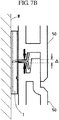
- the siding boards 50 which are installed to the wall body W using the fixing devices 1 of the present invention, are similar to the configuration of the related art described with reference to FIG. 10 in that the upper fixing end 52b of the lower siding board 50 and the lower fixing end 51b of the upper siding board 50 are vertically disposed via the fixing pieces 41a, 42a, and 43a disposed at the strip plates 41 to 43 as illustrated in FIG. 6 and FIGS. 7A to 7C .
- both the upper fixing end 152 of the lower siding board 150 and the lower fixing end 151 of the upper siding board 150 have the conventional configuration (see FIG. 10 ) where both are butted against the single fixing piece 140.
- the fixing device 1 of the present invention fixes the position of the siding boards 50 by butting the upper fixing end 52b of the lower siding board 50 to the fixing piece 41a disposed at the center strip plate 41, and the lower fixing end 51b of the upper siding board 50 to the fixing pieces 42a and 43a disposed at the right and left strip plates 42 and 43.
- the inclined angle ⁇ 1 of the center fixing piece 41a with respect to the main body portion 3 and the inclined angle ⁇ 2 of the right and left fixing pieces 42a and 43a are formed to be mutually different angle.
- a space equal to or more than the thickness (1 mm)of the metal plate constituting the fixing device 1 (2 mm in the embodiment illustrated in the drawing) is formed.
- the above-described dimensional absorption range is set to 1 mm.
- the absorption range of equal to or more than 1 mm may be provided by, for example, further increasing the difference between the inclined angle ⁇ 1 of the center fixing piece 41a and the inclined angle ⁇ 2 of the right and left fixing pieces 42a and 43a.
- the absorption range may be set small by, for example, reducing the difference between the inclined angles ⁇ 1 and ⁇ 2.
- the dimensional change is approximately 0.6% at maximum.
- the absorption range of the dimensions is provided approximately 0.7% (approximately 1 mm in the embodiment illustrated in the drawing where the distance between the fixing ends is 147 mm) with respect to the distance between the upper and lower fixing ends of each siding board to be fixed.
- This preferably absorbs the dimensional change in the siding board made of synthetic wood.
Landscapes
- Engineering & Computer Science (AREA)
- Architecture (AREA)
- General Engineering & Computer Science (AREA)
- Civil Engineering (AREA)
- Structural Engineering (AREA)
- Mechanical Engineering (AREA)
- Chemical & Material Sciences (AREA)
- Ceramic Engineering (AREA)
- Finishing Walls (AREA)
Claims (5)
- Eine Befestigungsvorrichtung (1) für eine Platte, umfassend:eine rechteckförmige Metalplatte mit zwei gegenüberliegend angeordneten Seiten (1a, 1b),eine zwischenliegende Linie (C), die derart definiert ist, dass sie zwischen den zwei Seiten (1a, 1b) und parallel zu den zwei Seiten (1a, 1b) verläuft und,einen Hauptkörperabschnitt (3), der von einer sich von der zwischenliegenden Linie (C) zu einer Seite (1a) der beiden Seiten (1a, 1b) erstreckenden Fläche gebildet ist,einen Schlitz, der innerhalb einer sich von der zwischenliegenden Linie (C) zu der anderen Seite (1b) der beiden Seiten (1a, 1b) erstreckenden Fläche ausgebildet ist,eine Vielzahl von blattfederförmig ausgebildeten, streifenartigen Platten (41, 42 und 43), die sich durchgehend an den Hauptkörperabschnitt (3) entlang der zwischenliegenden Linie (C) anschließen, undein in dem Hauptkörperabschnitt (3) angeordnetes Nagelloch (31), das zur Befestigung an einem Wandkörper (W) vorgesehen ist, wobei die Vielzahl von blattfederförmig ausgebildeten, streifenartigen Platten (41, 42 und 43) derart ausgebildet ist, dass sie orthogonal zu den zwei Seiten (1a, 1b) geformt und anschließend im Bereich der zwischenliegenden Linie (C) in den entlang des Hauptkörperabschnitt (3) verlaufenden Richtungen gebogen sind,zumindest eine der Vielzahl von streifenartigen Platten (41, 42 und 43) in einer vorgegeben Richtung um eine Biegelinie gebogen ist, die sich parallel zu der zwischenliegenden Linie (C) und in einem vorgegebenen Abstand von derselben erstreckt,die übrigen streifenartigen Platten (42, 43) in einer der obigen vorgegebenen Richtung entgegengesetzten Richtung derart gebogen sind, dass sich ihre Biegelinien ebenfalls parallel zu der zwischenliegenden Linie (C) und in einem vorgegebenen Abstand von derselben erstrecken, unddie Oberfläche jeder der streifenartigen Platten (41, 42 und 43), die sich zwischen der zwischenliegenden Linie (C) und der entsprechenden Biegelinie erstreckt, einen Befestigungsabschnitt (41a, 42a und 43a) bildet, wohingegen die Oberfläche der jeweiligen Platte, die sich zwischen der entsprechenden Biegelinie und dem jeweiligen abgewandten Ende erstreckt, einen Verriegelungsabschnitt (41b, 42b und 43b) bildet,dadurch gekennzeichnet, dassein auf den Hauptkörperabschnitt (3) bezogene Neigungswinkel (θ1) des Befestigungsabschnitts (41a), der als Bestandteil der wenigstens einer streifenartigen Platte (41) von der Vielzahl von streifenartigen Platten (41, 42, 43) ausgebildet ist, an der der entsprechende Verriegelungsabschnitt (41b) in die vorgegebenen Richtung ausgebogenen ist, derart eingestellt ist, dass er verschieden von dem auf den Hauptkörperabschnitt (3) bezogenen Neigungswinkel (02) der Befestigungsabschnitte (42a, 43a) ist, die als Bestandteile der besagten übrigen streifenartigen Platten (42, 43) ausgebildet sind,und nachdem die Platte gespreizt worden ist, unterliegt jede der streifenartigen Platten (41, 42 und 43) einer elastischen Verformung, die in einem Ausmaß erfolgt, das bewirkt, dass der Neigungswinkel (θ1) des Befestigungsabschnitts (41a), der als Bestandteil der wenigstens einer streifenartigen Platte (41) der Vielzahl von streifenartigen Platten (41, 42, 43), an der sich der entsprechende, in die vorgegebenen Richtung ausgebogene Verriegelungsabschnitt (41b) anschließt, und der Neigungswinkel (02) der Befestigungsabschnitte (42a, 43a) ist, die als Bestandteile der besagten übrigen streifenartigen Platten (42, 43) ausgebildet sind, zu einem gleich großen Winkel werden.
- Die Befestigungsvorrichtung (1) für eine Platte nach Anspruch 1, dadurch gekennzeichnet, dass die Befestigungsvorrichtung zur Befestigung von
einer Verkleidungsplatte (50), die aus Kunstholz in einem Strangpressverfahren hergestellt ist, insbesondere zur Befestigung der beiden Endabschnitte derartiger Verkleidungsplatte (50) in einer senkrecht zur Richtung des Strangpressvorgangs verlaufenden Richtung, vorgesehen ist. - Die Befestigungsvorrichtung (1) für eine Platte nach Anspruch 1 oder 2, dadurch gekennzeichnet, dass die Vielzahl von streifenartigen Platten als drei streifenartige Platten ausgebildet ist und dass zwei Abstandhalter (2, 2) vorgesehen sind, die durch Biegen entlang der zwei Seiten (1c, 1d), die sich senkrecht zu den zwei parallel zu der zwischenliegenden Linie (C) angeordneten Seiten (1a, 1b) der Metallplatte erstrecken, ausgebildet sind, wobei das Biegen in einem vorgegebenen Breitenbereich und in derselben Richtung erfolgt und die drei streifenartigen Platten (41, 42 und 43) zwischen den Abstandhaltern (2) angeordnet sind.
- Die Befestigungsvorrichtung (1) für eine Platte nach Anspruch 3, dadurch gekennzeichnet, dass die Abstandhalter (2) jeweils eine Seitenwand (21) und einen Flansch (22) umfassen, wobei die Seitenwand (21) senkrecht zu dem Hauptkörperabschnitt (3) angeordnet ist und der Flansch (22) von der jeweiligen Seitenwand (21) in Auswärtsrichtung absteht und dabei sich parallel zu dem Hauptkörperabschnitt (3) erstreckt.
- Die Befestigungsvorrichtung (1) für eine Platte nach Anspruch 3 oder 4, dadurch gekennzeichnet, dass in jedem der Abstandhalter (2, 2) eine Aussparung (24) bzw. eine Durchgangsbohrung vorgesehen ist, die außerhalb des Hauptkörperabschnittes (3) angeordnet ist.
Applications Claiming Priority (2)
| Application Number | Priority Date | Filing Date | Title |
|---|---|---|---|
| JP2011147280A JP5358624B2 (ja) | 2011-07-01 | 2011-07-01 | パネル用の固定金具 |
| PCT/JP2012/066590 WO2013005648A1 (ja) | 2011-07-01 | 2012-06-28 | パネル用の固定金具 |
Publications (3)
| Publication Number | Publication Date |
|---|---|
| EP2728087A1 EP2728087A1 (de) | 2014-05-07 |
| EP2728087A4 EP2728087A4 (de) | 2015-04-08 |
| EP2728087B1 true EP2728087B1 (de) | 2018-05-09 |
Family
ID=47437003
Family Applications (1)
| Application Number | Title | Priority Date | Filing Date |
|---|---|---|---|
| EP12807010.9A Not-in-force EP2728087B1 (de) | 2011-07-01 | 2012-06-28 | Befestigungsteile für eine tafel |
Country Status (5)
| Country | Link |
|---|---|
| US (1) | US9410566B2 (de) |
| EP (1) | EP2728087B1 (de) |
| JP (1) | JP5358624B2 (de) |
| CN (1) | CN103620133B (de) |
| WO (1) | WO2013005648A1 (de) |
Families Citing this family (15)
| Publication number | Priority date | Publication date | Assignee | Title |
|---|---|---|---|---|
| US9267295B2 (en) * | 2010-07-09 | 2016-02-23 | Matthew Mann | Suspension rails for panel veneer systems |
| JP6490410B2 (ja) * | 2014-11-28 | 2019-03-27 | ケイミュー株式会社 | 外装材の施工構造 |
| EP2927391A1 (de) * | 2014-04-04 | 2015-10-07 | Gaber S.R.L. | Vorrichtung zur befestigung funktionaler und dekorativer elemente wie gemälde, paneele und dergleichen an einer wand und funktionale und dekorative elemente mit der befestigungsvorrichtung |
| EP3347546B1 (de) * | 2015-09-11 | 2020-07-29 | Oldcastle Building Products Canada Inc. | Verkleidungssystem |
| JP1584602S (de) * | 2017-03-27 | 2017-08-28 | ||
| CN108265934B (zh) * | 2017-08-08 | 2024-01-23 | 傅明 | 装饰板组件 |
| JP6931773B2 (ja) * | 2017-11-28 | 2021-09-08 | パナソニックIpマネジメント株式会社 | 食器洗い機 |
| WO2020061034A1 (en) * | 2018-09-19 | 2020-03-26 | Fiber Composites, LLC (dba Fiberon) | Siding clip |
| USD962048S1 (en) | 2019-04-30 | 2022-08-30 | Hunter Douglas Inc. | Coupling device for mounting tiles to a building |
| US11905713B2 (en) | 2019-04-30 | 2024-02-20 | Hunter Douglas Inc. | Coupling system for mounting tiles to a building |
| US11459768B2 (en) * | 2019-10-31 | 2022-10-04 | Certainteed Llc | Attachment clip for building surface panels and building surface panel system |
| JP1679083S (de) | 2020-07-22 | 2021-02-15 | ||
| JP1679082S (de) | 2020-07-22 | 2021-02-15 | ||
| WO2022130502A1 (ja) * | 2020-12-15 | 2022-06-23 | 積水ハウス株式会社 | 外壁材取付部材、下端部外壁材取付部材、及び外壁材取付構造 |
| US20240254777A1 (en) * | 2023-01-30 | 2024-08-01 | Haoheng (Fujian) Building Materials Technology Co., Ltd. | Ceramic tile hanging system |
Family Cites Families (13)
| Publication number | Priority date | Publication date | Assignee | Title |
|---|---|---|---|---|
| JPS6126806U (ja) * | 1984-07-25 | 1986-02-18 | 松下電工株式会社 | 外装材取付金具 |
| JP2711719B2 (ja) | 1989-06-12 | 1998-02-10 | 戸田工業株式会社 | 磁気記録用針状晶鉄合金磁性粒子粉末 |
| JPH0542468U (ja) * | 1991-05-29 | 1993-06-08 | 松下電工株式会社 | スタツド |
| JP2889974B2 (ja) | 1991-08-12 | 1999-05-10 | 三ツ星ベルト株式会社 | Vリブドベルトの製造方法および同製造方法に用いるグラインダーホイール |
| FR2684418B1 (fr) | 1991-11-28 | 1994-01-21 | Philippe Apeloig | Agrafe pour la fixation de plaques de revetement sur un mur. |
| JP2004211526A (ja) * | 2002-11-14 | 2004-07-29 | Misawa Homes Co Ltd | 化粧壁構造および支持部材 |
| JP2005220577A (ja) * | 2004-02-04 | 2005-08-18 | Sekisui House Ltd | 外壁固定具 |
| JP2006104742A (ja) | 2004-10-04 | 2006-04-20 | Kenji Omiya | 外断熱建物のサイディング外壁構造及びこれに用いるサイディング支持用ブラケット |
| JP4546301B2 (ja) * | 2005-03-22 | 2010-09-15 | ニチハ株式会社 | 留め付け金具及び外壁施工構造 |
| DE202005005425U1 (de) * | 2005-04-05 | 2005-06-16 | Karl Pedross Ag | Vorrichtung zum Befestigen von Abschlußleisten |
| CN100543252C (zh) * | 2006-07-17 | 2009-09-23 | 季资元 | 一种易装地板及其铺设方法 |
| RU2503787C1 (ru) * | 2009-09-30 | 2014-01-10 | Кей Эм Ю Ко., Лтд. | Зажим для материала для наружной отделки и зажимная конструкция для материала для наружной отделки |
| PL2447440T3 (pl) * | 2010-11-02 | 2015-05-29 | Rockwool Int | Wspornik mocujący, układ zawierający taki wspornik mocujący i zastosowanie wspornika mocującego |
-
2011
- 2011-07-01 JP JP2011147280A patent/JP5358624B2/ja not_active Expired - Fee Related
-
2012
- 2012-06-28 US US14/130,088 patent/US9410566B2/en not_active Expired - Fee Related
- 2012-06-28 EP EP12807010.9A patent/EP2728087B1/de not_active Not-in-force
- 2012-06-28 WO PCT/JP2012/066590 patent/WO2013005648A1/ja not_active Ceased
- 2012-06-28 CN CN201280031123.0A patent/CN103620133B/zh not_active Expired - Fee Related
Non-Patent Citations (1)
| Title |
|---|
| None * |
Also Published As
| Publication number | Publication date |
|---|---|
| HK1190440A1 (zh) | 2014-07-04 |
| EP2728087A1 (de) | 2014-05-07 |
| WO2013005648A1 (ja) | 2013-01-10 |
| JP2013014903A (ja) | 2013-01-24 |
| CN103620133B (zh) | 2016-06-01 |
| US20140199117A1 (en) | 2014-07-17 |
| CN103620133A (zh) | 2014-03-05 |
| US9410566B2 (en) | 2016-08-09 |
| EP2728087A4 (de) | 2015-04-08 |
| JP5358624B2 (ja) | 2013-12-04 |
Similar Documents
| Publication | Publication Date | Title |
|---|---|---|
| US9410566B2 (en) | Fixing device for panel | |
| US20200071934A1 (en) | Wall structure for building, attachment apparatus, and board material construction method | |
| EP2615219B1 (de) | Kit aus Teilen zum Montieren einer Fensterauskleidung und Verfahren zur Bereitstellung einer Fensterauskleidung unter Verwendung des Teilekits | |
| KR20140056158A (ko) | 범용 파티션용 가변형 가이드 | |
| KR20140008144A (ko) | 조립식 주택용 패널을 이용한 조립식 주택의 조립구조물 및 이를 포함하는 조립식 주택 | |
| US8176710B2 (en) | Frame member extender and method for forming the same | |
| CN205766740U (zh) | 固定撑件、模板支撑固定装置及模具 | |
| CN113646493B (zh) | 建筑壁骨、包括它的墙壁结构和设置墙壁结构的方法 | |
| US20070271869A1 (en) | Corner framing member | |
| JP3877221B2 (ja) | 入隅部用内壁パネル固定金具及び入隅部における内壁パネルの固定構造 | |
| HK1190440B (en) | Affixing hardware for panel | |
| KR101612796B1 (ko) | 커튼월 및 그 제작방법 | |
| KR101516008B1 (ko) | 사이즈 가변 문짝 | |
| KR101040234B1 (ko) | 데크 어셈블리 | |
| CN207974437U (zh) | 阴角收边条以及阴角收边结构 | |
| US20190016003A1 (en) | Toold for cutting panels, in particular made of reconstituted material | |
| KR200198978Y1 (ko) | 콘크리트구조물의 접이식 거푸집장치 | |
| JP6678465B2 (ja) | 内窓枠構造用枠材及び内窓枠構造 | |
| JP3849983B2 (ja) | 内壁パネル固定金具及び内壁パネルの固定構造 | |
| CN220522986U (zh) | 蜂窝板模组及蜂窝板 | |
| US3425181A (en) | Paneling arrangement | |
| KR100803224B1 (ko) | 스틸 스터드 패널 제조용 작업대 | |
| CN204139494U (zh) | 一种木塑材料易拼接板 | |
| FI123601B (fi) | Seinärakenne ja menetelmä seinärakenteen valmistamiseksi | |
| KR200298613Y1 (ko) | 목조 판넬의 조립구조 |
Legal Events
| Date | Code | Title | Description |
|---|---|---|---|
| PUAI | Public reference made under article 153(3) epc to a published international application that has entered the european phase |
Free format text: ORIGINAL CODE: 0009012 |
|
| 17P | Request for examination filed |
Effective date: 20131217 |
|
| AK | Designated contracting states |
Kind code of ref document: A1 Designated state(s): AL AT BE BG CH CY CZ DE DK EE ES FI FR GB GR HR HU IE IS IT LI LT LU LV MC MK MT NL NO PL PT RO RS SE SI SK SM TR |
|
| DAX | Request for extension of the european patent (deleted) | ||
| RA4 | Supplementary search report drawn up and despatched (corrected) |
Effective date: 20150305 |
|
| RIC1 | Information provided on ipc code assigned before grant |
Ipc: E04F 13/08 20060101ALI20150227BHEP Ipc: E04F 13/21 20060101ALI20150227BHEP Ipc: E04F 13/26 20060101AFI20150227BHEP Ipc: F16B 5/00 20060101ALI20150227BHEP |
|
| 17Q | First examination report despatched |
Effective date: 20160607 |
|
| GRAP | Despatch of communication of intention to grant a patent |
Free format text: ORIGINAL CODE: EPIDOSNIGR1 |
|
| INTG | Intention to grant announced |
Effective date: 20171013 |
|
| GRAS | Grant fee paid |
Free format text: ORIGINAL CODE: EPIDOSNIGR3 |
|
| GRAJ | Information related to disapproval of communication of intention to grant by the applicant or resumption of examination proceedings by the epo deleted |
Free format text: ORIGINAL CODE: EPIDOSDIGR1 |
|
| GRAL | Information related to payment of fee for publishing/printing deleted |
Free format text: ORIGINAL CODE: EPIDOSDIGR3 |
|
| GRAR | Information related to intention to grant a patent recorded |
Free format text: ORIGINAL CODE: EPIDOSNIGR71 |
|
| INTC | Intention to grant announced (deleted) | ||
| GRAA | (expected) grant |
Free format text: ORIGINAL CODE: 0009210 |
|
| AK | Designated contracting states |
Kind code of ref document: B1 Designated state(s): AL AT BE BG CH CY CZ DE DK EE ES FI FR GB GR HR HU IE IS IT LI LT LU LV MC MK MT NL NO PL PT RO RS SE SI SK SM TR |
|
| INTG | Intention to grant announced |
Effective date: 20180403 |
|
| REG | Reference to a national code |
Ref country code: GB Ref legal event code: FG4D |
|
| REG | Reference to a national code |
Ref country code: CH Ref legal event code: EP Ref country code: AT Ref legal event code: REF Ref document number: 997690 Country of ref document: AT Kind code of ref document: T Effective date: 20180515 |
|
| REG | Reference to a national code |
Ref country code: DE Ref legal event code: R096 Ref document number: 602012046225 Country of ref document: DE Ref country code: IE Ref legal event code: FG4D |
|
| REG | Reference to a national code |
Ref country code: NL Ref legal event code: MP Effective date: 20180509 |
|
| REG | Reference to a national code |
Ref country code: LT Ref legal event code: MG4D |
|
| PG25 | Lapsed in a contracting state [announced via postgrant information from national office to epo] |
Ref country code: BG Free format text: LAPSE BECAUSE OF FAILURE TO SUBMIT A TRANSLATION OF THE DESCRIPTION OR TO PAY THE FEE WITHIN THE PRESCRIBED TIME-LIMIT Effective date: 20180809 Ref country code: NO Free format text: LAPSE BECAUSE OF FAILURE TO SUBMIT A TRANSLATION OF THE DESCRIPTION OR TO PAY THE FEE WITHIN THE PRESCRIBED TIME-LIMIT Effective date: 20180809 Ref country code: FI Free format text: LAPSE BECAUSE OF FAILURE TO SUBMIT A TRANSLATION OF THE DESCRIPTION OR TO PAY THE FEE WITHIN THE PRESCRIBED TIME-LIMIT Effective date: 20180509 Ref country code: ES Free format text: LAPSE BECAUSE OF FAILURE TO SUBMIT A TRANSLATION OF THE DESCRIPTION OR TO PAY THE FEE WITHIN THE PRESCRIBED TIME-LIMIT Effective date: 20180509 Ref country code: SE Free format text: LAPSE BECAUSE OF FAILURE TO SUBMIT A TRANSLATION OF THE DESCRIPTION OR TO PAY THE FEE WITHIN THE PRESCRIBED TIME-LIMIT Effective date: 20180509 Ref country code: LT Free format text: LAPSE BECAUSE OF FAILURE TO SUBMIT A TRANSLATION OF THE DESCRIPTION OR TO PAY THE FEE WITHIN THE PRESCRIBED TIME-LIMIT Effective date: 20180509 |
|
| PG25 | Lapsed in a contracting state [announced via postgrant information from national office to epo] |
Ref country code: LV Free format text: LAPSE BECAUSE OF FAILURE TO SUBMIT A TRANSLATION OF THE DESCRIPTION OR TO PAY THE FEE WITHIN THE PRESCRIBED TIME-LIMIT Effective date: 20180509 Ref country code: NL Free format text: LAPSE BECAUSE OF FAILURE TO SUBMIT A TRANSLATION OF THE DESCRIPTION OR TO PAY THE FEE WITHIN THE PRESCRIBED TIME-LIMIT Effective date: 20180509 Ref country code: HR Free format text: LAPSE BECAUSE OF FAILURE TO SUBMIT A TRANSLATION OF THE DESCRIPTION OR TO PAY THE FEE WITHIN THE PRESCRIBED TIME-LIMIT Effective date: 20180509 Ref country code: RS Free format text: LAPSE BECAUSE OF FAILURE TO SUBMIT A TRANSLATION OF THE DESCRIPTION OR TO PAY THE FEE WITHIN THE PRESCRIBED TIME-LIMIT Effective date: 20180509 Ref country code: GR Free format text: LAPSE BECAUSE OF FAILURE TO SUBMIT A TRANSLATION OF THE DESCRIPTION OR TO PAY THE FEE WITHIN THE PRESCRIBED TIME-LIMIT Effective date: 20180810 |
|
| REG | Reference to a national code |
Ref country code: AT Ref legal event code: MK05 Ref document number: 997690 Country of ref document: AT Kind code of ref document: T Effective date: 20180509 |
|
| REG | Reference to a national code |
Ref country code: DE Ref legal event code: R119 Ref document number: 602012046225 Country of ref document: DE |
|
| PG25 | Lapsed in a contracting state [announced via postgrant information from national office to epo] |
Ref country code: EE Free format text: LAPSE BECAUSE OF FAILURE TO SUBMIT A TRANSLATION OF THE DESCRIPTION OR TO PAY THE FEE WITHIN THE PRESCRIBED TIME-LIMIT Effective date: 20180509 Ref country code: PL Free format text: LAPSE BECAUSE OF FAILURE TO SUBMIT A TRANSLATION OF THE DESCRIPTION OR TO PAY THE FEE WITHIN THE PRESCRIBED TIME-LIMIT Effective date: 20180509 Ref country code: AT Free format text: LAPSE BECAUSE OF FAILURE TO SUBMIT A TRANSLATION OF THE DESCRIPTION OR TO PAY THE FEE WITHIN THE PRESCRIBED TIME-LIMIT Effective date: 20180509 Ref country code: RO Free format text: LAPSE BECAUSE OF FAILURE TO SUBMIT A TRANSLATION OF THE DESCRIPTION OR TO PAY THE FEE WITHIN THE PRESCRIBED TIME-LIMIT Effective date: 20180509 Ref country code: CZ Free format text: LAPSE BECAUSE OF FAILURE TO SUBMIT A TRANSLATION OF THE DESCRIPTION OR TO PAY THE FEE WITHIN THE PRESCRIBED TIME-LIMIT Effective date: 20180509 Ref country code: SK Free format text: LAPSE BECAUSE OF FAILURE TO SUBMIT A TRANSLATION OF THE DESCRIPTION OR TO PAY THE FEE WITHIN THE PRESCRIBED TIME-LIMIT Effective date: 20180509 Ref country code: DK Free format text: LAPSE BECAUSE OF FAILURE TO SUBMIT A TRANSLATION OF THE DESCRIPTION OR TO PAY THE FEE WITHIN THE PRESCRIBED TIME-LIMIT Effective date: 20180509 |
|
| REG | Reference to a national code |
Ref country code: CH Ref legal event code: PL |
|
| PG25 | Lapsed in a contracting state [announced via postgrant information from national office to epo] |
Ref country code: SM Free format text: LAPSE BECAUSE OF FAILURE TO SUBMIT A TRANSLATION OF THE DESCRIPTION OR TO PAY THE FEE WITHIN THE PRESCRIBED TIME-LIMIT Effective date: 20180509 Ref country code: IT Free format text: LAPSE BECAUSE OF FAILURE TO SUBMIT A TRANSLATION OF THE DESCRIPTION OR TO PAY THE FEE WITHIN THE PRESCRIBED TIME-LIMIT Effective date: 20180509 |
|
| REG | Reference to a national code |
Ref country code: BE Ref legal event code: MM Effective date: 20180630 |
|
| PLBE | No opposition filed within time limit |
Free format text: ORIGINAL CODE: 0009261 |
|
| STAA | Information on the status of an ep patent application or granted ep patent |
Free format text: STATUS: NO OPPOSITION FILED WITHIN TIME LIMIT |
|
| PG25 | Lapsed in a contracting state [announced via postgrant information from national office to epo] |
Ref country code: MC Free format text: LAPSE BECAUSE OF FAILURE TO SUBMIT A TRANSLATION OF THE DESCRIPTION OR TO PAY THE FEE WITHIN THE PRESCRIBED TIME-LIMIT Effective date: 20180509 Ref country code: LU Free format text: LAPSE BECAUSE OF NON-PAYMENT OF DUE FEES Effective date: 20180628 |
|
| REG | Reference to a national code |
Ref country code: IE Ref legal event code: MM4A |
|
| 26N | No opposition filed |
Effective date: 20190212 |
|
| GBPC | Gb: european patent ceased through non-payment of renewal fee |
Effective date: 20180809 |
|
| PG25 | Lapsed in a contracting state [announced via postgrant information from national office to epo] |
Ref country code: FR Free format text: LAPSE BECAUSE OF NON-PAYMENT OF DUE FEES Effective date: 20180709 Ref country code: LI Free format text: LAPSE BECAUSE OF NON-PAYMENT OF DUE FEES Effective date: 20180630 Ref country code: CH Free format text: LAPSE BECAUSE OF NON-PAYMENT OF DUE FEES Effective date: 20180630 Ref country code: IE Free format text: LAPSE BECAUSE OF NON-PAYMENT OF DUE FEES Effective date: 20180628 Ref country code: DE Free format text: LAPSE BECAUSE OF NON-PAYMENT OF DUE FEES Effective date: 20190101 |
|
| PG25 | Lapsed in a contracting state [announced via postgrant information from national office to epo] |
Ref country code: SI Free format text: LAPSE BECAUSE OF FAILURE TO SUBMIT A TRANSLATION OF THE DESCRIPTION OR TO PAY THE FEE WITHIN THE PRESCRIBED TIME-LIMIT Effective date: 20180509 Ref country code: BE Free format text: LAPSE BECAUSE OF NON-PAYMENT OF DUE FEES Effective date: 20180630 |
|
| PG25 | Lapsed in a contracting state [announced via postgrant information from national office to epo] |
Ref country code: GB Free format text: LAPSE BECAUSE OF NON-PAYMENT OF DUE FEES Effective date: 20180809 |
|
| PG25 | Lapsed in a contracting state [announced via postgrant information from national office to epo] |
Ref country code: AL Free format text: LAPSE BECAUSE OF FAILURE TO SUBMIT A TRANSLATION OF THE DESCRIPTION OR TO PAY THE FEE WITHIN THE PRESCRIBED TIME-LIMIT Effective date: 20180509 |
|
| PG25 | Lapsed in a contracting state [announced via postgrant information from national office to epo] |
Ref country code: MT Free format text: LAPSE BECAUSE OF NON-PAYMENT OF DUE FEES Effective date: 20180628 |
|
| PG25 | Lapsed in a contracting state [announced via postgrant information from national office to epo] |
Ref country code: TR Free format text: LAPSE BECAUSE OF FAILURE TO SUBMIT A TRANSLATION OF THE DESCRIPTION OR TO PAY THE FEE WITHIN THE PRESCRIBED TIME-LIMIT Effective date: 20180509 |
|
| PG25 | Lapsed in a contracting state [announced via postgrant information from national office to epo] |
Ref country code: PT Free format text: LAPSE BECAUSE OF FAILURE TO SUBMIT A TRANSLATION OF THE DESCRIPTION OR TO PAY THE FEE WITHIN THE PRESCRIBED TIME-LIMIT Effective date: 20180509 Ref country code: HU Free format text: LAPSE BECAUSE OF FAILURE TO SUBMIT A TRANSLATION OF THE DESCRIPTION OR TO PAY THE FEE WITHIN THE PRESCRIBED TIME-LIMIT; INVALID AB INITIO Effective date: 20120628 |
|
| PG25 | Lapsed in a contracting state [announced via postgrant information from national office to epo] |
Ref country code: MK Free format text: LAPSE BECAUSE OF NON-PAYMENT OF DUE FEES Effective date: 20180509 Ref country code: CY Free format text: LAPSE BECAUSE OF FAILURE TO SUBMIT A TRANSLATION OF THE DESCRIPTION OR TO PAY THE FEE WITHIN THE PRESCRIBED TIME-LIMIT Effective date: 20180509 |
|
| PG25 | Lapsed in a contracting state [announced via postgrant information from national office to epo] |
Ref country code: IS Free format text: LAPSE BECAUSE OF FAILURE TO SUBMIT A TRANSLATION OF THE DESCRIPTION OR TO PAY THE FEE WITHIN THE PRESCRIBED TIME-LIMIT Effective date: 20180909 |