EP2723999B1 - Einspritzvorrichtung - Google Patents
Einspritzvorrichtung Download PDFInfo
- Publication number
- EP2723999B1 EP2723999B1 EP12723489.6A EP12723489A EP2723999B1 EP 2723999 B1 EP2723999 B1 EP 2723999B1 EP 12723489 A EP12723489 A EP 12723489A EP 2723999 B1 EP2723999 B1 EP 2723999B1
- Authority
- EP
- European Patent Office
- Prior art keywords
- valve
- injection
- throttle valve
- fluid
- pump
- Prior art date
- Legal status (The legal status is an assumption and is not a legal conclusion. Google has not performed a legal analysis and makes no representation as to the accuracy of the status listed.)
- Active
Links
Images
Classifications
-
- F—MECHANICAL ENGINEERING; LIGHTING; HEATING; WEAPONS; BLASTING
- F01—MACHINES OR ENGINES IN GENERAL; ENGINE PLANTS IN GENERAL; STEAM ENGINES
- F01N—GAS-FLOW SILENCERS OR EXHAUST APPARATUS FOR MACHINES OR ENGINES IN GENERAL; GAS-FLOW SILENCERS OR EXHAUST APPARATUS FOR INTERNAL-COMBUSTION ENGINES
- F01N3/00—Exhaust or silencing apparatus having means for purifying, rendering innocuous, or otherwise treating exhaust
- F01N3/08—Exhaust or silencing apparatus having means for purifying, rendering innocuous, or otherwise treating exhaust for rendering innocuous
- F01N3/10—Exhaust or silencing apparatus having means for purifying, rendering innocuous, or otherwise treating exhaust for rendering innocuous by thermal or catalytic conversion of noxious components of exhaust
- F01N3/18—Exhaust or silencing apparatus having means for purifying, rendering innocuous, or otherwise treating exhaust for rendering innocuous by thermal or catalytic conversion of noxious components of exhaust characterised by methods of operation; Control
- F01N3/20—Exhaust or silencing apparatus having means for purifying, rendering innocuous, or otherwise treating exhaust for rendering innocuous by thermal or catalytic conversion of noxious components of exhaust characterised by methods of operation; Control specially adapted for catalytic conversion
- F01N3/206—Adding periodically or continuously substances to exhaust gases for promoting purification, e.g. catalytic material in liquid form, NOx reducing agents
- F01N3/208—Control of selective catalytic reduction [SCR], e.g. by adjusting the dosing of reducing agent
-
- F—MECHANICAL ENGINEERING; LIGHTING; HEATING; WEAPONS; BLASTING
- F01—MACHINES OR ENGINES IN GENERAL; ENGINE PLANTS IN GENERAL; STEAM ENGINES
- F01N—GAS-FLOW SILENCERS OR EXHAUST APPARATUS FOR MACHINES OR ENGINES IN GENERAL; GAS-FLOW SILENCERS OR EXHAUST APPARATUS FOR INTERNAL-COMBUSTION ENGINES
- F01N3/00—Exhaust or silencing apparatus having means for purifying, rendering innocuous, or otherwise treating exhaust
- F01N3/08—Exhaust or silencing apparatus having means for purifying, rendering innocuous, or otherwise treating exhaust for rendering innocuous
- F01N3/10—Exhaust or silencing apparatus having means for purifying, rendering innocuous, or otherwise treating exhaust for rendering innocuous by thermal or catalytic conversion of noxious components of exhaust
- F01N3/18—Exhaust or silencing apparatus having means for purifying, rendering innocuous, or otherwise treating exhaust for rendering innocuous by thermal or catalytic conversion of noxious components of exhaust characterised by methods of operation; Control
- F01N3/20—Exhaust or silencing apparatus having means for purifying, rendering innocuous, or otherwise treating exhaust for rendering innocuous by thermal or catalytic conversion of noxious components of exhaust characterised by methods of operation; Control specially adapted for catalytic conversion
- F01N3/206—Adding periodically or continuously substances to exhaust gases for promoting purification, e.g. catalytic material in liquid form, NOx reducing agents
- F01N3/2066—Selective catalytic reduction [SCR]
-
- F—MECHANICAL ENGINEERING; LIGHTING; HEATING; WEAPONS; BLASTING
- F01—MACHINES OR ENGINES IN GENERAL; ENGINE PLANTS IN GENERAL; STEAM ENGINES
- F01N—GAS-FLOW SILENCERS OR EXHAUST APPARATUS FOR MACHINES OR ENGINES IN GENERAL; GAS-FLOW SILENCERS OR EXHAUST APPARATUS FOR INTERNAL-COMBUSTION ENGINES
- F01N2610/00—Adding substances to exhaust gases
- F01N2610/02—Adding substances to exhaust gases the substance being ammonia or urea
-
- F—MECHANICAL ENGINEERING; LIGHTING; HEATING; WEAPONS; BLASTING
- F01—MACHINES OR ENGINES IN GENERAL; ENGINE PLANTS IN GENERAL; STEAM ENGINES
- F01N—GAS-FLOW SILENCERS OR EXHAUST APPARATUS FOR MACHINES OR ENGINES IN GENERAL; GAS-FLOW SILENCERS OR EXHAUST APPARATUS FOR INTERNAL-COMBUSTION ENGINES
- F01N2610/00—Adding substances to exhaust gases
- F01N2610/14—Arrangements for the supply of substances, e.g. conduits
- F01N2610/1433—Pumps
-
- F—MECHANICAL ENGINEERING; LIGHTING; HEATING; WEAPONS; BLASTING
- F01—MACHINES OR ENGINES IN GENERAL; ENGINE PLANTS IN GENERAL; STEAM ENGINES
- F01N—GAS-FLOW SILENCERS OR EXHAUST APPARATUS FOR MACHINES OR ENGINES IN GENERAL; GAS-FLOW SILENCERS OR EXHAUST APPARATUS FOR INTERNAL-COMBUSTION ENGINES
- F01N2610/00—Adding substances to exhaust gases
- F01N2610/14—Arrangements for the supply of substances, e.g. conduits
- F01N2610/1486—Means to prevent the substance from freezing
-
- F—MECHANICAL ENGINEERING; LIGHTING; HEATING; WEAPONS; BLASTING
- F01—MACHINES OR ENGINES IN GENERAL; ENGINE PLANTS IN GENERAL; STEAM ENGINES
- F01N—GAS-FLOW SILENCERS OR EXHAUST APPARATUS FOR MACHINES OR ENGINES IN GENERAL; GAS-FLOW SILENCERS OR EXHAUST APPARATUS FOR INTERNAL-COMBUSTION ENGINES
- F01N2610/00—Adding substances to exhaust gases
- F01N2610/14—Arrangements for the supply of substances, e.g. conduits
- F01N2610/1493—Purging the reducing agent out of the conduits or nozzle
-
- Y—GENERAL TAGGING OF NEW TECHNOLOGICAL DEVELOPMENTS; GENERAL TAGGING OF CROSS-SECTIONAL TECHNOLOGIES SPANNING OVER SEVERAL SECTIONS OF THE IPC; TECHNICAL SUBJECTS COVERED BY FORMER USPC CROSS-REFERENCE ART COLLECTIONS [XRACs] AND DIGESTS
- Y02—TECHNOLOGIES OR APPLICATIONS FOR MITIGATION OR ADAPTATION AGAINST CLIMATE CHANGE
- Y02T—CLIMATE CHANGE MITIGATION TECHNOLOGIES RELATED TO TRANSPORTATION
- Y02T10/00—Road transport of goods or passengers
- Y02T10/10—Internal combustion engine [ICE] based vehicles
- Y02T10/12—Improving ICE efficiencies
-
- Y—GENERAL TAGGING OF NEW TECHNOLOGICAL DEVELOPMENTS; GENERAL TAGGING OF CROSS-SECTIONAL TECHNOLOGIES SPANNING OVER SEVERAL SECTIONS OF THE IPC; TECHNICAL SUBJECTS COVERED BY FORMER USPC CROSS-REFERENCE ART COLLECTIONS [XRACs] AND DIGESTS
- Y10—TECHNICAL SUBJECTS COVERED BY FORMER USPC
- Y10T—TECHNICAL SUBJECTS COVERED BY FORMER US CLASSIFICATION
- Y10T137/00—Fluid handling
- Y10T137/8593—Systems
- Y10T137/85978—With pump
- Y10T137/85986—Pumped fluid control
- Y10T137/86027—Electric
Definitions
- the invention relates to a multifunctional device for injecting a fluid, in particular into the exhaust gas line of an internal combustion engine.
- aqueous urea solution (AdBlue®)
- AdBlue® aqueous urea solution
- a delivery module provided for injecting the aqueous urea solution into the exhaust gas line has a non-volumetrically-conveying pump
- a return is required in order to transport excess pumped urea solution from the pressure side of the pump back to the suction side and to constantly increase the injection pressure hold.
- a variable throttle is preferably provided, so that the injection pressure can be adjusted by changing the throttle cross-section.
- the cross-section of the variable restrictor located in the return line is increased very rapidly (e.g., within about 40 ms) by more than 100 times.
- the three functions described pressure regulation, venting of the delivery module and suction of air to improve ice pressure resistance
- a 2/3-way valve can be realized, which has two ports and the said three functions.
- the pump provided in normal operation for injecting the fluid is conventionally used.
- the pump is switched over an additional 4/2-way valve so that its input and output are reversed and sucked the urea solution by operating the pump from the delivery module and pumped back into the tank.
- document JP S59 517 A describes an exhaust gas purification device with an auxiliary pump in the return.
- the object of the invention is to provide a simply constructed injection system, with which the said functions including a complete emptying of the system can be realized.
- An inventive device for injecting a fluid, in particular into the exhaust line of an internal combustion engine has a reservoir for storing the fluid to be injected, an injection and metering module which is designed to inject the fluid into the exhaust line, and a pump which is formed to promote fluid from the reservoir to the injection and metering module during operation.
- a return line through which excess fluid from the injection and metering module can be discharged.
- a switchable throttle valve is arranged, which is operable in a pumping mode in which the throttle valve acts as a pump and pumps fluid from the injection and metering module.
- the throttle valve according to the invention is suitable for pumping fluid from the injection and metering module, can be connected to an additional switchable valve, the pump between an injection mode for injecting the fluid into the exhaust line and a suction mode for sucking the fluid from the injection and Dosage module switches, be waived.
- An inventive Device is therefore easier and less expensive than the injectors previously known in the art feasible.
- the throttle valve is switchable to further operating states in which the throttle valve is either fully closed, fully open or partially open.
- the injection pressure in the injection and metering module can alternatively be controlled or regulated (throttle valve partially open), the injection and metering module are vented (throttle valve completely closed) and / or pulsed air in as an alternative to pumping off the fluid (pump mode) the injection and dosing module are sucked in (throttle valve fully open) in order to increase its ice pressure resistance.
- a throttle valve all functions required in operation can be realized with a single valve. In particular, can be dispensed with a second valve for switching the conveying direction of the pump.
- the throttle valve has a throttle chamber with at least one first connection and at least one second connection, wherein a movable throttle element is arranged in the throttle chamber.
- a movable throttle element is arranged in the throttle chamber.
- the throttle valve in the first port and in the second port to or from the throttle chamber in each case a check valve which determines the possible flow direction in the first port and second port and prevents fluid flow against the predetermined direction of delivery.
- Non-return valves arranged in the first connection and in the second connection make it possible to operate the throttle valve by continuously oscillating the throttle element as a pump and thus to realize with the throttle valve the function of pumping off fluid from the injection and metering module without an external pump to use.
- the throttle element takes over the function of a pump piston.
- the throttle space is limited on at least one side by a flexible membrane and sealed fluid-tight.
- a flexible membrane makes it possible to reliably seal the throttle space and to prevent leaks, through which fluid could escape from the throttle space. Due to the flexibility of the membrane, it is possible to vary the volume of the throttle space by moving the membrane.
- At least one spring element is provided, which is designed to press the throttle element into its closed position, in which no fluid flow through the throttle valve is possible.
- the throttle valve is reliably closed when it is not driven.
- a drive e.g. is designed as a linear magnet drive, provided to move the throttle element in operation from its closed to an open position.
- the throttle element can be moved exactly in a desired open position. This makes it possible to set a desired opening cross-section at the throttle valve in order to realize a predetermined injection pressure.
- the invention also encompasses a method of operating a device according to the invention, the method including pumping fluid out of the injection and delivery module by suitable activation of the throttle valve.
- the injection and delivery module can thus be completely emptied without an external pump and without an additional valve for switching the pumping direction of the injection pump.
- the method according to the invention additionally comprises adjusting the pressure in the injection and metering module by partial, controlled opening of the throttle valve.
- the injection pressure can thus be set exactly to a desired value, even if the injection or delivery pump is not a volumetric pump.
- One embodiment of the method includes, by switching off the pump and fully opening the throttle valve, sucking air into the injection and metering module to create an air volume in the injection and metering module to increase the ice crushing strength of the injection and metering module.
- An embodiment of the method additionally includes closing the throttle valve completely to vent the injection and metering module.
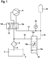
- FIG. 1 shows a schematic block diagram of a conventional device for injecting a fluid second
- the device has a reservoir 4, in which the fluid 2 to be injected is stored. Via a fluid extraction line 5, in which a filter 6 is arranged, the fluid 2 to be injected is removed from the reservoir 4 and through a 4/2-way switching valve 12, which is connected in normal operation in a first position 12 a, the input of a pump 8 supplied.
- the pump pressurizes the fluid 2 and supplies the fluid 2 to be injected under increased pressure through a second channel of the 4/2-way switching valve 12 to the injection and metering module 10, which is arranged and formed on an exhaust line (not shown) To inject the supplied fluid into the exhaust system. With the aid of a pressure sensor 18 arranged in or on the supply line, the pressure of the fluid can be continuously measured and monitored.
- a return line 16 which makes it possible to lead fluid from the injection and metering module 10 back to the input side of the pump 8 and in the reservoir 4.
- a 2/3-way throttle valve 14 is arranged, which is switchable between the three states: 14a interrupting the return line, 14b dosing function for setting a desired set pressure and 14c complete opening for the pulse-like suction of air.
- the Throttle valve 14 in the return line 16 can be set either one of the three operating states.
- the opening cross section of the throttle valve 14 can be varied to set a desired injection pressure.
- the 4/2-way switching valve 12 is switched to the second operating state 12b, in which the injection and metering module 10 with the input of the pump 8 and the filter 6 with the Output of the pump 8 are connected so that aspirated by operating the pump 8 fluid from the injection and metering module 10 and pumped through the filter 6 back into the reservoir 4.
- a second switchable valve 12 is required to allow pumping of fluid from the injection and metering module 10.
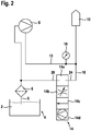
- FIG. 2 shows a schematic block diagram of an embodiment of an injection device according to the invention.
- An injection device has no 4/2-way switching valve 12 to connect the input and the output of the pump 8 optionally with the filter 6 or the injection and metering module 10. Rather, the input of the pump 8 (suction line) is permanent, i. without an intermediate (switching) valve, connected to the filter 6 and the output of the pump 8 (pressure line) is permanently connected to the injection and metering module 10.
- An injection device has a modified throttle valve 14, which is designed as a 2/4-way throttle valve 4 with two ports and four functions.
- a 2/4-way throttle valve 14 according to the invention in a pumping mode 14d switchable. In pumping mode 14d, it is possible to remove fluid from the injection and metering module 10 pump to the input of the pump 8 or through the filter 6 back into the reservoir 4.
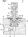
- FIG. 3 shows a sectional view of a 2/4-way throttle valve 14 according to the invention.
- the throttle valve 14 has a valve plate 22, in which a valve chamber 28, a first port 24 which is connected in the mounted state with the injection and metering module 10, and a second port 26, in the mounted state with the input of the pump. 8 and the filter 6, are formed as shown in the FIG. 2 is shown.
- a valve body 32 is arranged, which is movable along an axis A.
- the mouth of the first port 24 into the valve chamber 28 can be selectively opened and closed by moving the valve body 32.
- the cross section of the opening and thus the throttling action of the throttle valve 14 can be variably adjusted by moving the valve body 32 between a fully opened state and a fully closed state.
- the valve body 32 is mechanically connected to a slider 34, so that the valve body 32 is movable by moving the slider 34 parallel to the axis A between the closed and an open position.
- the spool 34 is guided outwardly by a flexible diaphragm 37 which defines and fluid-tightly seals one side of the valve space 28 and is provided by an external drive 38, e.g. is designed as a linear magnetic drive, driven.
- Spring elements 30, 36 which are arranged in the form of spiral springs around the valve member 32 and the slider 36 and are supported on this, press the valve member 32 and the slider 36 at rest, i. when the drive 38 is deactivated in the closed position, in which the valve element 32 closes the first connection 24 to the throttle chamber 28 in a fluid-tight manner.
- a protrusion 35 formed on the slider 34 cooperates with the flexible diaphragm 37 defining at least one side of the valve space 28, so that the diaphragm 37 is everted toward the outside opposite the valve space 28 when the slider 34 (in the illustration of FIGS Fig. 3 from bottom to top) from the closed to an open position becomes.
- the flexible membrane 37 By everting the flexible membrane 37, the volume of the valve chamber 28 is increased and the pressure in the valve chamber 28 is reduced.
- a first check valve 40 is provided which allows fluid flow from the first port 24 into the valve chamber 28 and prevents backflow of fluid from the valve chamber 28 into the first port 24.
- a second check valve 42 is provided in the second port 26 from the valve chamber 28, which allows fluid flow from the valve chamber 28 into the second port 26 and prevents fluid flow from the second port 26 into the valve chamber 28.
- valve body 32 and the spool 34 are urged (downwardly) by the spring members 30, 36 to the closed position in which the throttle valve 14 is fully closed, e.g. to allow complete venting of the injector.
- the slider 34 and the valve member 32 are movable (upwardly) to an open position. Rapid full opening of the throttle valve 14 with a quick movement of the valve body 32 in the fully open position causes a pulse-like suction of air into the injection and metering module 10, whereby there is an elastic air volume is created, which can accommodate the additional volume of freezing fluid and thereby increases the ice crushing strength of the injection and metering module 10.
- the pumping function of the throttle valve 14 according to the invention can be realized by periodically moving the slider 34.
- the slider 34 is moved toward the driver 38 by driving the driver 38 (upward) not only the valve body 32 is moved to an open position, but in addition, the flexible diaphragm 37 is slipped outward and the volume of the valve space 28 is increased ,
- valve space 28 Due to the pressure drop in the valve space 28 caused by the increase in the volume of the valve space 28, fluid 2 flows from the first port 24 through the check valve 40 opening in this flow direction into the valve space 28.
- the slider 34 is moved in the opposite direction (downwards) by a corresponding activation of the drive 38 or after deactivation of the drive 38 by the force of the spring elements 30, 36.
- the elastic membrane 37 which is connected to the slider 34 is moved in this case downwards in the direction of the valve plate 22 and thereby reduces the volume of the valve chamber 28.
- valve chamber 28 The reduction of the volume of the valve chamber 28 increases the pressure in the valve chamber 28 and the fluid flows from the valve chamber 28 through the second check valve 42 located in the second port 26 into the second port 26 and thence to the input side of the pump or back into the fluid reservoir 4 (see FIG FIG. 2 ).
- the two check valves 40, 42 are preferably designed so that they can be opened with the lowest possible force or low fluid pressure, so that they do not represent a noticeable resistance in the function "pulse-like back sucking", in which it depends on a rapid opening of the valves ,
- the volume of the valve chamber 28 is variable.
- the volume of the valve chamber 28 may increase by expanding the membrane 37 when the fluid in the pump chamber 28 freezes.
- the invention thus provides an injection device with an ice-pressure-resistant throttle valve 14.
- controllable throttle valve 14 from a 2/3-way throttle valve 14 to a 2/4-way throttle valve 14 with additional pump function reduces the complexity and cost of an injector, the suction of fluid from the injection and Dosing module 10 allows considerably.
Landscapes
- Chemical & Material Sciences (AREA)
- Engineering & Computer Science (AREA)
- Chemical Kinetics & Catalysis (AREA)
- Health & Medical Sciences (AREA)
- Toxicology (AREA)
- Combustion & Propulsion (AREA)
- Mechanical Engineering (AREA)
- General Engineering & Computer Science (AREA)
- Exhaust Gas After Treatment (AREA)
- Reciprocating Pumps (AREA)
- Nozzles (AREA)
Applications Claiming Priority (2)
| Application Number | Priority Date | Filing Date | Title |
|---|---|---|---|
| DE201110077953 DE102011077953A1 (de) | 2011-06-22 | 2011-06-22 | Einspritzvorrichtung |
| PCT/EP2012/059722 WO2012175282A1 (de) | 2011-06-22 | 2012-05-24 | Einspritzvorrichtung |
Publications (2)
| Publication Number | Publication Date |
|---|---|
| EP2723999A1 EP2723999A1 (de) | 2014-04-30 |
| EP2723999B1 true EP2723999B1 (de) | 2019-08-07 |
Family
ID=46149478
Family Applications (1)
| Application Number | Title | Priority Date | Filing Date |
|---|---|---|---|
| EP12723489.6A Active EP2723999B1 (de) | 2011-06-22 | 2012-05-24 | Einspritzvorrichtung |
Country Status (6)
Families Citing this family (8)
| Publication number | Priority date | Publication date | Assignee | Title |
|---|---|---|---|---|
| US9222388B2 (en) | 2013-02-28 | 2015-12-29 | Tenneco Automotive Operating Company Inc. | Urea common rail |
| CN103291423B (zh) * | 2013-06-13 | 2015-05-20 | 中国第一汽车股份有限公司无锡油泵油嘴研究所 | 一种还原剂供给装置 |
| WO2015188329A1 (en) | 2014-06-11 | 2015-12-17 | Tenneco Automotive Operating Company Inc. | Fluid delivery system with line pressure control valve |
| EP3228839B1 (en) | 2014-11-21 | 2019-09-25 | Tenneco (Suzhou) Emission System Co.,Ltd. | Common rail assembly, urea injection system and application thereof |
| CN105673154B (zh) | 2014-11-21 | 2019-11-08 | 天纳克(苏州)排放系统有限公司 | 共轨、该共轨的应用、尿素喷射系统及其控制方法 |
| CN106285864B (zh) * | 2016-10-26 | 2024-07-23 | 天纳克(苏州)排放系统有限公司 | 具有单向节流功能的尿素管、尿素喷射系统及其控制方法 |
| DE102017217891A1 (de) * | 2017-10-09 | 2019-04-11 | Robert Bosch Gmbh | Fördermodul zur Förderung eines Fluids |
| JP2020006870A (ja) * | 2018-07-11 | 2020-01-16 | ロベルト・ボッシュ・ゲゼルシャフト・ミト・ベシュレンクテル・ハフツングRobert Bosch Gmbh | 車両用のブレーキシステムの液圧制御ユニット |
Citations (2)
| Publication number | Priority date | Publication date | Assignee | Title |
|---|---|---|---|---|
| JPS59517A (ja) * | 1982-06-23 | 1984-01-05 | Mazda Motor Corp | デイ−ゼルエンジンの排気浄化装置 |
| DE102008036265A1 (de) * | 2008-08-04 | 2010-02-11 | J. Eberspächer GmbH & Co. KG | Abgasreinigungseinrichtung für Kraftfahrzeug |
Family Cites Families (11)
| Publication number | Priority date | Publication date | Assignee | Title |
|---|---|---|---|---|
| DE3719323A1 (de) * | 1987-06-10 | 1988-12-29 | Bosch Gmbh Robert | Vorrichtung zur betaetigung der drosselklappe einer brennkraftmaschine |
| FR2879239A1 (fr) * | 2004-12-15 | 2006-06-16 | Inergy Automotive Systems Res | Systeme de stockage et d'injection d'un additif dans des gaz d'echappement d'un moteur |
| DE102006012855A1 (de) * | 2006-03-21 | 2007-09-27 | Robert Bosch Gmbh | Verfahren und Dosiersystem zur Schadstoffreduktion in Kraftfahrzeugabgasen |
| JP4730278B2 (ja) * | 2006-10-20 | 2011-07-20 | 株式会社デンソー | エンジンの排気浄化装置 |
| DE102006060838A1 (de) | 2006-12-22 | 2008-06-26 | Purem Abgassysteme Gmbh & Co. Kg | Dosiersystem und Verfahren zum Betreiben eines Dosiersystems |
| US20100200786A1 (en) * | 2007-01-15 | 2010-08-12 | Pao-Lai Chen | Pressure-sensing valve and the method for using the same |
| DE102008009650A1 (de) * | 2008-02-18 | 2009-08-27 | Robert Bosch Gmbh | Störungssicheres System zur Schadstoffverminderung |
| JP5475243B2 (ja) * | 2008-03-07 | 2014-04-16 | ボッシュ株式会社 | 還元剤供給装置の制御装置及び還元剤の回収方法並びに排気浄化装置 |
| DE102008000594A1 (de) * | 2008-03-11 | 2009-09-17 | Robert Bosch Gmbh | Vorrichtung zum Entleeren einer Reduktionsmittelvorrichtung einer Brennkraftmaschine |
| JP5388286B2 (ja) * | 2009-06-19 | 2014-01-15 | ボッシュ株式会社 | 排気浄化装置及びその制御方法 |
| DE102009029534A1 (de) * | 2009-09-17 | 2011-03-24 | Robert Bosch Gmbh | Fördermodul sowie Dosiersystem mit einem solchen Fördermodul |
-
2011
- 2011-06-22 DE DE201110077953 patent/DE102011077953A1/de not_active Withdrawn
-
2012
- 2012-05-24 EP EP12723489.6A patent/EP2723999B1/de active Active
- 2012-05-24 JP JP2014516252A patent/JP5905090B2/ja not_active Expired - Fee Related
- 2012-05-24 CN CN201280030462.7A patent/CN103635665B/zh active Active
- 2012-05-24 WO PCT/EP2012/059722 patent/WO2012175282A1/de active Application Filing
- 2012-05-24 US US14/128,823 patent/US9222390B2/en not_active Expired - Fee Related
Patent Citations (2)
| Publication number | Priority date | Publication date | Assignee | Title |
|---|---|---|---|---|
| JPS59517A (ja) * | 1982-06-23 | 1984-01-05 | Mazda Motor Corp | デイ−ゼルエンジンの排気浄化装置 |
| DE102008036265A1 (de) * | 2008-08-04 | 2010-02-11 | J. Eberspächer GmbH & Co. KG | Abgasreinigungseinrichtung für Kraftfahrzeug |
Also Published As
| Publication number | Publication date |
|---|---|
| EP2723999A1 (de) | 2014-04-30 |
| JP2014520233A (ja) | 2014-08-21 |
| JP5905090B2 (ja) | 2016-04-20 |
| US9222390B2 (en) | 2015-12-29 |
| CN103635665A (zh) | 2014-03-12 |
| CN103635665B (zh) | 2017-10-27 |
| DE102011077953A1 (de) | 2012-12-27 |
| WO2012175282A1 (de) | 2012-12-27 |
| US20140116545A1 (en) | 2014-05-01 |
Similar Documents
| Publication | Publication Date | Title |
|---|---|---|
| EP2723999B1 (de) | Einspritzvorrichtung | |
| EP2748439B1 (de) | Dosiersystem für ein flüssiges reduktionsmittel | |
| EP1654456B1 (de) | Kraftstoff-einspritzvorrichtung für eine brennkraftmaschine | |
| EP2569522B1 (de) | Vorrichtung zur reduktion von schadstoffen im abgasstrom eines verbrennungsmotors | |
| DE102012208933A1 (de) | Einspritzsystem, Dosierpumpe, Abgasnachbehandlungseinrichtung, Verfahren | |
| DE102007000095B4 (de) | Kraftstoffeinspritzelement | |
| EP2603680B1 (de) | Einspritzvorrichtung zum einbringen einer harnstofflösung in den abgasstrang einer brennkraftmaschine | |
| WO2019166207A1 (de) | Einrichtung zur bereitstellung von unter einem vorgebbaren druck stehenden fluiden | |
| DE2456622C3 (de) | Selbsttätige Pumpeinrichtung | |
| DE102005022661A1 (de) | Fluidpumpe, insbesondere Kraftstoff-Hochdruckpumpe für eine Brennkraftmaschine mit Kraftstoff-Direkteinspritzung | |
| DE10153189A1 (de) | Kraftstoffpumpe, Kraftstoffsystem, Verfahren zum Betreiben eines Kraftstoffsystems sowie Brennkraftmaschine | |
| EP2011995A2 (de) | Injektor mit nach außen öffnendem Ventilelement | |
| DE19531064B4 (de) | Pulsationsfreie Pumpe | |
| DE102011112385A1 (de) | Ventilgesteuerte Kolbenmaschine und Verfahren zum Betreiben einer ventilgesteuerten Kolbenmaschine | |
| DE102007057446A1 (de) | Fluidfördereinrichtung und Ventileinrichtung sowie Verfahren zum Betreiben einer Fluidfördereinrichtung | |
| DE102011089516A1 (de) | Pumpe zum Rücksaugen für ein flüssiges Abgasnachbehandlungsmittel, Dosieranordnung und Verfahren zum Dosieren und Rücksaugen | |
| DE102011084995A1 (de) | Wegeventil mit integrierter Drossel | |
| DE19837213A1 (de) | Sammlerkraftstoffeinspritzeinrichtung | |
| DE102017222202A1 (de) | Kraftstofffördereinrichtung für kryogene Kraftstoffe | |
| DE102012205366B4 (de) | Fluidfördervorrichtung | |
| DE102011077946A1 (de) | Einspritzvorrichtung | |
| DE102012205370A1 (de) | 3/2-Wegeventil | |
| DE102012205367A1 (de) | 5/2-Wegeventil | |
| EP1348865A2 (de) | Hochdruck-Kraftstoffpumpe für ein Kraftstoffsystem einer Brennkraftmaschine | |
| DE2641203A1 (de) | Pumpvorrichtung zum einspritzen von kraftstoff |
Legal Events
| Date | Code | Title | Description |
|---|---|---|---|
| PUAI | Public reference made under article 153(3) epc to a published international application that has entered the european phase |
Free format text: ORIGINAL CODE: 0009012 |
|
| 17P | Request for examination filed |
Effective date: 20140122 |
|
| AK | Designated contracting states |
Kind code of ref document: A1 Designated state(s): AL AT BE BG CH CY CZ DE DK EE ES FI FR GB GR HR HU IE IS IT LI LT LU LV MC MK MT NL NO PL PT RO RS SE SI SK SM TR |
|
| DAX | Request for extension of the european patent (deleted) | ||
| STAA | Information on the status of an ep patent application or granted ep patent |
Free format text: STATUS: EXAMINATION IS IN PROGRESS |
|
| 17Q | First examination report despatched |
Effective date: 20161130 |
|
| GRAP | Despatch of communication of intention to grant a patent |
Free format text: ORIGINAL CODE: EPIDOSNIGR1 |
|
| STAA | Information on the status of an ep patent application or granted ep patent |
Free format text: STATUS: GRANT OF PATENT IS INTENDED |
|
| INTG | Intention to grant announced |
Effective date: 20190509 |
|
| GRAS | Grant fee paid |
Free format text: ORIGINAL CODE: EPIDOSNIGR3 |
|
| GRAA | (expected) grant |
Free format text: ORIGINAL CODE: 0009210 |
|
| STAA | Information on the status of an ep patent application or granted ep patent |
Free format text: STATUS: THE PATENT HAS BEEN GRANTED |
|
| AK | Designated contracting states |
Kind code of ref document: B1 Designated state(s): AL AT BE BG CH CY CZ DE DK EE ES FI FR GB GR HR HU IE IS IT LI LT LU LV MC MK MT NL NO PL PT RO RS SE SI SK SM TR |
|
| REG | Reference to a national code |
Ref country code: GB Ref legal event code: FG4D Free format text: NOT ENGLISH |
|
| REG | Reference to a national code |
Ref country code: CH Ref legal event code: EP Ref country code: AT Ref legal event code: REF Ref document number: 1164212 Country of ref document: AT Kind code of ref document: T Effective date: 20190815 |
|
| REG | Reference to a national code |
Ref country code: DE Ref legal event code: R096 Ref document number: 502012015125 Country of ref document: DE |
|
| REG | Reference to a national code |
Ref country code: IE Ref legal event code: FG4D Free format text: LANGUAGE OF EP DOCUMENT: GERMAN |
|
| REG | Reference to a national code |
Ref country code: NL Ref legal event code: MP Effective date: 20190807 |
|
| REG | Reference to a national code |
Ref country code: LT Ref legal event code: MG4D |
|
| PG25 | Lapsed in a contracting state [announced via postgrant information from national office to epo] |
Ref country code: LT Free format text: LAPSE BECAUSE OF FAILURE TO SUBMIT A TRANSLATION OF THE DESCRIPTION OR TO PAY THE FEE WITHIN THE PRESCRIBED TIME-LIMIT Effective date: 20190807 Ref country code: HR Free format text: LAPSE BECAUSE OF FAILURE TO SUBMIT A TRANSLATION OF THE DESCRIPTION OR TO PAY THE FEE WITHIN THE PRESCRIBED TIME-LIMIT Effective date: 20190807 Ref country code: FI Free format text: LAPSE BECAUSE OF FAILURE TO SUBMIT A TRANSLATION OF THE DESCRIPTION OR TO PAY THE FEE WITHIN THE PRESCRIBED TIME-LIMIT Effective date: 20190807 Ref country code: NO Free format text: LAPSE BECAUSE OF FAILURE TO SUBMIT A TRANSLATION OF THE DESCRIPTION OR TO PAY THE FEE WITHIN THE PRESCRIBED TIME-LIMIT Effective date: 20191107 Ref country code: SE Free format text: LAPSE BECAUSE OF FAILURE TO SUBMIT A TRANSLATION OF THE DESCRIPTION OR TO PAY THE FEE WITHIN THE PRESCRIBED TIME-LIMIT Effective date: 20190807 Ref country code: PT Free format text: LAPSE BECAUSE OF FAILURE TO SUBMIT A TRANSLATION OF THE DESCRIPTION OR TO PAY THE FEE WITHIN THE PRESCRIBED TIME-LIMIT Effective date: 20191209 Ref country code: BG Free format text: LAPSE BECAUSE OF FAILURE TO SUBMIT A TRANSLATION OF THE DESCRIPTION OR TO PAY THE FEE WITHIN THE PRESCRIBED TIME-LIMIT Effective date: 20191107 Ref country code: NL Free format text: LAPSE BECAUSE OF FAILURE TO SUBMIT A TRANSLATION OF THE DESCRIPTION OR TO PAY THE FEE WITHIN THE PRESCRIBED TIME-LIMIT Effective date: 20190807 |
|
| PG25 | Lapsed in a contracting state [announced via postgrant information from national office to epo] |
Ref country code: IS Free format text: LAPSE BECAUSE OF FAILURE TO SUBMIT A TRANSLATION OF THE DESCRIPTION OR TO PAY THE FEE WITHIN THE PRESCRIBED TIME-LIMIT Effective date: 20191207 Ref country code: GR Free format text: LAPSE BECAUSE OF FAILURE TO SUBMIT A TRANSLATION OF THE DESCRIPTION OR TO PAY THE FEE WITHIN THE PRESCRIBED TIME-LIMIT Effective date: 20191108 Ref country code: RS Free format text: LAPSE BECAUSE OF FAILURE TO SUBMIT A TRANSLATION OF THE DESCRIPTION OR TO PAY THE FEE WITHIN THE PRESCRIBED TIME-LIMIT Effective date: 20190807 Ref country code: ES Free format text: LAPSE BECAUSE OF FAILURE TO SUBMIT A TRANSLATION OF THE DESCRIPTION OR TO PAY THE FEE WITHIN THE PRESCRIBED TIME-LIMIT Effective date: 20190807 Ref country code: AL Free format text: LAPSE BECAUSE OF FAILURE TO SUBMIT A TRANSLATION OF THE DESCRIPTION OR TO PAY THE FEE WITHIN THE PRESCRIBED TIME-LIMIT Effective date: 20190807 Ref country code: LV Free format text: LAPSE BECAUSE OF FAILURE TO SUBMIT A TRANSLATION OF THE DESCRIPTION OR TO PAY THE FEE WITHIN THE PRESCRIBED TIME-LIMIT Effective date: 20190807 |
|
| PG25 | Lapsed in a contracting state [announced via postgrant information from national office to epo] |
Ref country code: TR Free format text: LAPSE BECAUSE OF FAILURE TO SUBMIT A TRANSLATION OF THE DESCRIPTION OR TO PAY THE FEE WITHIN THE PRESCRIBED TIME-LIMIT Effective date: 20190807 |
|
| RAP2 | Party data changed (patent owner data changed or rights of a patent transferred) |
Owner name: ROBERT BOSCH GMBH |
|
| PG25 | Lapsed in a contracting state [announced via postgrant information from national office to epo] |
Ref country code: PL Free format text: LAPSE BECAUSE OF FAILURE TO SUBMIT A TRANSLATION OF THE DESCRIPTION OR TO PAY THE FEE WITHIN THE PRESCRIBED TIME-LIMIT Effective date: 20190807 Ref country code: RO Free format text: LAPSE BECAUSE OF FAILURE TO SUBMIT A TRANSLATION OF THE DESCRIPTION OR TO PAY THE FEE WITHIN THE PRESCRIBED TIME-LIMIT Effective date: 20190807 Ref country code: EE Free format text: LAPSE BECAUSE OF FAILURE TO SUBMIT A TRANSLATION OF THE DESCRIPTION OR TO PAY THE FEE WITHIN THE PRESCRIBED TIME-LIMIT Effective date: 20190807 Ref country code: DK Free format text: LAPSE BECAUSE OF FAILURE TO SUBMIT A TRANSLATION OF THE DESCRIPTION OR TO PAY THE FEE WITHIN THE PRESCRIBED TIME-LIMIT Effective date: 20190807 Ref country code: IT Free format text: LAPSE BECAUSE OF FAILURE TO SUBMIT A TRANSLATION OF THE DESCRIPTION OR TO PAY THE FEE WITHIN THE PRESCRIBED TIME-LIMIT Effective date: 20190807 |
|
| PG25 | Lapsed in a contracting state [announced via postgrant information from national office to epo] |
Ref country code: SM Free format text: LAPSE BECAUSE OF FAILURE TO SUBMIT A TRANSLATION OF THE DESCRIPTION OR TO PAY THE FEE WITHIN THE PRESCRIBED TIME-LIMIT Effective date: 20190807 Ref country code: IS Free format text: LAPSE BECAUSE OF FAILURE TO SUBMIT A TRANSLATION OF THE DESCRIPTION OR TO PAY THE FEE WITHIN THE PRESCRIBED TIME-LIMIT Effective date: 20200224 Ref country code: CZ Free format text: LAPSE BECAUSE OF FAILURE TO SUBMIT A TRANSLATION OF THE DESCRIPTION OR TO PAY THE FEE WITHIN THE PRESCRIBED TIME-LIMIT Effective date: 20190807 Ref country code: SK Free format text: LAPSE BECAUSE OF FAILURE TO SUBMIT A TRANSLATION OF THE DESCRIPTION OR TO PAY THE FEE WITHIN THE PRESCRIBED TIME-LIMIT Effective date: 20190807 |
|
| REG | Reference to a national code |
Ref country code: DE Ref legal event code: R097 Ref document number: 502012015125 Country of ref document: DE |
|
| PLBE | No opposition filed within time limit |
Free format text: ORIGINAL CODE: 0009261 |
|
| STAA | Information on the status of an ep patent application or granted ep patent |
Free format text: STATUS: NO OPPOSITION FILED WITHIN TIME LIMIT |
|
| PG2D | Information on lapse in contracting state deleted |
Ref country code: IS |
|
| 26N | No opposition filed |
Effective date: 20200603 |
|
| PG25 | Lapsed in a contracting state [announced via postgrant information from national office to epo] |
Ref country code: SI Free format text: LAPSE BECAUSE OF FAILURE TO SUBMIT A TRANSLATION OF THE DESCRIPTION OR TO PAY THE FEE WITHIN THE PRESCRIBED TIME-LIMIT Effective date: 20190807 |
|
| PG25 | Lapsed in a contracting state [announced via postgrant information from national office to epo] |
Ref country code: MC Free format text: LAPSE BECAUSE OF FAILURE TO SUBMIT A TRANSLATION OF THE DESCRIPTION OR TO PAY THE FEE WITHIN THE PRESCRIBED TIME-LIMIT Effective date: 20190807 Ref country code: CH Free format text: LAPSE BECAUSE OF NON-PAYMENT OF DUE FEES Effective date: 20200531 Ref country code: LI Free format text: LAPSE BECAUSE OF NON-PAYMENT OF DUE FEES Effective date: 20200531 |
|
| REG | Reference to a national code |
Ref country code: BE Ref legal event code: MM Effective date: 20200531 |
|
| GBPC | Gb: european patent ceased through non-payment of renewal fee |
Effective date: 20200524 |
|
| PG25 | Lapsed in a contracting state [announced via postgrant information from national office to epo] |
Ref country code: LU Free format text: LAPSE BECAUSE OF NON-PAYMENT OF DUE FEES Effective date: 20200524 |
|
| PG25 | Lapsed in a contracting state [announced via postgrant information from national office to epo] |
Ref country code: GB Free format text: LAPSE BECAUSE OF NON-PAYMENT OF DUE FEES Effective date: 20200524 Ref country code: IE Free format text: LAPSE BECAUSE OF NON-PAYMENT OF DUE FEES Effective date: 20200524 |
|
| PG25 | Lapsed in a contracting state [announced via postgrant information from national office to epo] |
Ref country code: BE Free format text: LAPSE BECAUSE OF NON-PAYMENT OF DUE FEES Effective date: 20200531 |
|
| REG | Reference to a national code |
Ref country code: AT Ref legal event code: MM01 Ref document number: 1164212 Country of ref document: AT Kind code of ref document: T Effective date: 20200524 |
|
| PGFP | Annual fee paid to national office [announced via postgrant information from national office to epo] |
Ref country code: FR Payment date: 20210521 Year of fee payment: 10 |
|
| PG25 | Lapsed in a contracting state [announced via postgrant information from national office to epo] |
Ref country code: AT Free format text: LAPSE BECAUSE OF NON-PAYMENT OF DUE FEES Effective date: 20200524 |
|
| PG25 | Lapsed in a contracting state [announced via postgrant information from national office to epo] |
Ref country code: MT Free format text: LAPSE BECAUSE OF FAILURE TO SUBMIT A TRANSLATION OF THE DESCRIPTION OR TO PAY THE FEE WITHIN THE PRESCRIBED TIME-LIMIT Effective date: 20190807 Ref country code: CY Free format text: LAPSE BECAUSE OF FAILURE TO SUBMIT A TRANSLATION OF THE DESCRIPTION OR TO PAY THE FEE WITHIN THE PRESCRIBED TIME-LIMIT Effective date: 20190807 |
|
| PG25 | Lapsed in a contracting state [announced via postgrant information from national office to epo] |
Ref country code: MK Free format text: LAPSE BECAUSE OF FAILURE TO SUBMIT A TRANSLATION OF THE DESCRIPTION OR TO PAY THE FEE WITHIN THE PRESCRIBED TIME-LIMIT Effective date: 20190807 |
|
| PG25 | Lapsed in a contracting state [announced via postgrant information from national office to epo] |
Ref country code: FR Free format text: LAPSE BECAUSE OF NON-PAYMENT OF DUE FEES Effective date: 20220531 |
|
| PGFP | Annual fee paid to national office [announced via postgrant information from national office to epo] |
Ref country code: DE Payment date: 20240726 Year of fee payment: 13 |