EP2723536B1 - Exoskeleton - Google Patents
Exoskeleton Download PDFInfo
- Publication number
- EP2723536B1 EP2723536B1 EP12731302.1A EP12731302A EP2723536B1 EP 2723536 B1 EP2723536 B1 EP 2723536B1 EP 12731302 A EP12731302 A EP 12731302A EP 2723536 B1 EP2723536 B1 EP 2723536B1
- Authority
- EP
- European Patent Office
- Prior art keywords
- exoskeleton
- joint
- linear bearings
- human
- axes
- Prior art date
- Legal status (The legal status is an assumption and is not a legal conclusion. Google has not performed a legal analysis and makes no representation as to the accuracy of the status listed.)
- Active
Links
Images


Classifications
-
- B—PERFORMING OPERATIONS; TRANSPORTING
- B25—HAND TOOLS; PORTABLE POWER-DRIVEN TOOLS; MANIPULATORS
- B25J—MANIPULATORS; CHAMBERS PROVIDED WITH MANIPULATION DEVICES
- B25J9/00—Programme-controlled manipulators
- B25J9/0006—Exoskeletons, i.e. resembling a human figure
-
- A—HUMAN NECESSITIES
- A61—MEDICAL OR VETERINARY SCIENCE; HYGIENE
- A61H—PHYSICAL THERAPY APPARATUS, e.g. DEVICES FOR LOCATING OR STIMULATING REFLEX POINTS IN THE BODY; ARTIFICIAL RESPIRATION; MASSAGE; BATHING DEVICES FOR SPECIAL THERAPEUTIC OR HYGIENIC PURPOSES OR SPECIFIC PARTS OF THE BODY
- A61H1/00—Apparatus for passive exercising; Vibrating apparatus; Chiropractic devices, e.g. body impacting devices, external devices for briefly extending or aligning unbroken bones
- A61H1/02—Stretching or bending or torsioning apparatus for exercising
- A61H1/0237—Stretching or bending or torsioning apparatus for exercising for the lower limbs
- A61H1/024—Knee
-
- A—HUMAN NECESSITIES
- A61—MEDICAL OR VETERINARY SCIENCE; HYGIENE
- A61H—PHYSICAL THERAPY APPARATUS, e.g. DEVICES FOR LOCATING OR STIMULATING REFLEX POINTS IN THE BODY; ARTIFICIAL RESPIRATION; MASSAGE; BATHING DEVICES FOR SPECIAL THERAPEUTIC OR HYGIENIC PURPOSES OR SPECIFIC PARTS OF THE BODY
- A61H1/00—Apparatus for passive exercising; Vibrating apparatus; Chiropractic devices, e.g. body impacting devices, external devices for briefly extending or aligning unbroken bones
- A61H1/02—Stretching or bending or torsioning apparatus for exercising
- A61H1/0274—Stretching or bending or torsioning apparatus for exercising for the upper limbs
- A61H1/0281—Shoulder
-
- B—PERFORMING OPERATIONS; TRANSPORTING
- B25—HAND TOOLS; PORTABLE POWER-DRIVEN TOOLS; MANIPULATORS
- B25J—MANIPULATORS; CHAMBERS PROVIDED WITH MANIPULATION DEVICES
- B25J9/00—Programme-controlled manipulators
- B25J9/0003—Home robots, i.e. small robots for domestic use
-
- A—HUMAN NECESSITIES
- A61—MEDICAL OR VETERINARY SCIENCE; HYGIENE
- A61H—PHYSICAL THERAPY APPARATUS, e.g. DEVICES FOR LOCATING OR STIMULATING REFLEX POINTS IN THE BODY; ARTIFICIAL RESPIRATION; MASSAGE; BATHING DEVICES FOR SPECIAL THERAPEUTIC OR HYGIENIC PURPOSES OR SPECIFIC PARTS OF THE BODY
- A61H2201/00—Characteristics of apparatus not provided for in the preceding codes
- A61H2201/12—Driving means
- A61H2201/1207—Driving means with electric or magnetic drive
-
- A—HUMAN NECESSITIES
- A61—MEDICAL OR VETERINARY SCIENCE; HYGIENE
- A61H—PHYSICAL THERAPY APPARATUS, e.g. DEVICES FOR LOCATING OR STIMULATING REFLEX POINTS IN THE BODY; ARTIFICIAL RESPIRATION; MASSAGE; BATHING DEVICES FOR SPECIAL THERAPEUTIC OR HYGIENIC PURPOSES OR SPECIFIC PARTS OF THE BODY
- A61H2201/00—Characteristics of apparatus not provided for in the preceding codes
- A61H2201/16—Physical interface with patient
- A61H2201/1602—Physical interface with patient kind of interface, e.g. head rest, knee support or lumbar support
- A61H2201/1614—Shoulder, e.g. for neck stretching
- A61H2201/1616—Holding means therefor
-
- A—HUMAN NECESSITIES
- A61—MEDICAL OR VETERINARY SCIENCE; HYGIENE
- A61H—PHYSICAL THERAPY APPARATUS, e.g. DEVICES FOR LOCATING OR STIMULATING REFLEX POINTS IN THE BODY; ARTIFICIAL RESPIRATION; MASSAGE; BATHING DEVICES FOR SPECIAL THERAPEUTIC OR HYGIENIC PURPOSES OR SPECIFIC PARTS OF THE BODY
- A61H2201/00—Characteristics of apparatus not provided for in the preceding codes
- A61H2201/16—Physical interface with patient
- A61H2201/1657—Movement of interface, i.e. force application means
- A61H2201/1664—Movement of interface, i.e. force application means linear
Definitions
- Powered exoskeletons are used for example for robot-assisted rehabilitation of patients having neurological injuries.
- joints are required that have motion capabilities that correspond to the motion capabilities of humans.
- Neurological injuries are the leading cause of serious, long-term disability. Each year about 15 million people suffer a stroke. According to the National Stroke Association of US, the estimated the cost per patient in the first 3 months of treatment is about 15 thousand dollars. Moreover, for 10% of cases theses cost exceed 35 thousand dollars. The situation gets even more serious with the ageing of the population, in particular, in the EU countries and Japan.
- robot-mediated rehabilitation therapy allows quantitative measurements of patient progress and can be used to realize customized, interactive treatment protocols.
- Rehabilitation robots increase the reliability, accuracy, and effectiveness of traditional physical rehabilitation therapies, enable active participation of patients by assisting patients only as-needed, render easy tuning of duration and intensity of therapies feasible, can be applied to patients with all levels of impairment, motivate patients to endure intense therapy sessions thanks to virtual reality integration, and are capable of realizing new treatment protocols with virtual environments and haptic feedback.
- beneficial effects of robot assisted rehabilitation over conventional physical therapy have been shown through clinical trials.
- Upper-limb rehabilitation devices can be categorized in three main categories: end-effector type robots, cable suspension systems and exoskeletons.
- End-effector type rehabilitation robots feature a single interaction point (the end-effector) with the patient and the joint motions of these devices do not correspond to human movements. Therefore, without external restraints applied to constrain the patient, joint specific therapies cannot be delivered by such mechanisms. Moreover, compensatory movements of the patient cannot be detected when these devices are used.
- end-effector type robots are advantageous thanks to their simple kinematic structure and low cost.
- MIT-Manus is an impedance-type robot that possesses two grounded direct-drive motors to provide torques to assist or resist patient movements.
- Another example of such devices is the Gentle/s, which uses an admittance-type robot (HapticMaster) along with a gimbal mechanism to connect to the human wrist.
- Reha-Slide is another fixed base device which is designed to administer resistive movement therapies. Reha-Slide has two holders which are horizontally placed on a table and enables forward and backward arm movements.
- End-effector type robots have also been used to impose bimanual exercises.
- MIME system based on an admittance controlled 6 degrees-of-freedom (DoF) PUMA robot has been used to deliver mirror image therapies.
- DoF degrees-of-freedom
- Cable suspension devices help mobilize the upper-limb of the body by compensating for the gravitational forces. These devices are passive systems with simple kinematic structure; therefore, cable suspension devices are low cost. However, these devices cannot assist or resist to patients while completing therapeutic tasks and they lack measurement capabilities.
- exoskeletons are attached to the human limb at multiple interaction points and movement of these devices correspond with human joints.
- exoskeletons are capable of applying controlled torques to individually targeted joints and measuring the movements of these specific joints decoupled from movements of the other joints.
- exoskeletons possess more complex kinematic structure compared to end-effector type robots and hence are more costly.
- the exoskeletons can be further grouped into three categories.
- Orthoses constitute the first group of exoskeletons. Orthoses aim to physically support people while performing daily tasks. HAL-5 full-body exoskeleton is an example of such orthoses ("Robot suit HAL", http://ww.cyberdyne.jp/english/ robotsuithal/index.html). Another example of such orthoses is the Myomo robot ("Myomo,” http://www.myomo.com/ myomo_product_stroke_rehabilitation_arm_brace_technology_overview.asp), an elbow orthosis. Another well-known orthoses is the Rewalker (A. Goffer, "Gait-locomotor apparatus", US Patent 7,153,242 ). In contrast to Myomo, Rewalker orthoses is specifically built for lower limb to support users during gait movements.
- the second group is composed of the augmentation exoskeletons. These robots are designed for healthy users and aim help users to achieve heavy duty tasks that require high muscle power.
- Exos ArmMaster V. Bin Massie, Thomas AN. H.; Vayner", Sensory feedback exoskeleton armmaster," patent appliaction WO/1995/032 842
- an upper-extremity exoskeleton with 5 DoF is another example of augmentation exoskeletons.
- BLEEX A. Zoss, H. Kazerooni, and A. Chu, "Biomechanical design of the berkeley lower extremity exoskeleton (BLEEX),” Mechatronics, IEEE/ASME Transactions on, vol. 11, no.
- BLEEX is a lower-extremity exoskeleton developed to augment muscle power of people who work on rough terrains for long time.
- Another exoskeleton deigned for human augmentation is the XOS 2 robot ("XOS 2 Exoskeleton", http://www.raytheon.com/newsroom/technology/rtno8_exoskeleton/).
- XOS 2 is also designed for physically challenging tasks; however, XOS 2 is for the upper body.
- the third group of exoskeletons is designed specifically for rehabilitation. Unlike the other two groups, rehabilitation robots are designed for clinical use. Consequently, most of the robots on this group are grounded to a fixed base and are immobile.
- a well-known example of rehabilitation exoskeletons is the ARMin robot ( T. Nef, M. Mihelj, G. Kiefer, C. Perndl, R. Muller, and R. Riener, "ARMin - Exoskeleton for arm therapy in stroke patients," in Re-habilitation Robotics, 2007. ICORR 2007. IEEE 10th International Conference on, 2007, pp. 68 -74 ).
- the first version of this robot, ARMin I is composed of an exoskeleton elbow and forearm robot attached to an end-effector type shoulder mechanism.
- the shoulder mechanism of ARMin I is modeled as a 3 DoF spherical joint. Since human shoulder has 5 DoF, ARMin I is unable to impose ergonomic movements to patients.
- ARMin II M. Mihelj, T. Nef, and R. Riener, "ARMin II - 7 DoF rehabilitation robot: mechanics and kinematics," in Robotics and Automation, 2007 IEEE International Conference on, 2007, pp. 4120 - 4125
- ARMin III T. Nef, M. Guidali, and R. Riener, "ARMin III - Arm therapy exoskeleton with an ergonomic shoulder actuation,” Applied Bionics and Biomechanics, vol. 6, no. 2, pp.
- the shoulder joint is simplified by eliminating passive robot elements and ergonomic movement is achieved by circular shoulder joint movement. Since the ARMin III has a simpler kinematic structure, the cost is decreased with respect to ARMin II, consequently the ergonomy of the robot is deteriorated as well. As a result ARMin III cannot fully correspond to human joints.
- Ergonomic shoulder joint is one of the major design criteria for the MGA exoskeleton robot ( C. Carignan, M. Liszka, and S. Roderick, "Design of an arm exoskeleton with scapula motion for shoulder rehabilitation," in Advanced Robotics, 2005. ICAR'05. Proceedings., 12th International Confer-ence on, 2005, pp. 524 -531 ). Similar to ARMin III, MGA exoskeleton also models the shoulder movements on a circular path to sustain ergonomy. In particular, MGA exoskeleton allows for active adjustment to scapula rotation through use of an extra actuated revolute joint in series with 3 actuators forming a spherical joint. Hence, MGA exoskeleton cannot account for all 5 DoF movement of the human shoulder and adjustment of link lengths are necessary for each patient such that the resulting shoulder movement closely approximates the real one.
- Dampace exoskeleton is a fully passive brake based rehabilitation robot that uses passive alignment mechanisms to account for glenohumeral mobilization ( A. Stienen, E. Hekman, F. Van der Helm, G. Prange, M. Jannink, A. Aalsma, and H. Van der Kooij, "DAMPACE: Dynamic force-coordination trainer for the upper extremities," in Rehabilitation Robotics, 2007, ICORR 2007, IEEE 10th International Conference on, 2007, pp. 820 -826 ).
- the robot has 4 DoFs controlled DoF, in which 3 DoFs is on the shoulder and 1 DoF on the elbow. However, there is also a 2 DoF self-alignment mechanism on the shoulder which can account for scapulohumeral rhythm.
- Dampace possesses a passive gravity compensation mechanism which allows only a small portion of the robot weight be transmitted by the user.
- Limpact A. Stienen, E. Hekman, H. ter Braak, A. Aalsma, F. van der Helm, and H. van der Kooij, "Design of a rotational hydroelastic actuator for a powered exoskeleton for upper limb rehabilitation," Biomedical Engineering, IEEE Transactions on, vol. 57, no. 3, pp. 728 -735, 2010
- This exoskeleton also features passive alignment for the shoulder joint and is hydraulically actuated. Passive alignment mechanisms cannot assist/resist patients during glenohumeral mobilization exercises. Moreover, such mechanisms cannot bear large forces.
- L-exos robot uses a cable driven actuation system to place the motor of the robot outside the exoskeleton and decrease the weight ( A. Frisoli, M. Bergamasco, M. Carboncini, and B. Rossi, "Robotic assisted rehabilitation in virtual reality with the L-EXOS.” Stud Health Technol Inform, vol. 145, pp. 40-54, 2009 ).
- CADEN-7 is another cable driven exoskeleton ( J. Perry, J. Rosen, and S. Burns, "Upper-limb powered exoskeleton design", Mechatronics, IEEE/ASME Transactions on, vol. 12, no. 4, pp. 408 -417, 2007 ).
- CADEN-7 is different from the L-exos with an additional joint on the wrist mechanism, correspondingly allows a wider range of exercises.
- T-WREX R. Sanchez, J. Liu, S. Rao, P. Shah, R. Smith, T. Rahman, S. Cramer, J. Bobrow, and D. Reinkensmeyer
- T-WREX robot has 2 motors to activate the shoulder joint and a third motor is attached serially to move the whole shoulder mechanism in a circular trajectory.
- the shoulder joint of the robot consists of 4 DoFs, in which two of them is coupled; therefore, the robot cannot fully correspond to human shoulder for all patients.
- a disclosed robotic exoskeleton comprises mechanical linkage that couples to a selected joint of a limb of a subject.
- SAM exoskeleton manages mobility in addition to being light weight ( P. Letier, M. Avraam, S. Veillerette, M. Horodinca, M. De Bartolomei, A. Schiele, and A. Preumont”, SAM: A 7-DoF portable arm exoskeleton with local joint control", in Intelligent Robots and Systems, 2008. IROS 2008. IEEE/RSJ International Conference on, 2008, pp. 3501 - 3506 ).
- the robot is 7 DoFs mechanism, in which 3 DoFs are allocated for shoulder joint movements. Consequently, although SAM offers mobility, it cannot preserve joint correspondence for ergonomic therapy. Another consideration for rehabilitation exoskeleton design is to achieve high stiffness.
- the ABLE exoskeleton which has 4 DoFs, is designed to carry high forces acting on the hand module of the robot ( P. Garrec, J. Friconneau, Y. Measson, and Y. Perrot, "ABLE, an innovative transparent exoskeleton for the upper-limb", in Intelligent Robots and Systems, 2008, IROS 2008, IEEE/RSJ International Conference on, 2008, pp. 1483 - 1488 ). Since the whole arm of the robot is modeled as 4 DoFs, the robot cannot fully sustain joint alignment.
- anterior-posterior translations The translation of the joint axis, called anterior-posterior translations.
- the kinematic models of the knee suggest that the magnitude of anterior-posterior translations can exceed 19 mm for a healthy human ( Y. Li, J. Huegel, V. Patoglu, and M. O'Malley, "Progressive shared control for training in virtual environments", in EuroHaptics conference, 2009 and Symposium on Haptic Interfaces for Virtual Environment and Teleoperator Systems. World Haptics 2009, Third Joint, 2009, pp. 332 - 337 ).
- an exoskeleton for humans comprising a joint element that interacts directly or indirectly with a human's joint via an end-effector mount, wherein the end-effector mount is arranged to perform an arbitrary planar parallel movement in a plane, allowing superimposed translational and rotational movements of the end-effector mount relative to a body of the joint element.
- Such a set-up of an exoskeleton allows for an excellent adjustment of the joint axes, i.e. the exoskelleton's and the human's joint, guaranteeing simultaneous translational and rotational movements.
- the exoskeleton is self-aligning to the movements of a human's joint independent from differences in the attachment of the exoskeleton to the body and anatomical differences of the patients.
- the joint element comprises a parallel mechanism, preferably a 3-RPR, 3-RRR, 3-PRR, 3-RRP, or 3PRP mechanism.
- a parallel mechanism preferably a 3-RPR, 3-RRR, 3-PRR, 3-RRP, or 3PRP mechanism.
- Such parallel mechanism enables arbitrary movement and rotation in a plane allowing the desired movement of the end-effector mount.
- the end-effector mount comprises at least three translational axes, wherein the axes are rigidly connected to the end-effector mount, wherein the axes are arranged parallel to plane of the arbitrary planar parallel movement of the end effector and wherein the axes are arranged having an angle to each other.
- the end effector comprises three translational axes and the angle between two axes is 100° - 140°, preferably 120°.
- the use of three axes ensures a geometrically defined movement of the end-effector mount while simultaneously minimizing the friction.
- the angle range between the axes further supports this definition of movement and improved friction.
- the exoskeleton's joint element is self-aligning with respect to the human's joint that it interacts with. This is one of the important advantages of the current device, as the set-up of phase can be significantly shortened as compared to the one required when working with current rehabilitation devices.
- the axes are respectively guided by linear bearings, wherein the linear bearings are independently movable on one or more circular path(s) relative to the body, wherein the circular paths are arranged in parallel to the plane of the arbitrary planar parallel movement of the end-effector mount.
- This construction of the joint element provides an improved kinematics for allowing an arbitrary planar parallel movement in a plane of the end-effector mount.
- the linear bearings are movable along one common circular path.
- This provides for a compact construction, however, different circular paths can also be envisioned, wherein, for example, the range of the end-effector mount is specifically increased only in one direction.
- the linear bearings of the exoskeleton are respectively supported by a rotational bearing with respect to the circular path(s), wherein the rotation axes of the rotational bearings is arranged perpendicular to the plane of the arbitrary planar parallel movement of the end-effector mount.
- the axes comprise straight links that are supported in corresponding openings of the linear bearings.
- the rotational bearings are connected to co-centred rings.
- one or more or all of the linear bearings of the exoskeleton are actively independently driven along the circular path(s) by respective motors that preferably drive said co-centred rings.
- a human's joint can be actively moved in its natural complexity, comprising superimposed translational and rotational movements.
- one or more or all of the linear bearings of the exoskeleton are actively independently driven along the circular path(s) by cable based actuators that preferably drive said co-centred rings.
- cable based actuators that preferably drive said co-centred rings.
- Different actuation and transmission methods are possible including electric motors, cables, springs, hydraulics or the like.
- the joint element is passively driven by arranging the end-effector mount of the exoskeleton so as to drive one or more or all of the linear bearings by the movements of the human's joint within the plane of the planar parallel movement.
- the joint element thus allows to be moved passively by translational movements of the human's joint. This can be used to measure the possible motions or forces or both of a human's joint or to apply a resistance to the human's movements by means of the exoskeleton.
- one or more or all linear bearings are resisted with resisting elements like springs.
- resisting elements like springs.
- the exoskeleton can for example be uses as measuring device that measures under load or as training device.
- the exoskeleton further comprises force application means for exerting a resistance to the induced movement of the linear bearings.
- force application means for exerting a resistance to the induced movement of the linear bearings.
- the exoskeleton comprises a force/torque sensor attached to the end-effector mount for measuring the force/torque exerted to or by the human's joint.
- one or more linear bearings are actively independently driven and the remaining linear bearings are resisted with resisting elements like springs or brakes.
- resisting elements like springs or brakes.
- some degrees of freedom are actuated and other degrees of freedom are resisted with springs, brakes or the like.
- the exoskeleton further comprises measuring devices for measuring or registering the motion, force or their relation of the human's joint. This is useful for diagnostic purposes as well as for the determination of the progress during rehabilitation. By measuring the relationship between human's joint motion and human's joint force cases like impedance/tonus measurements are possible.
- the exoskeleton 1 can be used at many human joints, including but not limited to knee, shoulder, hip/pelvis, ankle, and spine.
- a parallel mechanism as illustrated in Fig. 13 in six variations, can be used as underlying mechanism for implementing a joint element 2 for an exoskeleton 1 according to the invention.
- the use of such a kinematics in an exoskeleton 1 for rehabilitation, human augmentation, human measurement and many other purposes ensures ergonomy, large range of motion for joint movements, the ability to deliver and measure joint translations together with joint rotations, allows an ease of attachment due to no calibration requirements and many other advantages.
- the exoskeleton can of course also be used for animals.
- A3- R RP mechanism is preferred as the underlying mechanism for implementation of self-aligning joint element, since this mechanism is capable of sustaining all necessary movements to cover the complex movement of the joints whose axis of rotation are not fixed.
- the 3- R RP planar parallel mechanism possesses 3 DoF, which include translations in plane and rotation along perpendicular axis. Thanks to its kinematic structure with close kinematic chains, the 3- R RP mechanism features high bandwidth and position accuracy when compared with its serial counterparts.
- the workspace of 3- R RP mechanism covers a large range of rotations, which is necessary for implementation of the shoulder joint whose rotation typically exceeds 180 during flexion and extension exercises.
- 3- R RP means that the mechanism comprises 3 joints, wherein each of the three joints allows rotation around two different rotational axes and allows displacement along one prismatic axis.
- the underlining indicates that one rotational axis is actuated.
- the 3- R RP mechanism comprises three axes 16, 26, 36 that are respectively guided by three joints (bearings 10, 20, 30) which respectively rotate around a vertical axis through point O causing circular paths 14, 24, 34 of the bearings 10, 20, 30 (" R "), additionally rotate around vertical rotational bearings 12, 22, 32 (“R”) and finally allow a linear displacement ("P") of links 17, 27, 37 within the bearings 10, 20, 30.
- the links 17, 27, 37 are collinear with the respective axes 16, 26, 36.
- the 3- R RP mechanism used in the joint element 2 consists of five rigid bodies 3, 18, 28, 38 and a symmetric body 4.
- Body 3 represents the fixed frame
- bodies 18, 28 and 38 have simple rotations about the fixed link about point O
- the symmetric end effector mount 4 is attached to bodies 18, 28 and 38 through linear bearings 10, 20, 30 and rotational bearing 12, 22, 32 collocated at points P, Q and R , respectively.
- the common out of the plane unit vector is denoted by k and basis vectors of each body are indicated in Figure 6 .
- the point O is fixed in body 3
- point P is fixed in body 28
- point Q is fixed in body 18
- point R is fixed in body 38
- point Z is fixed in end effector mount 4.
- the fixed distance OP is defined as l 1
- OQ is defined as l 2
- OR is defined as l 3
- ZP is defined as s 1
- ZQ is defined as s 2
- ZR is defined as s 3 .
- the angle between the line l and t 1 vector is q 1
- the angle between 1 s 1 and is q 2
- the angle between l and v 1 is q 3 . All angles are positive when measured counter clockwise.
- the inputs to the mechanism are set as the angles q 1 , q 2 and q 3 (i.e. the links S, T and V are actuated) and their time derivatives.
- e 1 vector is parallel to n 1 .
- the output of the system is defined as the position of the end-effector mount point Z , when measured from the fixed point O and the orientation of body E, measured with respect to body N.
- Both forward and inverse kinematics of the exoskeleton are derived at configuration and motion levels, respectively.
- Figure 7 shows a self-aligning joint element 2 of the exoskeleton 1 based on the 3- R RP mechanism that can be applied e.g. to knee or shoulder joints.
- the rings of the element 2 18, 28, 38 are manufactured from aluminum and each ring 18, 28, 38 is supported with three auxiliary parts 50a, 50b, 50c with three ball shaped teflon rollers 52a, 52b, 52c.
- a belt drive transmission is utilized to transfer power from direct drive motors 15, 25, 35 to the rings 18, 28, 38 using timing belts 11 that are respectively fixed to the aluminum rings 18, 28, 38 and aluminum pulleys 13, 23, 33 that are respectively attached to the transmission axle of each direct drive motor 15, 25, 35.
- the transmission ratio is set to 25 for the shoulder and 5.6 for the knee joint application.
- the belts 11 are placed inside the rings 18, 28, 38, such that the actuators of the robot can be located inside the rings, decreasing mechanism footprint.
- belt drive provides torque amplification while simultaneously enabling concentric placement of the three rings 18, 28, 38.
- Belt drives are preferred due to their low cost and widespread availability with various sizes and properties.
- the movements of the rings 18, 28, 38 are transferred to an upper planar plane by using aluminum links 80, 90, 100 and these aluminum links 80, 90, 100 are merged with links 17, 27, 37, preferably carbon fiber tubes, via linear and rotational bearings.
- the carbon fiber tubes, that enable a low weight and high stiffness implementation of the end-effector mount 4 are connected to the end-effector mount 4 of the joint element 2 with 120° angle between each tube 19, 29, 39.
- the exoskeleton is actuated using direct-drive graphite-brushed DC motors that possess 180 mNm continuous torque output. Direct drive actuators are preferred since they are highly back-driveable. Optical encoders attached to the motors have a resolution of 2000 counts per revolution, under quadrature decoding.
- the robot is designed to feature a symmetric structure, such that it possesses high kinematic isotropy and can be applied to both left and right limbs.
- a first prototype of the self-aligning joint element has a large translational workspace, covering up to 120 mm translations along x and y axes for the shoulder or 180 mm translations along x and y axes for the knee joint application, respectively.
- the self-aligning joint element can also sustain infinite rotations about the perpendicular axis.
- Figure 5 shows the exoskeleton attached to a human knee.
- figure 3 illustrates the self-aligning joint element implemented in a shoulder-elbow exoskeleton.
- Figure 14 shows another embodiment of a joint element 2 that is driven via cable based actuators.
- the actuators (not shown) drive Bowden cables 60, 62, 64 that drive rings 18, 28, 38 in a pulley like fashion.
- the inner cables of the Bowden cables 60, 62, 64 are guided around the outer circumference of the rings 18, 28, 38.
- the linear bearings 10, 20, 30 are attached to the driven rings 18, 28, 38 via links.
- the Bowden Cables 60, 62, 64 can be used to transfer the movements of the end-effector mount 4 to sensors or resisting elements like springs or brakes (not shown) if the exoskeleton is passively driven by the human's motion attached to it.
- the joint self-aligning joint element 2 and thus the exoskeleton 1 is highly back-driveable.
- a model-based open-loop impedance controller for the self-aligning joint element 2 controlling interaction forces, alleviating the need for force sensors.
- the overall control architecture used to control the device is depicted in Figure 11 . Note that to increase the fidelity impedances rendered by the impedance controller, the end-effector mount 4 can still be equipped with a force/torque sensor 40, 41 enabling implementation of closed-loop impedance control.
- the measured actuator velocities are multiplied with the Jacobian matrix and the actual end-effector mount velocities are obtained.
- the difference of the actual and desired end-effector mount velocities are fed to the impedance controller and desired forces are calculated.
- desired forces are multiplied with the Jacobian transpose matrix and desired joint torques are obtained.
- the desired joint torques are added with the feed-forward torques estimated using the dynamic model of the joint element, that is, Coriolis, centrifugal and gravity matrices. Since disturbances acting on the joint element are physical and changes according to the environment, the total torque applied to the physical joint element includes these parasitic effects. If a force sensor 41 is available to measure the forces applied at end-effector mount 4, then the difference between the measured and desired values of the forces can be fed to a force controller, implementing a closed-loop controller.
- Table I presents the characterization results of a 3 - R RP self-aligning joint element.
- Instantaneous peak and continuous end-effector mount forces along x and y directions are determined as 1 kN and 80 N, respectively.
- instantaneous peak and continuous end-effector mount forces along the rotational axis are found as 170 Nm and 12.5Nm, respectively.
- the end-effector mount resolutions are calculated to be 0.3252 mm along x, 0.5633 mm along y directions and 0.0031 rad on the rotational direction.
- the workspace of the self-aligning joint element 2 spans a range from -60 mm to 60 mm along x and y directions, while the joint element is capable of performing infinite rotations about the perpendicular axis.
- the stability limits for virtual wall rendering are observed as 50 kN/m along x direction, 42 kN/m along y direction and 1 kN/rad on rotation.
- the characterization results verify that the self-aligning joint element 2 is highly back-driveable and that can be moved with a 3 N force along x and y directions. As a result of being back-driveable, the exoskeleton 1 comprising the joint element 2 can ensure safety even under power loss.
- table II presents the experimental characterization results of a 3- R RP knee exoskeleton.
- Instantaneous peak and continuous end-effector mount forces along x and y directions are determined as 246.7 N and 18.4 N, respectively.
- instantaneous peak and continuous end-effector mount forces along the rotational axis are found as 38.2 Nm and 2.85 Nm, respectively.
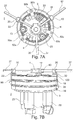
- Figure 8 presents an embodiment design with built in force/torque sensing
- the design in Figure 9 features series-elastic actuation
- a variable-impedance design that utilizes antagonist actuation is depicted in Figure 10 .
- the force sensing for close-loop force/impedance control is possible by attaching a multi-axis force/torque (F/T) sensor 40, 41 to the end-effector mount 4.
- F/T force/torque
- other low-cost solutions can also be implemented.
- low-cost, single-axis force and torque cells can be embedded to the end-effector mount 4 of the mechanism.
- One such embodiment with three load cells 41 (one of which is redundant) and one torque cell 40 is depicted in Figure 8 .
- the load cells 41 attached to rigid links the task space forces acting on the robot can be easily estimated by calculating the component of the force vector along each link, while the torque applied to the end effector 5 can be measured directly using a torque cell 40.
- SEA Series elastic actuation
- SEA introduces a compliant element between the actuator and the environment, then measures and controls the deflection of it. That is, an SEA transforms the force control problem into a position control problem that can be addressed using well established motion control strategies.
- Other benefits of SEAs include low overall impedance of the system at the frequencies above the control bandwidth which avoids hard impacts with environment.
- the main disadvantage of SEAs is their low control bandwidth due to the intentional introduction of the soft coupling element.
- the force resolution of an SEA improves as the coupling is made more compliant; however, increasing compliance decreases bandwidth of the control system, trading off response time for force accuracy.
- Figure 9 presents an embodiment of the self-aligning joint element 2 with SEA.
- a compliant element 42 is placed between the links 17, 27, 37 and output 5 of the 3- R RP mechanism and deflection of this compliant mechanism is measured as low-cost means of obtaining the forces and torques acting on the joint element 2.
- the compliant body 42 in the figure is designed as a 3-RRR parallel mechanism, since this mechanism allows translations in plane and a rotation along the perpendicular axis. Therefore, measuring the deflections of the compliant joints 42 that are attached to end-effector mount 4, it is possible to estimate all the forces and torques acting on the self-aligning joint 2.
- the fixed frame (end effector mount 4) of the compliant mechanism is attached to the rigid links 17, 27, 37 and the output of the compliant joint 42 is attached to the output of the 3- R RP mechanism (end-effector 5).
- the joints 42 of the compliant mechanism are designed as hinge-notch joints and the stiffness function of the joints and the task space stiffness of the compliant mechanism is derived as described in Kang ( B. H. Kang, J.-Y. Wen, N. Dagalakis, and J. Gorman, "Analysis and design of parallel mechanisms with flexure joints", Robotics, IEEE Transactions on, vol. 21, no. 6, pp. 1179 - 1185, 2005 ).
- Independent joint displacements of the compliant mechanism can be measured using linear encoders and given the joint stiffness, end-effector mount F/T can be derived.
- the range of the measured forces depends on the compliant joint design, while the force resolution of the system depends on the encoder resolution.
- VSAs variable stiffness actuators
- variable stiffness actuators The most common approach to design of variable stiffness actuators is inspired from human muscles and utilizes antagonistic actuation.
- antagonistic actuators two motors are connected to "spring like" compliant elements and these compliant elements are connected to the output link. The opposite movement of these two actuators creates compression forces on one element and tension on the other. It has been shown in literature that if the force function of the springs are non-linear (in particular, if it is quadratic), this conjugate actuator movement does not affect the configuration of the output link position but changes its stiffness. Similarly, if both actuators move in the same direction, the configuration of the output link is changed preserving its stiffness.
- Figure 10 depicts one sample embodiment of the variable impedance actuation for the self-aligning joint element 2.
- each of the three disks is composed of a combination of sub-disks 170 with special edges.
- the inner slots on the disks are used for the attachment of two Bowden cables 154, 164.
- the Bowden cables 154, 164 are working according to the antagonist principle and each cable can pull the disk up to 180°.
- the Bowden cables are attached to non-linear springs (or more generally impedances) 152, 162 to enable mechanical variable impedance actuation via actuators 150, 160.
Landscapes
- Engineering & Computer Science (AREA)
- Health & Medical Sciences (AREA)
- Mechanical Engineering (AREA)
- Robotics (AREA)
- Animal Behavior & Ethology (AREA)
- Life Sciences & Earth Sciences (AREA)
- Rehabilitation Therapy (AREA)
- General Health & Medical Sciences (AREA)
- Public Health (AREA)
- Veterinary Medicine (AREA)
- Physical Education & Sports Medicine (AREA)
- Pain & Pain Management (AREA)
- Epidemiology (AREA)
- Rehabilitation Tools (AREA)
- Manipulator (AREA)
Priority Applications (1)
| Application Number | Priority Date | Filing Date | Title |
|---|---|---|---|
| PL12731302T PL2723536T3 (pl) | 2011-06-21 | 2012-06-21 | Egzoszkielet |
Applications Claiming Priority (2)
| Application Number | Priority Date | Filing Date | Title |
|---|---|---|---|
| US201161499663P | 2011-06-21 | 2011-06-21 | |
| PCT/EP2012/002628 WO2012175211A1 (en) | 2011-06-21 | 2012-06-21 | Exoskeleton |
Publications (2)
| Publication Number | Publication Date |
|---|---|
| EP2723536A1 EP2723536A1 (en) | 2014-04-30 |
| EP2723536B1 true EP2723536B1 (en) | 2018-02-21 |
Family
ID=46456484
Family Applications (1)
| Application Number | Title | Priority Date | Filing Date |
|---|---|---|---|
| EP12731302.1A Active EP2723536B1 (en) | 2011-06-21 | 2012-06-21 | Exoskeleton |
Country Status (8)
| Country | Link |
|---|---|
| US (2) | US9539724B2 (pl) |
| EP (1) | EP2723536B1 (pl) |
| JP (1) | JP6112567B2 (pl) |
| CN (1) | CN103717356B (pl) |
| ES (1) | ES2669602T3 (pl) |
| PL (1) | PL2723536T3 (pl) |
| TR (1) | TR201807071T4 (pl) |
| WO (1) | WO2012175211A1 (pl) |
Families Citing this family (72)
| Publication number | Priority date | Publication date | Assignee | Title |
|---|---|---|---|---|
| KR101572852B1 (ko) * | 2010-01-06 | 2015-12-01 | 삼성전자 주식회사 | 팔 보조 장치 |
| WO2011127410A2 (en) * | 2010-04-09 | 2011-10-13 | Deka Products Limited Partnership | System and apparatus for robotic device and methods of using thereof |
| US20130145530A1 (en) * | 2011-12-09 | 2013-06-13 | Manu Mitra | Iron man suit |
| US9498401B2 (en) | 2011-12-20 | 2016-11-22 | Massachusetts Institute Of Technology | Robotic system for simulating a wearable device and method of use |
| US9682005B2 (en) | 2012-02-24 | 2017-06-20 | Massachusetts Institute Of Technology | Elastic element exoskeleton and method of using same |
| EP2895133B1 (en) | 2012-09-17 | 2020-06-17 | President and Fellows of Harvard College | Soft exosuit for assistance with human motion |
| EP2928568B1 (en) | 2012-12-10 | 2019-06-19 | Nanyang Technological University | An apparatus for upper body movement |
| KR101465176B1 (ko) * | 2012-12-21 | 2014-11-25 | 한국기계연구원 | 상지 재활 로봇 |
| US9488971B2 (en) | 2013-03-11 | 2016-11-08 | The Board Of Trustees Of The Leland Stanford Junior University | Model-less control for flexible manipulators |
| CN205521410U (zh) * | 2013-03-15 | 2016-08-31 | Sri国际公司 | 可编程身体增强系统和用于身体增强的平台 |
| KR102051946B1 (ko) * | 2013-04-03 | 2020-01-09 | 한국전자통신연구원 | 스마트 웨어 제어 장치 및 그 방법 |
| CA2911275A1 (en) | 2013-05-31 | 2014-12-04 | President And Fellows Of Harvard College | Soft exosuit for assistance with human motion |
| WO2014200343A2 (en) * | 2013-06-12 | 2014-12-18 | Gaurav Genani | Device with improved actuating means and method for use thereof |
| FR3013586B1 (fr) * | 2013-11-27 | 2016-02-05 | Assistive Robotic Technologies | Module articule motorise, articulation comprenant plusieurs modules et exosquelette comprenant plusieurs articulations |
| CN115089444A (zh) | 2013-12-09 | 2022-09-23 | 哈佛大学校长及研究员协会 | 促进步态改善的方法 |
| US10561563B2 (en) | 2013-12-16 | 2020-02-18 | Massachusetts Institute Of Technology | Optimal design of a lower limb exoskeleton or orthosis |
| US10278883B2 (en) | 2014-02-05 | 2019-05-07 | President And Fellows Of Harvard College | Systems, methods, and devices for assisting walking for developmentally-delayed toddlers |
| WO2015157731A1 (en) | 2014-04-10 | 2015-10-15 | President And Fellows Of Harvard College | Orthopedic device including protruding members |
| US10231859B1 (en) | 2014-05-01 | 2019-03-19 | Boston Dynamics, Inc. | Brace system |
| US10220234B2 (en) * | 2014-06-04 | 2019-03-05 | T-Rex Investment, Inc. | Shoulder end range of motion improving device |
| US10765901B2 (en) * | 2014-06-04 | 2020-09-08 | T-Rex Investment, Inc. | Programmable range of motion system |
| US10123929B2 (en) | 2014-06-17 | 2018-11-13 | Colorado School Of Mines | Wrist and forearm exoskeleton |
| EP2957392A1 (en) | 2014-06-18 | 2015-12-23 | Moog B.V. | Movement apparatus |
| CN104385266A (zh) * | 2014-08-28 | 2015-03-04 | 北京邮电大学 | 七自由度外骨骼式遥操作主手 |
| EP3194769B1 (en) | 2014-09-19 | 2020-04-08 | President and Fellows of Harvard College | Soft exosuit for assistance with human motion |
| US10434644B2 (en) | 2014-11-03 | 2019-10-08 | The Board Of Trustees Of The Leland Stanford Junior University | Position/force control of a flexible manipulator under model-less control |
| CN104784012A (zh) * | 2015-04-14 | 2015-07-22 | 上海大学 | 基于并联机构的肢体关节康复器 |
| US9782322B2 (en) | 2015-07-16 | 2017-10-10 | Honda Motor Co., Ltd. | Resistive exoskeleton control design framework |
| KR102133939B1 (ko) | 2015-08-28 | 2020-07-14 | 삼성전자주식회사 | 보조력 계산 방법 및 장치 |
| ITUB20155017A1 (it) | 2015-11-02 | 2017-05-02 | Luca Simone Poli | Esoscheletro e relativo procedimento di funzionamento |
| WO2017160751A1 (en) | 2016-03-13 | 2017-09-21 | President And Fellows Of Harvard College | Flexible members for anchoring to the body |
| US20170312153A1 (en) * | 2016-05-02 | 2017-11-02 | Exorise, L.L.C. | Patient lift orthosis |
| US10555865B2 (en) * | 2016-05-25 | 2020-02-11 | Carnegie Mellon University | Torque control methods for an exoskeleton device |
| TWI592588B (zh) | 2016-07-12 | 2017-07-21 | 財團法人工業技術研究院 | 電磁彈簧及包含此電磁彈簧的彈性致動器 |
| CN109789543B (zh) | 2016-07-22 | 2022-09-27 | 哈佛大学校长及研究员协会 | 用于可穿戴系统的控制优化 |
| CN106239534B (zh) * | 2016-09-30 | 2018-06-19 | 华南理工大学 | 有杆气缸驱动的平面三自由度并联平台控制装置及方法 |
| AU2016426610B2 (en) | 2016-10-21 | 2021-09-30 | Skel-Ex Holding B.V. | Force-balancing support, mechanical apparatus and wearable support device |
| US11198213B2 (en) | 2016-11-10 | 2021-12-14 | Shenzhen Milebot Robotics Co., Ltd. | Flexible driver, robot joint, robot and exoskeleton robot |
| KR102689446B1 (ko) | 2016-12-09 | 2024-07-29 | 삼성전자주식회사 | 조인트 어셈블리 및 이를 포함하는 운동 보조 장치 |
| USD821473S1 (en) * | 2017-01-14 | 2018-06-26 | The VOID, LCC | Suiting station |
| US11014804B2 (en) | 2017-03-14 | 2021-05-25 | President And Fellows Of Harvard College | Systems and methods for fabricating 3D soft microstructures |
| US10702734B2 (en) * | 2017-03-17 | 2020-07-07 | Domenic J. Pompile | Adjustable multi-position stabilizing and strengthening apparatus |
| CN107050763B (zh) * | 2017-06-14 | 2022-12-06 | 韶关星火创客科技有限公司 | 一种新型踝关节康复机器人其控制方法 |
| DE102017114290A1 (de) * | 2017-06-27 | 2018-12-27 | ReActive Robotics GmbH | Messverfahren und Vorrichtung zur Bestimmung der Längenverhältnisse, der Position und/oder des Bewegungsradius der unteren Extremitäten eines bettpflichtigen Patienten |
| CN111050722B (zh) * | 2017-08-22 | 2022-09-30 | 斯姆西恩奇亚机械公司 | 用于人体上肢复健的设备 |
| KR102443794B1 (ko) | 2017-09-04 | 2022-09-16 | 삼성전자주식회사 | 운동 보조 장치 |
| FR3074078B1 (fr) * | 2017-11-28 | 2019-11-08 | Commissariat A L`Energie Atomique Et Aux Energies Alternatives | Membre inferieur d’exosquelette |
| CN108187310B (zh) * | 2017-12-21 | 2019-05-31 | 东南大学 | 基于力觉信息和姿态信息的肢体运动意图理解与上肢康复训练机器人及其控制方法 |
| US11210961B2 (en) * | 2018-03-12 | 2021-12-28 | Neurological Rehabilitation Virtual Reality, LLC | Systems and methods for neural pathways creation/reinforcement by neural detection with virtual feedback |
| US11298286B2 (en) * | 2018-03-18 | 2022-04-12 | Sina Robotics & Medical Innovators Co. Ltd. | Rehabilitation system for robotized mobilization of a glenohumeral joint |
| US10966893B2 (en) * | 2018-03-23 | 2021-04-06 | Hiwin Technologies Corp. | Exoskeleton apparatus for limb rehabilitation |
| CN108670729B (zh) * | 2018-04-27 | 2024-05-24 | 深圳市迈步机器人科技有限公司 | 一种外骨骼机器人 |
| CN108814902B (zh) * | 2018-06-29 | 2020-01-10 | 华中科技大学 | 一种人机运动匹配且能对侧互换的上肢外骨骼康复装置 |
| WO2020017370A1 (ja) * | 2018-07-17 | 2020-01-23 | ソニー株式会社 | 制御装置、制御方法、及び制御システム |
| PH12018000369B1 (en) * | 2018-11-14 | 2022-05-25 | De La Salle Univ | Device for upper limb rehabilitation |
| CN109549698B (zh) * | 2018-11-28 | 2021-05-21 | 青岛市妇女儿童医院 | 一种骨科植骨装置 |
| SE1851567A1 (en) * | 2018-12-12 | 2020-06-13 | Tendo Ab | Control of an active orthotic device |
| CN110039515B (zh) * | 2019-01-28 | 2022-02-18 | 南京理工大学 | 一种基于代数方法的膝关节外骨骼关节状态估计方法 |
| US11123608B2 (en) * | 2019-03-05 | 2021-09-21 | Hiwin Technologies Corp. | Upper limb training system and control method thereof |
| IT201900010026A1 (it) * | 2019-06-26 | 2020-12-26 | Scuola Superiore Di Studi Univ E Di Perfezionamento Santanna | Apparato in grado di attuare un giunto distale e di trasferire le reazioni vincolari in un esoscheletro di spalla sotto-attuato |
| CN110434832A (zh) * | 2019-07-04 | 2019-11-12 | 布法罗机器人科技(成都)有限公司 | 一种紧凑型外骨骼动力单元 |
| IT202100003941A1 (it) | 2021-02-19 | 2022-08-19 | Univ Della Calabria | Dispositivo per la riabilitazione degli arti |
| IT202000003563A1 (it) | 2020-02-20 | 2021-08-20 | Giuseppe Carbone | Dispositivo portabile per la riabilitazione degli arti superiori |
| CN111803329B (zh) * | 2020-07-17 | 2022-05-24 | 哈尔滨工业大学 | 一种用于康复机器人的肘部外骨骼 |
| CN113183120B (zh) * | 2021-04-01 | 2022-08-19 | 燕山大学 | 一种生物耦合式髋关节助力外骨骼 |
| CN113893138B (zh) * | 2021-11-03 | 2024-08-30 | 昆明理工大学 | 一种基于自适应控制的串联弹性驱动器装置及其控制方法 |
| CN114533496B (zh) * | 2022-03-07 | 2023-09-15 | 山东建筑大学 | 一种肩部康复外骨骼机器人 |
| CN115006190B (zh) * | 2022-04-06 | 2023-06-02 | 南京航空航天大学 | 一种坐式可变刚度外骨骼及变柔顺性按需辅助控制方法 |
| US20240026945A1 (en) * | 2022-07-25 | 2024-01-25 | Vanderbilt University | Human adaptable variable stiffness springs |
| US20240359338A1 (en) * | 2023-04-27 | 2024-10-31 | Medtronic Navigation, Inc. | System And Method for Reducing Tool Vibration At A Variable Stiffness End Effector Of A Surgical System |
| CN116983183B (zh) * | 2023-08-03 | 2025-12-19 | 天津大学 | 一种基于上肢重力补偿的肘关节康复外骨骼 |
| CN119347729B (zh) * | 2024-12-10 | 2025-10-31 | 南京航空航天大学 | 一种上肢助力外骨骼机器人 |
Family Cites Families (32)
| Publication number | Priority date | Publication date | Assignee | Title |
|---|---|---|---|---|
| US4938206A (en) * | 1986-12-18 | 1990-07-03 | Design Medical, Inc. | Floating pivot hinge and knee brace |
| US4936206A (en) | 1988-12-30 | 1990-06-26 | Thomas R. Miles | High-density compactor for fibrous material |
| US5052375A (en) * | 1990-02-21 | 1991-10-01 | John G. Stark | Instrumented orthopedic restraining device and method of use |
| FR2713387B1 (fr) | 1993-11-30 | 1996-01-12 | Merlin Gerin | Condenseur de puissance. |
| WO1995032842A2 (en) | 1994-05-19 | 1995-12-07 | Exos, Inc. | Sensory feedback exoskeleton armmaster |
| WO1997009153A1 (en) | 1995-09-08 | 1997-03-13 | Ross-Hime Designs, Inc. | Robotic manipulator |
| JP3456856B2 (ja) * | 1997-01-17 | 2003-10-14 | 株式会社リコー | ロボット装置 |
| WO2001014018A1 (en) | 1999-08-20 | 2001-03-01 | The Regents Of The University Of California | Method, apparatus and system for automation of body weight support training (bwst) of biped locomotion over a treadmill using a programmable stepper device (psd) operating like an exoskeleton drive system from a fixed base |
| JP2003534846A (ja) * | 2000-05-12 | 2003-11-25 | アルバータ リサーチ カウンシル インコーポレイテッド | 移動プラットホームおよびその使用方法 |
| US7153242B2 (en) | 2001-05-24 | 2006-12-26 | Amit Goffer | Gait-locomotor apparatus |
| US20030115954A1 (en) * | 2001-12-07 | 2003-06-26 | Vladimir Zemlyakov | Upper extremity exoskeleton structure and method |
| EP1539058A4 (en) * | 2002-06-28 | 2014-06-25 | Generation Ii Usa Inc | ORTHOPEDIC ANATOMIC DESIGN KNEE SUPPORT |
| CN2762940Y (zh) | 2005-01-04 | 2006-03-08 | 浙江理工大学 | 球面三自由度并联机构 |
| US7799080B2 (en) * | 2005-04-22 | 2010-09-21 | Doty Keith L | Spinal disc prosthesis and methods of use |
| US7862524B2 (en) * | 2006-03-23 | 2011-01-04 | Carignan Craig R | Portable arm exoskeleton for shoulder rehabilitation |
| US20080009771A1 (en) | 2006-03-29 | 2008-01-10 | Joel Perry | Exoskeleton |
| JP2007275482A (ja) | 2006-04-12 | 2007-10-25 | Suncall Engineering Kk | 膝関節補助装置 |
| US7892154B1 (en) * | 2006-06-07 | 2011-02-22 | Austen Alexa | Shock absorber ankle exercise device |
| EP1876504B1 (en) * | 2006-07-03 | 2011-09-21 | Force Dimension Technologies Sàrl | Active gripper for haptic devices |
| WO2008131563A1 (en) | 2007-05-01 | 2008-11-06 | Queen's University At Kingston | Robotic exoskeleton for limb movement |
| KR101026105B1 (ko) | 2007-10-09 | 2011-04-05 | 한성대학교 산학협력단 | 어깨 관절 3자유도 구현을 위한 착용형 로봇 메커니즘 |
| EP2057944A1 (en) * | 2007-11-07 | 2009-05-13 | Nederlandse Organisatie voor toegepast-natuurwetenschappelijk Onderzoek TNO | Measuring the angle between a first member and a second member under dynamic conditions |
| CN201168163Y (zh) * | 2008-02-02 | 2008-12-24 | 河北工业大学 | 一种踝关节康复机器人 |
| IT1394621B1 (it) * | 2009-01-23 | 2012-07-05 | Fond Istituto Italiano Di Tecnologia | Attuatore lineare e dispositivo di riabilitazione incorporante tale attuatore. |
| US20110313331A1 (en) * | 2009-02-10 | 2011-12-22 | Bruno Marc Florent Victore Dehez | Rehabilitation Robot |
| JP5412879B2 (ja) | 2009-03-03 | 2014-02-12 | 宇部興産株式会社 | トリチオカーボネート化合物及びその製法 |
| US8366591B2 (en) * | 2009-06-24 | 2013-02-05 | Sabanci University | Reconfigurable ankle exoskeleton device |
| JP5397856B2 (ja) | 2009-08-28 | 2014-01-22 | 国立大学法人東京工業大学 | 6自由度パラレル機構 |
| US9180488B2 (en) | 2010-03-04 | 2015-11-10 | Xerox Corporation | Fuser manufacture and article |
| WO2011127410A2 (en) | 2010-04-09 | 2011-10-13 | Deka Products Limited Partnership | System and apparatus for robotic device and methods of using thereof |
| CN101966116B (zh) | 2010-11-05 | 2012-07-18 | 东南大学 | 姿态可调的四自由度康复训练机器人 |
| CN101999970B (zh) | 2010-12-24 | 2013-01-30 | 上海电机学院 | 并联式多自由度踝关节康复训练器 |
-
2012
- 2012-06-21 US US13/529,437 patent/US9539724B2/en active Active
- 2012-06-21 PL PL12731302T patent/PL2723536T3/pl unknown
- 2012-06-21 ES ES12731302.1T patent/ES2669602T3/es active Active
- 2012-06-21 WO PCT/EP2012/002628 patent/WO2012175211A1/en not_active Ceased
- 2012-06-21 CN CN201280030701.9A patent/CN103717356B/zh active Active
- 2012-06-21 TR TR2018/07071T patent/TR201807071T4/tr unknown
- 2012-06-21 EP EP12731302.1A patent/EP2723536B1/en active Active
- 2012-06-21 JP JP2014516225A patent/JP6112567B2/ja not_active Expired - Fee Related
-
2017
- 2017-01-06 US US15/400,413 patent/US10857664B2/en active Active
Also Published As
| Publication number | Publication date |
|---|---|
| JP6112567B2 (ja) | 2017-04-12 |
| TR201807071T4 (tr) | 2018-06-21 |
| EP2723536A1 (en) | 2014-04-30 |
| ES2669602T3 (es) | 2018-05-28 |
| US10857664B2 (en) | 2020-12-08 |
| CN103717356B (zh) | 2017-03-15 |
| PL2723536T3 (pl) | 2018-08-31 |
| CN103717356A (zh) | 2014-04-09 |
| JP2014519932A (ja) | 2014-08-21 |
| WO2012175211A1 (en) | 2012-12-27 |
| US20120330198A1 (en) | 2012-12-27 |
| US9539724B2 (en) | 2017-01-10 |
| US20170182654A1 (en) | 2017-06-29 |
Similar Documents
| Publication | Publication Date | Title |
|---|---|---|
| EP2723536B1 (en) | Exoskeleton | |
| Ergin et al. | ASSISTON-SE: A self-aligning shoulder-elbow exoskeleton | |
| Celebi et al. | AssistOn-Knee: A self-aligning knee exoskeleton | |
| Niyetkaliyev et al. | Review on design and control aspects of robotic shoulder rehabilitation orthoses | |
| Ergin et al. | A self-adjusting knee exoskeleton for robot-assisted treatment of knee injuries | |
| US8347710B2 (en) | Robotic exoskeleton for limb movement | |
| EP2178680B1 (en) | Wearable mechatronic device | |
| Klein et al. | Biomimetic orthosis for the neurorehabilitation of the elbow and shoulder (BONES) | |
| Stienen et al. | Self-aligning exoskeleton axes through decoupling of joint rotations and translations | |
| Saccares et al. | iT-Knee: An exoskeleton with ideal torque transmission interface for ergonomic power augmentation | |
| CN112025681B (zh) | 电动腰部辅助外骨骼 | |
| Grosu et al. | Driving robotic exoskeletons using cable-based transmissions: a qualitative analysis and overview | |
| US20080009771A1 (en) | Exoskeleton | |
| Shoaib et al. | Cable driven rehabilitation robots: Comparison of applications and control strategies | |
| KR20220110193A (ko) | 모션 가이딩 장치 및 모션 가이딩 보조 시스템 | |
| Smith et al. | Design of a perfect balance system for active upper-extremity exoskeletons | |
| Christensen et al. | AXO-SUIT-A modular full-body exoskeleton for physical assistance | |
| Yalcin et al. | Kinematics and design of AssistOn-SE: A self-adjusting shoulder-elbow exoskeleton | |
| Cherelle et al. | The MACCEPA actuation system as torque actuator in the gait rehabilitation robot ALTACRO | |
| Dehez et al. | ShouldeRO, an alignment-free two-DOF rehabilitation robot for the shoulder complex | |
| Jarrassé et al. | Design and acceptability assessment of a new reversible orthosis | |
| Soliman et al. | Design, development, and control for the self-stabilizing bipedal exoskeleton prototype co-ex | |
| Li | Structural design of a 6-dof hip exoskeleton using linear series elastic actuators | |
| Costa et al. | Control of a biomimetic “soft-actuated” lower body 10dof exoskeleton | |
| Margine et al. | Numerical Simulation and Experimental Characterization of a Leg Exoskeleton for Motion Assistance |
Legal Events
| Date | Code | Title | Description |
|---|---|---|---|
| PUAI | Public reference made under article 153(3) epc to a published international application that has entered the european phase |
Free format text: ORIGINAL CODE: 0009012 |
|
| 17P | Request for examination filed |
Effective date: 20131126 |
|
| AK | Designated contracting states |
Kind code of ref document: A1 Designated state(s): AL AT BE BG CH CY CZ DE DK EE ES FI FR GB GR HR HU IE IS IT LI LT LU LV MC MK MT NL NO PL PT RO RS SE SI SK SM TR |
|
| DAX | Request for extension of the european patent (deleted) | ||
| 17Q | First examination report despatched |
Effective date: 20150309 |
|
| REG | Reference to a national code |
Ref country code: DE Ref legal event code: R079 Ref document number: 602012043026 Country of ref document: DE Free format text: PREVIOUS MAIN CLASS: B25J0009000000 Ipc: A61H0001020000 |
|
| RIC1 | Information provided on ipc code assigned before grant |
Ipc: B25J 9/00 20060101ALI20170802BHEP Ipc: A61H 1/02 20060101AFI20170802BHEP |
|
| GRAP | Despatch of communication of intention to grant a patent |
Free format text: ORIGINAL CODE: EPIDOSNIGR1 |
|
| INTG | Intention to grant announced |
Effective date: 20171017 |
|
| GRAS | Grant fee paid |
Free format text: ORIGINAL CODE: EPIDOSNIGR3 |
|
| GRAA | (expected) grant |
Free format text: ORIGINAL CODE: 0009210 |
|
| AK | Designated contracting states |
Kind code of ref document: B1 Designated state(s): AL AT BE BG CH CY CZ DE DK EE ES FI FR GB GR HR HU IE IS IT LI LT LU LV MC MK MT NL NO PL PT RO RS SE SI SK SM TR |
|
| REG | Reference to a national code |
Ref country code: GB Ref legal event code: FG4D |
|
| REG | Reference to a national code |
Ref country code: CH Ref legal event code: EP |
|
| REG | Reference to a national code |
Ref country code: DE Ref legal event code: R096 Ref document number: 602012043026 Country of ref document: DE Ref country code: AT Ref legal event code: REF Ref document number: 970905 Country of ref document: AT Kind code of ref document: T Effective date: 20180315 |
|
| REG | Reference to a national code |
Ref country code: IE Ref legal event code: FG4D |
|
| REG | Reference to a national code |
Ref country code: CH Ref legal event code: NV Representative=s name: HEPP WENGER RYFFEL AG, CH |
|
| REG | Reference to a national code |
Ref country code: ES Ref legal event code: FG2A Ref document number: 2669602 Country of ref document: ES Kind code of ref document: T3 Effective date: 20180528 |
|
| REG | Reference to a national code |
Ref country code: NL Ref legal event code: MP Effective date: 20180221 |
|
| REG | Reference to a national code |
Ref country code: LT Ref legal event code: MG4D |
|
| REG | Reference to a national code |
Ref country code: AT Ref legal event code: MK05 Ref document number: 970905 Country of ref document: AT Kind code of ref document: T Effective date: 20180221 |
|
| PG25 | Lapsed in a contracting state [announced via postgrant information from national office to epo] |
Ref country code: NO Free format text: LAPSE BECAUSE OF FAILURE TO SUBMIT A TRANSLATION OF THE DESCRIPTION OR TO PAY THE FEE WITHIN THE PRESCRIBED TIME-LIMIT Effective date: 20180521 Ref country code: FI Free format text: LAPSE BECAUSE OF FAILURE TO SUBMIT A TRANSLATION OF THE DESCRIPTION OR TO PAY THE FEE WITHIN THE PRESCRIBED TIME-LIMIT Effective date: 20180221 Ref country code: NL Free format text: LAPSE BECAUSE OF FAILURE TO SUBMIT A TRANSLATION OF THE DESCRIPTION OR TO PAY THE FEE WITHIN THE PRESCRIBED TIME-LIMIT Effective date: 20180221 Ref country code: CY Free format text: LAPSE BECAUSE OF FAILURE TO SUBMIT A TRANSLATION OF THE DESCRIPTION OR TO PAY THE FEE WITHIN THE PRESCRIBED TIME-LIMIT Effective date: 20180221 Ref country code: HR Free format text: LAPSE BECAUSE OF FAILURE TO SUBMIT A TRANSLATION OF THE DESCRIPTION OR TO PAY THE FEE WITHIN THE PRESCRIBED TIME-LIMIT Effective date: 20180221 Ref country code: LT Free format text: LAPSE BECAUSE OF FAILURE TO SUBMIT A TRANSLATION OF THE DESCRIPTION OR TO PAY THE FEE WITHIN THE PRESCRIBED TIME-LIMIT Effective date: 20180221 |
|
| PG25 | Lapsed in a contracting state [announced via postgrant information from national office to epo] |
Ref country code: BG Free format text: LAPSE BECAUSE OF FAILURE TO SUBMIT A TRANSLATION OF THE DESCRIPTION OR TO PAY THE FEE WITHIN THE PRESCRIBED TIME-LIMIT Effective date: 20180521 Ref country code: GR Free format text: LAPSE BECAUSE OF FAILURE TO SUBMIT A TRANSLATION OF THE DESCRIPTION OR TO PAY THE FEE WITHIN THE PRESCRIBED TIME-LIMIT Effective date: 20180522 Ref country code: RS Free format text: LAPSE BECAUSE OF FAILURE TO SUBMIT A TRANSLATION OF THE DESCRIPTION OR TO PAY THE FEE WITHIN THE PRESCRIBED TIME-LIMIT Effective date: 20180221 Ref country code: SE Free format text: LAPSE BECAUSE OF FAILURE TO SUBMIT A TRANSLATION OF THE DESCRIPTION OR TO PAY THE FEE WITHIN THE PRESCRIBED TIME-LIMIT Effective date: 20180221 Ref country code: LV Free format text: LAPSE BECAUSE OF FAILURE TO SUBMIT A TRANSLATION OF THE DESCRIPTION OR TO PAY THE FEE WITHIN THE PRESCRIBED TIME-LIMIT Effective date: 20180221 Ref country code: AT Free format text: LAPSE BECAUSE OF FAILURE TO SUBMIT A TRANSLATION OF THE DESCRIPTION OR TO PAY THE FEE WITHIN THE PRESCRIBED TIME-LIMIT Effective date: 20180221 |
|
| PG25 | Lapsed in a contracting state [announced via postgrant information from national office to epo] |
Ref country code: EE Free format text: LAPSE BECAUSE OF FAILURE TO SUBMIT A TRANSLATION OF THE DESCRIPTION OR TO PAY THE FEE WITHIN THE PRESCRIBED TIME-LIMIT Effective date: 20180221 Ref country code: RO Free format text: LAPSE BECAUSE OF FAILURE TO SUBMIT A TRANSLATION OF THE DESCRIPTION OR TO PAY THE FEE WITHIN THE PRESCRIBED TIME-LIMIT Effective date: 20180221 Ref country code: AL Free format text: LAPSE BECAUSE OF FAILURE TO SUBMIT A TRANSLATION OF THE DESCRIPTION OR TO PAY THE FEE WITHIN THE PRESCRIBED TIME-LIMIT Effective date: 20180221 |
|
| REG | Reference to a national code |
Ref country code: DE Ref legal event code: R097 Ref document number: 602012043026 Country of ref document: DE |
|
| PG25 | Lapsed in a contracting state [announced via postgrant information from national office to epo] |
Ref country code: SK Free format text: LAPSE BECAUSE OF FAILURE TO SUBMIT A TRANSLATION OF THE DESCRIPTION OR TO PAY THE FEE WITHIN THE PRESCRIBED TIME-LIMIT Effective date: 20180221 Ref country code: SM Free format text: LAPSE BECAUSE OF FAILURE TO SUBMIT A TRANSLATION OF THE DESCRIPTION OR TO PAY THE FEE WITHIN THE PRESCRIBED TIME-LIMIT Effective date: 20180221 Ref country code: DK Free format text: LAPSE BECAUSE OF FAILURE TO SUBMIT A TRANSLATION OF THE DESCRIPTION OR TO PAY THE FEE WITHIN THE PRESCRIBED TIME-LIMIT Effective date: 20180221 Ref country code: CZ Free format text: LAPSE BECAUSE OF FAILURE TO SUBMIT A TRANSLATION OF THE DESCRIPTION OR TO PAY THE FEE WITHIN THE PRESCRIBED TIME-LIMIT Effective date: 20180221 |
|
| PLBE | No opposition filed within time limit |
Free format text: ORIGINAL CODE: 0009261 |
|
| STAA | Information on the status of an ep patent application or granted ep patent |
Free format text: STATUS: NO OPPOSITION FILED WITHIN TIME LIMIT |
|
| 26N | No opposition filed |
Effective date: 20181122 |
|
| PG25 | Lapsed in a contracting state [announced via postgrant information from national office to epo] |
Ref country code: SI Free format text: LAPSE BECAUSE OF FAILURE TO SUBMIT A TRANSLATION OF THE DESCRIPTION OR TO PAY THE FEE WITHIN THE PRESCRIBED TIME-LIMIT Effective date: 20180221 |
|
| REG | Reference to a national code |
Ref country code: BE Ref legal event code: MM Effective date: 20180630 |
|
| REG | Reference to a national code |
Ref country code: IE Ref legal event code: MM4A |
|
| PG25 | Lapsed in a contracting state [announced via postgrant information from national office to epo] |
Ref country code: MC Free format text: LAPSE BECAUSE OF FAILURE TO SUBMIT A TRANSLATION OF THE DESCRIPTION OR TO PAY THE FEE WITHIN THE PRESCRIBED TIME-LIMIT Effective date: 20180221 Ref country code: LU Free format text: LAPSE BECAUSE OF NON-PAYMENT OF DUE FEES Effective date: 20180621 |
|
| PG25 | Lapsed in a contracting state [announced via postgrant information from national office to epo] |
Ref country code: FR Free format text: LAPSE BECAUSE OF NON-PAYMENT OF DUE FEES Effective date: 20180630 Ref country code: IE Free format text: LAPSE BECAUSE OF NON-PAYMENT OF DUE FEES Effective date: 20180621 |
|
| PG25 | Lapsed in a contracting state [announced via postgrant information from national office to epo] |
Ref country code: BE Free format text: LAPSE BECAUSE OF NON-PAYMENT OF DUE FEES Effective date: 20180630 |
|
| PG25 | Lapsed in a contracting state [announced via postgrant information from national office to epo] |
Ref country code: MT Free format text: LAPSE BECAUSE OF NON-PAYMENT OF DUE FEES Effective date: 20180621 |
|
| PG25 | Lapsed in a contracting state [announced via postgrant information from national office to epo] |
Ref country code: PT Free format text: LAPSE BECAUSE OF FAILURE TO SUBMIT A TRANSLATION OF THE DESCRIPTION OR TO PAY THE FEE WITHIN THE PRESCRIBED TIME-LIMIT Effective date: 20180221 Ref country code: HU Free format text: LAPSE BECAUSE OF FAILURE TO SUBMIT A TRANSLATION OF THE DESCRIPTION OR TO PAY THE FEE WITHIN THE PRESCRIBED TIME-LIMIT; INVALID AB INITIO Effective date: 20120621 |
|
| PG25 | Lapsed in a contracting state [announced via postgrant information from national office to epo] |
Ref country code: MK Free format text: LAPSE BECAUSE OF NON-PAYMENT OF DUE FEES Effective date: 20180221 |
|
| PG25 | Lapsed in a contracting state [announced via postgrant information from national office to epo] |
Ref country code: IS Free format text: LAPSE BECAUSE OF FAILURE TO SUBMIT A TRANSLATION OF THE DESCRIPTION OR TO PAY THE FEE WITHIN THE PRESCRIBED TIME-LIMIT Effective date: 20180621 |
|
| PGFP | Annual fee paid to national office [announced via postgrant information from national office to epo] |
Ref country code: IT Payment date: 20240606 Year of fee payment: 13 |
|
| PGFP | Annual fee paid to national office [announced via postgrant information from national office to epo] |
Ref country code: ES Payment date: 20240705 Year of fee payment: 13 Ref country code: CH Payment date: 20240704 Year of fee payment: 13 |
|
| PGFP | Annual fee paid to national office [announced via postgrant information from national office to epo] |
Ref country code: PL Payment date: 20250626 Year of fee payment: 14 |
|
| PGFP | Annual fee paid to national office [announced via postgrant information from national office to epo] |
Ref country code: TR Payment date: 20250620 Year of fee payment: 14 |
|
| PGFP | Annual fee paid to national office [announced via postgrant information from national office to epo] |
Ref country code: DE Payment date: 20250711 Year of fee payment: 14 |
|
| PGFP | Annual fee paid to national office [announced via postgrant information from national office to epo] |
Ref country code: GB Payment date: 20250723 Year of fee payment: 14 |
|
| REG | Reference to a national code |
Ref country code: CH Ref legal event code: H13 Free format text: ST27 STATUS EVENT CODE: U-0-0-H10-H13 (AS PROVIDED BY THE NATIONAL OFFICE) Effective date: 20260127 |