EP2722692B1 - Sensor - Google Patents
Sensor Download PDFInfo
- Publication number
- EP2722692B1 EP2722692B1 EP13164540.0A EP13164540A EP2722692B1 EP 2722692 B1 EP2722692 B1 EP 2722692B1 EP 13164540 A EP13164540 A EP 13164540A EP 2722692 B1 EP2722692 B1 EP 2722692B1
- Authority
- EP
- European Patent Office
- Prior art keywords
- sensor
- diaphragm
- light
- optics
- receiver
- Prior art date
- Legal status (The legal status is an assumption and is not a legal conclusion. Google has not performed a legal analysis and makes no representation as to the accuracy of the status listed.)
- Active
Links
Images


Classifications
-
- G—PHYSICS
- G01—MEASURING; TESTING
- G01V—GEOPHYSICS; GRAVITATIONAL MEASUREMENTS; DETECTING MASSES OR OBJECTS; TAGS
- G01V8/00—Prospecting or detecting by optical means
- G01V8/10—Detecting, e.g. by using light barriers
Definitions
- the invention relates to a sensor, in particular an optoelectronic sensor, in particular a light barrier according to the preamble of claim 1.
- Sensors or light grids are widely used for the detection and measurement of objects on conveyor tracks, for checking luggage on conveyor belts, for door control in elevators, for hand or body protection in work machines, for access control of people and vehicles.
- the light grids consist of spaced in a strip-shaped housing arranged transmitting units and in a strip-shaped housing correspondingly spaced receiving units.
- the transmitting units emit light rays, generally infrared light, which impinges on the receiving units. The interruption of the light beams is detected and evaluated.
- the transmitting units and the receiving units each consist of an optoelectronic element and an optical function element spaced apart in the beam direction.
- an optoelectronic converter emits light, which is bundled by the optical functional element, for example a lens, onto the corresponding receiving unit.
- the receiving unit has a corresponding optical functional element which collects the light on an optoelectronic transducer.
- the known optoelectronic sensor devices operate according to the one-way principle, ie one or more light transmitters are arranged in a first housing on one side of the monitoring path or monitoring surface and on the opposite side of the monitoring path or monitoring surface are located in a second housing one or more light receivers.
- the or the In this case, light transmitters communicate with the light receiver (s) after an exactly predetermined timing, so that in each case pairs of light transmitters / light receivers are active.
- light here is not limited to the visible light.
- the term “light” generally means those electromagnetic radiation, ie from UV light through the visible range to IR light, which are usually used for the operation of light barriers and light grids.
- the light emitter In order to effectively avoid reflections, the light emitter must emit the emitted light beam only within a relatively small transmission cone angle. Likewise, the light receiver is allowed to receive only one light beam which occurs within a relatively small receiving cone angle to the receiver. The smaller the angle, the lower the risk of mirroring. On the other hand, the adjustment effort when aligning the light emitter to the light receiver accordingly more difficult and will be accepted by the user only if the high security requirement mandatorily required. However, in all the applications where these limitations on transmit and receive cone angles are not met by safety regulations, the user desires to have larger transmit and receive cone angles for easier alignment of the light emitter and light receiver. This ultimately means that according to the state of the art for such applications all optoelectronic sensor devices must be available in at least two variants on the market.
- From the DE 103 29 881 A1 is a light grid known with a slit to limit emitted light rays.
- From the DE 10 2007 051 681 A1 is a light grid with a multilochrome known to limit the transmission and / or the receiving cone angle.
- the DE 20 2007 002 078 U1 discloses a shutter for an optoelectronic sensor, wherein the shutter is disposed between a light receiver, a sensor consisting of light emitter and light receiver and an end face of an upper tool of a press.
- the aperture can be integrated in the light receiver.
- the object of the present invention is to use a sensor, in particular a light grid, wherein reflective surfaces exist in the vicinity of the light beams of the sensor, without the reflecting surfaces impairing the function of the sensor or light grid.
- a sensor for securing a door access system of a platform, which can be secured with a single sensor of several doors of the door access system.
- the aperture is optimally positioned, depending on the distance H of the optical axis to the reflective surface, the half opening h of the sensor optics and half the opening angle ⁇ of the sensor.
- the diaphragm is not fixed to the sensor but is spaced and spatially separated from the sensor housing.
- the diaphragm is arranged on independent mounting brackets or at a location other than the sensor. For example, if the sensor is aligned and adjusted, this alignment and adjustment will not affect the separate aperture.
- the beam direction is determined by the light beam limiting aperture and its position.
- the diaphragm is not structurally connected to the sensor.
- the sensor may be, for example, a light barrier with a transmitter and a receiver.
- the diaphragm is arranged only on one side of an optical axis between transmitter and receiver, wherein the light beams are limited on one side of the optical axis through the diaphragm and are not limited on the opposite side.
- the effect of the diaphragm according to the invention is thereby effective only on one side, for example in the case of a reflecting wall on which the sensor is arranged along the light beams.
- a reflecting wall on which the sensor is arranged along the light beams Such an application is found in door access systems along subway stations, which protect passers-by from the approaching train.
- sensors are arranged to close the doors of the door entry systems before closing to check if there are still people in the doors.
- at least one aperture is arranged on the door access system.
- a second or third diaphragm is arranged behind one another along the light beams.
- the diaphragm is optimally positioned, depending on the distance H of the optical axis to the reflective surface, the half opening h of the sensor optics, half the opening angle ⁇ after the first diaphragm, the opening A of the first diaphragm and the distance a the first aperture of the sensor optics.
- the third diaphragm is optimally positioned, depending on the distance H of the optical axis to the reflective surface, the half aperture h of the sensor optics, the half aperture angle ⁇ after the second diaphragm, the aperture A of the first diaphragm and the distance b of the second diaphragm from the sensor optics.
- the senor is used for securing a door access system of a platform with a plurality of doors, wherein at least one panel is arranged on the door access system for limiting the light beams.
- the senor is formed by a light grid having a plurality of transmitters and / or receivers in the first sensor housing and a plurality of receivers and / or transmitters in the second sensor housing.
- the at least one diaphragm can be used to prevent reflection in a light grid, for example a light grid for automation technology or a safety light grid.
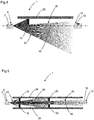
- FIG. 1 shows in the upper diagram a sensor 1 or standard sensor without diaphragms.
- the sensor 1 is, for example, a light barrier or a light grid.
- the light grid can be designed, for example, as an automation light grid or as a safety light grid.
- the light barrier can also be designed as a light barrier for automation technology or as a safe light barrier.
- Safety means machine safety in terms of safety standards such as EN 61496.
- the FIG. 1 shows an optoelectronic sensor 1, for example, a light grid or a light barrier with a transmitter 2 on one side of a monitoring path and a receiver 10 on the other side of the monitoring path.
- the light emitted from the transmitter 8 emerges as a divergent light beam 18 with a transmission cone angle or a transmission lobe 24 from the transmitter 2.
- the receiver 10 on the opposite side of the monitoring path receives all light incident within a receiving cone angle.
- the optical axis 46 is precisely aligned, so that the divergent light beam of the transmitter over-illuminates the receiver symmetrically. Is there an object between the transmitter 2 and the receiver 10, the light path is interrupted and by an evaluation unit, which the Evaluates light receiver signals, a corresponding object detection signal output.
- a plurality of transmitters are arranged on one side of a monitoring area in a first housing and a plurality of receivers on the other side of the monitoring area in a second housing.
- a transmitter always transmits light impulses in pairs to a corresponding receiver in pairs, so that ultimately not only a single line, but an area is monitored in a strip-like manner.
- the individual transmitter or receiver are arranged offset by a distance in a respective housing.
- Figure 1.1 shows the sensor 1 off FIG. 1 with at least one transmitter 2 and a first sensor optics in a first sensor housing 8 and at least one receiver 10 and a second sensor optics in a second sensor housing 12, wherein light beams 14 are emitted by the transmitter 2 and received by the receiver 10, wherein between the first Sensor housing 8 and the second sensor housing 12 and spaced from the first sensor housing 8 and spaced from the second sensor housing 12 at least one aperture 16 for limiting the light beams 14 is arranged.
- the sensor housing 8 of the transmitter 2 is tilted, for example during an adjustment or alignment of the sensor 1.
- the sensor behavior is unchanged in tilting / misalignment.
- the sensor housing 8 itself does not need to be optimally adjusted.
- the beam intensity is constant in misalignment of the sensor housing 8.
- the diaphragm 16 is, for example, an application-adapted diaphragm 16, which means that, depending on the boundary conditions, suitable diaphragms and diaphragm combinations are selected and placed in the correct position.
- diaphragm parameters can be varied:
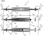
- FIG. 4 shows is in simple specular surfaces 28, a one-sided aperture 16 on the side of the reflective surface 28 is sufficient.
- FIG. 5 shows an arrangement of a first aperture 18 and multiple apertures. According to FIG. 5 for example, in high-range or mirror-surface applications or applications 28 that are very close to the optical axis 46, multiple apertures 18 and 20 must be used.
- a second aperture 20 or third aperture 22 are arranged one behind the other along the light beams.
- FIG. 6 shows a sensor 1 with mechanical barriers 48 and two apertures 16. If individual areas can be specified in the surveillance area, in which the objects 40 enter the surveillance area, these areas can easily be made mirror-safe by apertures 16. The remaining non-mirror-safe areas must then z. B. be secured by mechanical barriers 48. FIG. 6 shows such an application.
- the mirror-safe areas 30 are marked with arrows. An object 40 in the area 30 of the monitored area is reliably detected despite the mirroring. This case is shown in the middle of the picture. An object 40 in the area 32 of the surveillance area is reflected and not recognized. This is shown in the lower part of the figure.
- Figure 6.1 shows a transmitter 2 of a sensor 1 with a diaphragm 16, which has a reflective film 50. Does the transmitter 2 in the visible spectral range, the Alignment of the transmitter 2 are facilitated by the use of retroreflective surfaces or the reflective film 50 on the aperture 16. In this case, a reflection from the reflection foil 50 is evaluated with the naked eye, shown here as an observation eye.
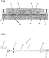
- FIG. 7 Figure 1 shows an application, namely a door entry system 36 at a platform 38.
- Such door entry systems 36 protect people waiting in front of the entering train or rail vehicle 34.
- Door access systems 36 whose doors are closed when entering the train prevent people from intentionally or accidentally get on the tracks. When the train retracts, the doors of the door access system 36 open and the passengers can board the train.
- the doors of the door access system 36 are at the same distances as the train doors.
- Along the optical axis of the intended light barrier or the light grid there are several doors that are secured by the light barrier or the light grid at the same time.
- FIG. 8 shows a sensor for securing a door access system of a platform with multiple doors with at least one transmitter 2 and a first sensor optics in a first sensor housing 8 and at least one receiver and a second sensor optics in a second sensor housing 12, wherein light beams 14 are emitted from the transmitter 2 and are received by the receiver 10, wherein between the first sensor housing 8 and the second sensor housing 12 and spaced from the first sensor housing 8 and spaced from the second sensor housing 12 at least one aperture 16 is arranged on the door access system for limiting the light beams.
- apertures 16 are particularly useful at long distances with fixed reflective surfaces in the immediate vicinity of the optical axis. These conditions can be found in the gap monitoring at platform edges with door access systems 36 on platforms 38 or generally in the corridor monitoring with reflections on glass doors.
- the gap 42 between the door access system 36 and the train or rail vehicle 34 is monitored by the sensors.
- FIG. 7 and FIG. 8 shows the basic structure.
- the according to FIG. 9 shown application or application is usually in the outdoor or outdoor area.
- the housing The sensor is designed to prevent direct rain or snow fogging and icing of the optical surfaces due to sufficient housing overhang.
- direct sunlight on the receiver 10 of the optical sensor 1 often leads to loss of availability.
- the direct sunlight can be very effectively prevented by the aperture 16, as in FIG. 9 is shown.
- fogging of the optical surfaces by condensing air humidity can be avoided.
Description
Die Erfindung betrifft einen Sensor, insbesondere einen optoelektronischen Sensor, insbesondere eine Lichtschranke nach dem Oberbegriff des Anspruchs 1.The invention relates to a sensor, in particular an optoelectronic sensor, in particular a light barrier according to the preamble of
Sensoren bzw. Lichtgitter werden in großem Umfang für die Erkennung und Vermessung von Gegenständen auf Förderbahnen, zur Gepäckkontrolle auf Förderbändern, zur Türsteuerung in Aufzügen, für den Hand- oder Körperschutz bei Arbeitsmaschinen, für die Zugangskontrolle von Personen und Fahrzeugen usw. verwendet. Die Lichtgitter bestehen aus in einem leistenförmigen Gehäuse beabstandet angeordneten Sende-Einheiten und in einem leistenförmigen Gehäuse entsprechend beabstandet angeordneten Empfangs-Einheiten. Die Sende-Einheiten senden Lichtstrahlen, im Allgemeinen Infrarot-Licht, aus, welches auf die Empfangs-Einheiten auftrifft. Die Unterbrechung der Lichtstrahlen wird detektiert und ausgewertet.Sensors or light grids are widely used for the detection and measurement of objects on conveyor tracks, for checking luggage on conveyor belts, for door control in elevators, for hand or body protection in work machines, for access control of people and vehicles. The light grids consist of spaced in a strip-shaped housing arranged transmitting units and in a strip-shaped housing correspondingly spaced receiving units. The transmitting units emit light rays, generally infrared light, which impinges on the receiving units. The interruption of the light beams is detected and evaluated.
Die Sende-Einheiten und die Empfangs-Einheiten bestehen jeweils aus einem optoelektronischen Element und einem in Strahlrichtung von diesem beabstandeten optischen Funktionselement. Bei der Sende-Einheit sendet ein optoelektronischer Wandler Licht aus, welches durch das optische Funktionselement, beispielsweise eine Linse, auf die entsprechende Empfangs-Einheit gebündelt wird. Die Empfangs-Einheit weist ein entsprechendes optisches Funktionselement auf, welches das Licht auf einem optoelektronischen Wandler sammelt.The transmitting units and the receiving units each consist of an optoelectronic element and an optical function element spaced apart in the beam direction. In the transmitting unit, an optoelectronic converter emits light, which is bundled by the optical functional element, for example a lens, onto the corresponding receiving unit. The receiving unit has a corresponding optical functional element which collects the light on an optoelectronic transducer.
Die bekannten optoelektronischen Sensoreinrichtungen arbeiten dabei nach dem Einwegprinzip, d. h. in einem ersten Gehäuse auf einer Seite der Überwachungsstrecke bzw. Überwachungsfläche sind ein oder mehrere Lichtsender angeordnet und auf der gegenüberliegenden Seite der Überwachungsstrecke bzw. Überwachungsfläche befinden sich in einem zweiten Gehäuse ein oder mehrere Lichtempfänger. Der bzw. die Lichtsender kommunizieren dabei nach einem genauen vorgegebenen Timing mit dem bzw. den Lichtempfängern, so dass jeweils Paare von Lichtsendern/Lichtempfängern aktiv sind.The known optoelectronic sensor devices operate according to the one-way principle, ie one or more light transmitters are arranged in a first housing on one side of the monitoring path or monitoring surface and on the opposite side of the monitoring path or monitoring surface are located in a second housing one or more light receivers. The or the In this case, light transmitters communicate with the light receiver (s) after an exactly predetermined timing, so that in each case pairs of light transmitters / light receivers are active.
Der Begriff "Licht" ist hierbei nicht auf das sichtbare Licht beschränkt. Unter dem Begriff "Licht" sind ganz allgemein jene elektromagnetischen Strahlen, also vom UV-Licht über den sichtbaren Bereich bis zum IR-Licht, zu verstehen, die üblicherweise für den Betrieb von Lichtschranken und Lichtgittern eingesetzt werden.The term "light" here is not limited to the visible light. The term "light" generally means those electromagnetic radiation, ie from UV light through the visible range to IR light, which are usually used for the operation of light barriers and light grids.
Speziell dann, wenn diese optoelektronischen Sensoreinrichtungen eine hohe Sicherheitsanforderung erfüllen müssen oder bei messenden Lichtgittern für die Automatisierungstechnik hohe Anforderungen an eine einwandfreie Erkennung gestellt werden, ist es notwendig, dass die Überwachungsaufgabe nicht durch unerwünschte Nebeneffekte außer Kraft gesetzt wird. Eine mögliche Gefahr einer derartigen unerwünschten Nebenwirkung besteht darin, dass ein merklicher Anteil des gerade aktiven Lichtstrahles eines Lichtsender-/Lichtempfänger-Paares um ein Objekt, das eigentlich durch Unterbrechung des Lichtstrahles erkannt werden sollte, den Empfänger durch Umspiegelung erreicht. Das hat dann zur Folge, dass dieses Objekt nicht erkannt wird.Especially when these optoelectronic sensor devices have to meet a high safety requirement or high demands are placed on a perfect detection of measuring light curtains for automation technology, it is necessary that the monitoring task is not overridden by unwanted side effects. One possible danger of such an unwanted side effect is that a significant portion of the currently active light beam of a light emitter / photoreceiver pair around an object, which should actually be detected by interruption of the light beam, reaches the receiver by re fl ecting. This has the consequence that this object is not recognized.
Dieses Problem besteht beispielsweise bei langen Überwachungsstrecken, wie beispielsweise an Bahnsteigen mit automatischen Türenzugangssystemen. Bei diesen Türenzugangssystemen ist der gesamte Bahnsteig parallel zum Zug durch eine Wand mit automatischen Türen abgesichert, um Personen vor dem einfahrenden Zug zu schützen. Die Türen des Türenzugangssystems weisen die gleichen Abstände auf wie die Zugtüren auf, so dass die Personen bei Stillstand des Zuges diesen betreten können.This problem exists, for example, in long surveillance routes, such as at platforms with automatic door access systems. In these door entry systems, the entire platform is secured parallel to the train by a wall with automatic doors to protect people from the incoming train. The doors of the door access system have the same distances as the train doors, so that the people can enter this when the train is at a standstill.
Der Aufwand für den Einsatz von Lichtschranken zur Absicherung und Kontrolle der Türen des Türenzugangssystems ist groß, da für jede Tür eine eigene Lichtschranke vorgesehen werden muss. Mehrere Türen mit einer einzigen Lichtschranke bis hin zur gesamten Zuglänge zu überwachen ist bisher nicht möglich, da die Lichtschranke Personen aufgrund einer Umspiegelung nicht erkennen kann.The effort for the use of light barriers to secure and control the doors of the door access system is great, since a separate light barrier must be provided for each door. To monitor several doors with a single light barrier up to the entire train length is not yet possible because the light barrier can not detect people due to a mirroring.
Um Umspiegelungen wirksam zu vermeiden, darf der Lichtsender den ausgesandten Lichtstrahl nur innerhalb eines relativ kleinen Sendekegelwinkels aussenden. Gleichermaßen darf der Lichtempfänger auch nur einen Lichtstrahl empfangen, der innerhalb eines relativ kleinen Empfangskegelwinkels auf den Empfänger auftritt. Je kleiner der Winkel ist, desto geringer ist die Umspiegelungsgefahr. Andererseits ist der Justageaufwand beim Ausrichten des Lichtsenders auf den Lichtempfänger entsprechend erschwert und wird vom Anwender nur dann akzeptiert werden, wenn die hohe Sicherheitsanforderung dies zwingend vorschreibt. In all den Anwendungsfällen, wo diese Einschränkungen hinsichtlich der Sende- und Empfangskegelwinkel von den Sicherheitsvorschriften jedoch nicht vorhanden sind, möchte der Anwender, zwecks einfacherer Justage von Lichtsender und Lichtempfänger, größere Sende- und Empfangskegelwinkel haben. Dies bedeutet letztlich, dass nach dem Stand der Technik für derartige Anwendungen alle optoelektronischen Sensoreinrichtungen in wenigstens zwei Varianten am Markt zur Verfügung stehen müssen.In order to effectively avoid reflections, the light emitter must emit the emitted light beam only within a relatively small transmission cone angle. Likewise, the light receiver is allowed to receive only one light beam which occurs within a relatively small receiving cone angle to the receiver. The smaller the angle, the lower the risk of mirroring. On the other hand, the adjustment effort when aligning the light emitter to the light receiver accordingly more difficult and will be accepted by the user only if the high security requirement mandatorily required. However, in all the applications where these limitations on transmit and receive cone angles are not met by safety regulations, the user desires to have larger transmit and receive cone angles for easier alignment of the light emitter and light receiver. This ultimately means that according to the state of the art for such applications all optoelectronic sensor devices must be available in at least two variants on the market.
Es ist bekannt bei Sensoren, dass eine Umspiegelung von Objekten zur Nichterkennung der Objekte führt. Das Licht wird dabei durch eine seitlich spiegelnde Fläche um das Objekt herum gespiegelt, wodurch eine gewünschte Lichtstrahlunterbrechung durch das Objekt nicht mehr detektiert werden kann. Folgende Lösungen sind hierzu bekannt:
- 1. Verringerung der Signalpegel bis der Signalpegel bei freiem Lichtweg wenig oberhalb der Schaltschwelle liegt: Das dann gewünschte Abschalten bei Umspiegelung setzt voraus, dass die dabei übertragene Lichtleistung signifikant kleiner ist als die Lichtleistung bei freiem Lichtweg. Diese Voraussetzung ist nur dann gegeben, wenn eine ausreichend homogene Abstrahl- und Empfangscharakteristik für alle Ausbreitungs- /Empfangsrichtungen vorliegt. Darüber hinaus muss eine ausreichende Leistungsreduktion durch die Umspiegelung erreicht werden. Dies ist bei spiegelnden Flächen, aber auch bei glatten/polierten Flächen, die unter einem flachen Winkel bestrahlt werden, nicht gegeben. Nachteilig ist auch, dass alterungs-, temperaturbedingte oder durch Verschmutzung verursachte Signalreduktion zur Abschaltung führt und damit die Verfügbarkeit des Sensors verringert wird. Insbesondere im Outdoor-Bereich ist bei Regen, Schnee und Nebel von einer hohen Signalschwankung auszugehen. In solchen Anwendungen ist ein Absenken der Signalpegel an die Schaltschwelle nicht möglich.
- 2. Begrenzung der sende- und empfangsseitigen Feldwinkel. Dies wird im Allgemeinen durch parallele Laserstrahlung erreicht. Ein störungsfreier Betrieb ist bei feldwinkelbegrenzten Sensoren nur bei exakter und dauerhafter Ausrichtung des Senders auf den Empfänger möglich. Besonders bei großen Abständen zwischen Sender und Empfänger oder in vibrationsbehafteten Applikationen kann diese Bedingung nicht erfüllt werden.
- 3. Einsatz ortsauflösender Sende- oder Empfangselemente. Diese ermöglicht die Richtungserkennung der einfallenden Strahlung, welche für direkte und umspiegelte unterschiedlich ist.
- 1. Reduction of the signal level until the signal level with free light path is slightly above the switching threshold: The then desired switch-off in the case of reflection requires that the transmitted light power is significantly smaller than the light power with free light path. This condition is only given if there is a sufficiently homogeneous emission and reception characteristic for all propagation / reception directions. In addition, a sufficient power reduction must be achieved by the mirroring. This is not the case with reflective surfaces, but also with smooth / polished surfaces, which are irradiated at a shallow angle. Another disadvantage is that aging, temperature-induced or caused by pollution signal reduction leads to shutdown and thus the availability of the sensor is reduced. Especially in the outdoor area is expected in rain, snow and fog from a high signal fluctuation. In such applications, lowering the signal levels to the switching threshold is not possible.
- 2. Limitation of the transmitting and receiving field angles. This is generally achieved by parallel laser radiation. Trouble-free operation is only possible with field-angle-limited sensors in the case of exact and permanent alignment of the transmitter with the receiver. Especially with large distances between transmitter and receiver or in vibration-prone applications, this condition can not be met.
- 3. Use of spatially resolving transmit or receive elements. This allows the directional detection of the incident radiation, which is different for direct and umspiegelte.
Erfahrungsgemäß gibt es nur sehr wenige Applikationen bzw. Anwendungen, bei welchen Spiegelungseffekte die Gefahr des Nichterkennens bergen. Aus diesem Grund ist die genannte technische Lösung mittels ortsauflösender Sende- oder Empfangselemente wirtschaftlich nicht sinnvoll. Die Lösungen 1 und 2 sind zwar wirtschaftlich umsetzbar, die unzureichende Verfügbarkeit verhindert aber häufig den Einsatz solcher Lösungen.Experience has shown that there are very few applications or applications in which mirroring effects involve the risk of non-recognition. For this reason, the technical solution mentioned by means of spatially resolving transmitting or receiving elements economically not useful. Although
Aus der
Aus der
Die
Die Aufgabe der vorliegenden Erfindung liegt darin, einen Sensor, insbesondere ein Lichtgitter einzusetzen, wobei spiegelnde Flächen in der Umgebung der Lichtstrahlen des Sensors existieren, ohne dass die spiegelnden Flächen die Funktion des Sensors bzw. Lichtgitters beeinträchtigen. Insbesondere ist es Aufgabe, einen Sensor zur Absicherung eines Türenzugangssystems eines Bahnsteigs bereitzustellen, wobei mit einem einzigen Sensor mehrerer Türen des Türenzugangssystems abgesichert werden können.The object of the present invention is to use a sensor, in particular a light grid, wherein reflective surfaces exist in the vicinity of the light beams of the sensor, without the reflecting surfaces impairing the function of the sensor or light grid. In particular, it is an object to provide a sensor for securing a door access system of a platform, which can be secured with a single sensor of several doors of the door access system.
Die Aufgabe wird gemäß Anspruch 1 gelöst.The problem is solved according to
Durch diesen Abstand a der Blende wird die Blende optimal positioniert, abhängig von dem Abstand H der optischen Achse zur reflektierenden Fläche, der halben Öffnung h der Sensoroptik und dem halben Öffnungswinkel α des Sensors.By this distance a of the aperture, the aperture is optimally positioned, depending on the distance H of the optical axis to the reflective surface, the half opening h of the sensor optics and half the opening angle α of the sensor.
Sind geometrische Rahmenbedingungen einer Applikation bzw. Anwendung eines Türenzugangssystems bekannt, welche die Gefahr des Nichterkennens durch eine Umspiegelung bzw. Spiegelumlenkung birgt, wird durch geeignete Positionierung der Blende bzw. der angepassten mechanischen Blende in Kombination mit dem Sensor bzw. einem Standardsensor eine zuverlässige Objektdetektion erreicht. Dabei ist entscheidend, dass weder die maximale Reichweite des Systems reduziert wird, noch die Anforderungen an die Ausrichtung des Senders oder Empfängers steigen.If geometrical basic conditions of an application or application of a door access system are known, which involves the risk of not recognizing by mirroring or mirror deflection, reliable object detection is achieved by suitably positioning the diaphragm or the adapted mechanical diaphragm in combination with the sensor or a standard sensor , It is crucial that neither the maximum range of the system is reduced, nor increase the requirements for the orientation of the transmitter or receiver.
Durch den Einsatz der Blende, bzw einer applikationsangepassten oder anwendungsangepassten Blende zur Vermeidung von Umspiegelungen wird gleichzeitig eine verbesserte Verfügbarkeit gewährleistet.The use of the aperture, or an application-adapted or application-adapted aperture to avoid reflections, at the same time ensures improved availability.
Gemäß der Erfindung ist die Blende nämlich nicht an dem Sensor befestigt, sondern beabstandet und räumlich getrennt von dem Sensorgehäuse angeordnet. Beispielsweise ist die Blende an unabhängigen Montaghalterungen bzw. an einer anderen Stelle als der Sensor angeordnet. Wird beispielsweise der Sensor ausgerichtet und justiert, wirkt sich diese Ausrichtung und Justage nicht auf die getrennte Blende aus.Namely, according to the invention, the diaphragm is not fixed to the sensor but is spaced and spatially separated from the sensor housing. For example, the diaphragm is arranged on independent mounting brackets or at a location other than the sensor. For example, if the sensor is aligned and adjusted, this alignment and adjustment will not affect the separate aperture.
Vielmehr wird die Strahlrichtung durch die lichtstrahlbegrenzende Blende und deren Position bestimmt. Erfindungsgemäß ist die Blende nicht konstruktiv mit dem Sensor verbunden. Bei dem Sensor kann es sich beispielsweise um eine Lichtschranke mit einem Sender und einem Empfänger handeln.Rather, the beam direction is determined by the light beam limiting aperture and its position. According to the invention, the diaphragm is not structurally connected to the sensor. The sensor may be, for example, a light barrier with a transmitter and a receiver.
Gemäß der Erfindung ist die Blende nur auf einer Seite einer optischen Achse zwischen Sender und Empfänger angeordnet ist, wobei die Lichtstrahlen auf einer Seite der optischen Achse durch die Blende begrenzt werden und auf der gegenüberliegenden Seite nicht begrenzt werden. Die erfindungsgemäße Wirkung der Blende wird dadurch nur auf eine Seite wirkungsvoll, beispielsweise bei einer spiegelnden Wand an der der Sensor angeordnet ist entlang der Lichtstrahlen. Eine solche Anwendung findet sich bei Türenzugangssystemen entlang von U-Bahnhöfen, durch welche die Passanten vor dem einfahrenden Zug geschützt werden. An diesen Türenzugangssystemen sind beispielsweise Sensoren angeordnet, um vor dem Schließen der Türen der Türenzugangssysteme zu prüfen, ob sich noch Personen in den Türen befinden. Um eine Umspiegelung wirksam zu unterdrücken, ist an dem Türenzugangssystem mindestens eine Blende angeordnet.According to the invention, the diaphragm is arranged only on one side of an optical axis between transmitter and receiver, wherein the light beams are limited on one side of the optical axis through the diaphragm and are not limited on the opposite side. The effect of the diaphragm according to the invention is thereby effective only on one side, for example in the case of a reflecting wall on which the sensor is arranged along the light beams. Such an application is found in door access systems along subway stations, which protect passers-by from the approaching train. At these door entry systems, for example, sensors are arranged to close the doors of the door entry systems before closing to check if there are still people in the doors. In order to effectively suppress reversal, at least one aperture is arranged on the door access system.
In Weiterbildung der Erfindung sind neben einer ersten Blende eine zweite oder dritte Blende hintereinander entlang der Lichtstrahlen angeordnet. Durch diese Blenden können gemäß der Erfindung auftretende Umspiegelungen über eine große Strecke verhindert werden. Beispielsweise können bei bereits erwähnten Türenzugangssystemen große Entfernungen auftreten, wenn beispielsweise alle Türen eines kompletten Türenzugangssystems bis zu einer kompletten Zuglänge oder darüber hinaus von einer Lichtschranke über die ganze Länge überwacht werden, wenn mehrere Blenden angeordnet werden.In a further development of the invention, in addition to a first diaphragm, a second or third diaphragm is arranged behind one another along the light beams. By these diaphragms occurring in accordance with the invention can be prevented over a large distance Umspiegelungen. For example, in already mentioned door access systems, large distances may occur when, for example, all the doors of a complete door access system are monitored up to a complete train length or beyond by a photocell over its entire length when multiple panels are arranged.
In Weiterbildung der Erfindung berechnet sich der Abstand b der zweiten Blende von der Sensoroptik nach der Formel b = H +h/tan β mit β = arctan (A + 2h/2a), wobei H den Abstand der optischen Achse zur reflektierenden Fläche bezeichnet, h die halbe Öffnung der Sensoroptik bezeichnet, β den halben Öffnungswinkel nach der ersten Blende bezeichnet, A die Öffnung der ersten Blende bezeichnet und a den Abstand der ersten Blende von der Sensoroptik bezeichnet. Durch diesen Abstand b der zweiten Blende wird die Blende optimal positioniert, abhängig vom dem Abstand H der optischen Achse zur reflektierenden Fläche, der halben Öffnung h der Sensoroptik, dem halben Öffnungswinkel β nach der ersten Blende, der Öffnung A der ersten Blende und dem Abstand a der ersten Blende von der Sensoroptik.In a development of the invention, the distance b of the second diaphragm from the sensor optics is calculated according to the formula b = H + h / tan β with β = arctan (A + 2h / 2a), where H denotes the distance between the optical axis and the reflecting surface, h designates half the opening of the sensor optics, β designates half the opening angle after the first diaphragm, A denotes the opening of the first diaphragm and a denotes the distance of the first diaphragm from the sensor optics. By this distance b of the second diaphragm, the diaphragm is optimally positioned, depending on the distance H of the optical axis to the reflective surface, the half opening h of the sensor optics, half the opening angle β after the first diaphragm, the opening A of the first diaphragm and the distance a the first aperture of the sensor optics.
In Weiterbildung der Erfindung berechnet sich der Abstand c der dritten Blende von der Sensoroptik nach der Formel c = H +h/tan γ mit γ = arctan (A + 2h/2b), wobei H den Abstand der optischen Achse zur reflektierenden Fläche bezeichnet, h die halbe Öffnung der Sensoroptik bezeichnet, γ den halben Öffnungswinkel nach der zweiten Blende bezeichnet, A die Öffnung der ersten Blende bezeichnet und b den Abstand der zweiten Blende von der Sensoroptik bezeichnet. Durch diesen Abstand c der dritten Blende, wird die dritte Blende optimal positioniert, abhängig von dem Abstand H der optischen Achse zur reflektierenden Fläche, der halbe Öffnung h der Sensoroptik, dem halben Öffnungswinkel γ nach der zweiten Blende, der Öffnung A der ersten Blende und dem Abstand b der zweiten Blende von der Sensoroptik.In a further development of the invention, the distance c of the third diaphragm from the sensor optics is calculated according to the formula c = H + h / tan γ with γ = arctan (A + 2h / 2b), where H denotes the distance of the optical axis to the reflecting surface, h designates half the opening of the sensor optics, γ denotes half the opening angle after the second diaphragm, A denotes the opening of the first diaphragm and b denotes the distance of the second diaphragm from the sensor optics. Due to this distance c of the third diaphragm, the third diaphragm is optimally positioned, depending on the distance H of the optical axis to the reflective surface, the half aperture h of the sensor optics, the half aperture angle γ after the second diaphragm, the aperture A of the first diaphragm and the distance b of the second diaphragm from the sensor optics.
In Weiterbildung der Erfindung ist der Sensor zur Absicherung eines Türenzugangssystems eines Bahnsteigs mit mehreren Türen eingesetzt, wobei mindestens eine Blende an dem Türenzugangssystem zur Begrenzung der Lichtstrahlen angeordnet ist.In a development of the invention, the sensor is used for securing a door access system of a platform with a plurality of doors, wherein at least one panel is arranged on the door access system for limiting the light beams.
Zwischen dem Sender und dem Empfänger des Sensors, entlang der optischen Achse der vorgesehenen gebildeten Lichtschranke befinden sich mehrere Türen entlang des Türenzugangssystems. die durch den Sensor gleichzeitig abgesichert werden.Between the transmitter and the receiver of the sensor, along the optical axis of the intended photocell formed are several doors along the door access system. which are simultaneously secured by the sensor.
Gemäß einer besonderen Ausführung ist der Sensor durch ein Lichtgitter gebildet mit einer Mehrzahl von Sendern und/oder Empfängern in dem ersten Sensorgehäuse und einer Mehrzahl von Empfängern und/oder Sendern in dem zweiten Sensorgehäuse. Gemäß der Erfindung kann durch die mindestens eine Blende eine Umspiegelung bei einem Lichtgitter, beispielsweise einem Lichtgitter für die Automatisierungstechnik oder einem Sicherheitslichtgitter, verhindert werden.According to a particular embodiment, the sensor is formed by a light grid having a plurality of transmitters and / or receivers in the first sensor housing and a plurality of receivers and / or transmitters in the second sensor housing. According to the invention, the at least one diaphragm can be used to prevent reflection in a light grid, for example a light grid for automation technology or a safety light grid.
Die Erfindung wird nachstehend auch hinsichtlich weiterer Vorteile und Merkmale unter Bezugnahme auf die beigefügte Zeichnung anhand von Ausführungsbeispielen erläutert. Die Figuren der Zeichnung zeigen in:
Figur 1- einen Sensor, insbesondere ein Lichtgitter ohne Blende und mit Blende;
Figur 2- einen Sensor mit Blende und Mehrfachspiegelung;
- Figur 3
- einen Sensor mit langlochförmiger Blende;
Figur 4- einen Sensor mit einer Blende an einer Seite ;
- Figur 5
- einen Sensor mit zwei Blenden hintereinander;
- Figur 5.1
- einen Sensor mit drei Blenden hintereinander;
Figur 6- einen Sensor mit zwei Blenden und mechanischen Barrieren:
- Figur 6.1
- einen Sensor mit Blende und Reflexionsfolie;
- Figur 7
- ein Türenzugangssystem an einem Bahnsteig;
Figur 8- ein Türenzugangssystem an einem Bahnsteig in einer Draufsicht;
- Figur 9
- ein Sensor mit zwei Blenden bei direkter Sonneneinstrahlung;
- FIG. 1
- a sensor, in particular a light grid without aperture and with aperture;
- FIG. 2
- a sensor with aperture and multiple reflection;
- FIG. 3
- a sensor with a slot-shaped aperture;
- FIG. 4
- a sensor with a shutter on one side;
- FIG. 5
- a sensor with two panels in a row;
- Figure 5.1
- a sensor with three panels in a row;
- FIG. 6
- a sensor with two diaphragms and mechanical barriers:
- Figure 6.1
- a sensor with aperture and reflection foil;
- FIG. 7
- a door access system at a platform;
- FIG. 8
- a door entry system at a platform in a plan view;
- FIG. 9
- a sensor with two panels in direct sunlight;
In den Figuren sind gleiche Teile mit gleichen Bezugszeichen bezeichnet.In the figures, like parts are designated by like reference numerals.
Die
Bei einem Lichtgitter sind in einem ersten Gehäuse mehrere Sender auf einer Seite einer Überwachungsfläche und in einem zweiten Gehäuse mehrere Empfänger auf der anderen Seite der Überwachungsfläche angeordnet. Dabei sendet, in kurzer zeitlicher Folge abwechselnd, immer ein Sender Lichtimpulse auf einen zugehörigen Empfänger paarweise, so dass letztlich nicht nur eine einzelne Linie, sondern eine Fläche streifenförmig überwacht wird. Die einzelnen Sender bzw. Empfänger sind dabei um einen Abstand versetzt in einem jeweiligen Gehäuse angeordnet.In a light grid, a plurality of transmitters are arranged on one side of a monitoring area in a first housing and a plurality of receivers on the other side of the monitoring area in a second housing. In this case, alternately, a transmitter always transmits light impulses in pairs to a corresponding receiver in pairs, so that ultimately not only a single line, but an area is monitored in a strip-like manner. The individual transmitter or receiver are arranged offset by a distance in a respective housing.
Gemäß
Wie bereits in der
Bei der Blende 16 handelt es sich beispielsweise um eine applikationsangepasste Blende 16, was bedeutet, dass abhängig von den Randbedingungen geeignete Blenden und Blendenkombinationen gewählt und an die richtige Stelle gesetzt werden.The
Gemäß der Erfindung können folgende Blendenparameter variiert werden:According to the invention, the following diaphragm parameters can be varied:
Die Größe und Geometrie der Außenkontur der Blende 16 gemäß
Die Größe und Geometrie der Blende 16 gemäß
- Ist Position und Lage der spiegelnden Fläche 28 bekannt, kann die
Blende 16 so gestaltet werden, dass die Strahlausbreitung nur in definierter Richtung eingeschränkt wird. Damit vereinfacht sich die Ausrichtung derBlende 16.Figur 3 zeigt beispielhaft die Verwendung einesLanglochs als Blende 16. Da seitlich keine spiegelnden Flächen 28 vorhanden sind, muss die Strahlausbreitung in der seitlichen Richtung nicht eingeschränkt werden.
- If the position and position of the reflecting
surface 28 are known, thediaphragm 16 can be designed such that the beam propagation is restricted only in a defined direction. This simplifies the orientation of theaperture 16.FIG. 3 shows by way of example the use of a slot as theaperture 16. Since there are no reflectingsurfaces 28 on the side, beam propagation in the lateral direction need not be restricted.
Wie
Gemäß
Eine Umspiegelung kann verhindert werden, wenn folgende Anordnung der Blenden 18, 20 und 22 berücksichtigt wird:
- Der Abstand b der zweiten Blende 20
von der Sensoroptik 4 berechnet sich nach der Formel b = H +h/tan β, mit β = arctan (A + 2h/2a), wobei H den Abstand der optischen Achse 46 zur reflektierenden Fläche 28 bezeichnet, h die halbe Öffnung derSensoroptik 4 bezeichnet, β den halben Öffnungswinkel nach der ersten Blende 18 bezeichnet, A die Öffnung der ersten Blende 18 bezeichnet und a den Abstand der ersten Blende 18von der Sensoroptik 4 bezeichnet.
- The distance b of the
second diaphragm 20 from thesensor optics 4 is calculated according to the formula b = H + h / tan β, where β = arctan (A + 2h / 2a), where H denotes the distance of theoptical axis 46 to the reflectingsurface 28 , h denotes the half opening of thesensor optics 4, β designates half the opening angle after thefirst diaphragm 18, A denotes the opening of thefirst diaphragm 18 and a denotes the distance of thefirst diaphragm 18 from thesensor optics 4.
Weiter berechnet sich der Abstand c der dritten Blende 22 von der Sensoroptik 4 nach der Formel c = H +h/tan γ mit γ = arctan (A + 2h/2b), wobei H den Abstand der optischen Achse 46 zur reflektierenden Fläche 28 bezeichnet, h die halbe Öffnung der Sensoroptik 4 bezeichnet, γ den halben Öffnungswinkel nach der zweiten Blende 20 bezeichnet, A die Öffnung der ersten Blende 18 bezeichnet und b den Abstand der zweiten Blende 20 von der Sensoroptik 4 bezeichnet.Furthermore, the distance c of the
Der gezielte Einsatz von Blenden 16 ist besonders bei großen Distanzen mit ortsfesten spiegelnden Flächen in unmittelbarer Nähe zur optischen Achse sinnvoll. Diese Bedingungen findet man bei der Lücken-Überwachung an Bahnsteigkanten mit Türenzugangssystemen 36 auf Bahnsteigen 38 oder allgemein bei der Flurüberwachung mit Reflexionen an Glastüren. Durch die Sensoren wird die Lücke 42 zwischen Türenzugangssystem 36 und Zug bzw. Schienenfahrzeug 34 überwacht.
Die gemäß
- 11
- Sensorsensor
- 22
- Sendertransmitter
- 4, 64, 6
- Sensoroptiksensor optics
- 88th
- erstes Sensorgehäusefirst sensor housing
- 1010
- Empfängerreceiver
- 1212
- zweites Sensorgehäusesecond sensor housing
- 1414
- Lichtstrahlenlight rays
- 1616
- Blendecover
- 1818
- erste Blendefirst aperture
- 2020
- zweite Blendesecond aperture
- 2222
- dritte Blendethird aperture
- 2424
- Sendekeuletransmission lobe
- 2626
- reduzierte Sendekeulereduced transmission lobe
- 2828
- reflektierende Flächereflective surface
- 3030
- grüner Bereichgreen area
- 3232
- roter Bereichred area
- 3434
- Schienenfahrzeugtrack vehicle
- 3636
- TürenzugangssystemDoor access system
- 3838
- Bahnsteigplatform
- 4040
- Objektobject
- 4242
- Lückegap
- 4444
- SonneSun
- 4646
- optische Achseoptical axis
- 4848
- mechanische Barrieremechanical barrier
- 5050
- Reflexfoliereflective tape
- AA
- Öffnung der BlendeOpening the aperture
- hH
- halbe Öffnung der Sensoroptikhalf opening of the sensor optics
- HH
- Abstand der optischen Achse zur reflektierenden FlächeDistance of the optical axis to the reflecting surface
- αα
- halber Öffnungswinkel des Sensorshalf the opening angle of the sensor
- ββ
- halber Öffnungswinkel nach der ersten Blendehalf the opening angle after the first aperture
- γγ
- halber Öffnungswinkel nach der zweiten Blendehalf the opening angle after the second aperture
Claims (6)
- A sensor having at least one transmitter (2) and a first sensor optics (4) in a first sensor housing (8) and having at least one receiver (10) and a second sensor optics (6) in a second sensor housing (12), wherein light beams (14) are transmitted by the transmitter (2) and are received by the receiver (10), having a reflective surface (28) in parallel with the optical axis (46) of the transmitter (2) and of the receiver (10),
wherein at least one diaphragm is arranged between the first sensor housing (8) and the second sensor housing (12) and spaced apart and spatially separate from the first sensor housing (8) and spaced apart and spatially separate from the second sensor housing (12) at a different point than the sensor (16, 18) for restricting the light beams (14), characterized in that the spacing a of the diaphragm (16, 18) from the sensor optics (4, 6) is calculated according to the formula a = H - h/tan α, where H is the spacing of the optical axis (46) from the reflective surface (28), h is half the opening of the sensor optics (4, 6), and α is half the opening angle of the sensor (1), with the diaphragm only being arranged at one side of the optical axis (46) between the transmitter (2) and the receiver (10), and with the light beams (14) being restricted on one side of the optical axis (46) by the diaphragm (16, 18) and not being restricted on the oppositely disposed side. - A sensor in accordance with the preceding claim, characterized in that a second diaphragm (20) or third diaphragm (22) are arranged beside the first diaphragm (18) behind one another along the light beams (14).
- A sensor in accordance with claim 2, characterized in that the spacing b of the second diaphragm (20) from the sensor optics (4, 6) is calculated in accordance with the formula b = H + h/tan β, where β = arctan (A + 2h/2a), where H is the distance of the optical axis (46) from the reflective surface (28), h is half the opening of the sensor optics (4, 8), β is half the opening angle after the first diaphragm (18), A is the opening of the first diaphragm (18), and a is the spacing of the first diaphragm (18) from the sensor optics (4, 6).
- A sensor in accordance with one of the preceding claims 2 to 3, characterized in that the spacing c of the third diaphragm (22) from the sensor optics (4, 6) is calculated in accordance with the formula c = H + h/tan γ, where γ = arctan (A + 2h/2b), where H is the distance of the optical axis (46) from the reflective surface (28), h is half the opening of the sensor optics (4, 8), γ is half the opening angle after the second diaphragm (20), A is the opening of the first diaphragm (18), and b is the spacing of the second diaphragm (20) from the sensor optics (4, 6).
- A sensor in accordance with any one of the preceding claims for securing a door access system of a railway platform having a plurality of doors, wherein at least one diaphragm (16, 18) is arranged at the door access system to restrict the light beams (14).
- A sensor in accordance with any one of the preceding claims, characterized in that the sensor (1) is formed by a light grid having a plurality of transmitters and/or receivers in the first sensor housing, and having a plurality of receivers and/or transmitters in the second sensor housing.
Applications Claiming Priority (1)
| Application Number | Priority Date | Filing Date | Title |
|---|---|---|---|
| DE102012109973 | 2012-10-19 |
Publications (2)
| Publication Number | Publication Date |
|---|---|
| EP2722692A1 EP2722692A1 (en) | 2014-04-23 |
| EP2722692B1 true EP2722692B1 (en) | 2017-04-12 |
Family
ID=48142674
Family Applications (1)
| Application Number | Title | Priority Date | Filing Date |
|---|---|---|---|
| EP13164540.0A Active EP2722692B1 (en) | 2012-10-19 | 2013-04-19 | Sensor |
Country Status (1)
| Country | Link |
|---|---|
| EP (1) | EP2722692B1 (en) |
Families Citing this family (2)
| Publication number | Priority date | Publication date | Assignee | Title |
|---|---|---|---|---|
| DE202018105666U1 (en) * | 2018-10-02 | 2020-01-03 | Leuze Electronic Gmbh + Co. Kg | Light barrier arrangement |
| CN110077602A (en) * | 2019-05-16 | 2019-08-02 | 中国商用飞机有限责任公司 | Ice crystal detector and mixed state icing detector |
Family Cites Families (3)
| Publication number | Priority date | Publication date | Assignee | Title |
|---|---|---|---|---|
| DE10329881A1 (en) | 2003-07-02 | 2005-01-20 | Sick Ag | light Curtain |
| DE202007002078U1 (en) | 2007-02-13 | 2007-04-26 | Sick Ag | Optoelectronic sensor aperture for protecting e.g. bending press, has recess in area that is covered by front side of upper die in operating condition and having dimensions less than viewable length of tool tip in working direction of tool |
| DE102007051681A1 (en) | 2007-10-26 | 2009-04-30 | Sick Ag | Optoelectronic sensor |
-
2013
- 2013-04-19 EP EP13164540.0A patent/EP2722692B1/en active Active
Non-Patent Citations (1)
| Title |
|---|
| None * |
Also Published As
| Publication number | Publication date |
|---|---|
| EP2722692A1 (en) | 2014-04-23 |
Similar Documents
| Publication | Publication Date | Title |
|---|---|---|
| EP1089030B1 (en) | Device and method for monitoring a protection zone | |
| DE4340756C5 (en) | Laser range finding device | |
| EP2229496B1 (en) | Safety system for safeguarding a moving, guided motion element against unwanted collisions | |
| EP2362243B1 (en) | Optoelectronic sensor | |
| DE102006050189B4 (en) | Light grid with alignment light transmitter and alignment method | |
| DE102013012789A1 (en) | Scanning optoelectronic detection device and motor vehicle with such a detection device | |
| EP2226652B1 (en) | Optoelectronic sensor with alignment light transmitter | |
| EP0926646B1 (en) | Optical smoke detector | |
| EP2362242B1 (en) | Optoelectronic sensor | |
| DE10146639A1 (en) | Light grid with beam splitter | |
| EP2722692B1 (en) | Sensor | |
| EP2703837B1 (en) | Safety laser scanner | |
| EP1780559B1 (en) | Optical sensor | |
| WO2016000837A1 (en) | Arrangement for attenuating impinging light of a beam | |
| DE202008016946U1 (en) | Light curtain or photocell | |
| EP0236755A1 (en) | Device for detecting an interruption in a space between the emitter and the receiver of a light signal sent by at least one emitter | |
| DE102009009386B4 (en) | Optoelectronic device | |
| DE202006003841U1 (en) | Object detection unit for light barrier system has additional detectors for scattered radiation place outside path of direct reflection | |
| EP2312340B1 (en) | Method for operating an optoelectronic sensor and optoelectronic sensor | |
| DE19537051C1 (en) | Optoelectronic sensor arrangement | |
| EP2634598B1 (en) | Optical sensor | |
| EP2226655B1 (en) | Optoelectronic sensor | |
| DE202012103344U1 (en) | Safety light scanner | |
| EP1265205B1 (en) | Linear smoke detector | |
| DE19639403A1 (en) | Opto-electronic sensor for identification of objects during monitoring |
Legal Events
| Date | Code | Title | Description |
|---|---|---|---|
| PUAI | Public reference made under article 153(3) epc to a published international application that has entered the european phase |
Free format text: ORIGINAL CODE: 0009012 |
|
| AK | Designated contracting states |
Kind code of ref document: A1 Designated state(s): AL AT BE BG CH CY CZ DE DK EE ES FI FR GB GR HR HU IE IS IT LI LT LU LV MC MK MT NL NO PL PT RO RS SE SI SK SM TR |
|
| AX | Request for extension of the european patent |
Extension state: BA ME |
|
| REG | Reference to a national code |
Ref country code: HK Ref legal event code: DE Ref document number: 1193162 Country of ref document: HK |
|
| 17P | Request for examination filed |
Effective date: 20140829 |
|
| RBV | Designated contracting states (corrected) |
Designated state(s): AL AT BE BG CH CY CZ DE DK EE ES FI FR GB GR HR HU IE IS IT LI LT LU LV MC MK MT NL NO PL PT RO RS SE SI SK SM TR |
|
| 17Q | First examination report despatched |
Effective date: 20150327 |
|
| GRAP | Despatch of communication of intention to grant a patent |
Free format text: ORIGINAL CODE: EPIDOSNIGR1 |
|
| GRAJ | Information related to disapproval of communication of intention to grant by the applicant or resumption of examination proceedings by the epo deleted |
Free format text: ORIGINAL CODE: EPIDOSDIGR1 |
|
| INTG | Intention to grant announced |
Effective date: 20161116 |
|
| GRAP | Despatch of communication of intention to grant a patent |
Free format text: ORIGINAL CODE: EPIDOSNIGR1 |
|
| INTC | Intention to grant announced (deleted) | ||
| INTG | Intention to grant announced |
Effective date: 20170104 |
|
| GRAS | Grant fee paid |
Free format text: ORIGINAL CODE: EPIDOSNIGR3 |
|
| GRAA | (expected) grant |
Free format text: ORIGINAL CODE: 0009210 |
|
| AK | Designated contracting states |
Kind code of ref document: B1 Designated state(s): AL AT BE BG CH CY CZ DE DK EE ES FI FR GB GR HR HU IE IS IT LI LT LU LV MC MK MT NL NO PL PT RO RS SE SI SK SM TR |
|
| REG | Reference to a national code |
Ref country code: GB Ref legal event code: FG4D Free format text: NOT ENGLISH |
|
| REG | Reference to a national code |
Ref country code: CH Ref legal event code: EP |
|
| REG | Reference to a national code |
Ref country code: IE Ref legal event code: FG4D Free format text: LANGUAGE OF EP DOCUMENT: GERMAN |
|
| REG | Reference to a national code |
Ref country code: AT Ref legal event code: REF Ref document number: 884451 Country of ref document: AT Kind code of ref document: T Effective date: 20170515 |
|
| REG | Reference to a national code |
Ref country code: DE Ref legal event code: R096 Ref document number: 502013006912 Country of ref document: DE |
|
| REG | Reference to a national code |
Ref country code: FR Ref legal event code: PLFP Year of fee payment: 5 |
|
| REG | Reference to a national code |
Ref country code: NL Ref legal event code: MP Effective date: 20170412 |
|
| REG | Reference to a national code |
Ref country code: LT Ref legal event code: MG4D |
|
| PG25 | Lapsed in a contracting state [announced via postgrant information from national office to epo] |
Ref country code: NL Free format text: LAPSE BECAUSE OF FAILURE TO SUBMIT A TRANSLATION OF THE DESCRIPTION OR TO PAY THE FEE WITHIN THE PRESCRIBED TIME-LIMIT Effective date: 20170412 |
|
| PG25 | Lapsed in a contracting state [announced via postgrant information from national office to epo] |
Ref country code: LT Free format text: LAPSE BECAUSE OF FAILURE TO SUBMIT A TRANSLATION OF THE DESCRIPTION OR TO PAY THE FEE WITHIN THE PRESCRIBED TIME-LIMIT Effective date: 20170412 Ref country code: GR Free format text: LAPSE BECAUSE OF FAILURE TO SUBMIT A TRANSLATION OF THE DESCRIPTION OR TO PAY THE FEE WITHIN THE PRESCRIBED TIME-LIMIT Effective date: 20170713 Ref country code: ES Free format text: LAPSE BECAUSE OF FAILURE TO SUBMIT A TRANSLATION OF THE DESCRIPTION OR TO PAY THE FEE WITHIN THE PRESCRIBED TIME-LIMIT Effective date: 20170412 Ref country code: NO Free format text: LAPSE BECAUSE OF FAILURE TO SUBMIT A TRANSLATION OF THE DESCRIPTION OR TO PAY THE FEE WITHIN THE PRESCRIBED TIME-LIMIT Effective date: 20170712 Ref country code: HR Free format text: LAPSE BECAUSE OF FAILURE TO SUBMIT A TRANSLATION OF THE DESCRIPTION OR TO PAY THE FEE WITHIN THE PRESCRIBED TIME-LIMIT Effective date: 20170412 Ref country code: FI Free format text: LAPSE BECAUSE OF FAILURE TO SUBMIT A TRANSLATION OF THE DESCRIPTION OR TO PAY THE FEE WITHIN THE PRESCRIBED TIME-LIMIT Effective date: 20170412 |
|
| PG25 | Lapsed in a contracting state [announced via postgrant information from national office to epo] |
Ref country code: PL Free format text: LAPSE BECAUSE OF FAILURE TO SUBMIT A TRANSLATION OF THE DESCRIPTION OR TO PAY THE FEE WITHIN THE PRESCRIBED TIME-LIMIT Effective date: 20170412 Ref country code: RS Free format text: LAPSE BECAUSE OF FAILURE TO SUBMIT A TRANSLATION OF THE DESCRIPTION OR TO PAY THE FEE WITHIN THE PRESCRIBED TIME-LIMIT Effective date: 20170412 Ref country code: SE Free format text: LAPSE BECAUSE OF FAILURE TO SUBMIT A TRANSLATION OF THE DESCRIPTION OR TO PAY THE FEE WITHIN THE PRESCRIBED TIME-LIMIT Effective date: 20170412 Ref country code: BG Free format text: LAPSE BECAUSE OF FAILURE TO SUBMIT A TRANSLATION OF THE DESCRIPTION OR TO PAY THE FEE WITHIN THE PRESCRIBED TIME-LIMIT Effective date: 20170712 Ref country code: IS Free format text: LAPSE BECAUSE OF FAILURE TO SUBMIT A TRANSLATION OF THE DESCRIPTION OR TO PAY THE FEE WITHIN THE PRESCRIBED TIME-LIMIT Effective date: 20170812 Ref country code: LV Free format text: LAPSE BECAUSE OF FAILURE TO SUBMIT A TRANSLATION OF THE DESCRIPTION OR TO PAY THE FEE WITHIN THE PRESCRIBED TIME-LIMIT Effective date: 20170412 |
|
| REG | Reference to a national code |
Ref country code: DE Ref legal event code: R097 Ref document number: 502013006912 Country of ref document: DE |
|
| REG | Reference to a national code |
Ref country code: IE Ref legal event code: MM4A |
|
| PG25 | Lapsed in a contracting state [announced via postgrant information from national office to epo] |
Ref country code: RO Free format text: LAPSE BECAUSE OF FAILURE TO SUBMIT A TRANSLATION OF THE DESCRIPTION OR TO PAY THE FEE WITHIN THE PRESCRIBED TIME-LIMIT Effective date: 20170412 Ref country code: EE Free format text: LAPSE BECAUSE OF FAILURE TO SUBMIT A TRANSLATION OF THE DESCRIPTION OR TO PAY THE FEE WITHIN THE PRESCRIBED TIME-LIMIT Effective date: 20170412 Ref country code: DK Free format text: LAPSE BECAUSE OF FAILURE TO SUBMIT A TRANSLATION OF THE DESCRIPTION OR TO PAY THE FEE WITHIN THE PRESCRIBED TIME-LIMIT Effective date: 20170412 Ref country code: SK Free format text: LAPSE BECAUSE OF FAILURE TO SUBMIT A TRANSLATION OF THE DESCRIPTION OR TO PAY THE FEE WITHIN THE PRESCRIBED TIME-LIMIT Effective date: 20170412 Ref country code: MC Free format text: LAPSE BECAUSE OF FAILURE TO SUBMIT A TRANSLATION OF THE DESCRIPTION OR TO PAY THE FEE WITHIN THE PRESCRIBED TIME-LIMIT Effective date: 20170412 Ref country code: CZ Free format text: LAPSE BECAUSE OF FAILURE TO SUBMIT A TRANSLATION OF THE DESCRIPTION OR TO PAY THE FEE WITHIN THE PRESCRIBED TIME-LIMIT Effective date: 20170412 |
|
| REG | Reference to a national code |
Ref country code: HK Ref legal event code: GR Ref document number: 1193162 Country of ref document: HK |
|
| PLBE | No opposition filed within time limit |
Free format text: ORIGINAL CODE: 0009261 |
|
| STAA | Information on the status of an ep patent application or granted ep patent |
Free format text: STATUS: NO OPPOSITION FILED WITHIN TIME LIMIT |
|
| PG25 | Lapsed in a contracting state [announced via postgrant information from national office to epo] |
Ref country code: IT Free format text: LAPSE BECAUSE OF FAILURE TO SUBMIT A TRANSLATION OF THE DESCRIPTION OR TO PAY THE FEE WITHIN THE PRESCRIBED TIME-LIMIT Effective date: 20170412 Ref country code: LU Free format text: LAPSE BECAUSE OF NON-PAYMENT OF DUE FEES Effective date: 20170419 Ref country code: SM Free format text: LAPSE BECAUSE OF FAILURE TO SUBMIT A TRANSLATION OF THE DESCRIPTION OR TO PAY THE FEE WITHIN THE PRESCRIBED TIME-LIMIT Effective date: 20170412 |
|
| 26N | No opposition filed |
Effective date: 20180115 |
|
| REG | Reference to a national code |
Ref country code: BE Ref legal event code: MM Effective date: 20170430 |
|
| REG | Reference to a national code |
Ref country code: FR Ref legal event code: PLFP Year of fee payment: 6 |
|
| PG25 | Lapsed in a contracting state [announced via postgrant information from national office to epo] |
Ref country code: IE Free format text: LAPSE BECAUSE OF NON-PAYMENT OF DUE FEES Effective date: 20170419 |
|
| PG25 | Lapsed in a contracting state [announced via postgrant information from national office to epo] |
Ref country code: BE Free format text: LAPSE BECAUSE OF NON-PAYMENT OF DUE FEES Effective date: 20170430 Ref country code: SI Free format text: LAPSE BECAUSE OF FAILURE TO SUBMIT A TRANSLATION OF THE DESCRIPTION OR TO PAY THE FEE WITHIN THE PRESCRIBED TIME-LIMIT Effective date: 20170412 |
|
| PG25 | Lapsed in a contracting state [announced via postgrant information from national office to epo] |
Ref country code: MT Free format text: LAPSE BECAUSE OF FAILURE TO SUBMIT A TRANSLATION OF THE DESCRIPTION OR TO PAY THE FEE WITHIN THE PRESCRIBED TIME-LIMIT Effective date: 20170412 |
|
| REG | Reference to a national code |
Ref country code: AT Ref legal event code: MM01 Ref document number: 884451 Country of ref document: AT Kind code of ref document: T Effective date: 20180419 |
|
| PG25 | Lapsed in a contracting state [announced via postgrant information from national office to epo] |
Ref country code: HU Free format text: LAPSE BECAUSE OF FAILURE TO SUBMIT A TRANSLATION OF THE DESCRIPTION OR TO PAY THE FEE WITHIN THE PRESCRIBED TIME-LIMIT; INVALID AB INITIO Effective date: 20130419 |
|
| PG25 | Lapsed in a contracting state [announced via postgrant information from national office to epo] |
Ref country code: AT Free format text: LAPSE BECAUSE OF NON-PAYMENT OF DUE FEES Effective date: 20180419 Ref country code: CY Free format text: LAPSE BECAUSE OF NON-PAYMENT OF DUE FEES Effective date: 20170412 |
|
| PG25 | Lapsed in a contracting state [announced via postgrant information from national office to epo] |
Ref country code: MK Free format text: LAPSE BECAUSE OF FAILURE TO SUBMIT A TRANSLATION OF THE DESCRIPTION OR TO PAY THE FEE WITHIN THE PRESCRIBED TIME-LIMIT Effective date: 20170412 |
|
| PG25 | Lapsed in a contracting state [announced via postgrant information from national office to epo] |
Ref country code: TR Free format text: LAPSE BECAUSE OF FAILURE TO SUBMIT A TRANSLATION OF THE DESCRIPTION OR TO PAY THE FEE WITHIN THE PRESCRIBED TIME-LIMIT Effective date: 20170412 |
|
| PG25 | Lapsed in a contracting state [announced via postgrant information from national office to epo] |
Ref country code: PT Free format text: LAPSE BECAUSE OF FAILURE TO SUBMIT A TRANSLATION OF THE DESCRIPTION OR TO PAY THE FEE WITHIN THE PRESCRIBED TIME-LIMIT Effective date: 20170412 |
|
| PG25 | Lapsed in a contracting state [announced via postgrant information from national office to epo] |
Ref country code: AL Free format text: LAPSE BECAUSE OF FAILURE TO SUBMIT A TRANSLATION OF THE DESCRIPTION OR TO PAY THE FEE WITHIN THE PRESCRIBED TIME-LIMIT Effective date: 20170412 |
|
| PGFP | Annual fee paid to national office [announced via postgrant information from national office to epo] |
Ref country code: FR Payment date: 20230417 Year of fee payment: 11 Ref country code: DE Payment date: 20230418 Year of fee payment: 11 Ref country code: CH Payment date: 20230502 Year of fee payment: 11 |
|
| PGFP | Annual fee paid to national office [announced via postgrant information from national office to epo] |
Ref country code: GB Payment date: 20230413 Year of fee payment: 11 |