EP2722692B1 - Capteur - Google Patents
Capteur Download PDFInfo
- Publication number
- EP2722692B1 EP2722692B1 EP13164540.0A EP13164540A EP2722692B1 EP 2722692 B1 EP2722692 B1 EP 2722692B1 EP 13164540 A EP13164540 A EP 13164540A EP 2722692 B1 EP2722692 B1 EP 2722692B1
- Authority
- EP
- European Patent Office
- Prior art keywords
- sensor
- diaphragm
- light
- optics
- receiver
- Prior art date
- Legal status (The legal status is an assumption and is not a legal conclusion. Google has not performed a legal analysis and makes no representation as to the accuracy of the status listed.)
- Active
Links
- 230000003287 optical effect Effects 0.000 claims description 30
- 230000004888 barrier function Effects 0.000 description 18
- 238000012544 monitoring process Methods 0.000 description 12
- 230000005693 optoelectronics Effects 0.000 description 9
- 230000005540 biological transmission Effects 0.000 description 6
- 238000001514 detection method Methods 0.000 description 5
- 206010052128 Glare Diseases 0.000 description 4
- 230000018109 developmental process Effects 0.000 description 4
- 230000000694 effects Effects 0.000 description 4
- 238000005516 engineering process Methods 0.000 description 3
- 239000011888 foil Substances 0.000 description 2
- 230000005855 radiation Effects 0.000 description 2
- 241001136792 Alle Species 0.000 description 1
- 240000003517 Elaeocarpus dentatus Species 0.000 description 1
- 230000032683 aging Effects 0.000 description 1
- 238000004378 air conditioning Methods 0.000 description 1
- 238000010586 diagram Methods 0.000 description 1
- 230000005670 electromagnetic radiation Effects 0.000 description 1
- 238000011156 evaluation Methods 0.000 description 1
- 239000011521 glass Substances 0.000 description 1
- 238000005259 measurement Methods 0.000 description 1
- 230000003595 spectral effect Effects 0.000 description 1
Images


Classifications
-
- G—PHYSICS
- G01—MEASURING; TESTING
- G01V—GEOPHYSICS; GRAVITATIONAL MEASUREMENTS; DETECTING MASSES OR OBJECTS; TAGS
- G01V8/00—Prospecting or detecting by optical means
- G01V8/10—Detecting, e.g. by using light barriers
Definitions
- the invention relates to a sensor, in particular an optoelectronic sensor, in particular a light barrier according to the preamble of claim 1.
- Sensors or light grids are widely used for the detection and measurement of objects on conveyor tracks, for checking luggage on conveyor belts, for door control in elevators, for hand or body protection in work machines, for access control of people and vehicles.
- the light grids consist of spaced in a strip-shaped housing arranged transmitting units and in a strip-shaped housing correspondingly spaced receiving units.
- the transmitting units emit light rays, generally infrared light, which impinges on the receiving units. The interruption of the light beams is detected and evaluated.
- the transmitting units and the receiving units each consist of an optoelectronic element and an optical function element spaced apart in the beam direction.
- an optoelectronic converter emits light, which is bundled by the optical functional element, for example a lens, onto the corresponding receiving unit.
- the receiving unit has a corresponding optical functional element which collects the light on an optoelectronic transducer.
- the known optoelectronic sensor devices operate according to the one-way principle, ie one or more light transmitters are arranged in a first housing on one side of the monitoring path or monitoring surface and on the opposite side of the monitoring path or monitoring surface are located in a second housing one or more light receivers.
- the or the In this case, light transmitters communicate with the light receiver (s) after an exactly predetermined timing, so that in each case pairs of light transmitters / light receivers are active.
- light here is not limited to the visible light.
- the term “light” generally means those electromagnetic radiation, ie from UV light through the visible range to IR light, which are usually used for the operation of light barriers and light grids.
- the light emitter In order to effectively avoid reflections, the light emitter must emit the emitted light beam only within a relatively small transmission cone angle. Likewise, the light receiver is allowed to receive only one light beam which occurs within a relatively small receiving cone angle to the receiver. The smaller the angle, the lower the risk of mirroring. On the other hand, the adjustment effort when aligning the light emitter to the light receiver accordingly more difficult and will be accepted by the user only if the high security requirement mandatorily required. However, in all the applications where these limitations on transmit and receive cone angles are not met by safety regulations, the user desires to have larger transmit and receive cone angles for easier alignment of the light emitter and light receiver. This ultimately means that according to the state of the art for such applications all optoelectronic sensor devices must be available in at least two variants on the market.
- From the DE 103 29 881 A1 is a light grid known with a slit to limit emitted light rays.
- From the DE 10 2007 051 681 A1 is a light grid with a multilochrome known to limit the transmission and / or the receiving cone angle.
- the DE 20 2007 002 078 U1 discloses a shutter for an optoelectronic sensor, wherein the shutter is disposed between a light receiver, a sensor consisting of light emitter and light receiver and an end face of an upper tool of a press.
- the aperture can be integrated in the light receiver.
- the object of the present invention is to use a sensor, in particular a light grid, wherein reflective surfaces exist in the vicinity of the light beams of the sensor, without the reflecting surfaces impairing the function of the sensor or light grid.
- a sensor for securing a door access system of a platform, which can be secured with a single sensor of several doors of the door access system.
- the aperture is optimally positioned, depending on the distance H of the optical axis to the reflective surface, the half opening h of the sensor optics and half the opening angle ⁇ of the sensor.
- the diaphragm is not fixed to the sensor but is spaced and spatially separated from the sensor housing.
- the diaphragm is arranged on independent mounting brackets or at a location other than the sensor. For example, if the sensor is aligned and adjusted, this alignment and adjustment will not affect the separate aperture.
- the beam direction is determined by the light beam limiting aperture and its position.
- the diaphragm is not structurally connected to the sensor.
- the sensor may be, for example, a light barrier with a transmitter and a receiver.
- the diaphragm is arranged only on one side of an optical axis between transmitter and receiver, wherein the light beams are limited on one side of the optical axis through the diaphragm and are not limited on the opposite side.
- the effect of the diaphragm according to the invention is thereby effective only on one side, for example in the case of a reflecting wall on which the sensor is arranged along the light beams.
- a reflecting wall on which the sensor is arranged along the light beams Such an application is found in door access systems along subway stations, which protect passers-by from the approaching train.
- sensors are arranged to close the doors of the door entry systems before closing to check if there are still people in the doors.
- at least one aperture is arranged on the door access system.
- a second or third diaphragm is arranged behind one another along the light beams.
- the diaphragm is optimally positioned, depending on the distance H of the optical axis to the reflective surface, the half opening h of the sensor optics, half the opening angle ⁇ after the first diaphragm, the opening A of the first diaphragm and the distance a the first aperture of the sensor optics.
- the third diaphragm is optimally positioned, depending on the distance H of the optical axis to the reflective surface, the half aperture h of the sensor optics, the half aperture angle ⁇ after the second diaphragm, the aperture A of the first diaphragm and the distance b of the second diaphragm from the sensor optics.
- the senor is used for securing a door access system of a platform with a plurality of doors, wherein at least one panel is arranged on the door access system for limiting the light beams.
- the senor is formed by a light grid having a plurality of transmitters and / or receivers in the first sensor housing and a plurality of receivers and / or transmitters in the second sensor housing.
- the at least one diaphragm can be used to prevent reflection in a light grid, for example a light grid for automation technology or a safety light grid.
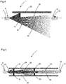
- FIG. 1 shows in the upper diagram a sensor 1 or standard sensor without diaphragms.
- the sensor 1 is, for example, a light barrier or a light grid.
- the light grid can be designed, for example, as an automation light grid or as a safety light grid.
- the light barrier can also be designed as a light barrier for automation technology or as a safe light barrier.
- Safety means machine safety in terms of safety standards such as EN 61496.
- the FIG. 1 shows an optoelectronic sensor 1, for example, a light grid or a light barrier with a transmitter 2 on one side of a monitoring path and a receiver 10 on the other side of the monitoring path.
- the light emitted from the transmitter 8 emerges as a divergent light beam 18 with a transmission cone angle or a transmission lobe 24 from the transmitter 2.
- the receiver 10 on the opposite side of the monitoring path receives all light incident within a receiving cone angle.
- the optical axis 46 is precisely aligned, so that the divergent light beam of the transmitter over-illuminates the receiver symmetrically. Is there an object between the transmitter 2 and the receiver 10, the light path is interrupted and by an evaluation unit, which the Evaluates light receiver signals, a corresponding object detection signal output.
- a plurality of transmitters are arranged on one side of a monitoring area in a first housing and a plurality of receivers on the other side of the monitoring area in a second housing.
- a transmitter always transmits light impulses in pairs to a corresponding receiver in pairs, so that ultimately not only a single line, but an area is monitored in a strip-like manner.
- the individual transmitter or receiver are arranged offset by a distance in a respective housing.
- Figure 1.1 shows the sensor 1 off FIG. 1 with at least one transmitter 2 and a first sensor optics in a first sensor housing 8 and at least one receiver 10 and a second sensor optics in a second sensor housing 12, wherein light beams 14 are emitted by the transmitter 2 and received by the receiver 10, wherein between the first Sensor housing 8 and the second sensor housing 12 and spaced from the first sensor housing 8 and spaced from the second sensor housing 12 at least one aperture 16 for limiting the light beams 14 is arranged.
- the sensor housing 8 of the transmitter 2 is tilted, for example during an adjustment or alignment of the sensor 1.
- the sensor behavior is unchanged in tilting / misalignment.
- the sensor housing 8 itself does not need to be optimally adjusted.
- the beam intensity is constant in misalignment of the sensor housing 8.
- the diaphragm 16 is, for example, an application-adapted diaphragm 16, which means that, depending on the boundary conditions, suitable diaphragms and diaphragm combinations are selected and placed in the correct position.
- diaphragm parameters can be varied:
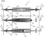
- FIG. 4 shows is in simple specular surfaces 28, a one-sided aperture 16 on the side of the reflective surface 28 is sufficient.
- FIG. 5 shows an arrangement of a first aperture 18 and multiple apertures. According to FIG. 5 for example, in high-range or mirror-surface applications or applications 28 that are very close to the optical axis 46, multiple apertures 18 and 20 must be used.
- a second aperture 20 or third aperture 22 are arranged one behind the other along the light beams.
- FIG. 6 shows a sensor 1 with mechanical barriers 48 and two apertures 16. If individual areas can be specified in the surveillance area, in which the objects 40 enter the surveillance area, these areas can easily be made mirror-safe by apertures 16. The remaining non-mirror-safe areas must then z. B. be secured by mechanical barriers 48. FIG. 6 shows such an application.
- the mirror-safe areas 30 are marked with arrows. An object 40 in the area 30 of the monitored area is reliably detected despite the mirroring. This case is shown in the middle of the picture. An object 40 in the area 32 of the surveillance area is reflected and not recognized. This is shown in the lower part of the figure.
- Figure 6.1 shows a transmitter 2 of a sensor 1 with a diaphragm 16, which has a reflective film 50. Does the transmitter 2 in the visible spectral range, the Alignment of the transmitter 2 are facilitated by the use of retroreflective surfaces or the reflective film 50 on the aperture 16. In this case, a reflection from the reflection foil 50 is evaluated with the naked eye, shown here as an observation eye.
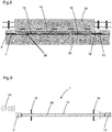
- FIG. 7 Figure 1 shows an application, namely a door entry system 36 at a platform 38.
- Such door entry systems 36 protect people waiting in front of the entering train or rail vehicle 34.
- Door access systems 36 whose doors are closed when entering the train prevent people from intentionally or accidentally get on the tracks. When the train retracts, the doors of the door access system 36 open and the passengers can board the train.
- the doors of the door access system 36 are at the same distances as the train doors.
- Along the optical axis of the intended light barrier or the light grid there are several doors that are secured by the light barrier or the light grid at the same time.
- FIG. 8 shows a sensor for securing a door access system of a platform with multiple doors with at least one transmitter 2 and a first sensor optics in a first sensor housing 8 and at least one receiver and a second sensor optics in a second sensor housing 12, wherein light beams 14 are emitted from the transmitter 2 and are received by the receiver 10, wherein between the first sensor housing 8 and the second sensor housing 12 and spaced from the first sensor housing 8 and spaced from the second sensor housing 12 at least one aperture 16 is arranged on the door access system for limiting the light beams.
- apertures 16 are particularly useful at long distances with fixed reflective surfaces in the immediate vicinity of the optical axis. These conditions can be found in the gap monitoring at platform edges with door access systems 36 on platforms 38 or generally in the corridor monitoring with reflections on glass doors.
- the gap 42 between the door access system 36 and the train or rail vehicle 34 is monitored by the sensors.
- FIG. 7 and FIG. 8 shows the basic structure.
- the according to FIG. 9 shown application or application is usually in the outdoor or outdoor area.
- the housing The sensor is designed to prevent direct rain or snow fogging and icing of the optical surfaces due to sufficient housing overhang.
- direct sunlight on the receiver 10 of the optical sensor 1 often leads to loss of availability.
- the direct sunlight can be very effectively prevented by the aperture 16, as in FIG. 9 is shown.
- fogging of the optical surfaces by condensing air humidity can be avoided.
Landscapes
- Physics & Mathematics (AREA)
- Life Sciences & Earth Sciences (AREA)
- General Life Sciences & Earth Sciences (AREA)
- General Physics & Mathematics (AREA)
- Geophysics (AREA)
- Geophysics And Detection Of Objects (AREA)
Claims (6)
- Capteur comportant au moins un émetteur (2) et une première optique de capteur (4) dans un premier boîtier de capteur (8) et au moins un récepteur (10) et une seconde optique de capteur (6) dans un second boîtier de capteur (12), des rayons lumineux (14) étant émis par l'émetteur et reçus par le récepteur (10), comportant une surface réfléchissante (28) parallèle à l'axe optique (46) de l'émetteur (2) et du récepteur (10),
dans lequel, entre le premier boîtier de capteur (8) et le second boîtier de capteur (12), au moins un cache est agencé à un autre endroit que le capteur (16, 18) en étant écarté et spatialement séparé du premier boîtier de capteur (8) et en étant écarté et spatialement séparé du second boîtier de capteur (12), en vue de limiter les rayons lumineux (14),
caractérisé en ce que
la distance a du cache (16, 18) vis-à-vis de l'optique de capteur (4, 6) se calcule selon la formule a = H - h / tan α, H désignant la distance de l'axe optique (46) par rapport à la surface réfléchissante (28), h désignant la moitié de l'ouverture de l'optique de capteur (4, 6), et α désignant la moitié de l'angle d'ouverture du capteur (1), et le cache n'est agencé que sur un côté de l'axe optique (46) entre l'émetteur (2) et le récepteur (10), les rayons lumineux (14) étant limités sur un côté de l'axe optique (46) par le cache (16, 18) et n'étant pas limités sur le côté opposé. - Capteur selon la revendication précédente, caractérisé en ce qu'il est prévu, à côté du premier cache (18), un second cache (20) ou un troisième cache (22) l'un derrière l'autre le long des rayons lumineux (14).
- Capteur selon la revendication 2, caractérisé en ce que la distance b du second cache (20) vis-à-vis de l'optique de capteur (4, 6) se calcule selon la formule b = H + h / tan β, avec β = arctan (A + 2h / 2a), H désignant la distance de l'axe optique (46) par rapport à la surface réfléchissante (28), h désignant la moitié de l'ouverture de l'optique de capteur (4, 6), et β désignant la moitié de l'angle d'ouverture après le premier cache (18), A désignant l'ouverture du premier cache (18) et a désignant la distance du premier cache (18) vis-à-vis de l'optique de capteur (4, 6).
- Capteur selon l'une des revendications précédentes 2 à 3, caractérisé en ce que la distance c du troisième cache (22) vis-à-vis de l'optique de capteur (4, 6) se calcule selon la formule c = H + h / tan γ, avec γ = arctan (A + 2h / 2b), H désignant la distance de l'axe optique (46) par rapport à la surface réfléchissante (28), h désignant la moitié de l'ouverture de l'optique de capteur (4, 6), γ désignant la moitié de l'angle d'ouverture après le second cache (20), A désignant l'ouverture du premier cache (18) et b désignant la distance du second cache (20) vis-à-vis de l'optique de capteur (4, 6).
- Capteur selon l'une des revendications précédentes pour sécuriser un système d'accès à portes d'un quai ferroviaire comportant plusieurs portes, dans lequel au moins un cache (16, 18) est agencé sur le système d'accès à portes pour limiter les rayons lumineux (14).
- Capteur selon l'une des revendications précédentes,
caractérisé en ce que
le capteur (1) est formé par une grille lumineuse avec une pluralité d'émetteurs et/ou de récepteurs dans le premier boîtier de capteur et une pluralité de récepteurs et/ou d'émetteurs dans le second boîtier de capteur.
Applications Claiming Priority (1)
| Application Number | Priority Date | Filing Date | Title |
|---|---|---|---|
| DE102012109973 | 2012-10-19 |
Publications (2)
| Publication Number | Publication Date |
|---|---|
| EP2722692A1 EP2722692A1 (fr) | 2014-04-23 |
| EP2722692B1 true EP2722692B1 (fr) | 2017-04-12 |
Family
ID=48142674
Family Applications (1)
| Application Number | Title | Priority Date | Filing Date |
|---|---|---|---|
| EP13164540.0A Active EP2722692B1 (fr) | 2012-10-19 | 2013-04-19 | Capteur |
Country Status (1)
| Country | Link |
|---|---|
| EP (1) | EP2722692B1 (fr) |
Families Citing this family (2)
| Publication number | Priority date | Publication date | Assignee | Title |
|---|---|---|---|---|
| DE202018105666U1 (de) * | 2018-10-02 | 2020-01-03 | Leuze Electronic Gmbh + Co. Kg | Lichtschrankenanordnung |
| CN110077602A (zh) * | 2019-05-16 | 2019-08-02 | 中国商用飞机有限责任公司 | 冰晶探测器和混合态结冰探测器 |
Family Cites Families (3)
| Publication number | Priority date | Publication date | Assignee | Title |
|---|---|---|---|---|
| DE10329881A1 (de) | 2003-07-02 | 2005-01-20 | Sick Ag | Lichtgitter |
| DE202007002078U1 (de) | 2007-02-13 | 2007-04-26 | Sick Ag | Blende |
| DE102007051681A1 (de) * | 2007-10-26 | 2009-04-30 | Sick Ag | Optoelektronischer Sensor |
-
2013
- 2013-04-19 EP EP13164540.0A patent/EP2722692B1/fr active Active
Non-Patent Citations (1)
| Title |
|---|
| None * |
Also Published As
| Publication number | Publication date |
|---|---|
| EP2722692A1 (fr) | 2014-04-23 |
Similar Documents
| Publication | Publication Date | Title |
|---|---|---|
| EP1089030B1 (fr) | Procédé et dispositif de contrôle d'une zone de protection | |
| DE4340756C5 (de) | Laserabstandsermittlungsvorrichtung | |
| EP2229496B1 (fr) | Système de sécurité pour la sécurisation d'un élément mobile guidé, en déplacement, contre des collisions involontaires | |
| EP1544643B1 (fr) | Procédé et dispositif pour la surveillance d'une zone avec plusieurs émetteurs de lumière disposés côte à côte | |
| EP2362243B1 (fr) | Capteur optoélectronique | |
| DE102006050189B4 (de) | Lichtgitter mit Ausrichtlichtsender und Verfahren zum Ausrichten | |
| DE102013012789A1 (de) | Abtastende optoelektronische Detektionseinrichtung und Kraftfahrzeug mit einer solchen Detektionseinrichtung | |
| EP2226652B1 (fr) | Capteur optoélectronique doté d'un émetteur à lampe d'orientation | |
| DE9321155U1 (de) | Laserabstandsermittlungsvorrichtung | |
| EP0926646B1 (fr) | Détecteur de fumée optique | |
| EP2362242B1 (fr) | Capteur optoélectronique | |
| EP2722692B1 (fr) | Capteur | |
| EP2703837B1 (fr) | Scanner laser de sécurité | |
| EP1780559B1 (fr) | Capteur optique | |
| WO2016000837A1 (fr) | Système d'atténuation de la lumière incidente d'un faisceau de rayons | |
| DE202008016946U1 (de) | Lichtgitter oder Lichtschranke | |
| EP0236755A1 (fr) | Dispositif de détection d'une interruption dans un espace situé entre l'émetteur et le récepteur d'un signal lumineux émis d'au moins un émetteur | |
| DE102009009386B4 (de) | Optoelektronische Vorrichtung | |
| DE202006003841U1 (de) | Vorrichtung zum Nachweis von Objekten | |
| EP2053428A1 (fr) | Capteur optoélectronique | |
| DE29923142U1 (de) | Empfindlichkeitsregelung für Lichttaster | |
| EP2312340B1 (fr) | Procédé de fonctionnement d'un capteur optoélectronique et capteur optoélectronique | |
| DE19537051C1 (de) | Optoelektronische Sensoranordnung | |
| EP2634598B1 (fr) | Capteur optique | |
| DE202018105666U1 (de) | Lichtschrankenanordnung |
Legal Events
| Date | Code | Title | Description |
|---|---|---|---|
| PUAI | Public reference made under article 153(3) epc to a published international application that has entered the european phase |
Free format text: ORIGINAL CODE: 0009012 |
|
| AK | Designated contracting states |
Kind code of ref document: A1 Designated state(s): AL AT BE BG CH CY CZ DE DK EE ES FI FR GB GR HR HU IE IS IT LI LT LU LV MC MK MT NL NO PL PT RO RS SE SI SK SM TR |
|
| AX | Request for extension of the european patent |
Extension state: BA ME |
|
| REG | Reference to a national code |
Ref country code: HK Ref legal event code: DE Ref document number: 1193162 Country of ref document: HK |
|
| 17P | Request for examination filed |
Effective date: 20140829 |
|
| RBV | Designated contracting states (corrected) |
Designated state(s): AL AT BE BG CH CY CZ DE DK EE ES FI FR GB GR HR HU IE IS IT LI LT LU LV MC MK MT NL NO PL PT RO RS SE SI SK SM TR |
|
| 17Q | First examination report despatched |
Effective date: 20150327 |
|
| GRAP | Despatch of communication of intention to grant a patent |
Free format text: ORIGINAL CODE: EPIDOSNIGR1 |
|
| GRAJ | Information related to disapproval of communication of intention to grant by the applicant or resumption of examination proceedings by the epo deleted |
Free format text: ORIGINAL CODE: EPIDOSDIGR1 |
|
| INTG | Intention to grant announced |
Effective date: 20161116 |
|
| GRAP | Despatch of communication of intention to grant a patent |
Free format text: ORIGINAL CODE: EPIDOSNIGR1 |
|
| INTC | Intention to grant announced (deleted) | ||
| INTG | Intention to grant announced |
Effective date: 20170104 |
|
| GRAS | Grant fee paid |
Free format text: ORIGINAL CODE: EPIDOSNIGR3 |
|
| GRAA | (expected) grant |
Free format text: ORIGINAL CODE: 0009210 |
|
| AK | Designated contracting states |
Kind code of ref document: B1 Designated state(s): AL AT BE BG CH CY CZ DE DK EE ES FI FR GB GR HR HU IE IS IT LI LT LU LV MC MK MT NL NO PL PT RO RS SE SI SK SM TR |
|
| REG | Reference to a national code |
Ref country code: GB Ref legal event code: FG4D Free format text: NOT ENGLISH |
|
| REG | Reference to a national code |
Ref country code: CH Ref legal event code: EP |
|
| REG | Reference to a national code |
Ref country code: IE Ref legal event code: FG4D Free format text: LANGUAGE OF EP DOCUMENT: GERMAN |
|
| REG | Reference to a national code |
Ref country code: AT Ref legal event code: REF Ref document number: 884451 Country of ref document: AT Kind code of ref document: T Effective date: 20170515 |
|
| REG | Reference to a national code |
Ref country code: DE Ref legal event code: R096 Ref document number: 502013006912 Country of ref document: DE |
|
| REG | Reference to a national code |
Ref country code: FR Ref legal event code: PLFP Year of fee payment: 5 |
|
| REG | Reference to a national code |
Ref country code: NL Ref legal event code: MP Effective date: 20170412 |
|
| REG | Reference to a national code |
Ref country code: LT Ref legal event code: MG4D |
|
| PG25 | Lapsed in a contracting state [announced via postgrant information from national office to epo] |
Ref country code: NL Free format text: LAPSE BECAUSE OF FAILURE TO SUBMIT A TRANSLATION OF THE DESCRIPTION OR TO PAY THE FEE WITHIN THE PRESCRIBED TIME-LIMIT Effective date: 20170412 |
|
| PG25 | Lapsed in a contracting state [announced via postgrant information from national office to epo] |
Ref country code: LT Free format text: LAPSE BECAUSE OF FAILURE TO SUBMIT A TRANSLATION OF THE DESCRIPTION OR TO PAY THE FEE WITHIN THE PRESCRIBED TIME-LIMIT Effective date: 20170412 Ref country code: GR Free format text: LAPSE BECAUSE OF FAILURE TO SUBMIT A TRANSLATION OF THE DESCRIPTION OR TO PAY THE FEE WITHIN THE PRESCRIBED TIME-LIMIT Effective date: 20170713 Ref country code: ES Free format text: LAPSE BECAUSE OF FAILURE TO SUBMIT A TRANSLATION OF THE DESCRIPTION OR TO PAY THE FEE WITHIN THE PRESCRIBED TIME-LIMIT Effective date: 20170412 Ref country code: NO Free format text: LAPSE BECAUSE OF FAILURE TO SUBMIT A TRANSLATION OF THE DESCRIPTION OR TO PAY THE FEE WITHIN THE PRESCRIBED TIME-LIMIT Effective date: 20170712 Ref country code: HR Free format text: LAPSE BECAUSE OF FAILURE TO SUBMIT A TRANSLATION OF THE DESCRIPTION OR TO PAY THE FEE WITHIN THE PRESCRIBED TIME-LIMIT Effective date: 20170412 Ref country code: FI Free format text: LAPSE BECAUSE OF FAILURE TO SUBMIT A TRANSLATION OF THE DESCRIPTION OR TO PAY THE FEE WITHIN THE PRESCRIBED TIME-LIMIT Effective date: 20170412 |
|
| PG25 | Lapsed in a contracting state [announced via postgrant information from national office to epo] |
Ref country code: PL Free format text: LAPSE BECAUSE OF FAILURE TO SUBMIT A TRANSLATION OF THE DESCRIPTION OR TO PAY THE FEE WITHIN THE PRESCRIBED TIME-LIMIT Effective date: 20170412 Ref country code: RS Free format text: LAPSE BECAUSE OF FAILURE TO SUBMIT A TRANSLATION OF THE DESCRIPTION OR TO PAY THE FEE WITHIN THE PRESCRIBED TIME-LIMIT Effective date: 20170412 Ref country code: SE Free format text: LAPSE BECAUSE OF FAILURE TO SUBMIT A TRANSLATION OF THE DESCRIPTION OR TO PAY THE FEE WITHIN THE PRESCRIBED TIME-LIMIT Effective date: 20170412 Ref country code: BG Free format text: LAPSE BECAUSE OF FAILURE TO SUBMIT A TRANSLATION OF THE DESCRIPTION OR TO PAY THE FEE WITHIN THE PRESCRIBED TIME-LIMIT Effective date: 20170712 Ref country code: IS Free format text: LAPSE BECAUSE OF FAILURE TO SUBMIT A TRANSLATION OF THE DESCRIPTION OR TO PAY THE FEE WITHIN THE PRESCRIBED TIME-LIMIT Effective date: 20170812 Ref country code: LV Free format text: LAPSE BECAUSE OF FAILURE TO SUBMIT A TRANSLATION OF THE DESCRIPTION OR TO PAY THE FEE WITHIN THE PRESCRIBED TIME-LIMIT Effective date: 20170412 |
|
| REG | Reference to a national code |
Ref country code: DE Ref legal event code: R097 Ref document number: 502013006912 Country of ref document: DE |
|
| REG | Reference to a national code |
Ref country code: IE Ref legal event code: MM4A |
|
| PG25 | Lapsed in a contracting state [announced via postgrant information from national office to epo] |
Ref country code: RO Free format text: LAPSE BECAUSE OF FAILURE TO SUBMIT A TRANSLATION OF THE DESCRIPTION OR TO PAY THE FEE WITHIN THE PRESCRIBED TIME-LIMIT Effective date: 20170412 Ref country code: EE Free format text: LAPSE BECAUSE OF FAILURE TO SUBMIT A TRANSLATION OF THE DESCRIPTION OR TO PAY THE FEE WITHIN THE PRESCRIBED TIME-LIMIT Effective date: 20170412 Ref country code: DK Free format text: LAPSE BECAUSE OF FAILURE TO SUBMIT A TRANSLATION OF THE DESCRIPTION OR TO PAY THE FEE WITHIN THE PRESCRIBED TIME-LIMIT Effective date: 20170412 Ref country code: SK Free format text: LAPSE BECAUSE OF FAILURE TO SUBMIT A TRANSLATION OF THE DESCRIPTION OR TO PAY THE FEE WITHIN THE PRESCRIBED TIME-LIMIT Effective date: 20170412 Ref country code: MC Free format text: LAPSE BECAUSE OF FAILURE TO SUBMIT A TRANSLATION OF THE DESCRIPTION OR TO PAY THE FEE WITHIN THE PRESCRIBED TIME-LIMIT Effective date: 20170412 Ref country code: CZ Free format text: LAPSE BECAUSE OF FAILURE TO SUBMIT A TRANSLATION OF THE DESCRIPTION OR TO PAY THE FEE WITHIN THE PRESCRIBED TIME-LIMIT Effective date: 20170412 |
|
| REG | Reference to a national code |
Ref country code: HK Ref legal event code: GR Ref document number: 1193162 Country of ref document: HK |
|
| PLBE | No opposition filed within time limit |
Free format text: ORIGINAL CODE: 0009261 |
|
| STAA | Information on the status of an ep patent application or granted ep patent |
Free format text: STATUS: NO OPPOSITION FILED WITHIN TIME LIMIT |
|
| PG25 | Lapsed in a contracting state [announced via postgrant information from national office to epo] |
Ref country code: IT Free format text: LAPSE BECAUSE OF FAILURE TO SUBMIT A TRANSLATION OF THE DESCRIPTION OR TO PAY THE FEE WITHIN THE PRESCRIBED TIME-LIMIT Effective date: 20170412 Ref country code: LU Free format text: LAPSE BECAUSE OF NON-PAYMENT OF DUE FEES Effective date: 20170419 Ref country code: SM Free format text: LAPSE BECAUSE OF FAILURE TO SUBMIT A TRANSLATION OF THE DESCRIPTION OR TO PAY THE FEE WITHIN THE PRESCRIBED TIME-LIMIT Effective date: 20170412 |
|
| 26N | No opposition filed |
Effective date: 20180115 |
|
| REG | Reference to a national code |
Ref country code: BE Ref legal event code: MM Effective date: 20170430 |
|
| REG | Reference to a national code |
Ref country code: FR Ref legal event code: PLFP Year of fee payment: 6 |
|
| PG25 | Lapsed in a contracting state [announced via postgrant information from national office to epo] |
Ref country code: IE Free format text: LAPSE BECAUSE OF NON-PAYMENT OF DUE FEES Effective date: 20170419 |
|
| PG25 | Lapsed in a contracting state [announced via postgrant information from national office to epo] |
Ref country code: BE Free format text: LAPSE BECAUSE OF NON-PAYMENT OF DUE FEES Effective date: 20170430 Ref country code: SI Free format text: LAPSE BECAUSE OF FAILURE TO SUBMIT A TRANSLATION OF THE DESCRIPTION OR TO PAY THE FEE WITHIN THE PRESCRIBED TIME-LIMIT Effective date: 20170412 |
|
| PG25 | Lapsed in a contracting state [announced via postgrant information from national office to epo] |
Ref country code: MT Free format text: LAPSE BECAUSE OF FAILURE TO SUBMIT A TRANSLATION OF THE DESCRIPTION OR TO PAY THE FEE WITHIN THE PRESCRIBED TIME-LIMIT Effective date: 20170412 |
|
| REG | Reference to a national code |
Ref country code: AT Ref legal event code: MM01 Ref document number: 884451 Country of ref document: AT Kind code of ref document: T Effective date: 20180419 |
|
| PG25 | Lapsed in a contracting state [announced via postgrant information from national office to epo] |
Ref country code: HU Free format text: LAPSE BECAUSE OF FAILURE TO SUBMIT A TRANSLATION OF THE DESCRIPTION OR TO PAY THE FEE WITHIN THE PRESCRIBED TIME-LIMIT; INVALID AB INITIO Effective date: 20130419 |
|
| PG25 | Lapsed in a contracting state [announced via postgrant information from national office to epo] |
Ref country code: AT Free format text: LAPSE BECAUSE OF NON-PAYMENT OF DUE FEES Effective date: 20180419 Ref country code: CY Free format text: LAPSE BECAUSE OF NON-PAYMENT OF DUE FEES Effective date: 20170412 |
|
| PG25 | Lapsed in a contracting state [announced via postgrant information from national office to epo] |
Ref country code: MK Free format text: LAPSE BECAUSE OF FAILURE TO SUBMIT A TRANSLATION OF THE DESCRIPTION OR TO PAY THE FEE WITHIN THE PRESCRIBED TIME-LIMIT Effective date: 20170412 |
|
| PG25 | Lapsed in a contracting state [announced via postgrant information from national office to epo] |
Ref country code: TR Free format text: LAPSE BECAUSE OF FAILURE TO SUBMIT A TRANSLATION OF THE DESCRIPTION OR TO PAY THE FEE WITHIN THE PRESCRIBED TIME-LIMIT Effective date: 20170412 |
|
| PG25 | Lapsed in a contracting state [announced via postgrant information from national office to epo] |
Ref country code: PT Free format text: LAPSE BECAUSE OF FAILURE TO SUBMIT A TRANSLATION OF THE DESCRIPTION OR TO PAY THE FEE WITHIN THE PRESCRIBED TIME-LIMIT Effective date: 20170412 |
|
| PG25 | Lapsed in a contracting state [announced via postgrant information from national office to epo] |
Ref country code: AL Free format text: LAPSE BECAUSE OF FAILURE TO SUBMIT A TRANSLATION OF THE DESCRIPTION OR TO PAY THE FEE WITHIN THE PRESCRIBED TIME-LIMIT Effective date: 20170412 |
|
| PGFP | Annual fee paid to national office [announced via postgrant information from national office to epo] |
Ref country code: GB Payment date: 20240423 Year of fee payment: 12 |
|
| PGFP | Annual fee paid to national office [announced via postgrant information from national office to epo] |
Ref country code: DE Payment date: 20240418 Year of fee payment: 12 |
|
| PGFP | Annual fee paid to national office [announced via postgrant information from national office to epo] |
Ref country code: CH Payment date: 20240501 Year of fee payment: 12 |
|
| PGFP | Annual fee paid to national office [announced via postgrant information from national office to epo] |
Ref country code: FR Payment date: 20240422 Year of fee payment: 12 |