EP2312340B1 - Method for operating an optoelectronic sensor and optoelectronic sensor - Google Patents
Method for operating an optoelectronic sensor and optoelectronic sensor Download PDFInfo
- Publication number
- EP2312340B1 EP2312340B1 EP09172533A EP09172533A EP2312340B1 EP 2312340 B1 EP2312340 B1 EP 2312340B1 EP 09172533 A EP09172533 A EP 09172533A EP 09172533 A EP09172533 A EP 09172533A EP 2312340 B1 EP2312340 B1 EP 2312340B1
- Authority
- EP
- European Patent Office
- Prior art keywords
- unit
- light
- receiver
- units
- transmitter
- Prior art date
- Legal status (The legal status is an assumption and is not a legal conclusion. Google has not performed a legal analysis and makes no representation as to the accuracy of the status listed.)
- Active
Links
- 230000005693 optoelectronics Effects 0.000 title claims abstract description 30
- 238000000034 method Methods 0.000 title claims abstract description 16
- 238000011156 evaluation Methods 0.000 claims abstract description 29
- 230000002596 correlated effect Effects 0.000 claims abstract description 8
- 230000005540 biological transmission Effects 0.000 claims description 32
- 230000001276 controlling effect Effects 0.000 claims description 13
- 238000005314 correlation function Methods 0.000 claims description 5
- 238000004364 calculation method Methods 0.000 claims description 3
- 238000004519 manufacturing process Methods 0.000 description 7
- 230000000875 corresponding effect Effects 0.000 description 4
- 239000011159 matrix material Substances 0.000 description 4
- 238000012544 monitoring process Methods 0.000 description 3
- 238000001208 nuclear magnetic resonance pulse sequence Methods 0.000 description 3
- 230000003287 optical effect Effects 0.000 description 3
- 230000001960 triggered effect Effects 0.000 description 3
- 230000006978 adaptation Effects 0.000 description 2
- 238000005311 autocorrelation function Methods 0.000 description 2
- 230000008901 benefit Effects 0.000 description 2
- 238000005516 engineering process Methods 0.000 description 2
- 230000008569 process Effects 0.000 description 2
- 230000009467 reduction Effects 0.000 description 2
- 230000004044 response Effects 0.000 description 2
- 230000004913 activation Effects 0.000 description 1
- 238000004458 analytical method Methods 0.000 description 1
- 238000013459 approach Methods 0.000 description 1
- 230000007423 decrease Effects 0.000 description 1
- 230000001419 dependent effect Effects 0.000 description 1
- 238000001514 detection method Methods 0.000 description 1
- 230000000694 effects Effects 0.000 description 1
- 231100001261 hazardous Toxicity 0.000 description 1
- 230000036541 health Effects 0.000 description 1
- 230000007257 malfunction Effects 0.000 description 1
- 239000000463 material Substances 0.000 description 1
- 238000011089 mechanical engineering Methods 0.000 description 1
- 238000012986 modification Methods 0.000 description 1
- 230000004048 modification Effects 0.000 description 1
- 238000004806 packaging method and process Methods 0.000 description 1
- 230000010363 phase shift Effects 0.000 description 1
- 230000001681 protective effect Effects 0.000 description 1
- 239000007787 solid Substances 0.000 description 1
- 230000008685 targeting Effects 0.000 description 1
Images

Classifications
-
- G—PHYSICS
- G01—MEASURING; TESTING
- G01V—GEOPHYSICS; GRAVITATIONAL MEASUREMENTS; DETECTING MASSES OR OBJECTS; TAGS
- G01V8/00—Prospecting or detecting by optical means
- G01V8/10—Detecting, e.g. by using light barriers
- G01V8/12—Detecting, e.g. by using light barriers using one transmitter and one receiver
Definitions
- the invention relates to a method for operating an optoelectronic sensor having at least one transmitting unit for emitting light signals in a monitoring area, at least one receiving unit for receiving the light signals emitted by the transmitting unit and a control and evaluation for controlling the transmitting and receiving unit and for evaluating the from the receiving unit received light signal and thus configured optoelectronic sensor.
- Such optoelectronic sensors are used, for example, for access control in the form of light grids.
- Applications are e.g. the safeguarding of access to automatic production facilities, the protection of access openings to production cells, the protection of press brakes and palletizing systems, transport technology, conveyor and warehouse technology, the packaging industry, mechanical engineering and the automotive industry.
- a safety function is triggered, e.g. an alarm is triggered, a hazardous production machine switched off or the like.
- the proof of an object in the light grid is based on the fact that it comes to a reduction of the energy input into a given receiving unit, because the object in the light beam shadows the receiving unit. It therefore introduces a switching threshold for the receiver signal, which falls below a switching process is triggered, indicating that an object has penetrated into the light grid, which possibly leads to the triggering of a safety function.
- the transmitting units of optoelectronic sensor systems are usually designed such that they process the light source belonging to the transmitting unit optically by one or more lenses of the transmitting unit such that the light beam finally emitted by the transmitting unit with a small opening angle, typically between 1 and 2 °, or even sent out with a constant radius. Since at the same time a certain opening angle or radius of the emitted light beam is necessary to ensure efficient monitoring of the shelter, these lenses must be discontinued, be arranged at a certain distance from the light source. This is called a "remote optics".
- known receiving units are constructed so that they have only a limited acceptance angle.
- the EP 2 012 144 A1 discloses a light grid, wherein transmitter units and receiver units are combined into groups and the transmitter units are designed for the emission of mutually orthogonal pulse sequences.
- the DE 10 2007 031 430 A1 discloses a light grid in which a correlation between a radiated in at least one receiving unit light signal and the respective selected code is calculated and stored in non-controlled transmission units for codes provided and then the code is used with a smallest calculated correlation value to control the transmission units.
- the DE 199 26 214 A1 discloses a method for suppressing spurious signals in optical sensors, wherein chirp trains of light pulses are emitted by a transmitting unit, an autocorrelation between the transmitted signals and the received signals is formed and the autocorrelation function is compared with a threshold value and then an obstacle arranged in the beam path is closed when the value of the autocorrelation function does not exceed the threshold.
- the DE 1 933 173 A1 discloses a light grid in which a receiving pattern is correlated with a reference pattern corresponding to a transmission pattern in an evaluation unit and a phase shift is calculated therefrom.
- a signal radiated into a receiver element which does not fall below the switching threshold but whose correlation with the transmitted signal gives a small value, can be identified as being caused by ambient light and thus prevented from remaining passive despite a violation of the interstitial space ,
- a disadvantage of the systems known from the prior art is that the thus constructed optoelectronic sensors are complicated to adjust, since transmitting and receiving unit must be aligned relative to each other so that at least a portion of the light emitted by a transmitting unit light beam in the acceptance angle of the associated Receiver unit drops.
- the provision of offset optics is expensive because of the material cost of the lenses.
- the cost burden is further increased by the fact that because of the necessary high precision of the spatial arrangement of the remote optics, the production of the transmitting units must be carried out with high precision.
- the object of the invention is therefore to provide a method for operating an optoelectronic sensor and an optoelectronic sensor, which is less expensive and reduces the requirements for the adjustment of the optoelectronic sensor.
- the invention is based on the knowledge that at least once, e.g. during the initialization of the light grid, carried out process step, during which an adjustment of the transmission power of the transmitting unit and / or a receiving side evaluation threshold is made, which ensures that the coding of the transmitted light emitted by the transmitting unit maximum effectiveness unfolds, the previous requirement, with a small opening angle to work from 1 to 2 ° or parallel emitted by the transmitting unit light beams, can be omitted without loss of security.
- the method according to the invention for operating an optoelectronic sensor having at least one receiving unit, at least one transmitting unit assigned to the receiving unit and control and evaluation electronics comprises at least the following steps: First, a transmitting power of the at least one transmitting unit and / or a receiving-side rating threshold is adapted.
- the criterion for the adaptation is that the receiving unit is working just below saturation. If this is the case, the time response of the receiving unit is optimal, so that the detection of pulse sequences works very well.
- a code is transmitted by the at least one transmitting unit.
- the code indicates a correlated sequence of light pulses which the at least one transmitting unit emits as a light beam when it is driven by the control and evaluation electronics.
- the transmitting unit emits light pulses with an opening angle of at least 10 °, preferably 20 °, which is possible, for example, by using an LED without remote optics.
- a signal received by the at least one receiving unit must be evaluated for determining any shading of the light beam emitted by the at least one transmitting unit. This happens under Consideration of the sequence of light pulses; Only those light entries which have the pulse sequence corresponding to the code of the transmitting unit assigned to the receiving unit are taken into account in the analysis as to whether shadowing or an unauthorized intervention into the protective field has taken place.
- a particularly advantageous embodiment of the method provides that, in the step of adapting the transmission power of the at least one transmission unit and / or the reception-side evaluation threshold, the transmission power of the at least one transmission unit is changed until the reception unit has come into its working range.
- the optoelectronic sensor comprises at least one spatially resolving receiving unit, at least one associated with the receiving unit Transmitting unit for emitting light beams with an opening angle of at least 10 °, and control and evaluation, the at least transmitting unit drive means for controlling the transmitting units, Empfangsakuan horrungsmittel for controlling the receiving units, evaluation means for evaluating the irradiated in the receiving units signal and to check whether the in Code control means for driving the transmitting units with a selected code, the code indicating a correlated sequence of light pulses which emits the at least one transmitting unit as a light beam when it is driven and correlation calculating means for calculating the correlation function between a selected one stored code and the irradiated in one or more controlled receiving units light and to check whether the correlation function override a correlation threshold
- the transmission unit drive means are suitable for controlling the transmission units and / or the reception unit activation means are suitable for controlling the reception units for adapting a transmission power of the transmission units and / or for establishing
- a particularly inexpensive variant of the optoelectronic sensor is present when the at least one transmitting unit is an LED without remote optics.
- the receiving unit has corresponding means for adapting the reception-side acceptance angle.
- the acceptance angle is then reduced to the extent that the requirements for the distances to be mirrored surfaces are met. This is done, for example, by an electronic blanking of individual pixels of the spatially resolving receiving unit, for example a CCD or CMOS image recorder.
- FIG. 1 1 shows an optoelectronic sensor 10 comprising a receiving unit 14 and a transmitting unit 12 arranged at a distance from the receiving unit 14, control and evaluation electronics 18 and a light beam 22 emitted by the transmitting unit 12 and into the receiving unit 14, the transmitting unit 12 is opposite and this is assigned, is irradiated.
- the light signal which is radiated into the receiving unit and detected by it, comprises a contribution of the light beam 22, but also other contributions, for example of the ambient light.
- the receiving unit 14 has in each case an actual light receiver or receiving chip and an associated receiving optical system.
- the receiving chip is spatially resolving, for example, a PSD (Position Sensing Diode) or a chip with individual receiving pixels such as a CCD or CMOS chip.
- the receiving pixels can be arranged in particular in line or matrix form.
- the control and evaluation electronics 18 has as components in particular transmission unit drive means AS for controlling the transmitting units 12 and receiving unit drive means AE for controlling the receiving units 14, evaluation means AUS for evaluating the irradiated in the receiving units 14 light signal and to check whether the irradiated in a receiving unit 14 light energy Threshold exceeds and for triggering a safety function, code control means SC for controlling the transmitting unit 12 with a code consisting of a sequence of light pulses and correlation calculation means KF for calculating the correlation function between the code and the irradiated in the driven receiving unit 14 light.
- the figure shows the opening angle o of the light beam emitted by the transmitting unit 12, which must be at least 10 ° and in the embodiment shown in the figure is 20 °. Also shown is the acceptance angle a of the receiving unit, which is only a few degrees.
- the inventively designed optoelectronic sensor 10 is easy to adjust, because as long as the acceptance angle a is completely in the cone defined by the opening angle o, the reliable operation of the optoelectronic sensor is guaranteed.
- a synchronization of the transmitting units 12 and receiving units 14 is usually carried out first. This is done with the help of a specific, reserved for synchronization pulse train.
- the essential criterion is to operate the receiving unit 14, more precisely the light detector belonging to it, in its working range, preferably just below saturation, by a particularly good timing, which is necessary for the operation with codes to achieve.
- the codes are information that can be converted by means of the code control means SC and the transmission unit drive means AS into a sequence of light pulses emitted by the controlled transmission units 12 as a light beam 22.
- a given code thus corresponds to a sequence of light pulses, in particular a sequence of orthogonal or approximately orthogonal light pulses.
- This code is then passed to the code control means SC and used by the latter, with the aid of the transmission unit drive means AS to cause the transmission unit, when they are driven, to emit a sequence of correlated light pulses corresponding to the code as light beam 22.
- the transmitting unit 12 radiates its light in a large angular range, which is only roughly in the direction of the receiving unit 14 without special bundling measures. Therefore, the transmitting unit 12 also need no aperture or transmission optics. There may be a transmission optics for the purpose of focusing the light to reach a greater range. However, this optical transmission is not designed to achieve a Umspiegelungsschreib and should not focus too precisely, so that the transmitting unit 12 can always be easily aligned because of their large transmission aperture angle.
- the angular range is determined in reality by a solid angle, and the area filled with light by the transmitting unit 12 forms a transmission light cone. Since this transmitted light cone has such a large opening angle, it is ensured from the outset or at most very coarse and simple alignment that the associated receiving unit 14 is within the transmission light cone.
- the receiving unit 14 In order for the associated transmitting unit 14 to be within the acceptance angle a, the receiving unit 14 must be aligned exactly opposite the associated transmitting unit 12.
- the Aktzeptanzwinkel a can be adjusted by aperture and / or the receiving optics 26. The spatial resolution of the receiving chip 24 but allows both a simple adjustment of the acceptance angle a and a much easier alignment, as further below in connection with the FIGS. 2 and 3 is explained.
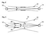
- FIG. 2 Transmitted light cone and received light cone according to the prior art drawn. Both cones meet the standard condition that their opening angle is at most equal to a standard opening angle.
- the alignment condition here is a two-stage: As in the case of the invention, the transmission unit 12 in the prior art must be located in the receiving light cone of the reception unit 14. In addition, however, the receiving unit 14 must be in the transmitted light cone. This latter condition is inventively fulfilled from the outset because of the size of the transmitted light cone.
- FIG. 3 shows a plan view of an optoelectronic sensor 10 from a transmitting unit 12 and a receiving unit 14 according to the invention.
- Safety standards prescribe a reflection security of the sensor 10 with respect to reflective surfaces which have a prescribed minimum distance to the sensor 10. Reflection means that light of the transmitting unit 12 does not reach the associated receiving unit 14 on the direct path, but instead after reflection at one or more reflecting surfaces. In this case, the direct path from the transmitting unit 12 to the receiving unit 14 could be blocked by an object in the monitoring area, but this escapes the evaluation means because the light still strikes the indirect path after reflections of the receiving unit 14. This malfunction should not occur because the health of the operator may depend on it.
- the safety standard is therefore satisfied only if no position and orientation of one or more reflective surfaces is conceivable that maintain a minimum distance to the sensor 10 and still lead to a mirroring.
- This minimum distance thus defines a standard range as a "tunnel" or cylinder around the connection axis between the transmitting unit 12 and the receiving unit 14. Within this standard range, a mirroring may also take place.
- the specified by the standard minimum distance Z is not constant, but depending on the distance between the transmitting unit 12 and receiving unit 14th
- the minimum distance Z of that region beyond which it is no longer possible to recirculate can be determined by a reflecting surface 26 at the most unfavorable position imaginable. As in FIG. 3 easily recognizable, could a surface 26 at a greater distance Z than the illustrated surface 26 no light in reflect the acceptance angle a, in contrast to an increased acceptance angle a '.
- the transmitting unit 12 When aligning the sensor 10 in a teaching phase, the transmitting unit 12 is now turned on and determines where its light impinges on a receiving chip, that is, which light receiving elements are covered by a light spot.
- the evaluation means stores the position or identity of these light-receiving elements as a target position. Thus, it is sufficient if the operator aligns the sensor 10 accurately enough that the light spot ever hits the receiving chip somewhere.
- the size of the receiving chip 24 is limited primarily by manufacturing costs, with a larger and finer-resolution matrix is more expensive, but allows a simpler and more accurate alignment. From a cost point of view, choose whether to use a matrix of 16x16, 128x128 or even more pixels.
- a direct light connection between the transmitting unit 12 and the receiving unit 14 is then accepted by the evaluation means only if precisely those pixels of transmitted light have been learned which have been taught in the desired position.
- the other pixels are quasi muted in this evaluation.
- the light arriving there can still be evaluated, for example to gain information about disturbing ambient light. If the transmitted light from another direction, it no longer falls to the target position below the learned light spot, but to other light receiving elements in another position.
- the evaluation means receives light of the transmitting unit 12, but not at the learned and expected target position. This is treated in the evaluation means as an interrupted light beam. For there are only two reasons for a wandering of the receiving position on the receiving chip, both of which must lead to a response of the sensor 10. Either the sensor 10 is misaligned or the transmitted light is not on a direct but after being reflected on an indirect path to the receiving unit 14 passes.
- the spatially resolving receiving unit 14 By the spatially resolving receiving unit 14 so that the alignment is greatly facilitated.
- the desired position the size and positional accuracy of which depends on the resolution capability of the matrix of the receiving unit and the quality of the receiving optics, thus ultimately determines the acceptance angle. Therefore, the required standard opening angle can also be set with a simple alignment method.
- the teach-in of the desired position allows either to dispense on the receiving side on a mechanical aperture.
Abstract
Description
Die Erfindung betrifft ein Verfahren zum Betrieb eines optoelektronischen Sensors mit mindestens einer Sendeeinheit zum Aussenden von Lichtsignalen in einen Überwachungsbereich, mindestens einer Empfangseinheit zum Empfang der von der Sendeeinheit ausgesandten Lichtsignale und einer Steuer- und Auswerteelektronik zur Steuerung der Sende- und Empfangseinheit und zur Auswertung des von der Empfangseinheit empfangenen Lichtsignals und einen so ausgestalteten optoelektronischen Sensor.The invention relates to a method for operating an optoelectronic sensor having at least one transmitting unit for emitting light signals in a monitoring area, at least one receiving unit for receiving the light signals emitted by the transmitting unit and a control and evaluation for controlling the transmitting and receiving unit and for evaluating the from the receiving unit received light signal and thus configured optoelectronic sensor.
Derartige optoelektronische Sensoren werden beispielsweise zur Zugangsüberwachung in Form von Lichtgittern eingesetzt. Anwendungen sind z.B. die Zugangssicherung von automatischen Fertigungsanlagen, die Absicherung von Einfahrtsöffnungen zu Fertigungszellen, die Absicherung von Abkantpressen und Palettieranlagen, die Transporttechnik, die Förder- und Lagertechnik, die Verpackungsindustrie, der Maschinenbau und die Automobilindustrie.Such optoelectronic sensors are used, for example, for access control in the form of light grids. Applications are e.g. the safeguarding of access to automatic production facilities, the protection of access openings to production cells, the protection of press brakes and palletizing systems, transport technology, conveyor and warehouse technology, the packaging industry, mechanical engineering and the automotive industry.
Falls ein nicht zugelassenes Objekt das Lichtgitter durchtritt, wird eine Sicherheitsfunktion ausgelöst, z.B. ein Alarm ausgelöst, eine gefährdende Produktionsmaschine abgeschaltet oder dergleichen.If an unauthorized object passes the light curtain, a safety function is triggered, e.g. an alarm is triggered, a hazardous production machine switched off or the like.
Der Nachweis eines Gegenstandes im Lichtgitter beruht darauf, dass es zu einer Reduktion des Energieeintrages in eine gegebene Empfangseinheit kommt, weil der Gegenstand im Lichtstrahl die Empfangseinheit abschattet. Man führt daher eine Schaltschwelle für das Empfängersignal ein, bei deren Unterschreitung ein Schaltprozess ausgelöst wird, der anzeigt, dass ein Gegenstand in das Lichtgitter eingedrungen ist, was ggf. zum Auslösen einer Sicherheitsfunktion führt.The proof of an object in the light grid is based on the fact that it comes to a reduction of the energy input into a given receiving unit, because the object in the light beam shadows the receiving unit. It therefore introduces a switching threshold for the receiver signal, which falls below a switching process is triggered, indicating that an object has penetrated into the light grid, which possibly leads to the triggering of a safety function.
Naturgemäß muss in sicherheitsrelevanten Anwendungen vermieden werden, dass durch eine andere Lichtquelle ein zusätzlicher Energieeintrag in eine gegebene Empfangseinheit erfolgt, da dieser zusätzliche Energieeintrag dazu führen könnte, dass die Schaltschwelle nicht mehr unterschritten wird, obwohl sich eigentlich ein Objekt im Strahlengang befindet, das zum Auslösen der Sicherheitsfunktion führen müsste.Naturally, in safety-relevant applications it must be avoided that an additional energy input into a given receiving unit occurs through another light source, since this additional energy input could lead to the switching threshold no longer being undershot, even though an object is actually located in the beam path the safety function would have to lead.
Daraus wird deutlich, dass zwischen dem Lichtstrahl, der von einer gegebenen Empfangseinheit zugeordneten Sendeeinheit ausgestrahlt und in die zugeordnete Empfangseinheit eingestrahlt wird und dem Lichtsignal, das in die betreffende Empfangseinheit eingestrahlt wird und den Lichtstrahl sowie weitere Beiträge, wie das Umgebungslicht oder auch die von benachbarten Sendeeinheiten abgestrahlten Lichtstrahlen umfasst, klar zu unterscheiden ist.It is clear that between the light beam emitted by a given receiving unit transmitting unit and irradiated in the associated receiving unit and the light signal which is radiated into the respective receiving unit and the light beam and other contributions, such as the ambient light or that of adjacent Transmitter units radiated light beams, is clearly distinguished.
Aus diesem Grund werden üblicherweise die Sendeeinheiten optoelektronischer Sensorsysteme so konzipiert, dass sie die zur Sendeeinheit gehörende Lichtquelle optisch durch eine oder mehrere Linsen der Sendeeinheit so nachbearbeiten, dass der schließlich von der Sendeeinheit ausgesandte Lichtstrahl mit einem kleinen Öffnungswinkel, typischerweise zwischen 1 und 2°, oder sogar mit konstantem Radius ausgesendet wird. Da zugleich ein gewisser Öffnungswinkel oder Radius des ausgesandten Lichtstrahls notwendig ist, um eine effiziente Überwachung des Schutzraums zu gewährleisten, müssen diese Linsen abgesetzt, in einem gewissen Abstand von der Lichtquelle angeordnet sein. Dies bezeichnet man als "abgesetzte Optik".For this reason, the transmitting units of optoelectronic sensor systems are usually designed such that they process the light source belonging to the transmitting unit optically by one or more lenses of the transmitting unit such that the light beam finally emitted by the transmitting unit with a small opening angle, typically between 1 and 2 °, or even sent out with a constant radius. Since at the same time a certain opening angle or radius of the emitted light beam is necessary to ensure efficient monitoring of the shelter, these lenses must be discontinued, be arranged at a certain distance from the light source. This is called a "remote optics".
In im Wesentlichen gleicher Weise werden bekannte Empfangseinheiten so aufgebaut, dass sie nur einen begrenzten Akzeptanzwinkel aufweisen.In substantially the same way, known receiving units are constructed so that they have only a limited acceptance angle.
Die
Die
Die
Die
Es ist zur Reduktion des negativen Effektes des Eintrags von Umgebungslicht auf die Funktion eines Lichtgitters z.B. aus der
Nachteilig bei den aus dem Stand der Technik bekannten Systemen ist, dass die derart aufgebauten optoelektronischen Sensoren aufwendig zu justieren sind, da Sende- und Empfangseinheit relativ zueinander so ausgerichtet werden müssen, dass zumindest ein Teil des von einer Sendeeinheit ausgesandten Lichtstrahls in den Akzeptanzwinkel der zugeordneten Empfangseinheit fällt. Darüber hinaus ist das Vorsehen einer abgesetzten Optik wegen der Materialkosten für die Linsen teuer. Weiter gesteigert wird die Kostenbelastung dadurch, dass wegen notwendiger hoher Präzision der räumlichen Anordnung der abgesetzten Optik die Fertigung der Sendeeinheiten hochpräzise durchgeführt werden muss.A disadvantage of the systems known from the prior art is that the thus constructed optoelectronic sensors are complicated to adjust, since transmitting and receiving unit must be aligned relative to each other so that at least a portion of the light emitted by a transmitting unit light beam in the acceptance angle of the associated Receiver unit drops. Moreover, the provision of offset optics is expensive because of the material cost of the lenses. The cost burden is further increased by the fact that because of the necessary high precision of the spatial arrangement of the remote optics, the production of the transmitting units must be carried out with high precision.
Aufgabe der Erfindung ist daher, ein Verfahren zum Betrieb eines optoelektronischen Sensors und einen optoelektronischen Sensor zu schaffen, das/der kostengünstiger ist und die Anforderungen an die Justage des optoelektronischen Sensors reduziert.The object of the invention is therefore to provide a method for operating an optoelectronic sensor and an optoelectronic sensor, which is less expensive and reduces the requirements for the adjustment of the optoelectronic sensor.
Diese Aufgabe wird gelöst durch ein Verfahren zum Betrieb eines optoelektronischen Sensors mit den Merkmalen des Patentanspruchs 1 und einen optoelektronischen Sensor mit den Merkmalen des Patentanspruchs 4.This object is achieved by a method for operating an optoelectronic sensor having the features of patent claim 1 and an optoelectronic sensor having the features of patent claim 4.
Vorteilhafte Ausführungen und Weiterbildungen der Erfindung sind in den jeweils rückbezogenen Unteransprüchen angegeben.Advantageous embodiments and modifications of the invention are specified in the respective dependent subclaims.
Der Erfindung liegt die Erkenntnis zugrunde, dass durch einen mindestens einmal, z.B. bei der Initialisierung des Lichtgitters, durchgeführten Verfahrensschritt, während dessen eine Anpassung der Sendeleistung der Sendeeinheit und/oder einer empfangsseitigen Bewertungsschwelle vorgenommen wird, die sicherstellt, dass die Codierung des durch die Sendeeinheit ausgesendeten Lichtsignals maximale Wirksamkeit entfaltet, das bisherige Erfordernis, mit einem kleinen Öffnungswinkel von 1 bis 2° oder parallel von der Sendeeinheit ausgesandten Lichtstrahlen zu arbeiten, ohne Einbuße von Sicherheit entfallen kann.The invention is based on the knowledge that at least once, e.g. during the initialization of the light grid, carried out process step, during which an adjustment of the transmission power of the transmitting unit and / or a receiving side evaluation threshold is made, which ensures that the coding of the transmitted light emitted by the transmitting unit maximum effectiveness unfolds, the previous requirement, with a small opening angle to work from 1 to 2 ° or parallel emitted by the transmitting unit light beams, can be omitted without loss of security.
Das erfindungsgemäße Verfahren zum Betrieb eines optoelektronischen Sensors mit mindestens einer Empfangseinheit, mindestens einer der Empfangseinheit zugeordneten Sendeeinheit und einer Steuer- und Auswerteelektronik umfasst wenigstens die folgenden Schritte: Zunächst wird eine Sendeleistung der mindestens einen Sendeeinheit und/oder einer empfangsseitigen Bewertungsschwelle angepasst. Dabei ist das Kriterium für die Anpassung, dass die Empfangseinheit gerade unterhalb der Sättigung arbeitet. Wenn dies der Fall ist, ist das Zeitverhalten der Empfangseinheit optimal, so dass der Nachweis von Pulssequenzen besonders gut funktioniert.The method according to the invention for operating an optoelectronic sensor having at least one receiving unit, at least one transmitting unit assigned to the receiving unit and control and evaluation electronics comprises at least the following steps: First, a transmitting power of the at least one transmitting unit and / or a receiving-side rating threshold is adapted. The criterion for the adaptation is that the receiving unit is working just below saturation. If this is the case, the time response of the receiving unit is optimal, so that the detection of pulse sequences works very well.
Ferner wird ein Code durch die mindestens eine Sendeeinheit ausgesendet. Der Code gibt eine korrelierte Folge von Lichtpulsen an, die die mindestens eine Sendeeinheit als Lichtstrahl abgibt, wenn sie von der Steuer- und Auswerteelektronik angesteuert wird. Dabei gibt die Sendeeinheit Lichtpulse mit einem Öffnungswinkel von mindestens 10°, vorzugsweise 20° ab, was beispielsweise durch Verwendung einer LED ohne abgesetzte Optik möglich ist.Furthermore, a code is transmitted by the at least one transmitting unit. The code indicates a correlated sequence of light pulses which the at least one transmitting unit emits as a light beam when it is driven by the control and evaluation electronics. In this case, the transmitting unit emits light pulses with an opening angle of at least 10 °, preferably 20 °, which is possible, for example, by using an LED without remote optics.
Ferner muss ein von der mindestens einen Empfangseinheit empfangenes Signal zur Feststellung einer etwaigen Abschattung des von der mindestens einen Sendeeinheit abgegebenen Lichtstrahls ausgewertet werden. Dies geschieht unter Berücksichtigung der Folge von Lichtpulsen; nur solche Lichteinträge, die dem Code der der Empfangseinheit zugeordneten Sendeeinheit entsprechende Pulssequenz aufweisen, werden bei der Analyse, ob eine Abschattung bzw. ein nicht zugelassener Eingriff ins Schutzfeld erfolgt ist, berücksichtigt.Furthermore, a signal received by the at least one receiving unit must be evaluated for determining any shading of the light beam emitted by the at least one transmitting unit. This happens under Consideration of the sequence of light pulses; Only those light entries which have the pulse sequence corresponding to the code of the transmitting unit assigned to the receiving unit are taken into account in the analysis as to whether shadowing or an unauthorized intervention into the protective field has taken place.
Diese Vorgehensweise bringt signifikante Vorteile mit sich. Durch die Verwendung von Lichtstrahlen mit einem im Vergleich zu den üblichen Öffnungswinkeln großen Öffnungswinkel von über 10° wird die Justage des optoelektronischen Sensors weitgehend entschärft, da auch dann, wenn eine Fehljustage von einigen Grad vorliegt, noch der gesamte Akzeptanzwinkel der Empfangseinheit ausgeleuchtet wird. Gleichzeitig kann bei Einsatz des erfindungsgemäßen Verfahrens auf eine abgesetzte Optik der Sendeeinheit verzichtet werden, was die Kosten für diese Optik einspart und die Präzisionserfordernisse bei der Herstellung der Sendeeinheit senkt, was weitere Kostenvorteile mit sich bringt.This approach brings significant benefits. By using light beams with a large compared to the usual opening angle opening angle of about 10 °, the adjustment of the optoelectronic sensor is largely mitigated, because even if a misalignment of some degrees, nor the entire acceptance angle of the receiving unit is illuminated. At the same time can be dispensed with a remote optics of the transmitter unit when using the method according to the invention, which saves the cost of these optics and reduces the precision requirements in the production of the transmitter unit, which brings further cost advantages.
Eine besonders vorteilhafte Ausgestaltung des Verfahrens sieht vor, dass beim Schritt des Anpassens der Sendeleistung der mindestens einen Sendeeinheit und/oder der empfangsseitigen Bewertungsschwelle die Sendeleistung der mindestens einen Sendeeinheit so lange geändert wird, bis die Empfangseinheit in ihren Arbeitsbereich gekommen ist.A particularly advantageous embodiment of the method provides that, in the step of adapting the transmission power of the at least one transmission unit and / or the reception-side evaluation threshold, the transmission power of the at least one transmission unit is changed until the reception unit has come into its working range.
Man geht also von einem zu starken Lichtsignal, das die Empfangseinheit sättigt, aus und senkt die Signalintensität ab, bis keine Sättigung mehr vorliegt oder man steigert die Signalintensität schrittweise bis erstmals eine Sättigung der Empfangseinheit vorliegt und reduziert dann die Signalintensität wieder um einen Schritt. Wenn mit stark variierenden Umgebungslichteinträgen zu rechnen ist, kann es auch vorteilhaft sein, eine derartige Anpassung wiederholt vorzunehmen, beispielsweise während ein anderes Paar von Empfangseinheit und der Empfangseinheit zugeordneter Sendeeinheit gerade aktiv sind, sofern dieser Betrieb nicht das Ergebnis der Anpassung verfälscht.It is therefore from too strong a light signal that saturates the receiving unit, and decreases the signal intensity until saturation is no longer present or you increase the signal intensity gradually until the first saturation of the receiving unit is present and then reduces the signal intensity again by one step. If it is to be expected with strongly varying ambient light entries, it may also be advantageous to make such an adjustment repeatedly, for example, while another pair of receiving unit and the receiving unit associated transmitting unit are currently active, unless this operation distorts the result of the adjustment.
Der erfindungsgemäße optoelektronische Sensor umfasst mindestens eine ortsauflösende Empfangseinheit, mindestens eine der Empfangseinheit zugeordnete Sendeeinheit zum Aussenden von Lichtstrahlen mit einem Öffnungswinkel von mindestens 10°, und eine Steuer- und Auswerteelektronik, die zumindest Sendeeinheitenansteuerungsmittel zur Ansteuerung der Sendeeinheiten, Empfangseinheitenansteuerungsmittel zur Ansteuerung der Empfangseinheiten, Auswertemittel zur Auswertung des in die Empfangseinheiten eingestrahlten Signals und zur Prüfung, ob die in eine Empfangseinheit eingestrahlte Lichtenergie eine Schaltschwelle überschreitet, Codesteuermittel zur Ansteuerung der Sendeeinheiten mit einem ausgewählten Code, wobei der Code eine korrelierte Folge von Lichtpulsen angibt, die die mindestens eine Sendeeinheit als Lichtstrahl abgibt, wenn sie angesteuert wird und Korrelationsberechnungsmittel zur Berechnung der Korrelationsfunktion zwischen einem ausgewählten gespeicherten Code und dem in eine oder mehrere angesteuerte Empfangseinheiten eingestrahlten Licht und zur Prüfung, ob die Korrelationsfunktion eine Korrelationsschwelle überschreitet, aufweist, wobei die Sendeeinheitenansteuerungsmittel zur Ansteuerung der Sendeeinheiten und/oder die Empfangseinheitenansteuerungsmittel zur Ansteuerung der Empfangseinheiten zur Anpassung einer Sendeleistung der Sendeeinheiten und/oder zur Festlegung von Empfangsbewertungsschwellen geeignet sind. Der Sensor ist aus den bereits oben bei der Vorstellung des erfindungsgemäßen Verfahrens diskutierten Gründen sehr einfach zu justieren und kostengünstig herzustellen.The optoelectronic sensor according to the invention comprises at least one spatially resolving receiving unit, at least one associated with the receiving unit Transmitting unit for emitting light beams with an opening angle of at least 10 °, and control and evaluation, the at least transmitting unit drive means for controlling the transmitting units, Empfangseinheitansteuerungsmittel for controlling the receiving units, evaluation means for evaluating the irradiated in the receiving units signal and to check whether the in Code control means for driving the transmitting units with a selected code, the code indicating a correlated sequence of light pulses which emits the at least one transmitting unit as a light beam when it is driven and correlation calculating means for calculating the correlation function between a selected one stored code and the irradiated in one or more controlled receiving units light and to check whether the correlation function override a correlation threshold wherein the transmission unit drive means are suitable for controlling the transmission units and / or the reception unit activation means are suitable for controlling the reception units for adapting a transmission power of the transmission units and / or for establishing reception evaluation thresholds. The sensor is very easy to adjust and inexpensive to manufacture from the reasons already discussed above in the presentation of the method according to the invention.
Eine besonders preiswerte Variante des optoelektronischen Sensor liegt vor, wenn die mindestens eine Sendeeinheit eine LED ohne abgesetzte Optik ist.A particularly inexpensive variant of the optoelectronic sensor is present when the at least one transmitting unit is an LED without remote optics.
Weiter ist es vorgesehen, den Akzeptanzwinkel der Empfangseinheit für den laufenden Betrieb des optoelektronischen Sensors anzupassen bzw. einzustellen, insbesondere zu verringern, um Anforderungen der Normen, insbesondere der IEC 61496-2 bezüglich der Abstände zu spiegelnden Flächen zu erfüllen. Hierzu weist die Empfangseinheit entsprechende Mittel zur Anpassung des empfangsseitigen Akzeptanzwinkels auf.Furthermore, it is provided to adapt or adjust the acceptance angle of the receiving unit for the ongoing operation of the optoelectronic sensor, in particular to reduce it in order to meet requirements of the standards, in particular of IEC 61496-2 with respect to the distances to be mirrored surfaces. For this purpose, the receiving unit has corresponding means for adapting the reception-side acceptance angle.
Zunächst steht durch die Nutzung der gesamten photoempfindlichen Fläche der ortsauflösenden Empfangseinheit ein großer Akzeptanzwinkel zur Verfügung, so dass die Sendeeinheit und Empfangseinheit gut zueinander justiert werden können.First, by using the entire photosensitive surface of the spatially resolving receiving unit, a large acceptance angle is available that the transmitting unit and receiving unit can be well adjusted to each other.
Nach der Justage, für den regulären Betrieb des optoelektronischen Sensors, wird dann der Akzeptanzwinkel soweit reduziert, dass die Anforderungen an die Abstände zu spiegelnden Flächen erfüllt werden. Dies geschieht beispielsweise durch eine elektronische Ausblendung einzelnder Pixel der ortsauflösenden Empfangseinheit, beispielsweise eines CCD- oder CMOS-Bildaufnehmers.After the adjustment, for the regular operation of the optoelectronic sensor, the acceptance angle is then reduced to the extent that the requirements for the distances to be mirrored surfaces are met. This is done, for example, by an electronic blanking of individual pixels of the spatially resolving receiving unit, for example a CCD or CMOS image recorder.
Im Folgenden wird die Erfindung anhand der beigefügten Figur näher erläutert.In the following the invention will be explained in more detail with reference to the attached figure.
Es zeigt
- Fig. 1
- ein Lichtgitter gemäß einer Ausführungsform der Erfindung;
- Fig. 2:
- ein Lichtgitter gemäß dem Stand der Technik;
- Fig. 3
- ein Lichtgitter gemäß
Figur 1 mit Einstellung eines Aktzeptanzwinkels bei der Empfangseinheit.
- Fig. 1
- a light grid according to an embodiment of the invention;
- Fig. 2:
- a light grid according to the prior art;
- Fig. 3
- a light grid according to
FIG. 1 with setting of an acceptance angle at the receiving unit.
Die Empfangseinheit 14 weist jeweils einen eigentlichen Lichtempfänger oder Empfangschip und eine zugeordnete Empfangsoptik auf. Der Empfangschip ist ortsauflösend, beispielsweise eine PSD (Position sensing diode) oder ein Chip mit einzelnen Empfangspixeln wie ein CCD- oder CMOS Chip. Dabei können die Empfangspixel insbesondere zeilen- oder matrixförmig angeordnet sein.The
Die Steuer- und Auswerteelektronik 18 weist als Bestandteile insbesondere Sendeeinheitenansteuerungsmittel AS zur Ansteuerung der Sendeeinheiten 12 und Empfangseinheitenansteuerungsmittel AE zur Ansteuerung der Empfangseinheiten 14, Auswertemittel AUS zur Auswertung des in die Empfangseinheiten 14 eingestrahlten Lichtsignals und zur Prüfung, ob die in eine Empfangseinheit 14 eingestrahlte Lichtenergie eine Schaltschwelle überschreitet sowie zum Auslösen einer Sicherheitsfunktion, Codesteuermittel SC zur Ansteuerung der Sendeeinheit 12 mit einem Code, der aus einer Sequenz von Lichtpulsen besteht und Korrelationsberechnungsmittel KF zur Berechnung der Korrelationsfunktion zwischen dem Code und dem in die angesteuerte Empfangseinheit 14 eingestrahlten Licht auf.The control and
Bei allen vorstehend aufgezählten Mitteln wird es sich in der Regel um Funktionsblöcke einer Schaltung oder Kombinationen von Funktionsblöcken einer Schaltung handeln, sie können aber auch separat oder in Gruppen zusammengefasst ausgeführt sein.All of the above listed means will usually be function blocks of a circuit or combinations of function blocks of a circuit, but they may also be implemented separately or in groups.
Ferner zeigt die Figur den Öffnungswinkel o des durch die Sendeeinheit 12 ausgesandten Lichtstrahls, der mindestens 10° betragen muss und in der in der Figur dargestellten Ausführungsform 20° beträgt. Ebenfalls eingezeichnet ist der Akzeptanzwinkel a der Empfangseinheit, der nur wenige Grad beträgt. In dieser Darstellung wird besonders deutlich, dass der erfindungsgemäß ausgestaltete optoelektronische Sensor 10 leicht zu justieren ist, denn solange sich der Akzeptanzwinkel a vollständig im durch den Öffnungswinkel o definierten Kegel befindet, ist die zuverlässige Funktion des optoelektronischen Sensors gewährleistet.Further, the figure shows the opening angle o of the light beam emitted by the transmitting
Zum Betrieb des optoelektronischen Sensors 10 wird in der Regel zunächst eine Synchronisation der Sendeeinheiten 12 und Empfangseinheiten 14 durchgeführt. Dies geschieht mit Hilfe einer bestimmten, nur für die Synchronisation reservierten Pulsfolge.For the operation of the
Ferner erfolgt die Anpassung der Sendeleistung der Sendeeinheit 12 und/oder der Empfangsschwellen der Empfangseinheit 14. Wesentliches Kriterium ist dabei, die Empfangseinheit 14, genauer gesagt den zu ihr gehörenden Lichtdetektor, in seinem Arbeitsbereich, vorzugsweise knapp unterhalb der Sättigung zu betreiben, um ein besonders gutes Zeitverhalten, das für den Betrieb mit Codes notwendig ist, zu erreichen.Furthermore, the adaptation of the transmission power of the transmitting
Anschließend erfolgt die automatisierte Auswahl oder der Abruf eines vorgegebenen Codes, mit dem der optoelektronische Sensor 10 betrieben wird. Bei den Codes handelt es sich um Informationen, die mit Hilfe der Codesteuermittel SC und der Sendeeinheitenansteuerungsmittel AS in eine Folge von Lichtpulsen, die von den angesteuerten Sendeeinheiten 12 als Lichtstrahl 22 abgegeben werden, umgesetzt werden können. Ein gegebener Code entspricht also einer Folge von Lichtpulsen, insbesondere einer Folge von orthogonalen oder näherungsweise orthogonalen Lichtpulsen.Subsequently, the automated selection or the retrieval of a predetermined code, with which the
Dieser Code wird dann an das Codesteuermittel SC übergeben und von diesem dazu verwendet, mit Hilfe der Sendeeinheitenansteuerungsmittel AS die Sendeeinheit zu veranlassen, wenn sie angesteuert werden, eine dem Code entsprechende Folge korrelierter Lichtpulse als Lichtstrahl 22 auszusenden.This code is then passed to the code control means SC and used by the latter, with the aid of the transmission unit drive means AS to cause the transmission unit, when they are driven, to emit a sequence of correlated light pulses corresponding to the code as
Mit diesem automatisch bestimmten Code erfolgt dann der übliche Betrieb eines optoelektronischen Sensors. Da bei diesem meist eine Vielzahl von paarweise einander zugeordneten Sendeeinheiten 12 und Empfangseinheiten 14 vorhanden sind, von denen im Betrieb meist zu einem gegebenen Zeitpunkt nur einzelne Paare von einander zugeordneten Sendeeinheiten 12 und Empfangseinheiten 14 verwendet werden, ist es auch denkbar, während des laufenden Betriebes mit Hilfe von gerade nicht paarweise mit einer Sendeeinheit 12 angesteuerten Empfangseinheiten 14, für die insbesondere ein signifikanter Beitrag des Lichtstrahles 22 der gerade angesteuerten Sendeeinheit 12 zum Lichtsignal ausgeschlossen ist, die Anpassung der Sendeleistung und/oder der Empfangsschwellen periodisch oder kontinuierlich aufzufrischen.With this automatically determined code then the usual operation of an optoelectronic sensor. Since in this usually a plurality of pairwise associated transmitting
Die Sendeeinheit 12 strahlt ihr Licht in einen großen Winkelbereich, der ohne besondere Bündelungsmaßnahmen nur grob in Richtung der Empfangseinheit 14 liegt. Deshalb benötigen die Sendeeinheit 12 auch keine Blenden oder Sendeoptik. Es kann eine Sendeoptik zu dem Zweck vorhanden sein, das Licht zur Erreichung einer größeren Reichweite zu bündeln. Diese Sendeoptik ist aber nicht dafür ausgebildet, eine Umspiegelungssicherheit zu erreichen und soll nicht zu genau fokussieren, so dass die Sendeeinheit 12 stets wegen ihres großen Sendeöffnungswinkels sehr einfach ausgerichtet werden können. Der Winkelbereich ist in der Realität durch einen Raumwinkel festgelegt, und der von der Sendeeinheit 12 lichterfüllte Bereich bildet einen Sendelichtkegel. Da dieser Sendelichtkegel einen so großen Öffnungswinkel hat, ist von vorneherein oder nach allenfalls sehr grober und einfacher Ausrichtung sichergestellt, dass die zugehörige Empfangseinheit 14 innerhalb des Sendelichtkegels liegt.The transmitting
Auf die Empfangseinheit 14 umgekehrt trifft nur solches Licht, das innerhalb eines Empfangslichtkegels des Akzeptanzwinkels a liegt. Damit die zugehörige Sendeeinheit 14 innerhalb des Akzeptanzwinkels a liegt, muss die Empfangseinheit 14 genau gegenüber der zugehörigen Sendeeinheit 12 ausgerichtet sein. Der Aktzeptanzwinkel a kann durch Blenden und/oder die Empfangsoptik 26 eingestellt werden. Die Ortsauflösung des Empfangschips 24 ermöglicht aber sowohl eine einfache Einstellung des Akzeptanzwinkels a als auch eine erheblich erleichterte Ausrichtung, wie weiter unten noch im Zusammenhang mit den
Um die Bedingung an den Akzeptanzwinkels a des Empfangslichtkegels besser zu verstehen, sind in
Im Stand der Technik sorgt die doppelte Bedingung durch den schmalen Sende- und Empfangslichtkegel für ausreichende Umspiegelungssicherheit.In the prior art, the double condition ensures sufficient Umspiegelungssicherheit by the narrow transmitting and receiving light cone.
Sicherheitsnormen, insbesondere die IEC 61496-2, schreiben eine Umspiegelungssicherheit des Sensors 10 gegenüber reflektierenden Flächen vor, die einen vorgeschriebenen Mindestabstand zu dem Sensor 10 haben. Umspiegelung bedeutet, dass Licht der Sendeeinheit 12 nicht auf dem direkten Weg, sondern nach Reflexion an einer oder mehreren reflektierenden Flächen zu der zugehörigen Empfangseinheit 14 gelangt. Dabei könnte der direkte Weg von der Sendeeinheit 12 zu der Empfangseinheit 14 durch ein Objekt in dem Überwachungsbereich blockiert sein, was aber dem Auswertemittel entgeht, weil das Licht auf dem indirekten Weg nach Umspiegelungen der Empfangseinheit 14 dennoch trifft. Diese Fehlfunktion darf nicht auftreten, da die Gesundheit des Bedienpersonals davon abhängen kann.Safety standards, in particular IEC 61496-2, prescribe a reflection security of the
Die Sicherheitsnorm ist daher nur erfüllt, wenn keine Position und Orientierung einer oder mehrerer reflektierender Flächen denkbar ist, die einen Mindestabstand zu dem Sensor 10 einhalten und dennoch zu einer Umspiegelung führen. Dieser Mindestabstand definiert also einen Normbereich als "Tunnel" oder Zylinder um die Verbindungsachse zwischen Sendeeinheit 12 und Empfangseinheit 14. Innerhalb dieses Normbereichs darf auch eine Umspiegelung stattfinden. Der von der Norm festgelegte Mindestabstand Z ist nicht konstant, sondern abhängig von dem Abstand zwischen Sendeeinheit 12 und Empfangseinheit 14.The safety standard is therefore satisfied only if no position and orientation of one or more reflective surfaces is conceivable that maintain a minimum distance to the
Der Mindestabstand Z desjenigen Bereichs, außerhalb dessen keine Umspiegelung mehr möglich ist, kann durch eine spiegelnde Fläche 26 an der denkbar ungünstigsten Position bestimmt werden. Wie in
Anhand der
Bei der Ausrichtung des Sensors 10 in einer Einlernphase wird nun die Sendeeinheit 12 eingeschaltet und ermittelt, wo ihr Licht auf einem Empfangschip auftrifft, das heißt welche Lichtempfangselemente von einem Lichtfleck überdeckt sind. Das Auswertemittel speichert die Position beziehungsweise Identität dieser Lichtempfangselemente als eine Sollposition. Somit genügt es, wenn der Bediener den Sensor 10 genau genug ausrichtet, dass der Lichtfleck überhaupt irgendwo den Empfangschip trifft. Die Größe des Empfangschips 24 ist dabei in erster Linie durch Herstellungskosten begrenzt, wobei eine größere und feiner aufgelöste Matrix zwar teurer ist, aber eine einfachere und genauere Ausrichtung ermöglicht. Hier ist unter Kostengesichtspunkten zu wählen, ob eine Matrix von 16x16, 128x128 oder noch mehr Pixeln eingesetzt wird.When aligning the
Im Betrieb wird dann eine direkte Lichtverbindung zwischen Sendeeinheit 12 und Empfangseinheit 14 von dem Auswertemittel nur dann angenommen, wenn genau diejenigen Pixel von Sendelicht getroffen sind, die in der Sollposition eingelernt worden sind. Die übrigen Pixel sind bei dieser Auswertung quasi stumm geschaltet. Das dort eintreffende Licht kann aber dennoch ausgewertet werden, beispielsweise um Informationen über störendes Umgebungslicht zu gewinnen. Trifft das Sendelicht aus einer anderen Richtung ein, so fällt es nicht mehr auf die Sollposition unterhalb des eingelernten Lichtflecks, sondern auf andere Lichtempfangselemente an einer anderen Position. Das Auswertemittel empfängt also zwar Licht der Sendeeinheit 12, aber nicht an der eingelernten und erwarteten Sollposition. Dies wird in dem Auswertemittel so behandelt wie ein unterbrochener Lichtstrahl. Es gibt nämlich für ein Wandern der Empfangsposition auf dem Empfangschip nur zwei Gründe, die beide zu einem Ansprechen des Sensors 10 führen müssen. Entweder ist der Sensor 10 dejustiert oder das Sendelicht ist nicht auf einem direkten, sondern nach Umspiegelung auf einem indirekten Weg zur Empfangseinheit 14 gelangt.In operation, a direct light connection between the transmitting
Durch die ortsauflösende Empfangseinheit 14 wird damit die Ausrichtung erheblich erleichtert. Die Sollposition, deren Größe und Lagegenauigkeit von der Auflösungsfähigkeit der Matrix der Empfangseinheit und der Güte der Empfangsoptik abhängt, legt somit letztlich den Akzeptanzwinkel fest. Deshalb lässt sich auch der geforderte Normöffnungswinkel mit einem einfachen Ausrichtverfahren einstellen. Das Einlernen der Sollposition ermöglicht wahlweise, auch empfangsseitig auf eine mechanische Blende zu verzichten.By the spatially resolving receiving
- 1010
- Optoelektronischer SensorOptoelectronic sensor
- 1212
- Sendeeinheittransmission unit
- 1414
- Empfangseinheitreceiver unit
- 1818
- Steuer- und AuswerteelektronikControl and evaluation electronics
- 2222
- Lichtstrahlbeam of light
- 2424
- Akzeptanzbereichacceptance range
- 2626
- spiegelnde Flächereflecting surface
- ASAS
- SendeeinheitenansteuerungsmittelTransmission unit control means
- AEAE
- EmpfangseinheitenansteuerungsmittelReceiver unit targeting agents
- AUSOUT
- Auswertemittelevaluation
- SCSC
- CodesteuermittelCode control means
- KFKF
- KorrelationsberechnungsmittelCorrelation calculation means
- oO
- Öffnungswinkelopening angle
- aa
- Akzeptanzwinkelacceptance angle
Claims (4)
- A method of operating an optoelectronic sensor (10) having at least one receiver unit (14) and at least one transmitter unit (12) associated with the receiver unit (14) and having control and evaluation electronics (18), comprising the steps:- adapting a transmission power of the at least one transmitter unit (12) and/or an evaluation threshold at the reception side;- transmitting a code by the at least one transmitter unit (12), wherein the code sets a correlated sequence of light pulses which the at least one transmitter unit (12) outputs as a light beam (22) when it is controlled by control and evaluation electronics (18); and- evaluating a signal received by the at least one receiver unit (14) for determining a shadowing of the light beam (22) output by the at least one transmitter unit (12),characterised in that
the at least one receiver unit (14) is spatially resolving with a respective photosensitive surface and a respective associated receiver optics; and in that the at least one transmitter unit outputs light pulses with an opening angle (o) of at least 10° and an acceptance angle (a) at the reception side for the regular operation is reduced after an adjustment. - A method in accordance with claim 1,
characterised in that, in the step of adapting the transmission power of the at least one transmitter unit (12) and/or the evaluation threshold at the reception side, the transmission power of the at least one transmitter unit is changed for so long until the receiver has reached its working range. - An optoelectronic sensor (10), comprising
at least one receiver unit (14),
at least one transmitter unit (12) associated with the receiver unit (14), control and evaluation electronics (18) which have at least transmitter unit control means (AS) for controlling the transmitter units (12), receiver unit control means (AE) for controlling the receiver units (14), evaluation means (AUS) for evaluating the signal radiated into the receiver units (14) and for checking whether the light energy radiated into a receiver unit (14) exceeds a switching threshold, code control means (SC) for controlling the transmitter units by a selected code, with the code setting a correlated sequence of light pulses which the at least one transmitter unit (12) outputs as a light beam (22) when it is controlled, correlation calculation means (KF) for calculating the correlation function between a selected code and the light radiated into one or more controlled receiver units (14) and for checking whether the correlation function exceeds a correlation threshold,
wherein the transmitter unit control means (AS) are suitable for controlling the transmitter units (12) and/or the receiver unit control means (AE) are suitable for controlling the receiver units (14) for adapting a transmission power of the transmitter units (12) and/or for fixing reception evaluation thresholds, characterised in that
the at least one receiver unit (14) is spatially resolving with a respective photosensitive surface and a respective associated receiver optics and the at least one transmitter unit is designed for transmitting light beams with an opening angle of at least 10° and the at least one spatially resolving receiver unit has means for reducing an acceptance angle (a) at the reception side for the regular operation after an adjustment. - An optoelectronic sensor (10) in accordance with claim 3, characterised in that the at least one transmitter unit is an LED without an offset optics.
Priority Applications (2)
| Application Number | Priority Date | Filing Date | Title |
|---|---|---|---|
| EP09172533A EP2312340B1 (en) | 2009-10-08 | 2009-10-08 | Method for operating an optoelectronic sensor and optoelectronic sensor |
| AT09172533T ATE537471T1 (en) | 2009-10-08 | 2009-10-08 | METHOD FOR OPERATING AN OPTOELECTRONIC SENSOR AND OPTOELECTRONIC SENSOR |
Applications Claiming Priority (1)
| Application Number | Priority Date | Filing Date | Title |
|---|---|---|---|
| EP09172533A EP2312340B1 (en) | 2009-10-08 | 2009-10-08 | Method for operating an optoelectronic sensor and optoelectronic sensor |
Publications (2)
| Publication Number | Publication Date |
|---|---|
| EP2312340A1 EP2312340A1 (en) | 2011-04-20 |
| EP2312340B1 true EP2312340B1 (en) | 2011-12-14 |
Family
ID=41794668
Family Applications (1)
| Application Number | Title | Priority Date | Filing Date |
|---|---|---|---|
| EP09172533A Active EP2312340B1 (en) | 2009-10-08 | 2009-10-08 | Method for operating an optoelectronic sensor and optoelectronic sensor |
Country Status (2)
| Country | Link |
|---|---|
| EP (1) | EP2312340B1 (en) |
| AT (1) | ATE537471T1 (en) |
Families Citing this family (2)
| Publication number | Priority date | Publication date | Assignee | Title |
|---|---|---|---|---|
| DE102016122364B4 (en) * | 2016-11-21 | 2022-09-08 | Sick Ag | Photoelectric sensor and method for monitoring a surveillance area |
| DE202018105666U1 (en) * | 2018-10-02 | 2020-01-03 | Leuze Electronic Gmbh + Co. Kg | Light barrier arrangement |
Family Cites Families (5)
| Publication number | Priority date | Publication date | Assignee | Title |
|---|---|---|---|---|
| DE19926214A1 (en) | 1999-06-09 | 2001-01-11 | Balluff Gebhard Gmbh & Co | Suppression of noise signals in signal from optical sensor or proximity switch by transmitting chirp sequence and autocorrelating |
| DE29923142U1 (en) * | 1999-06-30 | 2000-04-13 | Leuze Electronic Gmbh & Co | Sensitivity control for light sensors |
| DE102006059370A1 (en) * | 2006-12-15 | 2008-06-26 | Sick Ag | light Curtain |
| ATE541227T1 (en) | 2007-07-05 | 2012-01-15 | Sick Ag | LIGHT GRID AND METHOD FOR OPERATING A LIGHT GRID |
| DE102007031430B4 (en) | 2007-07-05 | 2016-12-01 | Sick Ag | Method for operating a light grid and light grid |
-
2009
- 2009-10-08 AT AT09172533T patent/ATE537471T1/en active
- 2009-10-08 EP EP09172533A patent/EP2312340B1/en active Active
Also Published As
| Publication number | Publication date |
|---|---|
| EP2312340A1 (en) | 2011-04-20 |
| ATE537471T1 (en) | 2011-12-15 |
Similar Documents
| Publication | Publication Date | Title |
|---|---|---|
| EP2574718B1 (en) | Safety system for safeguarding a moving, guided motion element against unwanted collisions | |
| EP2469296B1 (en) | Optoelectronic sensor and method for recording and determining the distance of an object | |
| EP2492714B1 (en) | Method for operating a safety light grid and safety light grid | |
| EP1947481B1 (en) | Optoelectronic sensor and method for recording objects in a monitoring area | |
| EP2395368A1 (en) | Distance-measuring laser scanner for detecting objects in a surveillance range | |
| DE10359782A1 (en) | Method and device for surface surveillance | |
| DE102006050189B4 (en) | Light grid with alignment light transmitter and alignment method | |
| EP2378309A1 (en) | Optoelectronic sensor and method for recording information about objects in a monitoring area | |
| EP2453260B2 (en) | Self-testing monitoring sensor | |
| EP0875873B1 (en) | Opto-electronic sensor | |
| EP2312340B1 (en) | Method for operating an optoelectronic sensor and optoelectronic sensor | |
| EP3324217A1 (en) | Optical sensor and method for monitoring a surveillance area | |
| EP1927868B1 (en) | Opto-electronic sensor | |
| DE102018117878A1 (en) | Safety Light Curtain | |
| DE202018104258U1 (en) | Safety Light Curtain | |
| DE202008016946U1 (en) | Light curtain or photocell | |
| EP2722692B1 (en) | Sensor | |
| DE102017103791B4 (en) | Optoelectronic sensor and method for detecting objects | |
| EP1962105B1 (en) | Method for testing the functionality and/or adjusting an opto-electronic sensor assembly | |
| DE102013018800A1 (en) | Method and device for optically determining distances to objects in a surveillance area, in particular in a surveillance area of automatic doors | |
| DE102015000941B3 (en) | Optical measuring device operated by laser waves | |
| EP2584375B1 (en) | Door monitoring sensor and method for monitoring the counter closing edge of a door, in particular of a revolving door | |
| EP2172791B2 (en) | Light grid | |
| EP3736605A2 (en) | Safety laser scanner and method | |
| EP3859379A1 (en) | Optoelectronic sensor with receiving filter adapted to angle-of-view and method for detecting objects |
Legal Events
| Date | Code | Title | Description |
|---|---|---|---|
| PUAI | Public reference made under article 153(3) epc to a published international application that has entered the european phase |
Free format text: ORIGINAL CODE: 0009012 |
|
| 17P | Request for examination filed |
Effective date: 20101004 |
|
| AK | Designated contracting states |
Kind code of ref document: A1 Designated state(s): AT BE BG CH CY CZ DE DK EE ES FI FR GB GR HR HU IE IS IT LI LT LU LV MC MK MT NL NO PL PT RO SE SI SK SM TR |
|
| AX | Request for extension of the european patent |
Extension state: AL BA RS |
|
| GRAP | Despatch of communication of intention to grant a patent |
Free format text: ORIGINAL CODE: EPIDOSNIGR1 |
|
| RIC1 | Information provided on ipc code assigned before grant |
Ipc: G01V 8/10 20060101AFI20110426BHEP |
|
| GRAS | Grant fee paid |
Free format text: ORIGINAL CODE: EPIDOSNIGR3 |
|
| GRAA | (expected) grant |
Free format text: ORIGINAL CODE: 0009210 |
|
| AK | Designated contracting states |
Kind code of ref document: B1 Designated state(s): AT BE BG CH CY CZ DE DK EE ES FI FR GB GR HR HU IE IS IT LI LT LU LV MC MK MT NL NO PL PT RO SE SI SK SM TR |
|
| REG | Reference to a national code |
Ref country code: GB Ref legal event code: FG4D Free format text: NOT ENGLISH |
|
| REG | Reference to a national code |
Ref country code: CH Ref legal event code: EP |
|
| REG | Reference to a national code |
Ref country code: IE Ref legal event code: FG4D |
|
| REG | Reference to a national code |
Ref country code: DE Ref legal event code: R096 Ref document number: 502009002185 Country of ref document: DE Effective date: 20120315 |
|
| REG | Reference to a national code |
Ref country code: NL Ref legal event code: VDEP Effective date: 20111214 |
|
| PG25 | Lapsed in a contracting state [announced via postgrant information from national office to epo] |
Ref country code: LT Free format text: LAPSE BECAUSE OF FAILURE TO SUBMIT A TRANSLATION OF THE DESCRIPTION OR TO PAY THE FEE WITHIN THE PRESCRIBED TIME-LIMIT Effective date: 20111214 Ref country code: NO Free format text: LAPSE BECAUSE OF FAILURE TO SUBMIT A TRANSLATION OF THE DESCRIPTION OR TO PAY THE FEE WITHIN THE PRESCRIBED TIME-LIMIT Effective date: 20120314 |
|
| LTIE | Lt: invalidation of european patent or patent extension |
Effective date: 20111214 |
|
| PG25 | Lapsed in a contracting state [announced via postgrant information from national office to epo] |
Ref country code: LV Free format text: LAPSE BECAUSE OF FAILURE TO SUBMIT A TRANSLATION OF THE DESCRIPTION OR TO PAY THE FEE WITHIN THE PRESCRIBED TIME-LIMIT Effective date: 20111214 Ref country code: NL Free format text: LAPSE BECAUSE OF FAILURE TO SUBMIT A TRANSLATION OF THE DESCRIPTION OR TO PAY THE FEE WITHIN THE PRESCRIBED TIME-LIMIT Effective date: 20111214 Ref country code: HR Free format text: LAPSE BECAUSE OF FAILURE TO SUBMIT A TRANSLATION OF THE DESCRIPTION OR TO PAY THE FEE WITHIN THE PRESCRIBED TIME-LIMIT Effective date: 20111214 Ref country code: GR Free format text: LAPSE BECAUSE OF FAILURE TO SUBMIT A TRANSLATION OF THE DESCRIPTION OR TO PAY THE FEE WITHIN THE PRESCRIBED TIME-LIMIT Effective date: 20120315 Ref country code: SI Free format text: LAPSE BECAUSE OF FAILURE TO SUBMIT A TRANSLATION OF THE DESCRIPTION OR TO PAY THE FEE WITHIN THE PRESCRIBED TIME-LIMIT Effective date: 20111214 Ref country code: SE Free format text: LAPSE BECAUSE OF FAILURE TO SUBMIT A TRANSLATION OF THE DESCRIPTION OR TO PAY THE FEE WITHIN THE PRESCRIBED TIME-LIMIT Effective date: 20111214 |
|
| PG25 | Lapsed in a contracting state [announced via postgrant information from national office to epo] |
Ref country code: CY Free format text: LAPSE BECAUSE OF FAILURE TO SUBMIT A TRANSLATION OF THE DESCRIPTION OR TO PAY THE FEE WITHIN THE PRESCRIBED TIME-LIMIT Effective date: 20111214 |
|
| REG | Reference to a national code |
Ref country code: IE Ref legal event code: FD4D |
|
| PG25 | Lapsed in a contracting state [announced via postgrant information from national office to epo] |
Ref country code: IE Free format text: LAPSE BECAUSE OF FAILURE TO SUBMIT A TRANSLATION OF THE DESCRIPTION OR TO PAY THE FEE WITHIN THE PRESCRIBED TIME-LIMIT Effective date: 20111214 Ref country code: SK Free format text: LAPSE BECAUSE OF FAILURE TO SUBMIT A TRANSLATION OF THE DESCRIPTION OR TO PAY THE FEE WITHIN THE PRESCRIBED TIME-LIMIT Effective date: 20111214 Ref country code: BG Free format text: LAPSE BECAUSE OF FAILURE TO SUBMIT A TRANSLATION OF THE DESCRIPTION OR TO PAY THE FEE WITHIN THE PRESCRIBED TIME-LIMIT Effective date: 20120314 Ref country code: IS Free format text: LAPSE BECAUSE OF FAILURE TO SUBMIT A TRANSLATION OF THE DESCRIPTION OR TO PAY THE FEE WITHIN THE PRESCRIBED TIME-LIMIT Effective date: 20120414 Ref country code: CZ Free format text: LAPSE BECAUSE OF FAILURE TO SUBMIT A TRANSLATION OF THE DESCRIPTION OR TO PAY THE FEE WITHIN THE PRESCRIBED TIME-LIMIT Effective date: 20111214 Ref country code: EE Free format text: LAPSE BECAUSE OF FAILURE TO SUBMIT A TRANSLATION OF THE DESCRIPTION OR TO PAY THE FEE WITHIN THE PRESCRIBED TIME-LIMIT Effective date: 20111214 |
|
| PG25 | Lapsed in a contracting state [announced via postgrant information from national office to epo] |
Ref country code: PT Free format text: LAPSE BECAUSE OF FAILURE TO SUBMIT A TRANSLATION OF THE DESCRIPTION OR TO PAY THE FEE WITHIN THE PRESCRIBED TIME-LIMIT Effective date: 20120416 Ref country code: PL Free format text: LAPSE BECAUSE OF FAILURE TO SUBMIT A TRANSLATION OF THE DESCRIPTION OR TO PAY THE FEE WITHIN THE PRESCRIBED TIME-LIMIT Effective date: 20111214 Ref country code: RO Free format text: LAPSE BECAUSE OF FAILURE TO SUBMIT A TRANSLATION OF THE DESCRIPTION OR TO PAY THE FEE WITHIN THE PRESCRIBED TIME-LIMIT Effective date: 20111214 |
|
| PLBE | No opposition filed within time limit |
Free format text: ORIGINAL CODE: 0009261 |
|
| STAA | Information on the status of an ep patent application or granted ep patent |
Free format text: STATUS: NO OPPOSITION FILED WITHIN TIME LIMIT |
|
| PG25 | Lapsed in a contracting state [announced via postgrant information from national office to epo] |
Ref country code: DK Free format text: LAPSE BECAUSE OF FAILURE TO SUBMIT A TRANSLATION OF THE DESCRIPTION OR TO PAY THE FEE WITHIN THE PRESCRIBED TIME-LIMIT Effective date: 20111214 |
|
| 26N | No opposition filed |
Effective date: 20120917 |
|
| REG | Reference to a national code |
Ref country code: DE Ref legal event code: R097 Ref document number: 502009002185 Country of ref document: DE Effective date: 20120917 |
|
| BERE | Be: lapsed |
Owner name: SICK A.G. Effective date: 20121031 |
|
| PG25 | Lapsed in a contracting state [announced via postgrant information from national office to epo] |
Ref country code: ES Free format text: LAPSE BECAUSE OF FAILURE TO SUBMIT A TRANSLATION OF THE DESCRIPTION OR TO PAY THE FEE WITHIN THE PRESCRIBED TIME-LIMIT Effective date: 20120325 |
|
| PG25 | Lapsed in a contracting state [announced via postgrant information from national office to epo] |
Ref country code: MC Free format text: LAPSE BECAUSE OF NON-PAYMENT OF DUE FEES Effective date: 20121031 |
|
| PG25 | Lapsed in a contracting state [announced via postgrant information from national office to epo] |
Ref country code: FI Free format text: LAPSE BECAUSE OF FAILURE TO SUBMIT A TRANSLATION OF THE DESCRIPTION OR TO PAY THE FEE WITHIN THE PRESCRIBED TIME-LIMIT Effective date: 20111214 |
|
| REG | Reference to a national code |
Ref country code: FR Ref legal event code: ST Effective date: 20130628 |
|
| PG25 | Lapsed in a contracting state [announced via postgrant information from national office to epo] |
Ref country code: BE Free format text: LAPSE BECAUSE OF NON-PAYMENT OF DUE FEES Effective date: 20121031 |
|
| PG25 | Lapsed in a contracting state [announced via postgrant information from national office to epo] |
Ref country code: FR Free format text: LAPSE BECAUSE OF NON-PAYMENT OF DUE FEES Effective date: 20121031 |
|
| PG25 | Lapsed in a contracting state [announced via postgrant information from national office to epo] |
Ref country code: MT Free format text: LAPSE BECAUSE OF FAILURE TO SUBMIT A TRANSLATION OF THE DESCRIPTION OR TO PAY THE FEE WITHIN THE PRESCRIBED TIME-LIMIT Effective date: 20111214 |
|
| PG25 | Lapsed in a contracting state [announced via postgrant information from national office to epo] |
Ref country code: TR Free format text: LAPSE BECAUSE OF FAILURE TO SUBMIT A TRANSLATION OF THE DESCRIPTION OR TO PAY THE FEE WITHIN THE PRESCRIBED TIME-LIMIT Effective date: 20111214 |
|
| PG25 | Lapsed in a contracting state [announced via postgrant information from national office to epo] |
Ref country code: SM Free format text: LAPSE BECAUSE OF FAILURE TO SUBMIT A TRANSLATION OF THE DESCRIPTION OR TO PAY THE FEE WITHIN THE PRESCRIBED TIME-LIMIT Effective date: 20111214 Ref country code: LU Free format text: LAPSE BECAUSE OF NON-PAYMENT OF DUE FEES Effective date: 20121008 |
|
| GBPC | Gb: european patent ceased through non-payment of renewal fee |
Effective date: 20131008 |
|
| PG25 | Lapsed in a contracting state [announced via postgrant information from national office to epo] |
Ref country code: HU Free format text: LAPSE BECAUSE OF FAILURE TO SUBMIT A TRANSLATION OF THE DESCRIPTION OR TO PAY THE FEE WITHIN THE PRESCRIBED TIME-LIMIT Effective date: 20091008 Ref country code: GB Free format text: LAPSE BECAUSE OF NON-PAYMENT OF DUE FEES Effective date: 20131008 |
|
| PG25 | Lapsed in a contracting state [announced via postgrant information from national office to epo] |
Ref country code: MK Free format text: LAPSE BECAUSE OF FAILURE TO SUBMIT A TRANSLATION OF THE DESCRIPTION OR TO PAY THE FEE WITHIN THE PRESCRIBED TIME-LIMIT Effective date: 20111214 |
|
| REG | Reference to a national code |
Ref country code: AT Ref legal event code: MM01 Ref document number: 537471 Country of ref document: AT Kind code of ref document: T Effective date: 20141008 |
|
| PG25 | Lapsed in a contracting state [announced via postgrant information from national office to epo] |
Ref country code: AT Free format text: LAPSE BECAUSE OF NON-PAYMENT OF DUE FEES Effective date: 20141008 |
|
| PGFP | Annual fee paid to national office [announced via postgrant information from national office to epo] |
Ref country code: CH Payment date: 20171023 Year of fee payment: 9 Ref country code: IT Payment date: 20171020 Year of fee payment: 9 |
|
| REG | Reference to a national code |
Ref country code: CH Ref legal event code: PL |
|
| PG25 | Lapsed in a contracting state [announced via postgrant information from national office to epo] |
Ref country code: LI Free format text: LAPSE BECAUSE OF NON-PAYMENT OF DUE FEES Effective date: 20181031 Ref country code: CH Free format text: LAPSE BECAUSE OF NON-PAYMENT OF DUE FEES Effective date: 20181031 |
|
| PG25 | Lapsed in a contracting state [announced via postgrant information from national office to epo] |
Ref country code: IT Free format text: LAPSE BECAUSE OF NON-PAYMENT OF DUE FEES Effective date: 20181008 |
|
| PGFP | Annual fee paid to national office [announced via postgrant information from national office to epo] |
Ref country code: DE Payment date: 20231018 Year of fee payment: 15 |