EP2718696B1 - Leerflascheninspektion - Google Patents
Leerflascheninspektion Download PDFInfo
- Publication number
- EP2718696B1 EP2718696B1 EP12718087.5A EP12718087A EP2718696B1 EP 2718696 B1 EP2718696 B1 EP 2718696B1 EP 12718087 A EP12718087 A EP 12718087A EP 2718696 B1 EP2718696 B1 EP 2718696B1
- Authority
- EP
- European Patent Office
- Prior art keywords
- light
- bottle
- colour
- lighting unit
- light sources
- Prior art date
- Legal status (The legal status is an assumption and is not a legal conclusion. Google has not performed a legal analysis and makes no representation as to the accuracy of the status listed.)
- Active
Links
Images

Classifications
-
- G—PHYSICS
- G01—MEASURING; TESTING
- G01N—INVESTIGATING OR ANALYSING MATERIALS BY DETERMINING THEIR CHEMICAL OR PHYSICAL PROPERTIES
- G01N21/00—Investigating or analysing materials by the use of optical means, i.e. using sub-millimetre waves, infrared, visible or ultraviolet light
- G01N21/84—Systems specially adapted for particular applications
- G01N21/88—Investigating the presence of flaws or contamination
- G01N21/90—Investigating the presence of flaws or contamination in a container or its contents
-
- G—PHYSICS
- G01—MEASURING; TESTING
- G01N—INVESTIGATING OR ANALYSING MATERIALS BY DETERMINING THEIR CHEMICAL OR PHYSICAL PROPERTIES
- G01N21/00—Investigating or analysing materials by the use of optical means, i.e. using sub-millimetre waves, infrared, visible or ultraviolet light
- G01N21/17—Systems in which incident light is modified in accordance with the properties of the material investigated
- G01N21/25—Colour; Spectral properties, i.e. comparison of effect of material on the light at two or more different wavelengths or wavelength bands
- G01N21/27—Colour; Spectral properties, i.e. comparison of effect of material on the light at two or more different wavelengths or wavelength bands using photo-electric detection ; circuits for computing concentration
-
- G—PHYSICS
- G01—MEASURING; TESTING
- G01N—INVESTIGATING OR ANALYSING MATERIALS BY DETERMINING THEIR CHEMICAL OR PHYSICAL PROPERTIES
- G01N21/00—Investigating or analysing materials by the use of optical means, i.e. using sub-millimetre waves, infrared, visible or ultraviolet light
- G01N21/84—Systems specially adapted for particular applications
- G01N21/88—Investigating the presence of flaws or contamination
- G01N21/90—Investigating the presence of flaws or contamination in a container or its contents
- G01N21/9036—Investigating the presence of flaws or contamination in a container or its contents using arrays of emitters or receivers
-
- G—PHYSICS
- G01—MEASURING; TESTING
- G01N—INVESTIGATING OR ANALYSING MATERIALS BY DETERMINING THEIR CHEMICAL OR PHYSICAL PROPERTIES
- G01N21/00—Investigating or analysing materials by the use of optical means, i.e. using sub-millimetre waves, infrared, visible or ultraviolet light
- G01N21/84—Systems specially adapted for particular applications
- G01N21/88—Investigating the presence of flaws or contamination
- G01N21/90—Investigating the presence of flaws or contamination in a container or its contents
- G01N21/9054—Inspection of sealing surface and container finish
-
- G—PHYSICS
- G01—MEASURING; TESTING
- G01N—INVESTIGATING OR ANALYSING MATERIALS BY DETERMINING THEIR CHEMICAL OR PHYSICAL PROPERTIES
- G01N21/00—Investigating or analysing materials by the use of optical means, i.e. using sub-millimetre waves, infrared, visible or ultraviolet light
- G01N21/84—Systems specially adapted for particular applications
- G01N21/88—Investigating the presence of flaws or contamination
- G01N21/90—Investigating the presence of flaws or contamination in a container or its contents
- G01N21/9072—Investigating the presence of flaws or contamination in a container or its contents with illumination or detection from inside the container
-
- G—PHYSICS
- G06—COMPUTING OR CALCULATING; COUNTING
- G06T—IMAGE DATA PROCESSING OR GENERATION, IN GENERAL
- G06T7/00—Image analysis
- G06T7/0002—Inspection of images, e.g. flaw detection
- G06T7/0004—Industrial image inspection
- G06T7/0008—Industrial image inspection checking presence/absence
-
- H—ELECTRICITY
- H04—ELECTRIC COMMUNICATION TECHNIQUE
- H04N—PICTORIAL COMMUNICATION, e.g. TELEVISION
- H04N23/00—Cameras or camera modules comprising electronic image sensors; Control thereof
- H04N23/10—Cameras or camera modules comprising electronic image sensors; Control thereof for generating image signals from different wavelengths
Definitions
- the invention relates to an inspection device for checking bottles or similar containers, comprising at least one lighting unit and at least one camera, the at least one lighting unit being arranged above the bottle to be inspected.
- the invention also relates to a method for inspecting empty bottles, in particular a mouth region of the bottle with the inspection device.
- Such bottles or similar containers can be used for liquids, for example for beverages.
- the containers can be made of a transparent or translucent material, for example glass or a translucent plastic, e.g. PET exist, in particular glass bottles can have different colors, e.g. brown and green but also blue bottle colors are only mentioned as examples.
- the bottles or similar containers are preferably guided past the inspection device after they have been cleaned on a conveyor. It is known that bottles can also be closed with so-called crown caps or other oxidizable closure elements. It is possible that e.g. the crown cap oxidized and so rust of the crown cap no longer present or of the other oxidizable closure element has deposited on the mouth area of the bottle marriage. If rust is detected with the inspection device, even though the empty bottle has passed the cleaning device, the bottle in question is removed from the bottle flow at a suitable point and either destroyed or fed back into the bottle flow in front of the cleaning system.
- the lighting unit usually emits light of the same spectrum, that is to say in the same color, which is why the inspection device achieves an inspection result that is not always guaranteed in bottles of different color designs. It may be the case that a bottle passes through the inspection device and the downstream discharge device as a GOOD bottle, despite the presence of rust, although the bottle in question should actually be sorted out due to the existing contamination. If one gets into the further production process, this can lead to product failures, since the filled product is not perfect from a hygienic point of view due to the possible contact with the pollution. Such a bottle reaches the consumer can also cause considerable damage to the manufacturer of the product or the system manufacturer.
- US 7,477,374 B2 also discloses such an inspection system for container mouths, in which case diffuse light from a light source is directed vertically from above via suitable mirrors onto the mouth. It is proposed to flash the mouth at the same time, if necessary, with different light, for example red and green, and to physically separate these types of light from one another by the mirror arrangement.
- US 7,911,602 B2 an inspection device for closures and for decor detection, it also being proposed here to provide light with different colors.
- the invention is therefore based on the object of improving an inspection device, but also an inspection method of the type mentioned at the outset, using simple means such that the aforementioned disadvantages are avoided when inspecting the containers or the bottles, in particular bottles with different colors.
- the device-technical part of the task is solved by an inspection device with the features of claim 1, the process-technical part of the task being solved with an inspection method with the features of claim 8.
- An inspection device for checking bottles or similar containers comprising at least one lighting unit and at least one camera, the at least one lighting unit being arranged above the bottle to be inspected.
- the lighting unit is designed as a light source board, the light sources of which emit variable light, at least in color and / or in its respective intensity, to a bottle color determined in the area of the bottle mouth, whereby the light sources are arranged in radially spaced rows, that is to say in light source rings each concentrically around a center of the light source circuit board, and emitted light is at least partially coupled into the interior of the bottle mouth wall
- the light sources are expediently designed as LEDs, each of which emits light from a common light space.
- the LEDs can emit light from the RGB light space (red-green-blue), which of course should not be limiting.
- the light source board has a control and evaluation unit, or is controlled by means of a control and evaluation unit, so that the individual concentric rows of light sources, that is to say the individual light source rings, can be controlled. It is also expedient if, in addition, individual light sources of a respective concentric row, ie in the respective light source ring, can be controlled separately. With this measure, the light source board a desired and always changeable light pattern of different intensities, in particular color-modulated, can be generated. It is expedient if the lighting unit, that is to say the light source board is actuated stroboscopically, that is to say flashes, preferably color-modulated and / or intensity-modulated, when a bottle to be inspected is in the inspection area.
- part of the emitted light is coupled into the interior of the bottle mouth wall. Another part of the emitted light can be directed onto the outer circumference of the bottle mouth in order to lighten it somewhat.
- the mouth region of the bottle has a concave indentation, which is arranged around the outside, underneath the mouth, on which rust is preferably deposited. It is therefore expedient if the emitted light is coupled in at such a suitable location on the inner circumference of the bottle mouth that the light emerges again at the area to be inspected, so that e.g. the concave retraction can be inspected safely.
- the light radiating onto the outer circumference should also be directed in order to illuminate the area to be inspected, preferably the concave indentation.
- the light is coupled into the inner periphery of the bottle mouth region, that is to say from the inside into the mouth wall, and emerges from the outer periphery again, an inspection with transmitted light is advantageously carried out.
- the light in its beam path is refracted according to physical laws when it enters the glass material but also when it exits the glass, which should be taken into account when coupling in in order to be able to illuminate the area to be inspected with the required light.
- the light source board will also emit directional light.
- the incident light is carried out.
- transmitted light and incident light can thus optionally be combined.
- the at least one camera is also arranged above the bottle to be inspected. It is also advantageous in the sense of the invention if the camera is adapted to the color space of the light sources, that is to say, for example, has a color filter which is adapted to the color space of the light sources.
- the at least one camera could also be referred to as an RGB camera.
- At least one first optical element is provided which directs an image or mirror image of the bottle mouth area to the at least one camera.
- the optical element can be designed as a mirror and is generally known in its design in the inspection technology of empty bottles.
- the camera can of course also be arranged laterally to the bottle and / or at bottle height and / or below the bottle.
- first optical elements are provided in order to obtain an all-round image of the bottle mouth area.
- Four optical elements are therefore preferably provided, each depicting a specific bottle mouth section towards the camera, overlapping adjacent images being possible in each case.
- the four partial images can be put together or evaluated in an evaluation and control and evaluation unit.
- the camera can preferably be arranged transversely, more preferably perpendicularly, to the vertical axis of the bottle, so that the inspection device can also have second and third optical elements in addition to the first optical elements, which reflect the images mentioned for the camera.
- the invention also makes it possible to detect rust deposits or fine rust spots due to the highly sensitive detection or evaluation.
- a light adapted to the bottle color that is, color-modulated light
- target data that is target colors with actual data
- control and evaluation unit which, as mentioned, is connected to the camera Actual colors of the inspection area are compared or evaluated.
- the target data are stored in the control and evaluation unit.
- the modulatable light intensity in the inspection area can also be measured.
- the light sources arranged in concentric light source rings are activated ring by ring, by ring section and / or individually, a color variability and a desired light intensity can also be controlled.
- the transmitted light which is adapted in terms of color and / or intensity is advantageously combined with the light space camera detection.
- the light color of the light to be emitted is adapted to the bottle color or to the glass color.
- it was found that light with a predominantly green / blue light component is less suitable for brown bottles, so that the light component to be emitted is increased in its red component, which improves the transmission. It is therefore advisable to first detect the glass color in order to control the light source circuit board or the individual light sources with the control device so that the cheapest inspection light (color-modulated, intensity-modulated, directed for correct internal coupling) is emitted for the relevant glass color.
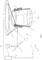
- Figure 1 shows an inspection device 1 for checking bottles 2 or similar containers.
- bottles 2 or similar containers are generally referred to as bottle 2.
- the bottle 2 can be made of a transparent or translucent material, preferably glass or a translucent material Plastic, for example PET.
- the material or the glass of the bottle can be blue, green or brown, to name just a few examples.
- the bottle 2 has a bottom and a side wall.
- a bottle mouth 3 is arranged opposite the floor.
- the bottle mouth 3 of the bottle 2 should preferably be cleaned, e.g. for contamination such as Rust deposits 4 are checked.
- the rust deposits 4 can originate from crown caps with which the bottle 2 was closed. Such rust deposits 4 preferably collect at a concave indentation 5 on the bottle neck.
- the inspection device 1 has at least one lighting unit 6 and at least one camera 7, the at least one lighting unit 6 being arranged above the bottle 2 to be inspected.
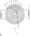
- the lighting unit 6 is designed as a light source board 6 ( Figure 2 ), whose light sources 8 emit changeable light in terms of color and / or their respective intensity, to a bottle color determined in the area of the bottle mouth 3, the light sources 8 being arranged concentrically around a center point of the light source circuit board 6 in radially spaced light source rings 9, and emitted light 10 is at least partially coupled into the interior of the bottle mouth wall.
- the lighting unit 6 or the light source board 6 is in Figure 2 shown more clearly.
- the concentric light source rings 9 with respective light sources 8 can be seen. Only eleven light source rings 9a to 9k (the designation is selected from the outside inwards) are arranged on the light source board 6 by way of example only. In the respective light source ring 9a to 9k, the neighboring light sources 8 are equally spaced, for example, as seen in the circumferential direction. As can be seen, the light source distances of the respective light source rings can be implemented differently. For example, the light source rings 9a to 9d and 9k and 9i have a smaller light source spacing than the light source rings 9e to 9h and 9j, which of course is only to be understood as exemplary and in no way restrictive.
- any light source spacing in the respective light source rings is conceivable. More or fewer than eleven light source rings 9 are also conceivable. Deviating from the ring-shaped arrangement of the light sources 8, any conceivable pattern with the light sources 8 can of course be arranged on the light source board 6. For example, a cross pattern is conceivable.
- the light source board 6 has connections 11 for a control and evaluation unit 12.
- the light sources 8 are preferably designed as LEDs, which can emit light of different colors and different intensities.
- the light sources 8 of the light source board 6 can be controlled via the control and evaluation unit 12.
- the light sources 8 of the individual light source rings 9 are advantageously controllable in a ring, in sections of a ring and / or individually. It is expediently possible to control the light sources 8 in such a way that light of adapted color and adapted intensity can be emitted by the lighting unit 6, the light to be emitted being adapted in particular to the respective glass color. In particular, it is possible to control the intensity of the light to be emitted differently at different areas of the light source board 6. Of course, such a control is possible that light patterns are emitted.
- emitted light 10 is coupled into the inner circumference of the bottle mouth 3 or the inner glass wall, the outer circumference of the area to be inspected being illuminated with light 19, which is likewise emitted from the lighting unit 6. It is favorable that, as mentioned above, different light intensities can be controlled, so that the outer circumference is only illuminated by the light 19, the light 10, which is directed and coupled in, can have a greater intensity. In this respect, the transmitted light inspection and the incident light illumination can be carried out with the invention and with a single lighting unit 6.
- a first optical element 13 can still be seen.
- the first optical element 13 depicts a peripheral section of the area to be inspected, so that a mirror image of the area to be inspected can be recorded by the camera 7.
- the camera 7 transmits the mirror image as actual data to the control and evaluation unit 12, which can also be referred to as control and evaluation unit 12, but is referred to below and previously only as control and evaluation unit 12.
- target data are stored which are comparable with the actual data received from the camera 7. Because the light emitted in its color components to the bottle color is adapted, it is expedient to carry out a comparison of the actual colors with the target colors in the control and evaluation unit 12. If deviations above specified limit values are detected, ie rust deposits 4 are detected, a discharge signal 14 is sent to a discharge station 15 which discharges the bottle 2 in question from the bottle flow.
- first optical elements 13 for example four first optical elements 13, each of which depict a different peripheral area, overlapping adjacent peripheral areas not being harmful.
- the four partial images are put together in the control and evaluation unit 12 to form an overall image, wherein, of course, an evaluation of the individual partial images is also conceivable.
- An embodiment is also conceivable in which the bottle 2 rotates, that is to say is inspected in a rotating manner, so that a circumferential arrangement of the first optical elements 13 is omitted and only a single optical element 13 can be sufficient.
- the light sources 8 each emit light of the same color space. It is therefore also sensible to design the camera 7 so that it is adapted to this color space.
- the light sources 8 can emit light of the RGB color space (red-green-blue), which is why the camera 7 should also be designed as an RGB camera. It is possible to assign a corresponding color filter 16 to the camera 7, which is shown in Figure 3 is indicated.
- the camera 7 is arranged with its optical axis X1 parallel to the bottle high pocket X2, but offset laterally to the latter.
- the camera 7 can be arranged above the bottle mouth 3.
- the camera 7 is closed in the exemplary embodiment Figure 3 with its optical axis X1 transversely, preferably perpendicular to the bottle vertical axis X2 above the bottle 2 to be inspected.
- Can be seen in Figure 3 also the four first optical elements 13, which each represent a different peripheral region of the region to be inspected.
- the camera 7 Since the camera 7 is arranged with its optical axis X1 transversely to the bottle vertical axis X2, the images which are recorded by the first optical elements 13 have to be deflected, which is done by means of the second and third optical elements 17 and 18 is reached. This need not be discussed in more detail.
- the lighting unit 6, that is to say the light source board 6, emits light adapted to the respective bottle color, that is to say color-modulated light, so that a reliable inspection can take place, for example, with regard to possible rust deposits 4.
- Wreath-wise connections of the light source rings 9 are conceivable, for example in order to achieve directed light.
- the transmitted light inspection, in which emitted, color-modulated light is coupled into the inner wall of the bottle mouth 3, is expedient, the transmitted light inspection being combinable with incident light illumination.
Landscapes
- Physics & Mathematics (AREA)
- General Physics & Mathematics (AREA)
- Biochemistry (AREA)
- Immunology (AREA)
- Health & Medical Sciences (AREA)
- Life Sciences & Earth Sciences (AREA)
- Chemical & Material Sciences (AREA)
- Analytical Chemistry (AREA)
- Pathology (AREA)
- General Health & Medical Sciences (AREA)
- Engineering & Computer Science (AREA)
- Theoretical Computer Science (AREA)
- Multimedia (AREA)
- Signal Processing (AREA)
- Mathematical Physics (AREA)
- Spectroscopy & Molecular Physics (AREA)
- Quality & Reliability (AREA)
- Computer Vision & Pattern Recognition (AREA)
- Investigating Materials By The Use Of Optical Means Adapted For Particular Applications (AREA)
Description
- Die Erfindung betrifft eine Inspektionsvorrichtung zum Kontrollieren von Flaschen oder dergleichen Behälter, umfassend zumindest eine Beleuchtungseinheit und zumindest eine Kamera, wobei die zumindest die Beleuchtungseinheit oberhalb der zu inspizierenden Flasche angeordnet ist. Die Erfindung betrifft aber auch ein Verfahren zur Leerflascheninspektion, insbesondere eines Mündungsbereiches der Flasche mit der Inspektionsvorrichtung.
- Derartige Flaschen oder dergleichen Behälter können für Flüssigkeiten, beispielsweise für Getränke verwendet werden. Die Behälter können aus einem transparenten oder transluzenten Material, beispielsweise aus Glas oder aus einem transluzenten Kunststoff, z.B. PET bestehen, Insbesondere Glasflaschen können unterschiedliche Färbungen aufweisen, wobei z.B. braune und grüne aber auch blaue Flaschenfarben lediglich beispielhaft erwähnt werden. Die Flaschen oder dergleichen Behälter werden im Leerzustand bevorzugt nach ihrer Reinigung auf einem Transporteur an der Inspektionsvorrichtung vorbeigeführt. Bekannt ist, dass Flaschen auch mit so genannten Kronkorken oder anderen oxidierbaren Verschlusselementen verschlossen werden können. Dabei ist es möglich, dass z.B. der Kronkorken oxidierte und sich so Rost des nicht mehr vorhandenen Kronkorkens oder des anderen oxidierbaren Verschlusselementes an dem Mündungsbereich der Flasehe abgelagert hat. Wird mit der Inspektionsvorrichtung abgelagerter Rost erkannt, obwohl die Leerflasche die Reinigungsvorrichtung passiert hat, wird die betreffende Flasche an geeigneter Stelle aus dem Flaschestrom ausgeschleust, und entweder vernichtet oder dem Flaschenstrom vor der Reinigungsanlage erneut zugeführt.
- Üblicherweise sendet die Beleuchtungseinheit ein Licht gleichen Spektrums, also in gleicher Farbe aus, weswegen die Inspektionseinrichtung bei Flaschen unterschiedlicher Farbegestaltung ein nicht immer gesichertes Inspektionsergebnis erzielt. So kann es sein, dass eine Flasche trotz noch vorhandener Rostablagerung die Inspektionsvorrichtung und die nach geschaltete Ausschleusvorrichtung als GUT-Flasche passiert, obwohl die betreffende Flasche aufgrund der vorhandenen Verschmutzung eigentlich aussortiert werden sollte. Gelangt eine solche in den weiteren Produktionsprozess, kann dies zu Produktausfällen führen, da das eingefüllte Produkt aus hygienischer Sicht aufgrund des möglichen Kontaktes mit der Verschmutzung nicht einwandfrei ist. Gelangt eine solche Flasche zum Verbraucher kann zudem ein erheblicher Schaden für den Hersteller des Produktes bzw. den Anlagehersteller entstehen.
- Aus der
US 2004/010815 A1 sind eine kontinuierlich arbeitende Vorrichtung und ein Verfahren zur Mündungsinspektion von Flaschen bekannt. Hierbei wird über einen oberen Beleuchtungsdom und einen tieferliegenden Beleuchtungskranz farblich unterschiedliches Licht gerichtet eingestrahlt, von einer Farbkamera erfasst und die Daten geeignet ausgewertet.US 7,477,374 B2 offenbart ebenfalls ein solches Inspektionssystem für Behältermündungen, wobei hier diffuses Licht einer Lichtquelle senkrecht von oben über geeignete Spiegel auf die Mündung geleitet wird. Dabei wird vorgeschlagen, die Mündung ggf. zeitgleich mit unterschiedlichem Licht, bspw. rot und grün anzublitzen und diese Lichtarten physikalisch durch die Spiegelanordnung voneinander zu trennen. Schließlich zeigt dieUS 7,911,602 B2 eine Inspektionsvorrichtung für Verschlüsse und zur Dekorerfassung, wobei auch hier vorgeschlagen wird, Licht mit unterschiedlichen Farben vorzusehen. Weiterhin ist aus derUS 2006/0126060 A1 eine Inspektionsvorrichtung für Behältermündungen bekannt, bei der radial beabstandete Lichtquellenringe jeweils konzentrisch um einen Mittelpunkt der Lichtquellenplatine angeordnet sind, wobei diese Lichtquellenringe kranzweise zugeschaltet werden können. - Der Erfindung liegt daher die Aufgabe zugrunde, eine Inspektionsvorrichtung, aber auch ein Inspektionsverfahren der Eingangs genannten Art mit einfachen Mitteln so zu verbessern, dass die vorgenannten Nachteile bei einer Inspektion der Behälter bzw. der Flaschen, insbesondere bei Flaschen unterschiedlicher Einfärbung vermieden sind.
- Erfindungsgemäß wird der vorrichtungstechnische Teil Aufgabe durch eine Inspektionsvorrichtung mit den Merkmalen des Anspruchs 1 gelöst, wobei die Lösung des verfahrenstechnischen Teils der Aufgabe mit einem Inspektionsverfahren mit den Merkmalen des Anspruchs 8 gelingt.
- Vorgeschlagen wird eine Inspektionsvorrichtung zum Kontrollieren von Flaschen oder dergleichen Behälter, umfassend zumindest eine Beleuchtungseinheit und zumindest eine Kamera, wobei die zumindest eine Beleuchtungseinheit oberhalb der zu inspizierenden Flasche angeordnet ist. Zielführend ist, dass die Beleuchtungseinheit als Lichtquellenplatine ausgeführt ist, deren Lichtquellen zumindest farblich und/oder in seiner jeweiligen Intensität, an eine im Bereich der Flaschenmündung festgestellte Flaschenfarbe, veränderbares Licht emittieren, wobei die Lichtquellen in radial beabstandeten Reihen, also in Lichtquellenringen jeweils konzentrisch um einen Mittelpunkt der Lichtquellenplatine angeordnet sind, und emittiertes Licht zumindest teilweise in das innere der Flaschenmündungswand eingekoppelt wird.|
- Zweckmäßiger Weise sind die Lichtquellen als LED ausgeführt, welche jeweils Licht eines gemeinsamen Lichtraumes emittieren. Beispielhaft können die LEDs Licht des RGB-Lichtraumes (Rot-Grün-Blau) emittieren, was natürlich nicht beschränkend sein soll.
- Günstig ist auch, wenn die Lichtquellenplatine eine Steuer- und Auswerteeinheit aufweist, bzw. mittels einer Steuer- und Auswerteeinheit angesteuert wird, so dass die einzelnen konzentrischen Reihen an Lichtquellen, also die einzelnen Lichtquellenringe ansteuerbar sind. Zweckmäßig ist auch, wenn zudem einzelne Lichtquellen einer jeweiligen konzentrischen Reihe, also im jeweiligen Lichtquellenring separat ansteuerbar sind. Mit dieser Maßnahme kann auf der Lichtquellenplatine ein jeweils gewünschtes und stets veränderbares Lichtmuster auch unterschiedlichster Intensität, insbesondere farbmoduliert erzeugt werden. Zweckmäßig ist, wenn die Beleuchtungseinheit, also die Lichtquellenplatine stroboskopisch angesteuert wird, also aufblitzt, bevorzugt farbmoduliert und/oder Intensitätsmoduliert aufblitzt, wenn eine zu inspizierende Flasche im Inspektionsbereich ist.
- Wie bereist erwähnt, wird ein Teil des emittierten Lichts in das innere der Flaschenmündungswand eingekoppelt. Ein anderer Teil des emittierten Lichts kann auf den Außenumfang der Flaschenmündung gerichtet sein, um diesem etwas aufzuhellen.
- Der Mündungsbereich der Flasche weist eine außenumfänglich angeordnete, konkave Einziehung unterhalb der Mündung auf, an welcher sich Rost bevorzugt ablagert. Zweckmäßig ist daher, wenn das emittierte Licht an einer solchen geeigneten Stelle des Innenumfangs der Flaschenmündung eingekoppelt wird, dass das Licht an dem zu inspizierenden Bereich wieder austritt, so dass also z.B. der konkaven Einziehung sicher inspizierbar ist. Zusätzlich sollte das auf den Außenumfang strahlende Licht ebenso gerichtet sein, um den zu inspizierenden Bereich, bevorzugt die konkave Einziehung zu erhellen.
- Wird das Licht in den Innenumfang des Flaschenmündungsbereiches, also von innen in die Mündungswand eingekoppelt, und tritt am Außenumfang wieder aus diesem aus, wird vorteilhaft eine Inspektion mit Durchlicht durchgeführt. Selbstverständlich wird das Licht in seinem Strahlengang entsprechend physikalischer Gesetze beim Eintritt in das Glasmaterial aber auch beim Austritt aus dem Glas gebrochen, was bei dem gerichteten Einkoppeln beachtet werden sollte, um den zu inspizierenden Bereich mit dem erforderlichen Licht durchleuchten zu können. Insofern wird die Lichtquellenplatine zudem gerichtetes Licht emittieren. Bei dem Vorgehen, den Mündungsbereich, bevorzugt die konkave Einziehung von außen zu erhellen, wird die Auflicht-Erhellung durchgeführt. Mit der Erfindung sind also Durchlicht und Auflicht gegebenenfalls kombinierbar.
- Zweckmäßig ist, wenn auch die zumindest eine Kamera oberhalb der zu inspizierenden Flasche angeordnet ist. Vorteilhaft im Sinne Erfindung ist auch, wenn die Kamera an den Farbraum der Lichtquellen angepasst ist, also z.B. einen Farbfilter aufweist, welcher an den Farbraum der Lichtquellen angepasst ist. Beispielsweise könnte die zumindest eine Kamera also auch als RGB-Kamera bezeichnet werden.
- Um den Flaschenmündungsbereich mit der oberhalb der Flasche angeordneten Kamera, auf Rostablagerungen inspizieren zu können ist es sinnvoll, wenn zumindest ein erstes, optisches Element vorgesehen wird, welches ein Abbild, bzw. Spiegelbild des Flaschenmündungsbereiches an die zumindest eine Kamera leitet. Das optische Element kann als Spiegel ausgeführt sein, und ist in jeweiliger Ausführung in der Inspektionstechnik von Leerflaschen allgemein bekannt. Die Kamera kann natürlich auch seitlich zur Flasche und/oder auf Flaschenhöhe und/oder unterhalb der Flasche angeordnet sein.
- Zielführend ist auch, wenn mehrere erste optische Elemente vorgesehen sind, um eine Rundumabbildung des Flaschenmündungsbereiches zu erhalten. Bevorzugt sind deshalb vier optische Elemente vorgesehen, welche jeweils einen bestimmten Flaschenmündungsabschnitt zur Kamera hin abbilden, wobei jeweils Überschneidungen jeweils benachbarter Abbildungen möglich sind. Die vier Teilabbildungen können in einer Auswerte- und Steuer- und Auswerteeinheit zusammengesetzt bzw. ausgewertet werden.
- Die Kamera kann mit ihrer optischen Achse bevorzugt quer, weiter bevorzugt senkrecht zur Flaschenhochachse angeordnet sein, so dass die Inspektionseinrichtung noch zusätzlich zu den ersten optischen Elementen zweite und dritte optische Elemente aufweisen kann, welche die genannten Abbildungen zur Kamera spiegeln.
- Mit der Erfindung werden so auch Rostablagerungen bzw. feine Rostflecken aufgrund der hochsensiblen Erfassung bzw. Auswertung detektierbar. Hierzu wird ein an die Flaschenfarbe angepasstes Licht, also farbmoduliertes Licht von den Lichtquellen emittiert, wobei in der Steuer- und Auswerteeinheit, welche wie erwähnt mit der Kamera in Verbindung steht, Soll-Daten, also Soll-Farben mit Ist-Daten, also mit Ist-Farben des Inspektionsbereiches verglichen bzw. ausgewertet werden. Die Soll-Daten sind in der Steuer- und Auswerteeinheit hinterlegt. Zusätzlich kann auch die modulierbare Lichtintensität im Inspektionsbereich gemessen werden. Zielführend ist aber auch, wenn die in konzentrischen Lichtquellenringen angeordneten Lichtquellen ringweise, ringabschnittsweise und/oder einzeln angesteuert werden, wobei auch eine farbvariabilität und eine jeweils gewünschte Lichtintensität steuerbar ist.
- Günstiger Weise wird bei der Erfindung also farblich und/oder auch in seiner Intensität angepasstes Durchlicht mit der Lichtraum-Kamera Erfassung kombiniert. Insbesondere wird die Lichtfarbe des zu emittierenden Lichtes an die Flaschenfarbe bzw. an die Glasfarbe angepasst. Beispielsweise wurde gefunden, dass Licht mit einem überwiegend grün/blauen Lichtanteil bei braunen Flaschen weniger geeignet ist, so dass das zu emittierende Licht in seinem Rotanteil erhöht wird, was die Transmission verbessert. Zweckmäßig ist also, zunächst die Glasfarbe zu detektieren, um mit dem Steuergerät die Lichtquellenplatine bzw. die einzelnen Lichtquellen so anzusteuern, dass jeweils das günstigste Inspektionslicht (farbmoduliert, intensitätsmoduliert, gerichtet zum korrekten Inneneinkoppeln) für die betreffende Glasfarbe emittiert wird.
- Selbstverständlich kann der Erfindungsgedanke mit dem sich anpassenden Licht auch an andere Inspektionsaufgaben übertragen werden, so dass die beispielhafte Rosterkennung nur beispielhaft, und keineswegs beschränkend sein soll.
- Weitere vorteilhafte Ausgestaltungen der Erfindung sind in den Unteransprüchen und der folgenden Figurenbeschreibung offenbart. Es zeigen
- Fig. 1
- einen prinzipiellen Aufbau der Inspektionsvorrichtung,
- Fg. 2
- eine vergrößerte Darstellung einer Beleuchtungseinheit, und
- Fig. 3
- eine erfindungsgemäße Inspektionsvorrichtung in Seitenansicht.
- In den unterschiedlichen Figuren sind gleiche Teile stets mit denselben Bezugszeichen versehen, weswegen diese in der Regel auch nur einmal beschrieben sind. In den
Figuren 1 und3 sind optische Strahlengänge der Spiegelbilder gestrichelt und nicht gesondert mit Bezugszeichen versehen. -
Figur 1 zeigt eine Inspektionsvorrichtung 1 zur Kontrolle von Flaschen 2 oder dergleichen Behälter. Im nachfolgenden werden Flaschen 2 oder dergleichen Behälter allgemein als Flasche 2 bezeichnet. Die Flasche 2 kann aus einem transparenten oder transluzenten Material, bevorzugt aus Glas oder aus einem transluzenten Kunststoff, z.B. PET bestehen. Das Material bzw. das Glas der Flasche kann z.B. blau, grün oder braun sein, um nur einige Beispiele zu nennen. - Die Flasche 2 weist einen Boden und eine Seitenwand auf. Gegenüberliegend zum Boden ist eine Flaschenmündung 3 angeordnet. Mit der Inspektionsvorrichtung 1 soll bevorzugt die Flaschenmündung 3 der Flasche 2 bevorzugt nach ihrer Reinigung z.B. auf Verschmutzungen wie z.B. Rostablagerungen 4 kontrolliert werden.
- Insofern kann auch von einer Leerflascheninspektion zur Rosterkennung gesprochen werden.
- Die Rostablagerungen 4 können von Kronkorken stammen, mit welchen die Flasche 2 verschlossen war. Derartige Rostablagerungen 4 sammeln sich bevorzugt an einer konkaven Einziehung 5 am Flaschenhals.
- Die Inspektionsvorrichtung 1 weist zumindest eine Beleuchtungseinheit 6 und zumindest eine Kamera 7 auf, wobei die zumindest eine Beleuchtungseinheit 6 oberhalb der zu inspizierenden Flasche 2 angeordnet ist. Die Beleuchtungseinheit 6 ist als Lichtquellenplatine 6 (
Figur 2 ) ausgeführt ist, deren Lichtquellen 8 farblich und/oder in seiner jeweiligen Intensität, an eine im Bereich der Flaschenmündung 3 festgestellte Flaschenfarbe, veränderbares Licht emittieren, wobei die Lichtquellen 8 in radial beabstandeten Lichtquellenringen 9 jeweils konzentrisch um einen Mittelpunkt der Lichtquellenplatine 6 angeordnet sind, und emittiertes Licht 10 zumindest teilweise in das innere der Flaschenmündungswand eingekoppelt wird. - Die Beleuchtungseinheit 6 bzw. die Lichtquellenplatine 6 ist in
Figur 2 deutlicher dargestellt. Erkennbar sind die konzentrischen Lichtquellenringe 9 mit jeweiligen Lichtquellen 8. Lediglich Beispielhaft sind elf Lichtquellenringe 9a bis 9k (Die Bezeichnung ist von außen nach innen gewählt) auf der Lichtquellenplatine 6 angeordnet. In dem jeweiligen Lichtquellenring 9a bis 9k sind die benachbarte Lichtquellen 8 in Umfangsrichtung gesehen beispielhaft jeweils gleich beabstandet. Wie erkennbar, sind die Lichtquellenabstände der jeweiligen Lichtquellenringe aber unterschiedlich ausführbar. Beispielsweise weisen die Lichtquellenringe 9a bis 9d und 9k und 9i einen kleineren Lichtquellenabstand auf als die Lichtquellenringe 9e bis 9h und 9j auf, was natürlich nur beispielhaft und keineswegs einschränkend zu verstehen ist. Denkbar sind jegliche Lichtquellenabstände in den jeweiligen Lichtquellenringen. Auch sind mehr oder weniger als elf Lichtquellenringe 9 denkbar. Abweichend von der ringweisen Anordnung der Lichtquellen 8, kann natürlich jedes erdenkliche Muster mit den Lichtquellen 8 auf der Lichtquellenplatine 6 angeordnet werden. Denkbar ist zum Beispiel ein Kreuzmuster. - Die Lichtquellenplatine 6 weist Anschlüsse 11 für eine Steuer- und Auswerteeinheit 12 auf. Die Lichtquellen 8 sind bevorzugt als LEDs ausgeführt, welche Licht unterschiedlicher Farbe und unterschiedlicher Intensität emittieren können. Über die Steuer- und Auswerteeinheit 12 sind die Lichtquellen 8 der Lichtquellenplatine 6 ansteuerbar. Vorteilhaft sind die Lichtquellen 8 der einzelnen Lichtquellenringe 9 ringweise, ringabschittsweise und/oder einzeln ansteuerbar. Günstiger Weise ist es möglich die Lichtquellen 8 so anzusteuern, dass Licht angepasster Farbe und angepasster Intensität von der Beleuchtungseinheit 6 emittierbar ist, wobei das zu emittierende Licht insbesondere an die jeweilige Glasfarbe angepasst ist. Insbesondere ist es möglich, die Intensität des zu emittierenden Lichtes an unterschiedlichen Bereichen der Lichtquellenplatine 6 unterschiedlich zu steuern. Möglich ist natürlich eine solche Ansteuerung, dass Lichtmuster emittiert werden.
- Wie in
Figur 1 erkennbar, wird emittiertes Licht 10 in den Innenumfang der Flaschenmündung 3 bzw. der inneren Glaswand eingekoppelt, wobei der Außenumfang des zu inspizierenden Bereiches mit Licht 19, welches ebenfalls aus der Beleuchtungseinheit 6 emittiert wird, angestrahlt wird. Günstig ist, dass hier, wie oben erwähnt, unterschiedliche Lichtintensitäten steuerbar sind, so dass der Außenumfang von dem Licht 19 lediglich erhellt wird, wobei das Licht 10, welches gerichtet ist und eingekoppelt wird eine größere Intensität haben kann. Insofern ist mit der Erfindung und mit einer einzigen Beleuchtungseinheit 6, die Durchlichtinspektion und die Auflichterhellung durchführbar. - In
Figur 3 ist noch ein erstes optisches Element 13 erkennbar. Das erste optische Element 13 bildet einen Umfangsabschnitt des zu inspizierenden Bereiches ab, so dass von der Kamera 7 ein Spiegelbild des zu inspizierenden Bereiches aufnehmbar ist. Die Kamera 7 leitet das Spiegelbild als Ist-Daten an die Steuer- und Auswerteeinheit 12, welche auch als Steuer- und Auswerteeinheit 12 bezeichnet werden kann, im Folgenden und zuvor aber lediglich als Steuer- und Auswerteeinheit 12 bezeichnet wird. In der Steuer- und Auswerteeinheit 12 bzw. in deren Auswerteteil sind Soll-Daten abgelegt, welche mit den von der Kamera 7 erhaltenen Ist-Daten vergleichbar sind. Da das emittierte Licht in seinen Farbanteilen an die Flaschenfarbe angepasst ist, ist zweckmäßig vorgesehen, in der Steuer- und Auswerteeinheit 12 einen Abgleich der Ist-Farben mit den Soll-Farben durchzuführen. Werden Abweichung oberhalb festgelegter Grenzwerte detektiert, also werden Rostablagerungen 4 detektiert, wird ein Ausschleussignal 14 an eine Ausschleusstation 15 geleitet, welche die betreffende Flasche 2 aus dem Flaschenstrom ausschleust. - Um ein umfängliches Abbild des zu inspizierenden Bereiches erreichen zu können, ist vorteilhaft vorgesehen, mehrere erste optische Elemente 13, beispielsweise vier erste optische Elemente 13 vorzusehen, welche jeweils einen anderen Umfangsbereich abbilden, wobei Überlappungen benachbarter Umfangsbereiche nicht schädlich sind. Die vier Teilabbildungen werden in der Steuer- und Auswerteeinheit 12 zu einem Gesamtbild zusammengesetzt, wobei natürlich auch eine Auswertung der jeweils einzelnen Teilabbildungen denkbar ist. Denkbar ist auch eine Ausgestaltung, bei welcher die Flasche 2 rotiert, also rotierend inspiziert wird, so dass eine umfangsmäßige Anordnung der ersten optischen Elemente 13 entfallen, und lediglich ein einziges optisches Element 13 ausreichend sein kann.
- Die Lichtquellen 8 emittieren jeweils Licht gleichen Farbraums. Sinnvoll ist daher auch die Kamera 7 so auszuführen, dass diese an diesen Farbraum angepasst ist. Beispielhaft können die Lichtquellen 8 Licht des RGB-Farbraums (Rot-Grün-Blau) emittieren, weshalb die Kamera 7 auch als RGB-Kamera ausgeführt sein sollte. Möglich ist die Zuordnung eines entsprechenden Farbfilters 16 zur Kamera 7, welcher in
Figur 3 angedeutet ist. - Wie in
Figur 1 erkennbar, ist die Kamera 7 mit ihrer optischen Achse X1 parallel zur Flaschenhochasche X2, aber seitlich zu dieser versetzt angeordnet. Die Kamera 7 kann oberhalb der Flaschenmündung 3 angeordnet sein. Im Unterschied dazu ist die Kamera 7 bei dem Ausführungsbeispiel zuFigur 3 mit ihrer optischen Achse X1 quer, bevorzugt senkrecht zur Flaschenhochachse X2 oberhalb der zu inspizierenden Flasche 2 angeordnet. Erkennbar sind inFigur 3 auch die vier ersten optischen Elemente 13, welche jeweils einen anderen Umfangsbereich des zu inspizierenden Bereiches abbilden. - Da die Kamera 7 mit ihrer optischen Achse X1 quer zur Flaschenhochachse X2 angeordnet ist, bedarf es einer Umlenkung der Abbildungen, welche von den ersten optischen Elementen 13 aufgenommen werden, was mittels zweiter und dritter optischer Elemente 17 und 18 erreicht wird. Hierauf braucht nicht näher eingegangen werden.
- Zielführend ist bei der Erfindung, dass die Beleuchtungseinheit 6, also die Lichtquellenplatine 6 an die jeweilige Flaschenfarbe angepasstes Licht, also farbmoduliertes Licht emittiert, so dass eine sichere Inspektion beispielsweise hinsichtlich möglicher Rostablagerungen 4 erfolgen kann. Denkbar sind kranzweise Zuschaltungen der Lichtquellenringe 9, um z.B. gerichtetes Licht zu erreichen. Sinnvoll ist die Durchlicht-Inspektion, in dem emittiertes, farbmoduliertes Licht in die Innenwand der Flaschenmündung 3 eingekoppelt wird, wobei die Durchlicht-Inspektion mit der Auflicht-Erhellung kombinierbar ist. Die physikalischen Brechungen des eintretenden und austretenden Lichts sind in
Figur 1 erkennbar, wobei das gerichtete, farbmodulierte Licht so einkoppelbar ist, dass ein Austritt am zu inspizierenden Bereich, also bevorzugt im bereich der konkaven Einziehung 5 sichergestellt ist. -
- 1
- Inspektionsvorrichtung
- 2
- Flasche
- 3
- Flaschenmündung
- 4
- Rostablagerung
- 5
- Konkave Einziehung
- 6
- Beleuchtungseinheit/Lichtquellenplatine
- 7
- Kamera
- 8
- Lichtquelle
- 9
- Lichtquellenringe
- 10
- Emittiertes, einzukoppelndes Licht
- 11
- Anschlüsse an 6
- 12
- Steuer- und Auswerteeinheit
- 13
- Erstes optisches Element
- 14
- Ausschleussignal
- 15
- Ausschleusstation
- 16
- Farbfilter
- 17
- Zweites optisches Element
- 18
- Drittes optisches Element
- 19
- Licht auf Außenumfang gerichtet
Claims (15)
- Inspektionsvorrichtung zum Kontrollieren von Flaschen (2) oder dergleichen Behälter, welche zumindest eine Beleuchtungseinheit (6) und zumindest eine Kamera (7) und eine Steuer- und Auswerteeinheit (12) aufweist, wobei zumindest die Beleuchtungseinheit (6) oberhalb einer zu inspizierenden Flasche (2) bzw. des Transportweges einer zu inspizierenden Flasche (2) angeordnet ist, wobei die Beleuchtungseinheit (6) als Lichtquellenplatine (6) ausgeführt ist, deren Lichtquellen (8) zumindest farblich, an eine im Bereich einer Flaschenmündung (3) festgestellte Flaschenfarbe, veränderbares Licht emittieren und die Kamera (7) eine farbsensitive Kamera ist, insbesondere eine RGB-Kamera, wobei die Lichtquellen (8) in radial beabstandeten Lichtquellenringen (9) jeweils konzentrisch um einen Mittelpunkt der Lichtquellenplatine (6) angeordnet sind, und emittiertes Licht zumindest teilweise in das Innere der Flaschenmündungswand einkoppelbar ist und wobei die Beleuchtungseinheit 6 derart ist, dass eine kranzweise Zuschaltung der Lichtquellenringe 9 erfolgen kann, dadurch gekennzeichnet, dass die Beleuchtungseinheit (6) in seiner Intensität veränderbares Licht emittiert.
- Inspektionsvorrichtung nach einem der vorhergehenden Ansprüche, dadurch gekennzeichnet, dass die Lichtquellen (8) als LEDs ausgeführt sind, aus welchen farbmoduliertes und/oder Intensitätsmoduliertes Licht gerichtet emittierbar ist.
- Inspektionsvorrichtung nach einem der vorhergehenden Ansprüche, dadurch gekennzeichnet, dass die Beleuchtungseinheit (6) eine Steuer- und Auswerteeinheit (12) zumindest zum Ansteuern der in Lichtquellenringen (9) angeordneten Lichtquellen (8) aufweist, wobei die Lichtquellen (8) einzeln oder in Gruppen stroboskopisch ansteuerbar sind.
- Inspektionsvorrichtung nach einem der vorhergehenden Ansprüche, dadurch gekennzeichnet, dass die Lichtquellen (8) in jeweiligen Lichtquellenringen (9) so angeordnet sind, dass benachbarte Lichtquellen (8) des betreffenden Lichtquellenringes (9) jeweils einen gleichen Abstand aufweisen.
- Inspektionsvorrichtung nach einem der vorhergehenden Ansprüche, dadurch gekennzeichnet, dass die Kamera (7) oberhalb der Flaschenmündung (3) angeordnet ist.
- Inspektionsvorrichtung nach einem der vorhergehenden Ansprüche, dadurch gekennzeichnet, dass zumindest ein erstes optisches Element (13) vorgesehen ist, welches ein Abbild des zu inspizierenden Bereiches zur Kamera (7) spiegelt.
- Inspektionsvorrichtung nach einem der vorhergehenden Ansprüche, dadurch gekennzeichnet, dass mehrere erste optische Elemente (13) vorgesehen sind, um eine Rundumabbildung zur Kamera (7) zu spiegeln.
- Verfahren zum Kontrollieren von Flaschen (2) oder dergleichen Behälter mit einer Inspektionsvorrichtung (1) nach einem der vorhergehenden Ansprüche, wobei die zumindest eine Beleuchtungseinheit (6) oberhalb der zu inspizierenden Flasche (2) angeordnet ist, wobei die Beleuchtungseinheit (6) von einer Steuer- und Auswerteeinheit (12) gesteuert zumindest farbmodulierbares Licht emittiert, wobei in einem ersten Schritt die Farbe bzw. die Farbmischung der Beleuchtungseinheit (6) bzw. der jeweiligen Lichtquellen (8) an die Farbe einer zu inspizierender Flasche (2) für eine maximale Lichttransmission angepasst wird, und wobei in mindestens einen nachfolgenden Schritt der Inspektion, das Licht durch die offene Mündung der Flasche (2) auf die innere Oberfläche der Flasche gerichtet ist und der austretende, transmittierte Anteil des Lichtes direkt oder indirekt mittels der mindestens einen Kamera (7) erfasst wird, dadurch gekennzeichnet, dass die Beleuchtungseinheit in seiner Intensität veränderbares Licht emittiert.
- Verfahren nach Anspruch 8, dadurch gekennzeichnet, dass der erste Schritt der Anpassung der Farbe bzw. der Farbmischung der Beleuchtungseinheit (6) bzw. der jeweiligen Lichtquellen (8) an die Farbe einer zu inspizierenden Flasche (2) oder Gruppe von Flaschen (2) einmalig vor einer von Inspektionsschritten vorgenommen wird.
- Verfahren nach Anspruch 8 oder 9, dadurch gekennzeichnet, dass die Beleuchtungseinheit (6) als Lichtquellenplatine (6) mit Lichtquellen (8) ausgeführt ist, die in Lichtquellenringen (9) angeordnet sind, wobei die Lichtquellen (8) von einer Steuer- und Auswerteeinheit (12) ansteuerbar sind, so dass farbmoduliertes und/oder intensitätsmoduliertes Licht gerichtet in einen Innenumfang einer Flaschenmündung (3) einkoppelbar ist.
- Verfahren nach einem der Ansprüche 8 bis 10, gekennzeichnet durch Lichtquellen (8) welche jeweils Licht gleichen Farbraumes emittieren.
- Verfahren nach einem der Ansprüche 8 bis 11, dadurch gekennzeichnet, dass der zu inspizierende Bereich mit Auflicht erhellt wird, wobei das Auflicht aus der Beleuchtungseinheit (6) emittiert wird.
- Verfahren nach einem der Ansprüche 8 bis 12, dadurch gekennzeichnet, dass die Beleuchtungseinheit (6) Lichtquellenringe (9) mit Lichtquellen (8) aufweist, welche ringweise, ringabschnittsweise und/oder einzeln mit der Steuer- und Auswerteeinheit (12) ansteuerbar sind und/oder , die Lichtquellen (8) einzeln oder in Gruppen stroboskopisch ansteuerbar sind.
- Verfahren nach einem der Ansprüche 8 bis 13 umfassend die Schritte:a. Erkennen einer Flaschenfarbe,b. Ansteuern der auf der Beleuchtungseinheit (6) angeordneten Lichtquellen (8) so, dass an die detektierte Flaschenfarbe angepasst farbmoduliertes Licht emittiert wird,c. Abbilden des zu inspizierenden Bereiches der Flasche (2) in der Kamera (7) unter Zwischenschaltung von zumindest ersten optischen Elementen (13) als Ist-Daten,d. Weiterleiten der Ist-Daten zu der Steuer- und Auswerteeinheit (12) in welcher Soll-Daten abgelegt sind,e. Auswerten und Vergleichen der Ist-Daten mit den Soll-Daten in der Steuer- und Auswerteeinheit, undf. Generieren eines Ausschleussignals wenn eine Abweichung der Ist-Daten zu den Soll-Daten einen vorgebbaren Grenzwert überschreitet.
- Verfahren nach Anspruch 14, dadurch gekennzeichnet, dass in der Steuer- und Auswerteeinheit ein Abgleich zwischen Ist-Farben und Soll-Farben durchgeführt wird, insbesondere zur Detektion von Rostanhaftungen an der Flaschenaußenseite, um gegebenenfalls das Ausschleussignal oder ein sonstiges Steuersignal zu generieren.
Applications Claiming Priority (2)
| Application Number | Priority Date | Filing Date | Title |
|---|---|---|---|
| DE102011106136A DE102011106136A1 (de) | 2011-06-10 | 2011-06-10 | Leerflascheninspektion |
| PCT/EP2012/001895 WO2012167860A1 (de) | 2011-06-10 | 2012-05-02 | Leerflascheninspektion |
Publications (2)
| Publication Number | Publication Date |
|---|---|
| EP2718696A1 EP2718696A1 (de) | 2014-04-16 |
| EP2718696B1 true EP2718696B1 (de) | 2020-01-08 |
Family
ID=46025613
Family Applications (1)
| Application Number | Title | Priority Date | Filing Date |
|---|---|---|---|
| EP12718087.5A Active EP2718696B1 (de) | 2011-06-10 | 2012-05-02 | Leerflascheninspektion |
Country Status (9)
| Country | Link |
|---|---|
| US (1) | US9535011B2 (de) |
| EP (1) | EP2718696B1 (de) |
| JP (1) | JP6017549B2 (de) |
| CN (1) | CN103718026B (de) |
| BR (1) | BR112013030144B1 (de) |
| DE (1) | DE102011106136A1 (de) |
| MX (1) | MX2013014227A (de) |
| RU (1) | RU2552122C1 (de) |
| WO (1) | WO2012167860A1 (de) |
Families Citing this family (14)
| Publication number | Priority date | Publication date | Assignee | Title |
|---|---|---|---|---|
| FR3005354B1 (fr) * | 2013-05-03 | 2015-05-15 | Msc & Sgcc | Procede et dispositif d'observation et d'analyse de singularites optiques portees par des recipients en verre |
| DE102014100699A1 (de) * | 2014-01-22 | 2015-07-23 | Krones Ag | Vorrichtung zur optischen Inspektion von Verpackungsgegenständen in der Getränketechnologie |
| CN103803125A (zh) * | 2014-02-24 | 2014-05-21 | 江苏新美星包装机械股份有限公司 | 饮料生产线中的led灯检装置 |
| DE102014118619A1 (de) * | 2014-12-15 | 2016-06-16 | Endress + Hauser Conducta Gesellschaft für Mess- und Regeltechnik mbH + Co. KG | Vorrichtung und Verfahren zur Ermittlung und/oder Überwachung einer Oberflächeneigenschaft einer medienberührenden Oberfläche |
| CN105241888B (zh) * | 2015-09-25 | 2018-11-02 | 上海金啤包装检测科技有限公司 | 一种瓶口缺陷的检测方法及检测装置 |
| DE102016209716A1 (de) * | 2016-06-02 | 2017-12-07 | Robert Bosch Gmbh | Vorrichtung und Verfahren zur Inspektion von Behältnissen |
| DE102017008406C5 (de) * | 2017-09-07 | 2026-04-02 | Heuft Systemtechnik Gmbh | Inspektionsvorrichtung und ein Verfahren mit Farbbeleuchtung |
| DE102017123684A1 (de) * | 2017-10-11 | 2019-04-11 | Krones Ag | Vorrichtung zum Inspizieren von Behältnissen und insbesondere von Dosen |
| CN108195846B (zh) * | 2017-12-26 | 2020-09-25 | 成都睿视智能设备有限责任公司 | 一种检测塑料容器的图像采集系统 |
| CN108226175B (zh) * | 2017-12-26 | 2020-09-25 | 成都睿视智能设备有限责任公司 | 一种塑料容器检测系统及检测方法 |
| DE102019117260A1 (de) * | 2019-06-26 | 2020-12-31 | Seidenader Maschinenbau Gmbh | Vorrichtung zur optischen Inspektion von leeren und mit Flüssigkeit gefüllten Behältern |
| FR3113131B1 (fr) * | 2020-07-29 | 2023-03-31 | Tiama | Dispositif et procédé d'inspection en transmission de récipients comportant au moins une source de lumière à diode électroluminescente |
| CN113305034B (zh) * | 2020-09-14 | 2023-05-09 | 绵阳中润机电科技有限公司 | 回收瓶的视觉分级系统及方法 |
| CN119510432B (zh) * | 2024-11-25 | 2025-09-19 | 湖北劲华玻璃有限公司 | 一种玻璃酒瓶双口瓶口检测装置及其检测方法 |
Citations (1)
| Publication number | Priority date | Publication date | Assignee | Title |
|---|---|---|---|---|
| US20060126060A1 (en) * | 2002-10-25 | 2006-06-15 | Olivier Colle | Lighting method and device for detection of surface defects and/or unfilled finish on the finish of a container |
Family Cites Families (33)
| Publication number | Priority date | Publication date | Assignee | Title |
|---|---|---|---|---|
| US3191773A (en) * | 1960-04-11 | 1965-06-29 | Barry Wehmiller Machinery Co | Bottle-cleanliness inspection apparatus |
| US4731649A (en) * | 1986-09-11 | 1988-03-15 | Vistech Corp. | Oblique illumination for video rim inspection |
| NL8800866A (nl) * | 1988-04-05 | 1989-11-01 | Thomassen & Drijver | Inspektie-inrichting. |
| DE69015286T2 (de) * | 1989-09-08 | 1995-08-10 | Kirin Techno Syst Yokohama | Verfahren und Gerät zum Nachweisen von Fremdkörpern. |
| RU2017142C1 (ru) * | 1991-01-14 | 1994-07-30 | Московский институт теплотехники | Устройство для контроля чистоты пустых прозрачных сосудов |
| EP0657732A1 (de) * | 1993-12-06 | 1995-06-14 | Elpatronic Ag | Verfahren und Vorrichtung zur optischen Prüfung eines durchsichtigen Behälterbereichs, insbesondere des Mündungsbereichs |
| DE19514271C2 (de) * | 1995-04-21 | 1999-08-26 | Kettner Gmbh | Vorrichtung zum Überprüfen von Flaschen auf Beschädigung |
| DE29706425U1 (de) * | 1997-04-10 | 1998-08-06 | Heuft Systemtechnik Gmbh, 56659 Burgbrohl | Vorrichtung zum Erkennen von diffus streuenden Verunreinigungen in transparenten Behältern |
| US6175107B1 (en) * | 1998-05-27 | 2001-01-16 | Owens-Brockway Glass Container Inc. | Inspection of containers employing a single area array sensor and alternately strobed light sources |
| DE29907762U1 (de) | 1999-04-27 | 1999-10-21 | Horst, Michael, Dipl.-Ing., 34128 Kassel | Vorrichtung zur Untersuchung eines Behälters auf Oberflächenfehler |
| DE19953738C1 (de) * | 1999-11-09 | 2001-06-07 | Krones Ag | Inspektionsvorrichtung zur Seitenwandkontrolle von Gefäßen |
| US6104482A (en) * | 1999-12-02 | 2000-08-15 | Owens-Brockway Glass Container Inc. | Container finish check detection |
| JP2001221747A (ja) * | 2000-02-03 | 2001-08-17 | Suntory Ltd | 液体充填用容器の撮像方法および装置 |
| JP2001229381A (ja) * | 2000-02-15 | 2001-08-24 | Matsushita Electric Works Ltd | 画像処理検査システムおよびその方法 |
| JP2004045273A (ja) * | 2002-07-12 | 2004-02-12 | Asahi Breweries Ltd | 検査装置 |
| DE60225354T2 (de) * | 2002-10-18 | 2009-02-19 | Kirin Techno-System Corp., Yokohama | Verfahren und vorrichtung zur herstellung eines referenzbildes bei einer prüfvorrichtung für glasflaschen |
| EP1560017B1 (de) * | 2002-10-18 | 2009-08-05 | Kirin Techno-System Company, Limited | Prüfvorrichtung für glasflaschen |
| JP4743552B2 (ja) * | 2002-12-27 | 2011-08-10 | キリンテクノシステム株式会社 | 異物検査方法、及び異物検査装置並びに異物検査用の照明装置 |
| US20040150815A1 (en) * | 2003-02-05 | 2004-08-05 | Applied Vision Company, Llc | Flaw detection in objects and surfaces |
| WO2005103605A1 (en) * | 2004-04-22 | 2005-11-03 | Opo Sprl | Instrument for measuring the thickness of a coating on bottles |
| DE102005001810B3 (de) * | 2005-01-13 | 2006-06-22 | Heye International Gmbh | Verfahren und Vorrichtung zum Prüfen einer Dichtfläche einer Behältermündung |
| NL1031853C2 (nl) * | 2006-05-22 | 2007-11-23 | Eagle Vision Systems B V | Werkwijze en inrichting voor het detecteren van een ongewenst object of defect. |
| US7626158B2 (en) * | 2006-10-23 | 2009-12-01 | Emhart Glass S.A. | Machine for inspecting glass containers |
| US7541572B2 (en) * | 2006-10-23 | 2009-06-02 | Emhart Glass S.A. | Machine for inspecting rotating glass containers with light source triggered multiple times during camera exposure time |
| DE102007018870A1 (de) * | 2007-04-19 | 2008-10-23 | Krones Ag | Inspektionsvorrichtung zum Untersuchen von Behältnisverschlüssen |
| CN101063662A (zh) * | 2007-05-15 | 2007-10-31 | 广州市万世德包装机械有限公司 | 空瓶瓶底缺陷的检测方法及基于dsp的空瓶瓶底缺陷检测装置 |
| DE102008037727A1 (de) * | 2008-08-14 | 2010-03-04 | Khs Ag | Leerflascheninspektion |
| US8284305B2 (en) * | 2008-11-26 | 2012-10-09 | Parata Systems, Llc | System and method for acquiring images |
| DE102009040626A1 (de) * | 2009-09-08 | 2011-03-10 | Krones Ag | Verfahren und Vorrichtung zur Bestimmung der Masse und/oder eines Massenanteils eines Wandabschnitts einer Kunststoffflasche |
| US8477989B2 (en) * | 2010-01-14 | 2013-07-02 | Parata Systems, Llc | Method of taking an image of an object residing in a transparent, colored container |
| CN201689057U (zh) * | 2010-05-13 | 2010-12-29 | 山东大学 | 基于客户机-服务器的智能空瓶检测机 |
| CN101819162A (zh) * | 2010-05-13 | 2010-09-01 | 山东大学 | 空瓶瓶壁缺陷检测方法及装置 |
| CN101858768B (zh) * | 2010-05-14 | 2012-05-16 | 山东大学 | 一种饮料灌装后液位检测装置及方法 |
-
2011
- 2011-06-10 DE DE102011106136A patent/DE102011106136A1/de not_active Ceased
-
2012
- 2012-05-02 EP EP12718087.5A patent/EP2718696B1/de active Active
- 2012-05-02 WO PCT/EP2012/001895 patent/WO2012167860A1/de not_active Ceased
- 2012-05-02 JP JP2014513925A patent/JP6017549B2/ja not_active Expired - Fee Related
- 2012-05-02 CN CN201280028525.5A patent/CN103718026B/zh active Active
- 2012-05-02 BR BR112013030144-9A patent/BR112013030144B1/pt active IP Right Grant
- 2012-05-02 US US14/125,180 patent/US9535011B2/en active Active
- 2012-05-02 RU RU2013157117/28A patent/RU2552122C1/ru active
- 2012-05-02 MX MX2013014227A patent/MX2013014227A/es active IP Right Grant
Patent Citations (1)
| Publication number | Priority date | Publication date | Assignee | Title |
|---|---|---|---|---|
| US20060126060A1 (en) * | 2002-10-25 | 2006-06-15 | Olivier Colle | Lighting method and device for detection of surface defects and/or unfilled finish on the finish of a container |
Also Published As
| Publication number | Publication date |
|---|---|
| MX2013014227A (es) | 2014-01-23 |
| US9535011B2 (en) | 2017-01-03 |
| JP6017549B2 (ja) | 2016-11-02 |
| DE102011106136A1 (de) | 2012-12-13 |
| JP2014516161A (ja) | 2014-07-07 |
| EP2718696A1 (de) | 2014-04-16 |
| BR112013030144A2 (pt) | 2016-09-27 |
| CN103718026B (zh) | 2017-10-10 |
| BR112013030144B1 (pt) | 2020-03-24 |
| US20140226005A1 (en) | 2014-08-14 |
| WO2012167860A1 (de) | 2012-12-13 |
| CN103718026A (zh) | 2014-04-09 |
| RU2552122C1 (ru) | 2015-06-10 |
Similar Documents
| Publication | Publication Date | Title |
|---|---|---|
| WO2012167860A1 (de) | Leerflascheninspektion | |
| EP2638385B1 (de) | Verfahren zur funktionskontrolle einer inspektionsvorrichtung und vorrichtung zur inspektion eines produktstroms | |
| EP3679356B1 (de) | Inspektionsvorrichtung mit farbbeleuchtung | |
| EP2290355B1 (de) | Vorrichtung und Verfahren zum Inspizieren etikettierter Gefäße | |
| DE3940693C1 (de) | ||
| EP2089168B1 (de) | Vorrichtung und verfarhen zur optischen sortierung von schüttgut | |
| EP2596340B1 (de) | Erfassungssystem zur flaschennaht- und embossingausrichtung und verfahren zur behandlung von flaschen. | |
| DE102010012570B4 (de) | Vorrichtung und Verfahren zum Untersuchen von befüllten Behältnissen auf Fremdkörper | |
| DE102012009783B3 (de) | Verfahren und Vorrichtung zur Inspektion von Leerflaschen | |
| EP2450696B1 (de) | Vorrichtung und Verfahren zum Inspizieren von Behältnissen | |
| EP2547591B1 (de) | Deckelsichttulpe | |
| DE10065290C2 (de) | Verfahren und Vorrichtung zur optischen Inspektion von Flaschen | |
| EP3812748B1 (de) | Verfahren und vorrichtung zur optischen inspektion von behältern | |
| DE102019208295A1 (de) | Verfahren und Vorrichtung zur optischen Inspektion von Behältern | |
| DE3111194C2 (de) | Verfahren und Vorrichtung zur Feststellung von Fehlern von Glasgegenständen | |
| WO2018041902A1 (de) | Vorrichtung zum detektieren von objekten in einem materialstrom | |
| EP2442080B1 (de) | Vorrichtung und Verfahren zur Inspektion von Behältern | |
| EP1681559B1 (de) | Verfahren und Vorrichtung zum Prüfen einer Dichtfläche einer Behältermündung | |
| EP2671649B2 (de) | Vorrichtung zur Identifizierung einer Flasche | |
| EP4473297A1 (de) | Inspektionsvorrichtung mit mehr-kanal-detektionseinheit | |
| DE29907762U1 (de) | Vorrichtung zur Untersuchung eines Behälters auf Oberflächenfehler | |
| DE102015115862A1 (de) | Vorrichtung und Verfahren zum Inspizieren von Behältnisverschlüssen | |
| DE202012104043U1 (de) | Inspektionsvorrichtung für Behältnismündungen | |
| DE102009036389A1 (de) | Verfahren und Vorrichtung zur Überprüfung von mit Gefäßen bestückten oder bestückbaren, oben offenen Aufnahmebehältern | |
| DE102007031749A1 (de) | Erkennungssystem für Markierungen im Schulter- und Halsbereich von Flaschen |
Legal Events
| Date | Code | Title | Description |
|---|---|---|---|
| PUAI | Public reference made under article 153(3) epc to a published international application that has entered the european phase |
Free format text: ORIGINAL CODE: 0009012 |
|
| 17P | Request for examination filed |
Effective date: 20140110 |
|
| AK | Designated contracting states |
Kind code of ref document: A1 Designated state(s): AL AT BE BG CH CY CZ DE DK EE ES FI FR GB GR HR HU IE IS IT LI LT LU LV MC MK MT NL NO PL PT RO RS SE SI SK SM TR |
|
| DAX | Request for extension of the european patent (deleted) | ||
| STAA | Information on the status of an ep patent application or granted ep patent |
Free format text: STATUS: EXAMINATION IS IN PROGRESS |
|
| 17Q | First examination report despatched |
Effective date: 20180627 |
|
| GRAP | Despatch of communication of intention to grant a patent |
Free format text: ORIGINAL CODE: EPIDOSNIGR1 |
|
| STAA | Information on the status of an ep patent application or granted ep patent |
Free format text: STATUS: GRANT OF PATENT IS INTENDED |
|
| INTG | Intention to grant announced |
Effective date: 20191009 |
|
| RAP1 | Party data changed (applicant data changed or rights of an application transferred) |
Owner name: KHS GMBH |
|
| GRAS | Grant fee paid |
Free format text: ORIGINAL CODE: EPIDOSNIGR3 |
|
| GRAA | (expected) grant |
Free format text: ORIGINAL CODE: 0009210 |
|
| STAA | Information on the status of an ep patent application or granted ep patent |
Free format text: STATUS: THE PATENT HAS BEEN GRANTED |
|
| AK | Designated contracting states |
Kind code of ref document: B1 Designated state(s): AL AT BE BG CH CY CZ DE DK EE ES FI FR GB GR HR HU IE IS IT LI LT LU LV MC MK MT NL NO PL PT RO RS SE SI SK SM TR |
|
| REG | Reference to a national code |
Ref country code: GB Ref legal event code: FG4D Free format text: NOT ENGLISH |
|
| REG | Reference to a national code |
Ref country code: CH Ref legal event code: EP |
|
| REG | Reference to a national code |
Ref country code: DE Ref legal event code: R096 Ref document number: 502012015687 Country of ref document: DE |
|
| REG | Reference to a national code |
Ref country code: IE Ref legal event code: FG4D Free format text: LANGUAGE OF EP DOCUMENT: GERMAN |
|
| REG | Reference to a national code |
Ref country code: AT Ref legal event code: REF Ref document number: 1223314 Country of ref document: AT Kind code of ref document: T Effective date: 20200215 |
|
| REG | Reference to a national code |
Ref country code: NL Ref legal event code: MP Effective date: 20200108 |
|
| REG | Reference to a national code |
Ref country code: LT Ref legal event code: MG4D |
|
| PG25 | Lapsed in a contracting state [announced via postgrant information from national office to epo] |
Ref country code: PT Free format text: LAPSE BECAUSE OF FAILURE TO SUBMIT A TRANSLATION OF THE DESCRIPTION OR TO PAY THE FEE WITHIN THE PRESCRIBED TIME-LIMIT Effective date: 20200531 Ref country code: FI Free format text: LAPSE BECAUSE OF FAILURE TO SUBMIT A TRANSLATION OF THE DESCRIPTION OR TO PAY THE FEE WITHIN THE PRESCRIBED TIME-LIMIT Effective date: 20200108 Ref country code: RS Free format text: LAPSE BECAUSE OF FAILURE TO SUBMIT A TRANSLATION OF THE DESCRIPTION OR TO PAY THE FEE WITHIN THE PRESCRIBED TIME-LIMIT Effective date: 20200108 Ref country code: LT Free format text: LAPSE BECAUSE OF FAILURE TO SUBMIT A TRANSLATION OF THE DESCRIPTION OR TO PAY THE FEE WITHIN THE PRESCRIBED TIME-LIMIT Effective date: 20200108 Ref country code: NL Free format text: LAPSE BECAUSE OF FAILURE TO SUBMIT A TRANSLATION OF THE DESCRIPTION OR TO PAY THE FEE WITHIN THE PRESCRIBED TIME-LIMIT Effective date: 20200108 Ref country code: NO Free format text: LAPSE BECAUSE OF FAILURE TO SUBMIT A TRANSLATION OF THE DESCRIPTION OR TO PAY THE FEE WITHIN THE PRESCRIBED TIME-LIMIT Effective date: 20200408 |
|
| PG25 | Lapsed in a contracting state [announced via postgrant information from national office to epo] |
Ref country code: IS Free format text: LAPSE BECAUSE OF FAILURE TO SUBMIT A TRANSLATION OF THE DESCRIPTION OR TO PAY THE FEE WITHIN THE PRESCRIBED TIME-LIMIT Effective date: 20200508 Ref country code: BG Free format text: LAPSE BECAUSE OF FAILURE TO SUBMIT A TRANSLATION OF THE DESCRIPTION OR TO PAY THE FEE WITHIN THE PRESCRIBED TIME-LIMIT Effective date: 20200408 Ref country code: SE Free format text: LAPSE BECAUSE OF FAILURE TO SUBMIT A TRANSLATION OF THE DESCRIPTION OR TO PAY THE FEE WITHIN THE PRESCRIBED TIME-LIMIT Effective date: 20200108 Ref country code: LV Free format text: LAPSE BECAUSE OF FAILURE TO SUBMIT A TRANSLATION OF THE DESCRIPTION OR TO PAY THE FEE WITHIN THE PRESCRIBED TIME-LIMIT Effective date: 20200108 Ref country code: GR Free format text: LAPSE BECAUSE OF FAILURE TO SUBMIT A TRANSLATION OF THE DESCRIPTION OR TO PAY THE FEE WITHIN THE PRESCRIBED TIME-LIMIT Effective date: 20200409 Ref country code: HR Free format text: LAPSE BECAUSE OF FAILURE TO SUBMIT A TRANSLATION OF THE DESCRIPTION OR TO PAY THE FEE WITHIN THE PRESCRIBED TIME-LIMIT Effective date: 20200108 |
|
| REG | Reference to a national code |
Ref country code: DE Ref legal event code: R097 Ref document number: 502012015687 Country of ref document: DE |
|
| PG25 | Lapsed in a contracting state [announced via postgrant information from national office to epo] |
Ref country code: DK Free format text: LAPSE BECAUSE OF FAILURE TO SUBMIT A TRANSLATION OF THE DESCRIPTION OR TO PAY THE FEE WITHIN THE PRESCRIBED TIME-LIMIT Effective date: 20200108 Ref country code: SK Free format text: LAPSE BECAUSE OF FAILURE TO SUBMIT A TRANSLATION OF THE DESCRIPTION OR TO PAY THE FEE WITHIN THE PRESCRIBED TIME-LIMIT Effective date: 20200108 Ref country code: SM Free format text: LAPSE BECAUSE OF FAILURE TO SUBMIT A TRANSLATION OF THE DESCRIPTION OR TO PAY THE FEE WITHIN THE PRESCRIBED TIME-LIMIT Effective date: 20200108 Ref country code: EE Free format text: LAPSE BECAUSE OF FAILURE TO SUBMIT A TRANSLATION OF THE DESCRIPTION OR TO PAY THE FEE WITHIN THE PRESCRIBED TIME-LIMIT Effective date: 20200108 Ref country code: ES Free format text: LAPSE BECAUSE OF FAILURE TO SUBMIT A TRANSLATION OF THE DESCRIPTION OR TO PAY THE FEE WITHIN THE PRESCRIBED TIME-LIMIT Effective date: 20200108 Ref country code: RO Free format text: LAPSE BECAUSE OF FAILURE TO SUBMIT A TRANSLATION OF THE DESCRIPTION OR TO PAY THE FEE WITHIN THE PRESCRIBED TIME-LIMIT Effective date: 20200108 Ref country code: CZ Free format text: LAPSE BECAUSE OF FAILURE TO SUBMIT A TRANSLATION OF THE DESCRIPTION OR TO PAY THE FEE WITHIN THE PRESCRIBED TIME-LIMIT Effective date: 20200108 |
|
| PLBE | No opposition filed within time limit |
Free format text: ORIGINAL CODE: 0009261 |
|
| STAA | Information on the status of an ep patent application or granted ep patent |
Free format text: STATUS: NO OPPOSITION FILED WITHIN TIME LIMIT |
|
| 26N | No opposition filed |
Effective date: 20201009 |
|
| PG25 | Lapsed in a contracting state [announced via postgrant information from national office to epo] |
Ref country code: LI Free format text: LAPSE BECAUSE OF NON-PAYMENT OF DUE FEES Effective date: 20200531 Ref country code: CH Free format text: LAPSE BECAUSE OF NON-PAYMENT OF DUE FEES Effective date: 20200531 Ref country code: MC Free format text: LAPSE BECAUSE OF FAILURE TO SUBMIT A TRANSLATION OF THE DESCRIPTION OR TO PAY THE FEE WITHIN THE PRESCRIBED TIME-LIMIT Effective date: 20200108 |
|
| PG25 | Lapsed in a contracting state [announced via postgrant information from national office to epo] |
Ref country code: SI Free format text: LAPSE BECAUSE OF FAILURE TO SUBMIT A TRANSLATION OF THE DESCRIPTION OR TO PAY THE FEE WITHIN THE PRESCRIBED TIME-LIMIT Effective date: 20200108 Ref country code: PL Free format text: LAPSE BECAUSE OF FAILURE TO SUBMIT A TRANSLATION OF THE DESCRIPTION OR TO PAY THE FEE WITHIN THE PRESCRIBED TIME-LIMIT Effective date: 20200108 |
|
| REG | Reference to a national code |
Ref country code: BE Ref legal event code: MM Effective date: 20200531 |
|
| GBPC | Gb: european patent ceased through non-payment of renewal fee |
Effective date: 20200502 |
|
| PG25 | Lapsed in a contracting state [announced via postgrant information from national office to epo] |
Ref country code: LU Free format text: LAPSE BECAUSE OF NON-PAYMENT OF DUE FEES Effective date: 20200502 |
|
| PG25 | Lapsed in a contracting state [announced via postgrant information from national office to epo] |
Ref country code: IE Free format text: LAPSE BECAUSE OF NON-PAYMENT OF DUE FEES Effective date: 20200502 Ref country code: GB Free format text: LAPSE BECAUSE OF NON-PAYMENT OF DUE FEES Effective date: 20200502 |
|
| PG25 | Lapsed in a contracting state [announced via postgrant information from national office to epo] |
Ref country code: BE Free format text: LAPSE BECAUSE OF NON-PAYMENT OF DUE FEES Effective date: 20200531 |
|
| PG25 | Lapsed in a contracting state [announced via postgrant information from national office to epo] |
Ref country code: TR Free format text: LAPSE BECAUSE OF FAILURE TO SUBMIT A TRANSLATION OF THE DESCRIPTION OR TO PAY THE FEE WITHIN THE PRESCRIBED TIME-LIMIT Effective date: 20200108 Ref country code: MT Free format text: LAPSE BECAUSE OF FAILURE TO SUBMIT A TRANSLATION OF THE DESCRIPTION OR TO PAY THE FEE WITHIN THE PRESCRIBED TIME-LIMIT Effective date: 20200108 Ref country code: CY Free format text: LAPSE BECAUSE OF FAILURE TO SUBMIT A TRANSLATION OF THE DESCRIPTION OR TO PAY THE FEE WITHIN THE PRESCRIBED TIME-LIMIT Effective date: 20200108 |
|
| PG25 | Lapsed in a contracting state [announced via postgrant information from national office to epo] |
Ref country code: MK Free format text: LAPSE BECAUSE OF FAILURE TO SUBMIT A TRANSLATION OF THE DESCRIPTION OR TO PAY THE FEE WITHIN THE PRESCRIBED TIME-LIMIT Effective date: 20200108 Ref country code: AL Free format text: LAPSE BECAUSE OF FAILURE TO SUBMIT A TRANSLATION OF THE DESCRIPTION OR TO PAY THE FEE WITHIN THE PRESCRIBED TIME-LIMIT Effective date: 20200108 |
|
| PGFP | Annual fee paid to national office [announced via postgrant information from national office to epo] |
Ref country code: AT Payment date: 20250522 Year of fee payment: 14 |
|
| P01 | Opt-out of the competence of the unified patent court (upc) registered |
Free format text: CASE NUMBER: UPC_APP_0014579_2718696/2025 Effective date: 20251125 |
|
| PGFP | Annual fee paid to national office [announced via postgrant information from national office to epo] |
Ref country code: IT Payment date: 20260525 Year of fee payment: 15 |
|
| PGFP | Annual fee paid to national office [announced via postgrant information from national office to epo] |
Ref country code: DE Payment date: 20260522 Year of fee payment: 15 |
|
| PGFP | Annual fee paid to national office [announced via postgrant information from national office to epo] |
Ref country code: FR Payment date: 20260526 Year of fee payment: 15 |