EP2716819A1 - Mastanordnung - Google Patents
Mastanordnung Download PDFInfo
- Publication number
- EP2716819A1 EP2716819A1 EP13187002.4A EP13187002A EP2716819A1 EP 2716819 A1 EP2716819 A1 EP 2716819A1 EP 13187002 A EP13187002 A EP 13187002A EP 2716819 A1 EP2716819 A1 EP 2716819A1
- Authority
- EP
- European Patent Office
- Prior art keywords
- mast
- foundation
- flange plate
- arrangement according
- region
- Prior art date
- Legal status (The legal status is an assumption and is not a legal conclusion. Google has not performed a legal analysis and makes no representation as to the accuracy of the status listed.)
- Granted
Links
Images



Classifications
-
- E—FIXED CONSTRUCTIONS
- E02—HYDRAULIC ENGINEERING; FOUNDATIONS; SOIL SHIFTING
- E02D—FOUNDATIONS; EXCAVATIONS; EMBANKMENTS; UNDERGROUND OR UNDERWATER STRUCTURES
- E02D27/00—Foundations as substructures
- E02D27/32—Foundations for special purposes
- E02D27/42—Foundations for poles, masts or chimneys
Definitions
- the invention relates to a mast arrangement comprising a tubular mast inserted into a foundation.
- mast arrangements are mainly used as a light pole along roads and consist of a mostly cone-shaped mast, which is anchored in a foundation. At the upper end of the mast, a lighting element is attached, possibly also on a boom.
- the term mast arrangement used in this application also includes masts other than street lighting, for example, they may also carry traffic signs, power lines or antennas.
- masts placed along roads are defined in the standard DIN EN 12767 "Passive safety of supporting structures for road equipment". Since the level of danger to vehicle occupants in the event of a vehicle impact depends on the behavior of the mast, masts are attempted to be designed so that they release or yield when the vehicle collides. However, when a mast disengages from the mooring, it is often thrown far away, creating the risk of secondary collisions with structures, trees, pedestrians or other road users. In order to avoid this undesirable behavior, the wall thickness of the mast has mostly been increased in the past, but this leads to a considerable increase in costs.
- the invention is therefore based on the object of specifying a mast arrangement with a mast, which does not break off in a collision with a vehicle and yet has a high energy absorption.
- the diameter of the foundation at its upper edge is greater than the diameter of the mast, so that a free space between the inside of the foundation and the outside of the mast is formed.
- the mast can deform plastically in this free space without it breaking off.
- the originally circular cross section of the mast is compressed in the collision, whereby a considerable part of the impact energy is absorbed.
- secondary collisions are avoided because the mast does not break off, at the same time the kinetic energy of the impacting vehicle is considerably reduced, thereby reducing the risk of injury to the vehicle occupants.
- annular flange plate may be attached to the top of the foundation. In an impact, the mast comes into contact with the flange plate, whereupon the mast is plastically deformed.
- a further embodiment of the invention can provide that the flange plate consists of two semicircular, screwed together and / or positively and / or non-positively connected sections.
- the flange plate can be easily mounted during or after assembly of the mast.
- the foundation tapers conically downwards, wherein the cone angle and the inner diameter of the foundation are preferably selected so that the lower end of the mast an annular contact surface with the inside of Foundation forms.
- the lower end of the mast or an adjacent thereto area thus lies linearly on the inside of the foundation, resulting in an annular contact surface.
- the contact surface may be formed both linear and flat.
- the foundation is a component having a reinforcement which is produced by the centrifugal process or alternatively consists of steel. Since the foundation can be formed rotationally symmetrical, a production by centrifuging offers itself. However, other embodiments are conceivable in which the foundation can be designed as a welded steel construction.
- the mast it is particularly preferred that this is made of steel and welded by means of a laser.
- the mast has and a wall thickness of 1.5 mm to 2.5 mm, preferably 2 mm. Only a laser welding process can produce such thin wall thicknesses with high quality. Since the mast has only the small wall thickness of preferably 2 mm, it can be made particularly material saving.
- the mast can be made of glass fiber reinforced plastic (GRP).
- GRP glass fiber reinforced plastic
- the mast has a door opening with inside vertical reinforcements riveted to the mast or screwed or welded. Due to the reinforcements, a sufficient stability is achieved in the area of the door opening, so that protection against vandalism is ensured.
- mast assembly 1 comprises a tubular, used in a foundation 2 mast 3.
- the mast 3 is cone-shaped, at the upper end of the mast 3, the so-called pigtail, whose diameter is less than half the diameter at the bottom, the mast foot.
- the mast 3 is designed as a light mast and carries at its upper end a (not shown) lighting element.
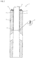
- Fig. 2 shows the lower end of the mast assembly 1 on an enlarged scale.
- the mast 3 is inserted into the foundation 2, acting as a reinforcement exhibiting, formed by centrifugal component is formed.
- the foundation 2 has a conical opening 4, which tapers downwards. In this cone-shaped opening 4 of the mast base is used. Because of the conicity of the mast 3, this has the largest diameter in the area of his foot. Conversely, the diameter of the opening 4 of the foundation 2 decreases downwards, so that a circular contact surface 5 between the mast 3 and the foundation 2 is formed.
- the foundation 2 has an enlarged cone angle in this area.
- annular clearance 7 is formed between the outside of the mast 3 and the inside 8 of the opening 4 of the foundation 2. Since the inner diameter of the foundation 2 at its upper end 6 is greater than the diameter of the mast 3 in this area, the mast 3 at this point does not touch the foundation 2 directly.
- Fig. 3 is a sectional view of another embodiment of a foundation 9, which has the basic shape of a truncated cone having at its top an opening into which the mast 3 can be used.
- the foundation 9 has a steel reinforcement 10,
- the slightly conical opening 4 is connected to two lateral channels 11, can be passed through the lines for power supply and for controlling the lighting.
- the 4 and 5 show the upper end of the foundation 2 in a sectional side view and a plan view.
- an annular flange plate 12 is attached, which is screwed by means of screws 13 with the foundation 2.
- the flange plate 12 consists of two semi-circular, screwed together sections 14, 15. By means of screw 16, the two sections 14, 15 of the flange plate 12 are interconnected.
- the two-part flange plate 12 allows their installation after insertion of the mast in the foundation.
- the inner diameter 17 of the flange plate 12 corresponds to the outer diameter of the mast 3 at this point, optionally, the inner diameter 17 may be slightly larger than the outer diameter of the mast 3, so that at this point a small gap is present.
- long slots can be provided on the foundation 2, which allow a certain displacement or adjustment of the flange 12.
- the mast 3 consists in this embodiment of thin steel sheet with a wall thickness of 2 mm, in principle, wall thicknesses between 1.5 mm and 2.5 mm come into question.
- the mast 3 is laser-welded, only with this manufacturing method, a high quality of the weld can be achieved in this thin-walled material.
- the conicity of the mast is 11 mm / m in this embodiment.
- the mast consists of glass fiber reinforced plastic (GRP).
- Fig. 6 shows a detail of the mast 3 in the area of a door cutout.
- the mast 3 has a substantially rectangular door opening 18 with rounded corners.
- reinforcements 19 are mounted on both sides of the inside.
- the reinforcements 19 are attached to the mast 3 by means of rivets 20.
- the reinforcements 19 In the horizontally cut view of Fig. 7 it can be seen that the reinforcements 19 have a substantially rectangular basic shape and form on both sides of the door cutout 18 abutment surfaces 21 for a door 22.
- Fig. 8 shows the mast 3 in the region of the flange plate 12 in a perspective view. There it can be seen that the top of the foundation 2 is installed substantially flush with the surface, the flange 12 protrudes from the surface. Between the mast 3 and the flange plate 12 no or only a small gap is formed. The two semicircular sections are positively and positively coupled.
- Fig. 9 shows the mast arrangement of Fig. 8 after carrying out a crash test.
- Such impact tests are defined in DIN EN 12767 in order to test the behavior of such masts in the event of an impact by a motor vehicle.
- a motor vehicle with a fixed speed and mass is allowed to collide with the mast.
- Fig. 9 shows the deformations of the in Fig. 8 shown mast assembly 1 after the crash test. It can be seen that the mast 3 has been largely flattened by the collision, in addition, the mast 3 is bent approximately at right angles in the region of the flange plate 12. In the edge region 23 of the mast 3 considerable plastic deformation of the thin-walled steel can be seen. It is essential, however, that the mast 3 is not torn off in the region of the flange plate 12.
Landscapes
- Engineering & Computer Science (AREA)
- Life Sciences & Earth Sciences (AREA)
- General Life Sciences & Earth Sciences (AREA)
- Mining & Mineral Resources (AREA)
- Paleontology (AREA)
- Civil Engineering (AREA)
- General Engineering & Computer Science (AREA)
- Structural Engineering (AREA)
- Foundations (AREA)
Abstract
Description
- Die Erfindung betrifft eine Mastanordnung, umfassend einen rohrförmigen, in ein Fundament eingesetzten Mast.
- Derartige Mastanordnungen werden überwiegend als Lichtmast entlang von Straßen eingesetzt und bestehen aus einem meist konusförmigen Mast, der in einem Fundament verankert ist. Am oberen Ende des Masts ist ein Beleuchtungselement angebracht, gegebenenfalls auch an einem Ausleger. Der in dieser Anmeldung verwendete Begriff Mastanordnung umfasst auch für andere Zwecke als zur Straßenbeleuchtung vorgesehene Masten, beispielsweise können diese auch Verkehrszeichen, Stromleitungen oder Antennen tragen.
- Die Anforderungen an Masten, die entlang von Straßen aufgestellt sind, sind in der Norm DIN EN 12767 "Passive Sicherheit von Tragkonstruktionen für die Straßenausstattung" festgelegt. Da der Grad der Gefährdung von Fahrzeuginsassen bei einem Anprall eines Fahrzeugs von dem Verhalten des Masts abhängig ist, versucht man Masten so zu konstruieren, dass sie sich beim Anprall des Fahrzeugs lösen oder nachgeben. Wenn sich ein Mast aus der Verankerung löst, wird er jedoch häufig weit weg geschleudert, wodurch die Gefahr von Sekundärkollisionen mit Bauwerken, Bäumen, Fußgängern oder anderen Verkehrsteilnehmern besteht. Um dieses unerwünschte Verhalten zu vermeiden, hat man in der Vergangenheit zumeist die Wandstärke des Masts erhöht, dies führt jedoch zu einer beträchtlichen Kostensteigerung.
- Der Erfindung liegt daher die Aufgabe zugrunde, eine Mastanordnung mit einem Mast anzugeben, der bei einer Kollision mit einem Fahrzeug nicht abreißt und dennoch eine hohe Energieabsorption besitzt.
- Zur Lösung dieser Aufgabe ist bei einer Mastanordnung der eingangs genannten Art erfindungsgemäß vorgesehen, dass der Innendurchmesser des Fundaments im Bereich seines oberen Endes größer als der Durchmesser des Masts in diesem Bereich ist.
- Bei der erfindungsgemäßen Mastanordnung ist der Durchmesser des Fundaments an dessen Oberkante größer als der Durchmesser des Masts, so dass ein Freiraum zwischen der Innenseite des Fundaments und der Außenseite des Masts gebildet ist. Bei einer Kollision kann sich der Mast in diesem Freiraum plastisch verformen, ohne dass er abreißt. Der ursprünglich kreisförmige Querschnitt des Masts wird bei der Kollision zusammengedrückt, wodurch ein beträchtlicher Teil der Aufprallenergie absorbiert wird. Dadurch werden einerseits Sekundärkollisionen vermieden, da der Mast nicht abreißt, zugleich wird die kinetische Energie des aufprallenden Fahrzeugs beträchtlich verringert, wodurch sich die Gefahr von Verletzungen der Fahrzeuginsassen verringert.
- Bei der erfindungsgemäßen Mastanordnung wird es bevorzugt, dass im Bereich des oberen Endes des Fundaments ein ringförmiger Freiraum zwischen der Außenseite des Masts und der Innenseite des Fundaments gebildet ist. Dadurch ergibt sich der Vorteil, dass der Mast bei einem Aufprall in alle Richtungen ausweichen kann, dementsprechend kann die Mastanordnung einem Aufprall aus einer beliebigen Richtung widerstehen.
- Um die Stabilität des Fundaments an dessen oberen Ende zu erhöhen, kann an der Oberseite des Fundaments eine ringförmige Flanschplatte angebracht sein. Bei einem Aufprall kommt der Mast mit der Flanschplatte in Kontakt, woraufhin der Mast plastisch verformt wird.
- Eine weitere Ausgestaltung der Erfindung kann vorsehen, dass die Flanschplatte aus zwei halbkreisförmigen, miteinander verschraubten und/oder form- und/oder kraftschlüssig miteinander verbundenen Abschnitten besteht. Bei dieser Variante kann die Flanschplatte bei oder nach der Montage des Masts leicht angebracht werden.
- Bei der erfindungsgemäßen Mastanordnung kann es vorgesehen sein, dass das Fundament konisch nach unten verjüngt ist, wobei der Konuswinkel und der Innendurchmesser des Fundaments vorzugsweise so gewählt sind, dass das untere Ende des Masts eine ringförmige Kontaktfläche mit der Innenseite des Fundaments bildet. Das untere Ende des Masts oder ein dazu benachbarter Bereich liegt somit linienförmig an der Innenseite des Fundaments an, wodurch sich eine ringförmige Kontaktfläche ergibt. Die Kontaktfläche kann sowohl linienförmig als auch flächig ausgebildet sein. Durch die zwischen der Innenseite des Fundaments und dem Mast auftretende Reibung wird dieser sicher gehalten.
- Es liegt auch im Rahmen der Erfindung, dass das Fundament ein eine Bewehrung aufweisendes, im Schleuderverfahren hergestelltes Bauteil ist oder alternativ aus Stahl besteht. Da das Fundament rotationssymmetrisch ausgebildet sein kann, bietet sich eine Herstellung im Schleuderverfahren an. Es sind jedoch auch andere Ausführungen denkbar, bei denen das Fundament als geschweißte Stahlkonstruktion ausgebildet sein kann.
- Im Hinblick auf den Mast wird es besonders bevorzugt, dass dieser aus Stahl besteht und mittels eines Lasers geschweißt ist. Der Mast weist und eine Wandstärke von 1,5 mm bis 2,5 mm, vorzugsweise 2 mm, auf. Nur durch ein Laserschweißverfahren lassen sich derart dünne Wandstärken mit hoher Qualität herstellen. Da der Mast lediglich die geringe Wandstärke von vorzugsweise 2 mm aufweist, kann er besonders Material sparend hergestellt werden.
- Alternativ kann der Mast aus glasfaserverstärktem Kunststoff (GFK) hergestellt sein.
- Im Rahmen einer Weiterbildung der Erfindung kann es vorgesehen sein, dass der Mast einen Türausschnitt mit innenseitigen senkrechten Verstärkungen aufweist, die mit dem Mast vernietet oder verschraubt oder verschweißt sind. Durch die Verstärkungen wird im Bereich des Türausschnitts eine ausreichende Stabilität erzielt, so dass ein Schutz vor Vandalismus gegeben ist.
- Weitere Vorteile und Einzelheiten der Erfindung werden nachfolgend anhand eines Ausführungsbeispiels unter Bezugnahme auf die Zeichnungen erläutert. Die Zeichnungen sind schematische Darstellungen und zeigen:
- Fig. 1
- eine geschnittene Seitenansicht eines ersten Ausführungsbeispiels einer erfindungsgemäßen Mastanordnung;
- Fig. 2
- eine geschnittene Seitenansicht der Mastanordnung von
Fig. 1 im Bereich des Fundaments; - Fig. 3
- ein weiteres Ausführungsbeispiel eines Fundaments in einer geschnittenen Seitenansicht;
- Fig. 4
- eine vergrößerte Ansicht des oberen Bereichs des Fundaments in einer geschnittenen Seitenansicht;
- Fig. 5
- eine Draufsicht des oberen Bereichs des Fundaments von
Fig. 4 ; - Fig. 6
- ein Detail der Mastanordnung im Bereich eines Türausschnitts;
- Fig. 7
- eine horizontal geschnittene Ansicht des Masts von
Fig. 6 ; - Fig. 8
- eine perspektivische Ansicht der Mastanordnung im Bereich der Oberkante des Fundaments; und
- Fig. 9
- die Mastanordnung von
Fig. 8 nach einem Crashversuch. - Die in
Fig. 1 gezeigte Mastanordnung 1 umfasst einen rohrförmigen, in ein Fundament 2 eingesetzten Mast 3. In dem dargestellten Ausführungsbeispiel ist der Mast 3 konusförmig ausgebildet, am oberen Ende des Masts 3, am sogenannten Zopf, beträgt dessen Durchmesser weniger als die Hälfte des Durchmessers am unteren Ende, dem Mastfuß. Der Mast 3 ist als Lichtmast ausgebildet und trägt an seinem oberen Ende ein (nicht dargestelltes) Beleuchtungselement. -
Fig. 2 zeigt das untere Ende der Mastanordnung 1 in einem vergrößerten Maßstab. Der Mast 3 ist in das Fundament 2 eingesetzt, das als eine Bewehrung aufweisendes, im Schleuderverfahren hergestelltes Bauteil ausgebildet ist. Das Fundament 2 weist eine konische Öffnung 4 auf, die sich nach unten verjüngt. In diese konusförmige Öffnung 4 ist der Mastfuß eingesetzt. Wegen der Konizität des Masts 3 weist dieser im Bereich seines Fußes den größten Durchmesser auf. Umgekehrt verringert sich der Durchmesser der Öffnung 4 des Fundaments 2 nach unten, so dass eine kreisförmige Berührfläche 5 zwischen dem Mast 3 und dem Fundament 2 gebildet ist. In der vergrößerten Ansicht im rechten Teil vonFig. 2 erkennt man, dass das Fundament 2 in diesem Bereich einen vergrößerten Konuswinkel aufweist. Am oberen Ende 6 des Fundaments 2 ist ein ringförmiger Freiraum 7 zwischen der Außenseite des Masts 3 und der Innenseite 8 der Öffnung 4 des Fundaments 2 gebildet. Da der Innendurchmesser des Fundaments 2 an seinem oberen Ende 6 größer als der Durchmesser des Masts 3 in diesem Bereich ist, berührt der Mast 3 an dieser Stelle das Fundament 2 nicht direkt. - Wesentlich ist, dass an der Oberseite des Fundaments 2 eine ringförmige, mit dem Fundament verschraubte Flanschplatte angebracht ist und dass im Bereich des oberen Endes 6 der ringförmige Freiraum 7 gebildet ist, der durch die ringförmige Flanschplatte, die Außenseite des Masts 3 und die Innenseite des Fundaments begrenzt wird. Die
Fig. 4 und 5 zeigen eine derartige Flanschplatte 12 im Detail. Die Flanschplatte dient dazu, den Mast seitlich zu stützen. Der konische Ringraum ermöglicht bei einem Aufprall eine plastische Verformung des Masts, ohne dass es zu hohen Spannungsspitzen im Bereich der Einspannstelle kommt, die bei herkömmlichen Mastanordnungen ein Abreißen des Masts zur Folge haben. Stattdessen wird bei einem Aufprall ein großer Teil der Aufprallenergie durch plastische Verformung des Masts absorbiert, der sich in dem konischen Freiraum bewegen kann. Die Folgen für Unfallbeteiligte sind weniger schwerwiegend, da ein Wegschleudern eines abgerissenen Mastabschnitts verhindert wird. -
Fig. 3 ist eine geschnittene Darstellung eines anderen Ausführungsbeispiels eines Fundaments 9, das die Grundform eines Kegelstumpfs besitzt, der an seiner Oberseite eine Öffnung aufweist, in die der Mast 3 eingesetzt werden kann. InFig. 3 erkennt man, dass das Fundament 9 eine Stahlbewehrung 10 aufweist, zusätzlich ist die leicht konische Öffnung 4 mit zwei seitlichen Kanälen 11 verbunden, durch die Leitungen zur Stromversorgung und zur Steuerung der Beleuchtung geführt werden können. - Die
Fig. 4 und 5 zeigen das obere Ende des Fundaments 2 in einer geschnittenen Seitenansicht und einer Draufsicht. Auf der ebenen Oberseite des Fundaments 2 ist eine ringförmige Flanschplatte 12 angebracht, die mittels Schrauben 13 mit dem Fundament 2 verschraubt ist. Die Flanschplatte 12 besteht aus zwei halbkreisförmigen, miteinander verschraubten Abschnitten 14, 15. Mittels Schraubverbindungen 16 sind die beiden Abschnitte 14, 15 der Flanschplatte 12 miteinander verbunden. Die zweiteilige Flanschplatte 12 erlaubt deren Montage nach dem Einsetzen des Masts in das Fundament. Es sind allerdings auch andere Ausführungen mit einer einteiligen Flanschplatte denkbar, die vor dem Einsetzen des Fundaments angebracht wird. - Der Innendurchmesser 17 der Flanschplatte 12 entspricht dem Außendurchmesser des Masts 3 an dieser Stelle, gegebenenfalls kann der Innendurchmesser 17 geringfügig größer als der Außendurchmesser des Masts 3 sein, so dass an dieser Stelle ein geringer Spalt vorhanden ist. Zur exakt senkrechten Ausrichtung des Masts 3 in dem Fundament 2 können an dem Fundament 2 Langlöcher vorgesehen sein, die eine gewisse Verschiebung bzw. Justierung der Flanschplatte 12 ermöglichen.
- Der Mast 3 besteht in diesem Ausführungsbeispiel aus dünnem Stahlblech mit einer Wandstärke von 2 mm, grundsätzlich kommen Wandstärken zwischen 1,5 mm und 2,5 mm in Frage. Der Mast 3 ist lasergeschweißt, nur mit diesem Herstellungsverfahren kann eine hohe Güte der Schweißnaht bei diesem dünnwandigen Material erzielt werden. Die Konizität des Masts beträgt in diesem Ausführungsbeispiel 11 mm/m. Es sind auch andere Ausführungen möglich, bei denen der Mast aus glasfaserverstärktem Kunststoff (GFK) besteht.
-
Fig. 6 zeigt ein Detail des Masts 3 im Bereich eines Türausschnitts. Um die Zugänglichkeit zu elektrischen Bauteilen für das am Mastzopf angeordnete Beleuchtungselement zu gewährleisten, weist der Mast 3 einen im Wesentlichen rechteckigen Türausschnitt 18 mit abgerundeten Ecken auf. Um den Mast 3 in diesem Bereich zu verstärken, sind an der Innenseite beidseitig Verstärkungen 19 angebracht. Die Verstärkungen 19 sind mittels Nieten 20 an dem Mast 3 angebracht. In der horizontal geschnittenen Ansicht vonFig. 7 erkennt man, dass die Verstärkungen 19 eine im Wesentlichen rechteckige Grundform aufweisen und an beiden Seiten des Türausschnitts 18 Anlageflächen 21 für eine Tür 22 bilden. -
Fig. 8 zeigt den Mast 3 im Bereich der Flanschplatte 12 in einer perspektivischen Ansicht. Dort erkennt man, dass die Oberseite des Fundaments 2 im Wesentlichen oberflächenbündig eingebaut ist, die Flanschplatte 12 steht von der Oberfläche hervor. Zwischen dem Mast 3 und der Flanschplatte 12 ist kein bzw. lediglich ein geringer Spalt gebildet. Die beiden halbkreisförmigen Abschnitte sind kraft- und formschlüssig gekoppelt. -
Fig. 9 zeigt die Mastanordnung vonFig. 8 nach der Durchführung eines Crashversuchs. Derartige Anprallversuche sind in der DIN EN 12767 definiert, um das Verhalten derartiger Masten bei einem Anprall durch ein Kraftfahrzeug zu testen. Man lässt dazu ein Kraftfahrzeug mit festgelegter Geschwindigkeit und Masse mit dem Mast kollidieren.Fig. 9 zeigt die aufgetretenen Verformungen der inFig. 8 gezeigten Mastanordnung 1 nach dem Crashversuch. Man erkennt, dass der Mast 3 durch die Kollision weitgehend flachgedrückt wurde, zudem ist der Mast 3 im Bereich der Flanschplatte 12 näherungsweise rechtwinklig abgeknickt. Im Randbereich 23 des Masts 3 sind beträchtliche plastische Verformungen des dünnwandigen Stahls zu erkennen. Wesentlich ist jedoch, dass der Mast 3 nicht im Bereich der Flanschplatte 12 abgerissen ist. Der Grund dafür ist der Freiraum 7, der unterhalb der Flanschplatte 12 zwischen der Außenseite des Masts 3 und der Innenseite 8 des Fundaments 2 gebildet ist. Dieser Freiraum 7 ermöglicht eine beträchtliche Verformung des Masts 3 im plastischen Bereich, ohne dass die Bruchlast des verwendeten Stahls erreicht wird. Dementsprechend kommt es nicht zu einem Abreißen des Masts 3, stattdessen wird dieser unter beträchtlicher Energieabsorption plastisch verformt. Bei einem Anprall durch ein Fahrzeug wird der Mast 3 praktisch auf seiner gesamten Länge nach und nach verformt. Dadurch ergibt sich der Vorteil, dass das den Aufprall verursachende Kraftfahrzeug kontinuierlich abgebremst wird, wodurch die Gefahr von Verletzungen der Fahrzeuginsassen vermindert wird. Zudem wird ein gefährliches Abreißen des Masts an der Einspannstelle vermieden, so dass Sekundärkollisionen verhindert werden.
Claims (9)
- Mastanordnung, umfassend einen rohrförmigen, in ein Fundament eingesetzten Mast, dadurch gekennzeichnet, dass der Innendurchmesser des Fundaments im Bereich seines oberen Endes größer als der Durchmesser des Masts in diesem Bereich ist.
- Mastanordnung nach Anspruch 1, dadurch gekennzeichnet, dass im Bereich des oberen Endes des Fundaments ein ringförmiger Freiraum zwischen der Außenseite des Masts und der Innenseite des Fundaments gebildet ist.
- Mastanordnung nach Anspruch 1 oder 2, dadurch gekennzeichnet, dass an der Oberseite des Fundaments eine ringförmige Flanschplatte angebracht ist.
- Mastanordnung nach Anspruch 3, dadurch gekennzeichnet, dass die Flanschplatte aus zwei halbkreisförmigen, miteinander verschraubten Abschnitten besteht.
- Mastanordnung nach einem der vorangehenden Ansprüche, dadurch gekennzeichnet, dass das Fundament konisch nach unten verjüngt ist, wobei der Konuswinkel und der Innendurchmesser des Fundaments vorzugsweise so gewählt sind, dass das untere Ende des Masts eine ringförmige Kontaktfläche mit der Innenseite des Fundaments bildet.
- Mastanordnung nach einem der vorangehenden Ansprüche, dadurch gekennzeichnet, dass das Fundament ein eine Bewehrung aufweisendes, im Schleuderverfahren hergestelltes Bauteil ist oder alternativ aus Stahl besteht.
- Mastanordnung nach einem der vorangehenden Ansprüche, dadurch gekennzeichnet, dass der Mast lasergeschweißt ist und eine Wandstärke von 1,5 mm bis 2,5 mm, vorzugsweise 2 mm, aufweist.
- Mastanordnung nach einem der Ansprüche 1 bis 6, dadurch gekennzeichnet, dass der Mast aus glasfaserverstärktem Kunststoff (GFK) besteht.
- Mastanordnung nach einem der vorangehenden Ansprüche, dadurch gekennzeichnet, dass der Mast einen Türausschnitt mit innenseitigen senkrechten Verstärkungen aufweist, die mit dem Mast vernietet oder verschraubt oder verschweißt sind.
Priority Applications (1)
| Application Number | Priority Date | Filing Date | Title |
|---|---|---|---|
| PL13187002T PL2716819T3 (pl) | 2012-10-02 | 2013-10-02 | Układ masztu |
Applications Claiming Priority (1)
| Application Number | Priority Date | Filing Date | Title |
|---|---|---|---|
| DE102012109357.1A DE102012109357A1 (de) | 2012-10-02 | 2012-10-02 | Mastanordnung |
Publications (2)
| Publication Number | Publication Date |
|---|---|
| EP2716819A1 true EP2716819A1 (de) | 2014-04-09 |
| EP2716819B1 EP2716819B1 (de) | 2018-03-28 |
Family
ID=49322203
Family Applications (1)
| Application Number | Title | Priority Date | Filing Date |
|---|---|---|---|
| EP13187002.4A Active EP2716819B1 (de) | 2012-10-02 | 2013-10-02 | Mastanordnung |
Country Status (6)
| Country | Link |
|---|---|
| EP (1) | EP2716819B1 (de) |
| DE (1) | DE102012109357A1 (de) |
| DK (1) | DK2716819T3 (de) |
| LT (1) | LT2716819T (de) |
| NO (1) | NO2852673T3 (de) |
| PL (1) | PL2716819T3 (de) |
Citations (4)
| Publication number | Priority date | Publication date | Assignee | Title |
|---|---|---|---|---|
| DE1913331A1 (de) * | 1969-03-15 | 1970-09-24 | Adolf Schuch Kg Lichttechn Spe | Leuchtenmast aus Kunststoff |
| AT403557B (de) * | 1995-10-13 | 1998-03-25 | Kern Harald Dipl Ing | Vorrichtung zum herstellen von rohren nach dem schleuderverfahren |
| EP2236238A1 (de) * | 2009-04-03 | 2010-10-06 | Europoles Sp. z.o.o. | Konischer Mast mit einer durch Laser geschweissten Längsnaht und Laser-Schweissverfahren zu seiner Herstellung |
| DE202010015031U1 (de) * | 2010-11-05 | 2011-03-10 | Brinkmann, Marlene | Schilderfundament |
-
2012
- 2012-10-02 DE DE102012109357.1A patent/DE102012109357A1/de not_active Withdrawn
-
2013
- 2013-05-23 NO NO13793326A patent/NO2852673T3/no unknown
- 2013-10-02 PL PL13187002T patent/PL2716819T3/pl unknown
- 2013-10-02 DK DK13187002.4T patent/DK2716819T3/en active
- 2013-10-02 LT LTEP13187002.4T patent/LT2716819T/lt unknown
- 2013-10-02 EP EP13187002.4A patent/EP2716819B1/de active Active
Patent Citations (4)
| Publication number | Priority date | Publication date | Assignee | Title |
|---|---|---|---|---|
| DE1913331A1 (de) * | 1969-03-15 | 1970-09-24 | Adolf Schuch Kg Lichttechn Spe | Leuchtenmast aus Kunststoff |
| AT403557B (de) * | 1995-10-13 | 1998-03-25 | Kern Harald Dipl Ing | Vorrichtung zum herstellen von rohren nach dem schleuderverfahren |
| EP2236238A1 (de) * | 2009-04-03 | 2010-10-06 | Europoles Sp. z.o.o. | Konischer Mast mit einer durch Laser geschweissten Längsnaht und Laser-Schweissverfahren zu seiner Herstellung |
| DE202010015031U1 (de) * | 2010-11-05 | 2011-03-10 | Brinkmann, Marlene | Schilderfundament |
Also Published As
| Publication number | Publication date |
|---|---|
| DE102012109357A1 (de) | 2014-04-03 |
| NO2852673T3 (de) | 2018-05-05 |
| LT2716819T (lt) | 2018-07-10 |
| EP2716819B1 (de) | 2018-03-28 |
| PL2716819T3 (pl) | 2018-09-28 |
| DK2716819T3 (en) | 2018-07-02 |
Similar Documents
| Publication | Publication Date | Title |
|---|---|---|
| DE69832599T2 (de) | Leitplankenpfosten mit sollbruchstelle für schienenende | |
| EP2455546B1 (de) | Pfostenanordnung für eine Schutzplankenkonstruktion und Schutzplankenkonstruktion zur Absicherung von Fahrbahnen auf Bauwerken | |
| EP1762660B1 (de) | Verkehrs-Leit-Einrichtung | |
| WO2018130553A1 (de) | Vorrichtung zur sicherung von personen gegen absturz | |
| EP0874940A1 (de) | Schutzplankenanordnung | |
| EP3468821B1 (de) | Strukturbauteil für ein kraftfahrzeug mit verstärkungselement | |
| AU2015389849B2 (en) | Spacer for road safety barrier | |
| EP1452666B1 (de) | Beton-Schutzwand | |
| EP3696322B1 (de) | Modulares verkehrszeichen | |
| EP1719840A2 (de) | Schutzplankenanordnung | |
| EP1061179A1 (de) | Schutzplankenanordnung | |
| EP2333159B1 (de) | Schutzplankenkonstruktion | |
| EP2716819B1 (de) | Mastanordnung | |
| EP2756990B1 (de) | Frontscheinwerfer | |
| DE102018212906B3 (de) | Karosseriestruktur für ein Fahrzeug | |
| DE102015004416A1 (de) | Frontpartie für ein Kraftfahrzeug | |
| DE102007063511B4 (de) | Schutzeinrichtung an Verkehrswegen | |
| EP2017387B1 (de) | Schutzplankenanordnung | |
| EP2904153B1 (de) | Rückhaltesystem und übergangskonstruktion zwischen zwei unterschiedliche seitliche steifigkeiten aufweisenden fahrzeugrückhaltesystemen | |
| EP3396067A1 (de) | Anbindungssystem zwischen einer anfangskonstruktion und einer schutzeinrichtung | |
| EP1460181B1 (de) | Anordnung mit einer Auffangvorrichtung gegen Ladungsabwurf von Fahrzeugen | |
| EP2681384B1 (de) | Sicherheitstragwerk | |
| DE202008011203U1 (de) | Fahrzeugrückhaltesystem an Verkehrswegen | |
| EP2246504B1 (de) | Konischer Mast | |
| EP1921211B1 (de) | Verkehrs-Leit-Einrichtung |
Legal Events
| Date | Code | Title | Description |
|---|---|---|---|
| PUAI | Public reference made under article 153(3) epc to a published international application that has entered the european phase |
Free format text: ORIGINAL CODE: 0009012 |
|
| AK | Designated contracting states |
Kind code of ref document: A1 Designated state(s): AL AT BE BG CH CY CZ DE DK EE ES FI FR GB GR HR HU IE IS IT LI LT LU LV MC MK MT NL NO PL PT RO RS SE SI SK SM TR |
|
| AX | Request for extension of the european patent |
Extension state: BA ME |
|
| 17P | Request for examination filed |
Effective date: 20140710 |
|
| RBV | Designated contracting states (corrected) |
Designated state(s): AL AT BE BG CH CY CZ DE DK EE ES FI FR GB GR HR HU IE IS IT LI LT LU LV MC MK MT NL NO PL PT RO RS SE SI SK SM TR |
|
| 17Q | First examination report despatched |
Effective date: 20160708 |
|
| GRAP | Despatch of communication of intention to grant a patent |
Free format text: ORIGINAL CODE: EPIDOSNIGR1 |
|
| INTG | Intention to grant announced |
Effective date: 20180103 |
|
| GRAS | Grant fee paid |
Free format text: ORIGINAL CODE: EPIDOSNIGR3 |
|
| GRAA | (expected) grant |
Free format text: ORIGINAL CODE: 0009210 |
|
| AK | Designated contracting states |
Kind code of ref document: B1 Designated state(s): AL AT BE BG CH CY CZ DE DK EE ES FI FR GB GR HR HU IE IS IT LI LT LU LV MC MK MT NL NO PL PT RO RS SE SI SK SM TR |
|
| REG | Reference to a national code |
Ref country code: GB Ref legal event code: FG4D Free format text: NOT ENGLISH |
|
| REG | Reference to a national code |
Ref country code: CH Ref legal event code: EP |
|
| REG | Reference to a national code |
Ref country code: AT Ref legal event code: REF Ref document number: 983567 Country of ref document: AT Kind code of ref document: T Effective date: 20180415 |
|
| REG | Reference to a national code |
Ref country code: IE Ref legal event code: FG4D Free format text: LANGUAGE OF EP DOCUMENT: GERMAN |
|
| REG | Reference to a national code |
Ref country code: DE Ref legal event code: R096 Ref document number: 502013009760 Country of ref document: DE |
|
| REG | Reference to a national code |
Ref country code: DK Ref legal event code: T3 Effective date: 20180629 |
|
| REG | Reference to a national code |
Ref country code: SE Ref legal event code: TRGR |
|
| REG | Reference to a national code |
Ref country code: NL Ref legal event code: FP |
|
| REG | Reference to a national code |
Ref country code: NO Ref legal event code: T2 Effective date: 20180328 |
|
| PG25 | Lapsed in a contracting state [announced via postgrant information from national office to epo] |
Ref country code: HR Free format text: LAPSE BECAUSE OF FAILURE TO SUBMIT A TRANSLATION OF THE DESCRIPTION OR TO PAY THE FEE WITHIN THE PRESCRIBED TIME-LIMIT Effective date: 20180328 |
|
| PG25 | Lapsed in a contracting state [announced via postgrant information from national office to epo] |
Ref country code: RS Free format text: LAPSE BECAUSE OF FAILURE TO SUBMIT A TRANSLATION OF THE DESCRIPTION OR TO PAY THE FEE WITHIN THE PRESCRIBED TIME-LIMIT Effective date: 20180328 Ref country code: GR Free format text: LAPSE BECAUSE OF FAILURE TO SUBMIT A TRANSLATION OF THE DESCRIPTION OR TO PAY THE FEE WITHIN THE PRESCRIBED TIME-LIMIT Effective date: 20180629 Ref country code: BG Free format text: LAPSE BECAUSE OF FAILURE TO SUBMIT A TRANSLATION OF THE DESCRIPTION OR TO PAY THE FEE WITHIN THE PRESCRIBED TIME-LIMIT Effective date: 20180628 |
|
| PG25 | Lapsed in a contracting state [announced via postgrant information from national office to epo] |
Ref country code: MT Free format text: LAPSE BECAUSE OF FAILURE TO SUBMIT A TRANSLATION OF THE DESCRIPTION OR TO PAY THE FEE WITHIN THE PRESCRIBED TIME-LIMIT Effective date: 20180328 |
|
| PG25 | Lapsed in a contracting state [announced via postgrant information from national office to epo] |
Ref country code: EE Free format text: LAPSE BECAUSE OF FAILURE TO SUBMIT A TRANSLATION OF THE DESCRIPTION OR TO PAY THE FEE WITHIN THE PRESCRIBED TIME-LIMIT Effective date: 20180328 Ref country code: IT Free format text: LAPSE BECAUSE OF FAILURE TO SUBMIT A TRANSLATION OF THE DESCRIPTION OR TO PAY THE FEE WITHIN THE PRESCRIBED TIME-LIMIT Effective date: 20180328 Ref country code: RO Free format text: LAPSE BECAUSE OF FAILURE TO SUBMIT A TRANSLATION OF THE DESCRIPTION OR TO PAY THE FEE WITHIN THE PRESCRIBED TIME-LIMIT Effective date: 20180328 Ref country code: ES Free format text: LAPSE BECAUSE OF FAILURE TO SUBMIT A TRANSLATION OF THE DESCRIPTION OR TO PAY THE FEE WITHIN THE PRESCRIBED TIME-LIMIT Effective date: 20180328 Ref country code: AL Free format text: LAPSE BECAUSE OF FAILURE TO SUBMIT A TRANSLATION OF THE DESCRIPTION OR TO PAY THE FEE WITHIN THE PRESCRIBED TIME-LIMIT Effective date: 20180328 |
|
| PG25 | Lapsed in a contracting state [announced via postgrant information from national office to epo] |
Ref country code: SK Free format text: LAPSE BECAUSE OF FAILURE TO SUBMIT A TRANSLATION OF THE DESCRIPTION OR TO PAY THE FEE WITHIN THE PRESCRIBED TIME-LIMIT Effective date: 20180328 Ref country code: CZ Free format text: LAPSE BECAUSE OF FAILURE TO SUBMIT A TRANSLATION OF THE DESCRIPTION OR TO PAY THE FEE WITHIN THE PRESCRIBED TIME-LIMIT Effective date: 20180328 Ref country code: SM Free format text: LAPSE BECAUSE OF FAILURE TO SUBMIT A TRANSLATION OF THE DESCRIPTION OR TO PAY THE FEE WITHIN THE PRESCRIBED TIME-LIMIT Effective date: 20180328 |
|
| PG25 | Lapsed in a contracting state [announced via postgrant information from national office to epo] |
Ref country code: PT Free format text: LAPSE BECAUSE OF FAILURE TO SUBMIT A TRANSLATION OF THE DESCRIPTION OR TO PAY THE FEE WITHIN THE PRESCRIBED TIME-LIMIT Effective date: 20180730 |
|
| REG | Reference to a national code |
Ref country code: DE Ref legal event code: R097 Ref document number: 502013009760 Country of ref document: DE |
|
| PLBE | No opposition filed within time limit |
Free format text: ORIGINAL CODE: 0009261 |
|
| STAA | Information on the status of an ep patent application or granted ep patent |
Free format text: STATUS: NO OPPOSITION FILED WITHIN TIME LIMIT |
|
| 26N | No opposition filed |
Effective date: 20190103 |
|
| PG25 | Lapsed in a contracting state [announced via postgrant information from national office to epo] |
Ref country code: SI Free format text: LAPSE BECAUSE OF FAILURE TO SUBMIT A TRANSLATION OF THE DESCRIPTION OR TO PAY THE FEE WITHIN THE PRESCRIBED TIME-LIMIT Effective date: 20180328 |
|
| REG | Reference to a national code |
Ref country code: CH Ref legal event code: PL |
|
| GBPC | Gb: european patent ceased through non-payment of renewal fee |
Effective date: 20181002 |
|
| PG25 | Lapsed in a contracting state [announced via postgrant information from national office to epo] |
Ref country code: MC Free format text: LAPSE BECAUSE OF FAILURE TO SUBMIT A TRANSLATION OF THE DESCRIPTION OR TO PAY THE FEE WITHIN THE PRESCRIBED TIME-LIMIT Effective date: 20180328 |
|
| REG | Reference to a national code |
Ref country code: IE Ref legal event code: MM4A |
|
| PG25 | Lapsed in a contracting state [announced via postgrant information from national office to epo] |
Ref country code: LI Free format text: LAPSE BECAUSE OF NON-PAYMENT OF DUE FEES Effective date: 20181031 Ref country code: CH Free format text: LAPSE BECAUSE OF NON-PAYMENT OF DUE FEES Effective date: 20181031 Ref country code: FR Free format text: LAPSE BECAUSE OF NON-PAYMENT OF DUE FEES Effective date: 20181031 |
|
| PG25 | Lapsed in a contracting state [announced via postgrant information from national office to epo] |
Ref country code: GB Free format text: LAPSE BECAUSE OF NON-PAYMENT OF DUE FEES Effective date: 20181002 Ref country code: IE Free format text: LAPSE BECAUSE OF NON-PAYMENT OF DUE FEES Effective date: 20181002 |
|
| REG | Reference to a national code |
Ref country code: AT Ref legal event code: MM01 Ref document number: 983567 Country of ref document: AT Kind code of ref document: T Effective date: 20181002 |
|
| PG25 | Lapsed in a contracting state [announced via postgrant information from national office to epo] |
Ref country code: AT Free format text: LAPSE BECAUSE OF NON-PAYMENT OF DUE FEES Effective date: 20181002 |
|
| PG25 | Lapsed in a contracting state [announced via postgrant information from national office to epo] |
Ref country code: TR Free format text: LAPSE BECAUSE OF FAILURE TO SUBMIT A TRANSLATION OF THE DESCRIPTION OR TO PAY THE FEE WITHIN THE PRESCRIBED TIME-LIMIT Effective date: 20180328 |
|
| PG25 | Lapsed in a contracting state [announced via postgrant information from national office to epo] |
Ref country code: HU Free format text: LAPSE BECAUSE OF FAILURE TO SUBMIT A TRANSLATION OF THE DESCRIPTION OR TO PAY THE FEE WITHIN THE PRESCRIBED TIME-LIMIT; INVALID AB INITIO Effective date: 20131002 Ref country code: MK Free format text: LAPSE BECAUSE OF NON-PAYMENT OF DUE FEES Effective date: 20180328 Ref country code: CY Free format text: LAPSE BECAUSE OF FAILURE TO SUBMIT A TRANSLATION OF THE DESCRIPTION OR TO PAY THE FEE WITHIN THE PRESCRIBED TIME-LIMIT Effective date: 20180328 |
|
| PG25 | Lapsed in a contracting state [announced via postgrant information from national office to epo] |
Ref country code: IS Free format text: LAPSE BECAUSE OF FAILURE TO SUBMIT A TRANSLATION OF THE DESCRIPTION OR TO PAY THE FEE WITHIN THE PRESCRIBED TIME-LIMIT Effective date: 20180728 |
|
| REG | Reference to a national code |
Ref country code: DE Ref legal event code: R082 Ref document number: 502013009760 Country of ref document: DE Representative=s name: DR. GASSNER & PARTNER MBB PATENTANWAELTE, DE Ref country code: DE Ref legal event code: R081 Ref document number: 502013009760 Country of ref document: DE Owner name: TECPOLES GMBH, DE Free format text: FORMER OWNER: EUROPOLES GMBH & CO. KG, 92318 NEUMARKT, DE |
|
| REG | Reference to a national code |
Ref country code: FI Ref legal event code: PCE Owner name: TECPOLES GMBH |
|
| REG | Reference to a national code |
Ref country code: NO Ref legal event code: CHAD Owner name: TECPOLES GMBH, DE |
|
| REG | Reference to a national code |
Ref country code: LU Ref legal event code: PD Owner name: TECPOLES GMBH; DE Free format text: FORMER OWNER: EUROPOLES GMBH & CO. KG Effective date: 20210707 |
|
| REG | Reference to a national code |
Ref country code: NL Ref legal event code: PD Owner name: TECPOLES GMBH; DE Free format text: DETAILS ASSIGNMENT: CHANGE OF OWNER(S), ASSIGNMENT; FORMER OWNER NAME: EUROPOLES GMBH & CO. KG Effective date: 20210713 |
|
| REG | Reference to a national code |
Ref country code: BE Ref legal event code: PD Owner name: TECPOLES GMBH; DE Free format text: DETAILS ASSIGNMENT: CHANGE OF OWNER(S), ASSIGNMENT; FORMER OWNER NAME: EUROPOLES GMBH & CO. KG Effective date: 20210709 |
|
| PGFP | Annual fee paid to national office [announced via postgrant information from national office to epo] |
Ref country code: LT Payment date: 20250919 Year of fee payment: 13 |
|
| PGFP | Annual fee paid to national office [announced via postgrant information from national office to epo] |
Ref country code: PL Payment date: 20250922 Year of fee payment: 13 |
|
| PGFP | Annual fee paid to national office [announced via postgrant information from national office to epo] |
Ref country code: NL Payment date: 20251023 Year of fee payment: 13 Ref country code: LU Payment date: 20251022 Year of fee payment: 13 |
|
| PGFP | Annual fee paid to national office [announced via postgrant information from national office to epo] |
Ref country code: DE Payment date: 20250811 Year of fee payment: 13 |
|
| PGFP | Annual fee paid to national office [announced via postgrant information from national office to epo] |
Ref country code: NO Payment date: 20251022 Year of fee payment: 13 |
|
| PGFP | Annual fee paid to national office [announced via postgrant information from national office to epo] |
Ref country code: FI Payment date: 20251022 Year of fee payment: 13 Ref country code: DK Payment date: 20251023 Year of fee payment: 13 |
|
| PGFP | Annual fee paid to national office [announced via postgrant information from national office to epo] |
Ref country code: BE Payment date: 20251022 Year of fee payment: 13 |
|
| PGFP | Annual fee paid to national office [announced via postgrant information from national office to epo] |
Ref country code: SE Payment date: 20251023 Year of fee payment: 13 |
|
| PGFP | Annual fee paid to national office [announced via postgrant information from national office to epo] |
Ref country code: LV Payment date: 20251021 Year of fee payment: 13 |