EP2716319A1 - Larynxmaske - Google Patents
Larynxmaske Download PDFInfo
- Publication number
- EP2716319A1 EP2716319A1 EP12793620.1A EP12793620A EP2716319A1 EP 2716319 A1 EP2716319 A1 EP 2716319A1 EP 12793620 A EP12793620 A EP 12793620A EP 2716319 A1 EP2716319 A1 EP 2716319A1
- Authority
- EP
- European Patent Office
- Prior art keywords
- ring
- hyoid bone
- laryngeal mask
- cuff
- shaped cuff
- Prior art date
- Legal status (The legal status is an assumption and is not a legal conclusion. Google has not performed a legal analysis and makes no representation as to the accuracy of the status listed.)
- Granted
Links
Images





Classifications
-
- A—HUMAN NECESSITIES
- A61—MEDICAL OR VETERINARY SCIENCE; HYGIENE
- A61M—DEVICES FOR INTRODUCING MEDIA INTO, OR ONTO, THE BODY; DEVICES FOR TRANSDUCING BODY MEDIA OR FOR TAKING MEDIA FROM THE BODY; DEVICES FOR PRODUCING OR ENDING SLEEP OR STUPOR
- A61M16/00—Devices for influencing the respiratory system of patients by gas treatment, e.g. ventilators; Tracheal tubes
- A61M16/04—Tracheal tubes
- A61M16/0434—Cuffs
-
- A—HUMAN NECESSITIES
- A61—MEDICAL OR VETERINARY SCIENCE; HYGIENE
- A61F—FILTERS IMPLANTABLE INTO BLOOD VESSELS; PROSTHESES; DEVICES PROVIDING PATENCY TO, OR PREVENTING COLLAPSING OF, TUBULAR STRUCTURES OF THE BODY, e.g. STENTS; ORTHOPAEDIC, NURSING OR CONTRACEPTIVE DEVICES; FOMENTATION; TREATMENT OR PROTECTION OF EYES OR EARS; BANDAGES, DRESSINGS OR ABSORBENT PADS; FIRST-AID KITS
- A61F7/00—Heating or cooling appliances for medical or therapeutic treatment of the human body
- A61F7/12—Devices for heating or cooling internal body cavities
- A61F7/123—Devices for heating or cooling internal body cavities using a flexible balloon containing the thermal element
-
- A—HUMAN NECESSITIES
- A61—MEDICAL OR VETERINARY SCIENCE; HYGIENE
- A61M—DEVICES FOR INTRODUCING MEDIA INTO, OR ONTO, THE BODY; DEVICES FOR TRANSDUCING BODY MEDIA OR FOR TAKING MEDIA FROM THE BODY; DEVICES FOR PRODUCING OR ENDING SLEEP OR STUPOR
- A61M16/00—Devices for influencing the respiratory system of patients by gas treatment, e.g. ventilators; Tracheal tubes
- A61M16/04—Tracheal tubes
- A61M16/0402—Special features for tracheal tubes not otherwise provided for
- A61M16/0409—Special features for tracheal tubes not otherwise provided for with mean for closing the oesophagus
-
- A—HUMAN NECESSITIES
- A61—MEDICAL OR VETERINARY SCIENCE; HYGIENE
- A61M—DEVICES FOR INTRODUCING MEDIA INTO, OR ONTO, THE BODY; DEVICES FOR TRANSDUCING BODY MEDIA OR FOR TAKING MEDIA FROM THE BODY; DEVICES FOR PRODUCING OR ENDING SLEEP OR STUPOR
- A61M16/00—Devices for influencing the respiratory system of patients by gas treatment, e.g. ventilators; Tracheal tubes
- A61M16/04—Tracheal tubes
- A61M16/0402—Special features for tracheal tubes not otherwise provided for
- A61M16/0415—Special features for tracheal tubes not otherwise provided for with access means to the stomach
-
- A—HUMAN NECESSITIES
- A61—MEDICAL OR VETERINARY SCIENCE; HYGIENE
- A61M—DEVICES FOR INTRODUCING MEDIA INTO, OR ONTO, THE BODY; DEVICES FOR TRANSDUCING BODY MEDIA OR FOR TAKING MEDIA FROM THE BODY; DEVICES FOR PRODUCING OR ENDING SLEEP OR STUPOR
- A61M16/00—Devices for influencing the respiratory system of patients by gas treatment, e.g. ventilators; Tracheal tubes
- A61M16/04—Tracheal tubes
- A61M16/0434—Cuffs
- A61M16/0436—Special fillings therefor
- A61M16/0438—Liquid-filled
-
- A—HUMAN NECESSITIES
- A61—MEDICAL OR VETERINARY SCIENCE; HYGIENE
- A61M—DEVICES FOR INTRODUCING MEDIA INTO, OR ONTO, THE BODY; DEVICES FOR TRANSDUCING BODY MEDIA OR FOR TAKING MEDIA FROM THE BODY; DEVICES FOR PRODUCING OR ENDING SLEEP OR STUPOR
- A61M16/00—Devices for influencing the respiratory system of patients by gas treatment, e.g. ventilators; Tracheal tubes
- A61M16/04—Tracheal tubes
- A61M16/0434—Cuffs
- A61M16/0445—Special cuff forms, e.g. undulated
-
- A—HUMAN NECESSITIES
- A61—MEDICAL OR VETERINARY SCIENCE; HYGIENE
- A61M—DEVICES FOR INTRODUCING MEDIA INTO, OR ONTO, THE BODY; DEVICES FOR TRANSDUCING BODY MEDIA OR FOR TAKING MEDIA FROM THE BODY; DEVICES FOR PRODUCING OR ENDING SLEEP OR STUPOR
- A61M16/00—Devices for influencing the respiratory system of patients by gas treatment, e.g. ventilators; Tracheal tubes
- A61M16/04—Tracheal tubes
- A61M16/0488—Mouthpieces; Means for guiding, securing or introducing the tubes
-
- A—HUMAN NECESSITIES
- A61—MEDICAL OR VETERINARY SCIENCE; HYGIENE
- A61M—DEVICES FOR INTRODUCING MEDIA INTO, OR ONTO, THE BODY; DEVICES FOR TRANSDUCING BODY MEDIA OR FOR TAKING MEDIA FROM THE BODY; DEVICES FOR PRODUCING OR ENDING SLEEP OR STUPOR
- A61M2205/00—General characteristics of the apparatus
- A61M2205/36—General characteristics of the apparatus related to heating or cooling
- A61M2205/3606—General characteristics of the apparatus related to heating or cooling cooled
-
- A—HUMAN NECESSITIES
- A61—MEDICAL OR VETERINARY SCIENCE; HYGIENE
- A61M—DEVICES FOR INTRODUCING MEDIA INTO, OR ONTO, THE BODY; DEVICES FOR TRANSDUCING BODY MEDIA OR FOR TAKING MEDIA FROM THE BODY; DEVICES FOR PRODUCING OR ENDING SLEEP OR STUPOR
- A61M2210/00—Anatomical parts of the body
- A61M2210/10—Trunk
- A61M2210/1025—Respiratory system
- A61M2210/1028—Larynx
Definitions
- the present invention relates to a laryngeal mask.
- Laryngeal masks for securing an airway in the human body while blocking communication between the esophagus and the trachea are known in the prior art. An explanation is first provided of the structure of the human body J with reference to FIG. 6 .
- the human body J has a nasal cavity J1, an oral cavity J2, a pharyngeal portion T communicated with the nasal cavity J1 and the oral cavity J2, and an esophagus J5 and a trachea J6 branching from this pharyngeal portion T.
- a first constricting portion J4 which is constricted by the action of a sphincter for establishing or blocking communication between the esophagus J5 and the pharyngeal portion T, is formed on the upstream side of the esophagus J5.
- a laryngeal mask described in Patent Document 1 is provided with an airway tube inserted into the body through the oral cavity J2, and a masking ring provided on the leading end of this airway tube.
- the masking ring has an elliptical shape and can be inflated and deflated.
- the leading end of the airway tube opens into an interior region of the masking ring, and an artificial respirator can be connected to the base end of the airway tube.
- the airway tube is inserted into the body until the leading end of the deflated masking ring contacts the region of the sphincter (namely, the first constricting portion J4).
- a medical professional discontinues insertion of the laryngeal mask when a sensation is felt of the leading end of the masking ring having contacted the region of the sphincter.
- the masking ring adheres tightly to the opening of the trachea J6 as a result of being inflated.
- communication between the esophagus J5 and the trachea J6 is blocked.
- the trachea J6 is able to communicate with an artificial respirator through the airway tube that opens into the interior region of the masking ring.
- an airway can be secured while blocking communication between the esophagus J5 and the trachea J6.
- the depth at which the laryngeal mask described in Patent Document 1 is inserted into the body is determined based on the presence or absence of the sensation felt when the leading end of the masking ring contacts the region of the sphincter (namely, the first constricting portion J4).
- the region of the sphincter (the first constricting portion J4) is soft tissue and easily deformed. Consequently, it is difficult to accurately determine whether the masking ring has contacted the first constricting portion J4.
- the insertion site of the masking ring shifts from the target opening of the trachea J6, an airway cannot be accurately secured even if this masking ring is inflated.
- Patent Document 1 Japanese Unexamined Patent Publication No. 2003-511108 (and particularly, paragraph [0066])
- An object of the present invention is to provide a laryngeal mask that allows an airway to be accurately secured by a simple procedure.
- the present invention provides a laryngeal mask for securing an airway of a patient, provided with: an insertion tube, having a base end in which is formed a connecting portion capable of being connected to an artificial respirator, a leading end in which is formed a ventilation opening, and a communication passage formed therein that communicates between the connecting portion and the ventilation opening, a ring-shaped cuff which is attached to the leading end of the insertion tube so as to surround the ventilation opening, and is capable of tightly adhering to a tracheal opening of a patient trachea as a result of inflating in a state where the ring-shaped cuff is inserted to a predetermined insertion position in the patient, and at least one hyoid bone-contacting portion that protrudes laterally from the insertion tube so as to contact a site, in a pharyngeal portion of the patient, corresponding to a hyoid bone of the patient in a state where the
- an airway can be accurately secured by a simple procedure.
- the human body J has a nasal cavity J1, an oral cavity J2, a pharyngeal portion T communicated with the nasal cavity J1 and the oral cavity J2, an esophagus J5 and a trachea J6 branching from this pharyngeal portion T, an epiglottis J3 provided in the pharyngeal portion T for inhibiting entry of food into the trachea J6, and a U-shaped hyoid bone J7 surrounding the pharyngeal portion T from the anterior side and both the left and right sides in the vicinity of this epiglottis J3.
- a first constricting portion J4 which is constricted by the action of a sphincter for establishing or blocking communication between the esophagus J5 and the pharyngeal portion T, is formed on the upstream side of the esophagus J5.
- the pharyngeal portion T has an upper pharyngeal portion T1, which is provided in the range of the pharyngeal portion T above the branch of the nasal cavity J1 and the oral cavity J2, a middle pharyngeal portion T2, which is provided in the range of the pharyngeal portion T extending from the upper pharyngeal portion T1 to the epiglottis J3, and a lower pharyngeal portion T3, which is provided in the range of the pharyngeal portion T below this middle pharyngeal portion T2.
- the laryngeal mask 1 is for securing an airway as indicated by arrows Y1 in a state where the esophagus J5 and the trachea J6 blocked by a ring-shaped cuff 7.
- the laryngeal mask 1 is provided with a mask body 2 for securing an airway in the human body J, and a cooling portion 3 for cooling the pharyngeal portion T of the human body.
- the mask body 2 is provided with an insertion tube body 4 inserted into the body through the oral cavity J2 of the human body J, a connector 5 attached to the base end of the insertion tube body 4, a positioning member 6 for positioning the insertion depth of the insertion tube body 4 at a predetermined insertion position (see Fig. 7 ), and the ring-shaped cuff 7 attached to the leading end of the insertion tube body 4.
- the insertion tube body 4 is provided with an outer tube 4a for securing an airway in the human body J, and an inner tube 4b inserted inside the outer tube 4a.
- the outer tube 4a is curved corresponding to the route from the oral cavity J2 to the esophagus J5 of the human body J.
- the leading end of the outer tube 4a is in the form of an inclined plane facing the inside of the curved shape (side in which the center of the curve is positioned) of the outer tube 4a.
- a through hole is formed in the outer tube 4a and extends over the entire length in the lengthwise direction from the base end of the outer tube 4a to the leading end of the outer tube 4a.
- the through hole communicates from the opening of the leading end to the opening of the base end of the outer tube 4a.
- the inner tube 4b is for aspirating obstructive substances present in the esophagus J5 of the human body J. More specifically, the inner tube 4b extends beyond the leading end of the outer tube 4a and penetrates the ring-shaped cuff 7 to be subsequently described.
- the connector 5 is a Y-shaped tube for connecting an artificial respirator or aspirator and the like not shown to the insertion tube 4. More specifically, the connector 5 is provided with a cylindrical body portion 5a installed on the base end of the outer tube 4a, and cylindrical first connecting portion 5b and second connecting portion 5c that protrude from this body portion 5a and communicate within the body portion 5a.
- the base end of the outer tube 4a is fit into the body portion 5a in an airtight state.
- the base end of the inner tube 4b introduced into the connector 5 through the body portion 5a is fit into the second connecting portion 5c in an airtight state.
- the first connecting portion 5b communicates with the space outside the inner tube 4b in a space within the through hole of the outer tube 4a.
- the outer tube 4a and the connector 5 comprise an insertion tube that has a base end, in which is formed the first connecting portion 5b capable of connecting to an artificial respirator, and a leading end in which is formed a ventilation opening, and has a through hole formed therein that communicates between the first connecting portion 5b and the ventilation opening.
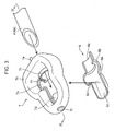
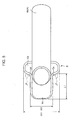
- the positioning member 6 is able to contact from above a site, within the pharyngeal portion T of the human body J, corresponding to the hyoid bone J7 as shown in Fig. 7 in a state where the ring-shaped cuff 7 to be subsequently described is inserted to the insertion position shown in Fig. 9 . More specifically, as shown in Figs. 3 to 5 , the positioning member 6 is provided with a tube connecting portion 6a connected to the outer tube 4a, a wide portion 6b provided on the leading end side of this tube connecting portion 6a, and an extending portion 6c extending from this wide portion 6b to the leading end side.
- the tube connecting portion 6a is formed into the shape of an arc having a radius of curvature that enables it to be arranged along the outer surface of the outer tube 4a. This tube connecting portion 6a is adhered to the outer surface of the outer tube 4a.
- the wide portion 6b has a width W1 larger than the diameter of the outer tube 4a (see Fig. 5 ). Both the left and right portions of this wide portion 6b protrude equally to the left and right from the outer tube 4a in a planer view.
- the extending portion 6c has a width W2 smaller than the wide portion 6b.
- the extending portion 6c protrudes to the leading end side from the center position in a right-and-left direction of the wide portion 6b so that hyoid bone-contacting portions 6d and 6e respectively remain on the left and right sides of the wide portion 6b.
- the portions of the wide portion 6b that protrude in the direction of width (right-and-left direction) from the extending portion 6c configure the two left and right hyoid bone-contacting portions 6d and 6e having equal widths.
- hyoid bone-contacting portions 6d and 6e are provided at positions able to contact a site corresponding to the hyoid bone J7 from above in a state where the ring-shaped cuff 7 to be subsequently described is inserted to a predetermined insertion position. More specifically, in the present embodiment, the hyoid bone-contacting portions 6d and 6e are respectively provided at the same positions in the lengthwise direction of the outer tube 4a. In addition, each of the hyoid bone-contacting portions 6d and 6e is provided at an interval that enables contact with portions on the left and right sides of a site corresponding to the hyoid bone J7 from above (this interval is about 40 mm in the present embodiment).
- the extending portion 6c is formed in the shape of a flat plate having a length L1 from the wide portion 6b. More specifically, the extending portion 6c extends to the leading end side beyond the leading end of the outer tube 4a. Consequently, the extending portion 6c can be slid into the narrow space between the epiglottis J3 and the posterior wall of the pharyngeal portion T even if the epiglottis J3 has descended as indicated by the double-dot broken line of Fig. 8 .
- the positioning member 6 has hardness that is at least harder than the ring-shaped cuff 7. More specifically, the hardness of the positioning member 6 can be adjusted according to the material and dimensions thereof.
- the ring-shaped cuff 7 can be tightly adhered to the tracheal opening of the trachea J6 by being inflated in a state where the ring-shaped cuff 7 is inserted to a predetermined insertion position as shown in Fig. 9 . More specifically, as shown in Figs.
- the ring-shaped cuff 7 is provided with a bottom portion 7a in the shape of a flat plate corresponding to the positioning member 6 (wide portion 6b and extending portion 6c), a ring-shaped cuff body 7b provided over the entire periphery of the peripheral edge of this bottom 7a, an outer tube attaching portion 7c for attaching the outer tube 4a, inner tube attaching portions 7d and 7f for attaching the inner tube 4b, and a gas supply and evacuation portion 7e for supplying and evacuating a gas to and from the ring-shaped cuff body 7b.
- a through hole 7g and a through hole 7h are formed in the bottom portion 7a.
- the outer tube 4a passes through the through hole 7h, and the opening in the leading end of the outer tube 4a is arranged substantially in the center of the ring-shaped cuff body 7b.
- the outer tube attaching portion 7c extends towards the leading end side from the lower portion of the base end side of the ring-shaped cuff body 7b and is adhered to the outer surface of the outer tube 4a.
- the inner tube 4b leading out from the outer tube 4a is adhered in an airtight state to the inner tube attaching portions 7d and 7f while passing through the leading end of the ring-shaped cuff body 7b.
- the inner tube attaching portions 7d and 7f respectively communicate with the inside of the ring-shaped cuff body 7b and are formed into the shape of a tube that enables the inner tube 4b to be inserted therein.
- the ring-shaped cuff body 7b is attached to the leading end of the outer tube 4a so as to surround the opening in the leading end of the outer tube 4a.
- the ring-shaped cuff body 7b can be inflated or deflated by supplying or evacuating a gas through the gas supply and evacuation portion 7e.
- An extension tube not shown and a supply and evacuation port not shown provided on the leading end of this extension tube are connected to the gas supply and evacuation portion 7e.
- the supply and evacuation port is led outside the human body J by the extension tube.
- the ring-shaped cuff body 7b is inflated or deflated by supplying or evacuating a gas to or from the ring-shaped cuff body 7b from outside the human body J through the gas supply and evaluation port.
- a surface on one side of the ring-shaped cuff body 7b (top surface in Fig. 4 ) is able to tightly adhere to the tracheal opening of the trachea J6 over the entire periphery thereof.
- the ring-shaped cuff 7, the positioning member 6 and the outer tube 4a are fixed in an airtight state to allow the outer tube 4a and the trachea J6 to reliably communicate while in this tightly adhered state. More specifically, the tube connecting portion 6a of the positioning member 6 is adhered in an airtight state to the outer tube 4a positioned farther towards the base end side than the through hole 7h of the bottom portion 7a.
- the extending portion 6c of the positioning member 6 is introduced to the inside of the ring-shaped cuff body 7b through the through hole 7g, and is adhered in an airtight state to the outer surface of the inner tube attaching portion 7d.
- Those portions of the positioning member 6 other than the tube connecting portion 6a and the extending portion 6c are adhered in an airtight state to the ring-shaped cuff 7 and/or the outer tube 4a.
- the ring-shaped cuff 7 is adhered in an airtight state to the outer tube 4a.
- the extending portion 6c of the positioning member 6 is adhered to the inner tube attaching portion 7d and not the ring-shaped cuff body 7b.
- the reason for this is to allow the ring-shaped cuff body 7b to be reliably adhered to the lower pharyngeal portion T3 by avoiding interposition by the positioning member 6 between the posterior surface of the ring-shaped cuff body 7b and the lower pharyngeal portion T3 (first constricting portion).
- the esophagus J5 and the trachea J6 are able to be reliably blocked by the ring-shaped cuff body 7b.
- the cooling portion 3 is able to cool the pharyngeal portion T by tightly adhering to the pharyngeal portion T in a state where the ring-shaped cuff 7 is inflated. More specifically, the cooling portion 3 is provided with a cooling cuff 8, which inflates as a result of housing a coolant and deflates as a result of evacuating the coolant, and a pair of supply and evacuation tubes 9 and 10 capable of supplying and evacuating the coolant to and from this cooling cuff 8.
- the cooling cuff 8 is able to inflate so as to tightly adhere to the posterior walls of the lower pharyngeal portion T3 and middle pharyngeal portion T2 (see Fig. 6 ) of the human body J in a state where the ring-shaped cuff 7 is inflated. More specifically, the cooling cuff 8 is provided with a fixing portion 11 in which the ring-shaped cuff 7 is fixed, and a pair of left and right extending portions 14 and 15 extending towards the base end side from this fixing portion 11. A accommodating chamber capable of accommodating a coolant is formed within the fixing portion 11. The insides of the pair of left and right extending portions 14 and 15 communicate with the accommodating chamber of the fixing portion 11, and accommodating chambers capable of housing a coolant are respectively formed in the insides of the pair of left and right extending portions 14 and 15.
- the fixing portion 11 is provided on the opposite side from the surface of the ring-shaped cuff 7 tightly adhered to the tracheal opening, and is fixed to the ring-shaped cuff 7 in a state where a portion of the ring-shaped cuff 7 is inserted therein. More specifically, the fixing portion 11 is provided with a bottom portion 11a having the shape of a flat plate corresponding to the ring-shaped cuff body 7b, and a right sidewall 11b, left sidewall 11c, right base end wall 11d and right base end wall 11e rising from the peripheral edge of this bottom portion 11a. The right base end wall 11d extends towards the left side from the base end of the right sidewall 11b.
- the left base end wall 11e extends towards the right side from the base end of the left sidewall 11c.
- a gap S1 is formed between the right base end wall 11d and the left base end wall 11e to allow the outer tube 4a to pass through.
- the extending portion 14 extends towards the base end side from the right base end wall 11d and curves corresponding to the outer tube 4a.
- the extending portion 15 extends towards the base end side from the left base end wall 11e and curves corresponding to the outer tube 4a.
- the supply and evacuation tube 9 communicates with the inside of the extending portion 14 and extends towards the base end side from the extending portion 14.
- the supply and evacuation tube 10 communicates with the inside of the extending portion 15 and extends towards the base end side from the extending portion 15.
- the leading ends of these supply and evacuation tubes 9 and 10 are arranged outside the human body J in a state where the ring-shaped cuff 7 is inserted to a predetermined insertion position.
- a coolant port not shown is provided on the leading end of each supply and evacuation tubes 9 and 10.
- the cooling cuff 8 inflates as a result of supplying coolant to the cooling cuff 8 through these coolant ports.
- the human body J (pharyngeal portion T) is cooled by carrying out heat exchange between coolant in the cooling cuff 8 and the human body J.
- the following provides an explanation of a method for using the laryngeal mask.
- a gas in the ring-shaped cuff body 7b is evacuated through the gas supply and evacuation portion 7e of the ring-shaped cuff 7.
- the ring-shaped cuff body 7b is deflated. While in this state, the ring-shaped cuff 7 is introduced into the body through the oral cavity J2 from the leading end of the insertion tube body 4.
- space between the epiglottis J3 and the posterior wall of the pharyngeal portion T may be restricted by downward movement of the epiglottis J3 as indicated by the double-dot broken line of Fig. 8 .
- the ring-shaped cuff 7 can be inserted deeper by sliding the plate-shaped extending portion 6c of the positioning member 6 between the epiglottis J3 and the posterior wall of the pharyngeal portion T.
- the hyoid bone-contacting portions 6d and 6e of the positioning member 6 contact a site corresponding to the hyoid bone J7 as shown in Figs. 7 and 8 .
- the hyoid bone J7 has a U-shape so as to surround the pharyngeal portion T of the human body J from the anterior side and both the left and right sides. Consequently, the site in the pharyngeal portion T corresponding to the hyoid bone J7 is harder than the soft tissue in the vicinity of the first constricting portion J4.
- the ring-shaped cuff 7 can be accurately positioned at the predetermined insertion position by contacting the hyoid bone-contacting portions 6d and 6e with the hyoid bone J7. More specifically, the ring-shaped cuff 7 is positioned at the insertion position shown in Fig.
- the laryngeal mask 1 can be restricted from inclination to the left or right with respect to the hyoid bone J7.
- the ring-shaped cuff body 7b is inflated at the insertion position.
- the esophagus J5 and the trachea J6 are blocked and the trachea J6 is isolated from the outside as shown in Fig. 9 .
- an artificial respirator is connected to the first connecting portion 5b of the connector 5.
- the airway of the human body is secured through the outer tube 4a as indicated by arrows Y1.
- the present embodiment has hyoid bone-contacting portions 6d and 6e that are capable of contacting the hyoid bone J7 from above, the hyoid bone being harder than soft tissue in the vicinity of the first constricting portion J4 and demonstrating little fluctuation in its positional relationship with the tracheal opening. Consequently, in comparison with the case of determining the insertion position of the outer tube 4a based on the presence or absence of a sensation felt when contact is made with the first constricting portion J4, the outer tube 4a can be accurately positioned at the predetermined insertion position.
- an airway can be reliably secured by a simple procedure of inserting the outer tube 4a into the pharyngeal portion T of a patient.
- the two hyoid bone-contacting portions 6d and 6e protruding to both the left and right sides from the outer tube 4a are provided.
- the hyoid bone J7 is arranged on both the left and right sides of the pharyngeal portion T as previously described. Consequently, by contacting the two left and right hyoid bone-contacting portions 6d and 6e with the hyoid bone J7, inclination in the right-and-left direction of the laryngeal mask 1 can be inhibited in a state where the laryngeal mask 1 is inserted to the predetermined insertion position. Thus, an airway can be more accurately secured by the present embodiment.
- hyoid bone-contacting portions are formed on the positioning member 6.
- the hardness of the hyoid bone-contacting portions 6d and 6e can be freely adjusted independent of the outer tube 4a.
- the hyoid bone-contacting portions 6d and 6e are harder than the ring-shaped cuff body 7b. Consequently, in comparison with the case of forming the hyoid bone-contacting portions on the ring-shaped cuff 7, the ring-shaped cuff 7 can be positioned more accurately with respect to the hyoid bone J7.
- the ring-shaped cuff 7 can be positioned more accurately.
- the plate-shaped extending portion 6c extending farther towards the leading end side than the leading end of the outer tube 4a is formed in the positioning member 6 having hardness greater than that of the outer tube 4a. Consequently, the leading end of the outer tube 4a can be reliably inserted downward beyond the epiglottis J3 by sliding this extending portion 6c between the epiglottis J3 and the posterior wall of the pharyngeal portion T.
- the hyoid bone-contacting portions 6d and 6e are formed between the extending portion 6c and the wide portion 6b. Consequently, by advancing insertion of the outer tube 4a so that the extending portion 6c slides between the epiglottis J3 and the posterior wall of the pharyngeal portion T, the hyoid bone-contacting portions 6d and 6e positioned on the base end side of this extending portion 6c contact a site corresponding to the hyoid bone J7.
- both insertion ease and positioning ease can be realized for the laryngeal mask 1.
- the present embodiment has the cooling portion 3 that is able to tightly adhere to the pharyngeal portion T in a state where the ring-shaped cuff 7 is inflated. Consequently, the pharyngeal portion T can be cooled as a result of the cooling portion 3 tightly adhering to the pharyngeal portion T in a state where the ring-shaped cuff 7 is inflated.
- cooling of these blood vessels makes it possible to inhibit the occurrence of so-called ischemic neuronal damage in which neuronal cells die as a result of a shortage of oxygen supplied to the brain during respiratory function or circulatory function failure like that occurring during cardiac arrest.
- the present embodiment has a cooling cuff 8, which is capable of being inflated and deflated by supplying and evacuating a coolant, and two supply and evacuation tubes 9 and 10 capable of supplying and evacuating the coolant in the cooling cuff 8. Consequently, the coolant can be circulated by introducing the coolant into the cooling cuff 8 through one of the supply and evacuation tubes 9 and evacuating the coolant from the cooling cuff 8 through the other supply and evacuation tube 10. Thus, the pharyngeal portion T can be cooled efficiently.
- the cooling portion 3 is not essential. More specifically, only the mask body 2 shown in Fig. 2 can be used for the laryngeal mask 1.
- the present invention provides a laryngeal mask for securing an airway of a patient, provided with: an insertion tube having a base end in which is formed a connecting portion capable of being connected to an artificial respirator, a leading end in which is formed a ventilation opening, and a communication passage formed therein that communicates between the connecting portion and the ventilation opening, a ring-shaped cuff which is attached to the leading end of the insertion tube so as to surround the ventilation opening, and is capable of tightly adhering to a tracheal opening of a patient trachea as a result of inflating in a state where the ring-shaped cuff is inserted to a predetermined insertion position in the patient, and at least one hyoid bone-contacting portion that protrudes laterally from the insertion tube so as to contact a site, in a pharyngeal portion of the patient, corresponding to a hyoid bone of the patient in a state where the ring-shaped
- the hyoid bone J7 is a bone having a U-shape so as to surround the pharyngeal portion T of the human body J from the anterior side and from both the left and right sides. Consequently, the site in the pharyngeal portion T corresponding to the hyoid bone is harder than soft tissue in the vicinity of the first constricting portion J4.
- the hyoid bond J7 is joined by ligaments to tissue in the vicinity of the trachea opening, there is little fluctuation in its position relative to the tracheal opening.
- the present invention has a hyoid bone-contacting portion capable of contacting the hyoid bone J7 from above, the hyoid bone J7 being harder than soft tissue in the vicinity of the first constricting portion J4 and demonstrating little fluctuation in its positional relationship with the tracheal opening. Consequently, in comparison with the case of determining the insertion position based on the presence or absence of contact with the first constricting portion J4, the insertion tube can be accurately positioned at a predetermined insertion position.
- an airway can be reliably secured by a simple procedure of inserting an insertion tube into the pharyngeal portion of a patient.
- contacting a site corresponding to the hyoid bone refers to contacting the hyoid bone with soft tissue interposed between the hyoid bone-contacting portion and hyoid bone in the pharyngeal portion.
- “from above” refers to an orientation in which the oral cavity is on the upper side while the esophagus is on the lower side based on the location of the hyoid bone.
- the at least one hyoid bone-contacting portion preferably includes two hyoid bone-contacting portions that protrude to both left and right sides from the insertion tube in a state where the ring-shaped cuff is inserted to the insertion position.
- the two hyoid bone-contacting portions are provided protruding to both the left and right sides from the insertion tube.
- the hyoid bone J7 is arranged on both the left and right sides of the pharyngeal portion T as previously described. Consequently, inclination of the laryngeal mask to the left and right in a state where the insertion tube is inserted can be inhibited by allowing the two left and right hyoid bone-contacting portions to contact the hyoid bone.
- an airway can be secured more accurately.
- the laryngeal mask is preferably further provided with a positioning member fixed to the insertion tube, and the at least one hyoid bone-contacting portion is formed on the positioning member.
- a hyoid bone-contacting portion is formed on the positioning member.
- a hyoid bone-contacting portion is formed as a portion of an insertion tube
- hardness of the hyoid bone-contacting portion can be freely adjusted independent of the insertion tube. Consequently, by making the hardness of the hyoid bone-contacting portion to be greater than that of the insertion tube, the position of the hyoid bone-contacting portion relative to the hyoid bone, or in other words, the insertion position of the ring-shaped cuff, can be accurately determined.
- the positioning member preferably has an extending portion in the shape of a flat plate that extends farther towards the leading end side than the leading end of the insertion tube.
- the epiglottis J3 is present in the upper portion of the trachea J6 as shown in Figs. 6 and 8 for preventing entry of food into the trachea J6.
- the epiglottis J3 moves as indicated by the double-dot broken line of Fig. 8 , the area of the passage within the pharyngeal portion T becomes narrow in the anteroposterior direction.
- an extending portion in the shape of a flat plate that extends farther towards the leading end side than the leading end of the insertion tube is formed on the poisoning member. Consequently, the leading end of the insertion tube can be reliably inserted downward beyond the epiglottis J3 by sliding this extending portion between the epiglottis J3 and the posterior wall of the pharyngeal portion T.
- the positioning member is provided with the extending portion and a wide portion that is provided on a base end side of the extending portion and has a width greater than that of the extending portion, and a portion of the wide portion that protrudes in the direction of width from the extending portion preferably forms the at least one hyoid bone-contacting portion.
- the portion of the wide portion protruding in the direction of width from the extending portion forms the hyoid bone-contacting portion. Consequently, by advancing insertion of the insertion tube so as to slide the extending portion between the epiglottis and the posterior wall of the pharyngeal portion as previously described, the hyoid bone-contacting portion positioned on the base end side of this extending portion contacts a site corresponding to the hyoid bone.
- both insertion ease and positioning ease are realized for the laryngeal mask.
- the laryngeal mask is preferably further provided with a cooling portion that is able to tightly adhere to and cool the pharyngeal portion of the patient in a state where the ring-shaped cuff is inflated at the predetermined insertion position.
- the laryngeal mask has a cooling portion capable of tightly adhering to the pharyngeal portion in a state where the ring-shaped cuff is inflated. Consequently, the pharyngeal portion can be cooled as a result of the cooling portion tightly adhering to the pharyngeal portion in a state where the ring-shaped cuff is inflated.
- cooling of these blood vessels makes it possible to cool the brain by means of the blood within each of these blood vessels.
- ischemic neuronal damage in which neuronal cells die as a result of a shortage of oxygen supplied to the brain during respiratory function or circulatory function failure like that occurring during cardiac arrest.
- a cuff capable of housing a coolant in the manner to be subsequently described may be used for the cooling portion, a member formed from a material having high specific heat can also be used.
- the cooling portion is preferably provided with a cooling cuff that can be inflated or deflated corresponding to supply and evacuation of a coolant, and two coolant tubes capable of supplying and evacuating coolant to and from the cooling cuff.
- This aspect is provided with a cooling cuff that can be inflated by supplying a coolant, and two coolant tubes capable of supplying and evacuating coolant to and from the cooling cuff. Consequently, the coolant can be circulated by introducing the coolant into the cooling cuff through one of the coolant tubes and evacuating the coolant from the cooling cuff through the other coolant tube. Thus, the pharyngeal portion can be cooled efficiently.
- an airway can be accurately secured by a simple procedure.
Landscapes
- Health & Medical Sciences (AREA)
- Pulmonology (AREA)
- General Health & Medical Sciences (AREA)
- Public Health (AREA)
- Veterinary Medicine (AREA)
- Biomedical Technology (AREA)
- Heart & Thoracic Surgery (AREA)
- Engineering & Computer Science (AREA)
- Life Sciences & Earth Sciences (AREA)
- Animal Behavior & Ethology (AREA)
- Hematology (AREA)
- Emergency Medicine (AREA)
- Anesthesiology (AREA)
- Otolaryngology (AREA)
- Physics & Mathematics (AREA)
- Thermal Sciences (AREA)
- Vascular Medicine (AREA)
- Media Introduction/Drainage Providing Device (AREA)
- Orthopedics, Nursing, And Contraception (AREA)
- Prostheses (AREA)
Applications Claiming Priority (2)
| Application Number | Priority Date | Filing Date | Title |
|---|---|---|---|
| JP2011121976 | 2011-05-31 | ||
| PCT/JP2012/003327 WO2012164868A1 (ja) | 2011-05-31 | 2012-05-22 | ラリンジアルマスク |
Publications (3)
| Publication Number | Publication Date |
|---|---|
| EP2716319A1 true EP2716319A1 (de) | 2014-04-09 |
| EP2716319A4 EP2716319A4 (de) | 2015-03-11 |
| EP2716319B1 EP2716319B1 (de) | 2020-04-22 |
Family
ID=47258745
Family Applications (1)
| Application Number | Title | Priority Date | Filing Date |
|---|---|---|---|
| EP12793620.1A Active EP2716319B1 (de) | 2011-05-31 | 2012-05-22 | Larynxmaske |
Country Status (5)
| Country | Link |
|---|---|
| US (1) | US9878116B2 (de) |
| EP (1) | EP2716319B1 (de) |
| JP (1) | JP6033772B2 (de) |
| CN (1) | CN103596613B (de) |
| WO (1) | WO2012164868A1 (de) |
Families Citing this family (19)
| Publication number | Priority date | Publication date | Assignee | Title |
|---|---|---|---|---|
| CN105050481B (zh) * | 2013-03-06 | 2017-07-21 | 麦德科姆福罗有限公司 | 具有可伸缩刚性舌和用于通气和插管的工具的喉罩 |
| CN103223204A (zh) * | 2013-04-12 | 2013-07-31 | 浙江曙光科技有限公司 | 多腔道一体式双重防误吸引流型喉罩 |
| JP6378886B2 (ja) * | 2014-01-31 | 2018-08-22 | 大研医器株式会社 | ラリンジアルマスク |
| EP2952162A1 (de) * | 2014-06-02 | 2015-12-09 | Gelanus B.V. | Anordnung, Speiseröhrenkatheter und Verfahren zur Steuerung der Temperatur von mindestens einem Teil einer Person, insbesondere dem Gehirn der Person |
| US11147442B2 (en) | 2014-08-08 | 2021-10-19 | Wm & Dg, Inc. | Medical devices and methods of placement |
| US10722110B2 (en) | 2014-08-08 | 2020-07-28 | Wm & Dg, Inc. | Medical devices and methods of placement |
| US11633093B2 (en) | 2014-08-08 | 2023-04-25 | Wm & Dg, Inc. | Medical devices and methods of placement |
| US10821248B2 (en) * | 2017-02-06 | 2020-11-03 | David James Durkin | Courier airway device |
| US11051682B2 (en) | 2017-08-31 | 2021-07-06 | Wm & Dg, Inc. | Medical devices with camera and methods of placement |
| WO2019198081A1 (en) * | 2018-04-12 | 2019-10-17 | Airway Medix S.A. | Laryngeal mask cuffs |
| US10744287B2 (en) | 2017-11-29 | 2020-08-18 | Airway Medix S.A. | Laryngeal mask cuffs |
| US11089966B2 (en) * | 2018-05-07 | 2021-08-17 | The Chinese University Of Hong Kong | Devices and methods for non-invasive capillary blood pressure measurement |
| US12257387B2 (en) | 2018-10-10 | 2025-03-25 | Wm & Dg, Inc. | Medical devices for airway management and methods of placement |
| US10653307B2 (en) | 2018-10-10 | 2020-05-19 | Wm & Dg, Inc. | Medical devices for airway management and methods of placement |
| CN112972840B (zh) * | 2019-12-12 | 2025-08-01 | 河南驼人医疗器械集团有限公司 | 一种自动充气喉罩通气装置 |
| US20230211101A1 (en) * | 2020-06-05 | 2023-07-06 | Oron Zachar | Laryngeal mask airway devices |
| CN112155840A (zh) * | 2020-09-03 | 2021-01-01 | 成都利尼科医学技术发展有限公司 | 一种口腔降温器 |
| US11497394B2 (en) | 2020-10-12 | 2022-11-15 | Wm & Dg, Inc. | Laryngoscope and intubation methods |
| JP7481061B1 (ja) | 2024-01-09 | 2024-05-10 | 義成 濱▲崎▼ | ラリンジアルマスク及びラリンジアルマスクの装着方法 |
Family Cites Families (20)
| Publication number | Priority date | Publication date | Assignee | Title |
|---|---|---|---|---|
| US5042469A (en) | 1987-03-24 | 1991-08-27 | Augustine Medical, Inc. | Tracheal intubation guide |
| US5203320A (en) | 1987-03-24 | 1993-04-20 | Augustine Medical, Inc. | Tracheal intubation guide |
| US4832020A (en) | 1987-03-24 | 1989-05-23 | Augustine Scott D | Tracheal intubation guide |
| US6070581A (en) * | 1996-10-16 | 2000-06-06 | Augustine Medical, Inc. | Laryngeal airway device |
| US5937859A (en) * | 1996-10-16 | 1999-08-17 | Augustine Medical, Inc. | Laryngeal airway device |
| GB9725389D0 (en) * | 1997-12-02 | 1998-01-28 | Smiths Industries Plc | Laryngeal mask assemblies |
| GB9803199D0 (en) * | 1998-02-17 | 1998-04-08 | Smiths Industries Plc | Laryngeal mask airways and their manufacture |
| GB9817537D0 (en) * | 1998-08-13 | 1998-10-07 | Brain Archibald Ian Jeremy | A laryngear mask airway with mutually independant laterally-placed ultra-flexible eastric access/discharge and airway tubes |
| US6119695A (en) | 1998-11-25 | 2000-09-19 | Augustine Medical, Inc. | Airway device with provision for lateral alignment, depth positioning, and retention in an airway |
| US6631720B1 (en) | 1999-10-07 | 2003-10-14 | Archibald I. J. Brain | Laryngeal mask with large-bore gastric drainage |
| GB2364644A (en) | 2000-07-15 | 2002-02-06 | Donald Munro Miller | A streamlined liner of the pharygeal airway (SLIPA) |
| US7040312B2 (en) | 2002-05-16 | 2006-05-09 | Engineered Medical Systems, Inc. | Perilaryngeal oral airway with flexible tip guide |
| GB0218868D0 (en) * | 2002-08-14 | 2002-09-25 | Nasir Muhammed A | Improved airway management device |
| AU2003904025A0 (en) * | 2003-08-01 | 2003-08-14 | Baska, Kanag | Laryngeal mask |
| NZ545234A (en) | 2003-08-01 | 2008-11-28 | Kanag Baska | Laryngeal mask |
| WO2005046751A2 (en) | 2003-10-16 | 2005-05-26 | De Oliveira Fortuna, Armando | A combination artficial airway device and esophageal obturator |
| JP3702295B1 (ja) * | 2004-03-31 | 2005-10-05 | 国立大学法人 岡山大学 | 脳の冷却装置及びこれに用いる流体注入装置 |
| US7824436B2 (en) * | 2005-05-13 | 2010-11-02 | Benechill, Inc. | Methods and devices for non-invasive cerebral and systemic cooling |
| JP4658758B2 (ja) | 2005-09-16 | 2011-03-23 | 国立大学法人 岡山大学 | 脳の冷却用具及びこれを備えた脳の冷却装置 |
| CH699987A1 (de) * | 2008-11-27 | 2010-05-31 | Deltona Innovations Ag | Larynxmaske mit einem Stutzen. |
-
2012
- 2012-05-22 EP EP12793620.1A patent/EP2716319B1/de active Active
- 2012-05-22 CN CN201280026532.1A patent/CN103596613B/zh active Active
- 2012-05-22 US US14/122,813 patent/US9878116B2/en active Active
- 2012-05-22 WO PCT/JP2012/003327 patent/WO2012164868A1/ja not_active Ceased
- 2012-05-22 JP JP2013517851A patent/JP6033772B2/ja active Active
Also Published As
| Publication number | Publication date |
|---|---|
| CN103596613B (zh) | 2016-08-17 |
| WO2012164868A1 (ja) | 2012-12-06 |
| CN103596613A (zh) | 2014-02-19 |
| US20140076309A1 (en) | 2014-03-20 |
| JPWO2012164868A1 (ja) | 2015-02-23 |
| US9878116B2 (en) | 2018-01-30 |
| JP6033772B2 (ja) | 2016-11-30 |
| EP2716319A4 (de) | 2015-03-11 |
| EP2716319B1 (de) | 2020-04-22 |
Similar Documents
| Publication | Publication Date | Title |
|---|---|---|
| EP2716319B1 (de) | Larynxmaske | |
| CN210992370U (zh) | 气道装置、及基于气道装置的喉-支联合肺分离系统 | |
| JP6525481B2 (ja) | 医療機器、及び当該医療機器の使用方法 | |
| WO2011030250A1 (en) | Patient interface device including a mechanism for manipulating the position of an internal component thereof | |
| US20080053449A1 (en) | Respiratory Mask for Use in Endoscopy Procedures | |
| US20120302833A1 (en) | Illumination systems and devices for tracheal tubes | |
| RU2011126187A (ru) | Средства фиксации дыхательной маски и дыхательная маска | |
| US8220454B2 (en) | Laryngeal mask device | |
| US11766533B2 (en) | Bite block and gas sensor kit | |
| US20210113798A1 (en) | Connector | |
| CN204655711U (zh) | 一种引流型喉罩 | |
| CN220778809U (zh) | 一种一次性喉罩 | |
| WO2020080357A1 (ja) | マスク装置、マスク及び呼気検出方法 | |
| JP6378886B2 (ja) | ラリンジアルマスク | |
| CN222566534U (zh) | 氧气输送面罩 | |
| CN219538239U (zh) | 一种便于胃镜检查的咬口装置 | |
| CN220344906U (zh) | 一种呼吸罩 | |
| LU508260B1 (en) | Anesthesia mask with a multi-layer leak prevention mechanism | |
| WO2021050873A1 (en) | Combined laryngeal-bronchial lung separation system | |
| JPH11267222A (ja) | 救急蘇生用気道確保用具 | |
| CN213248957U (zh) | 一种消化内镜口垫 | |
| JP7492734B2 (ja) | 呼吸マスク | |
| CN115317750A (zh) | 内窥镜面罩 | |
| JPH11235383A (ja) | 救急蘇生用気道確保用具 | |
| CN119896786A (zh) | 一种呼吸面罩的衬垫 |
Legal Events
| Date | Code | Title | Description |
|---|---|---|---|
| PUAI | Public reference made under article 153(3) epc to a published international application that has entered the european phase |
Free format text: ORIGINAL CODE: 0009012 |
|
| 17P | Request for examination filed |
Effective date: 20131219 |
|
| AK | Designated contracting states |
Kind code of ref document: A1 Designated state(s): AL AT BE BG CH CY CZ DE DK EE ES FI FR GB GR HR HU IE IS IT LI LT LU LV MC MK MT NL NO PL PT RO RS SE SI SK SM TR |
|
| DAX | Request for extension of the european patent (deleted) | ||
| A4 | Supplementary search report drawn up and despatched |
Effective date: 20150205 |
|
| RIC1 | Information provided on ipc code assigned before grant |
Ipc: A61M 16/04 20060101AFI20150130BHEP Ipc: A61M 25/00 20060101ALI20150130BHEP |
|
| STAA | Information on the status of an ep patent application or granted ep patent |
Free format text: STATUS: EXAMINATION IS IN PROGRESS |
|
| 17Q | First examination report despatched |
Effective date: 20180117 |
|
| GRAP | Despatch of communication of intention to grant a patent |
Free format text: ORIGINAL CODE: EPIDOSNIGR1 |
|
| STAA | Information on the status of an ep patent application or granted ep patent |
Free format text: STATUS: GRANT OF PATENT IS INTENDED |
|
| RAP1 | Party data changed (applicant data changed or rights of an application transferred) |
Owner name: DAIKEN IKI KABUSHIKI KAISHA Owner name: NATIONAL UNIVERSITY CORPORATION OKAYAMA UNIVERSITY |
|
| RIC1 | Information provided on ipc code assigned before grant |
Ipc: A61M 16/04 20060101AFI20191028BHEP |
|
| INTG | Intention to grant announced |
Effective date: 20191127 |
|
| GRAS | Grant fee paid |
Free format text: ORIGINAL CODE: EPIDOSNIGR3 |
|
| GRAA | (expected) grant |
Free format text: ORIGINAL CODE: 0009210 |
|
| STAA | Information on the status of an ep patent application or granted ep patent |
Free format text: STATUS: THE PATENT HAS BEEN GRANTED |
|
| AK | Designated contracting states |
Kind code of ref document: B1 Designated state(s): AL AT BE BG CH CY CZ DE DK EE ES FI FR GB GR HR HU IE IS IT LI LT LU LV MC MK MT NL NO PL PT RO RS SE SI SK SM TR |
|
| REG | Reference to a national code |
Ref country code: GB Ref legal event code: FG4D |
|
| REG | Reference to a national code |
Ref country code: CH Ref legal event code: EP |
|
| REG | Reference to a national code |
Ref country code: IE Ref legal event code: FG4D |
|
| REG | Reference to a national code |
Ref country code: DE Ref legal event code: R096 Ref document number: 602012069501 Country of ref document: DE |
|
| REG | Reference to a national code |
Ref country code: AT Ref legal event code: REF Ref document number: 1259263 Country of ref document: AT Kind code of ref document: T Effective date: 20200515 |
|
| REG | Reference to a national code |
Ref country code: LT Ref legal event code: MG4D |
|
| REG | Reference to a national code |
Ref country code: NL Ref legal event code: MP Effective date: 20200422 |
|
| PG25 | Lapsed in a contracting state [announced via postgrant information from national office to epo] |
Ref country code: NL Free format text: LAPSE BECAUSE OF FAILURE TO SUBMIT A TRANSLATION OF THE DESCRIPTION OR TO PAY THE FEE WITHIN THE PRESCRIBED TIME-LIMIT Effective date: 20200422 Ref country code: SE Free format text: LAPSE BECAUSE OF FAILURE TO SUBMIT A TRANSLATION OF THE DESCRIPTION OR TO PAY THE FEE WITHIN THE PRESCRIBED TIME-LIMIT Effective date: 20200422 Ref country code: PT Free format text: LAPSE BECAUSE OF FAILURE TO SUBMIT A TRANSLATION OF THE DESCRIPTION OR TO PAY THE FEE WITHIN THE PRESCRIBED TIME-LIMIT Effective date: 20200824 Ref country code: GR Free format text: LAPSE BECAUSE OF FAILURE TO SUBMIT A TRANSLATION OF THE DESCRIPTION OR TO PAY THE FEE WITHIN THE PRESCRIBED TIME-LIMIT Effective date: 20200723 Ref country code: NO Free format text: LAPSE BECAUSE OF FAILURE TO SUBMIT A TRANSLATION OF THE DESCRIPTION OR TO PAY THE FEE WITHIN THE PRESCRIBED TIME-LIMIT Effective date: 20200722 Ref country code: FI Free format text: LAPSE BECAUSE OF FAILURE TO SUBMIT A TRANSLATION OF THE DESCRIPTION OR TO PAY THE FEE WITHIN THE PRESCRIBED TIME-LIMIT Effective date: 20200422 Ref country code: IS Free format text: LAPSE BECAUSE OF FAILURE TO SUBMIT A TRANSLATION OF THE DESCRIPTION OR TO PAY THE FEE WITHIN THE PRESCRIBED TIME-LIMIT Effective date: 20200822 Ref country code: LT Free format text: LAPSE BECAUSE OF FAILURE TO SUBMIT A TRANSLATION OF THE DESCRIPTION OR TO PAY THE FEE WITHIN THE PRESCRIBED TIME-LIMIT Effective date: 20200422 |
|
| REG | Reference to a national code |
Ref country code: AT Ref legal event code: MK05 Ref document number: 1259263 Country of ref document: AT Kind code of ref document: T Effective date: 20200422 |
|
| PG25 | Lapsed in a contracting state [announced via postgrant information from national office to epo] |
Ref country code: LV Free format text: LAPSE BECAUSE OF FAILURE TO SUBMIT A TRANSLATION OF THE DESCRIPTION OR TO PAY THE FEE WITHIN THE PRESCRIBED TIME-LIMIT Effective date: 20200422 Ref country code: HR Free format text: LAPSE BECAUSE OF FAILURE TO SUBMIT A TRANSLATION OF THE DESCRIPTION OR TO PAY THE FEE WITHIN THE PRESCRIBED TIME-LIMIT Effective date: 20200422 Ref country code: RS Free format text: LAPSE BECAUSE OF FAILURE TO SUBMIT A TRANSLATION OF THE DESCRIPTION OR TO PAY THE FEE WITHIN THE PRESCRIBED TIME-LIMIT Effective date: 20200422 Ref country code: BG Free format text: LAPSE BECAUSE OF FAILURE TO SUBMIT A TRANSLATION OF THE DESCRIPTION OR TO PAY THE FEE WITHIN THE PRESCRIBED TIME-LIMIT Effective date: 20200722 |
|
| PG25 | Lapsed in a contracting state [announced via postgrant information from national office to epo] |
Ref country code: AL Free format text: LAPSE BECAUSE OF FAILURE TO SUBMIT A TRANSLATION OF THE DESCRIPTION OR TO PAY THE FEE WITHIN THE PRESCRIBED TIME-LIMIT Effective date: 20200422 |
|
| REG | Reference to a national code |
Ref country code: DE Ref legal event code: R097 Ref document number: 602012069501 Country of ref document: DE |
|
| PG25 | Lapsed in a contracting state [announced via postgrant information from national office to epo] |
Ref country code: LI Free format text: LAPSE BECAUSE OF NON-PAYMENT OF DUE FEES Effective date: 20200531 Ref country code: CZ Free format text: LAPSE BECAUSE OF FAILURE TO SUBMIT A TRANSLATION OF THE DESCRIPTION OR TO PAY THE FEE WITHIN THE PRESCRIBED TIME-LIMIT Effective date: 20200422 Ref country code: RO Free format text: LAPSE BECAUSE OF FAILURE TO SUBMIT A TRANSLATION OF THE DESCRIPTION OR TO PAY THE FEE WITHIN THE PRESCRIBED TIME-LIMIT Effective date: 20200422 Ref country code: MC Free format text: LAPSE BECAUSE OF FAILURE TO SUBMIT A TRANSLATION OF THE DESCRIPTION OR TO PAY THE FEE WITHIN THE PRESCRIBED TIME-LIMIT Effective date: 20200422 Ref country code: SM Free format text: LAPSE BECAUSE OF FAILURE TO SUBMIT A TRANSLATION OF THE DESCRIPTION OR TO PAY THE FEE WITHIN THE PRESCRIBED TIME-LIMIT Effective date: 20200422 Ref country code: IT Free format text: LAPSE BECAUSE OF FAILURE TO SUBMIT A TRANSLATION OF THE DESCRIPTION OR TO PAY THE FEE WITHIN THE PRESCRIBED TIME-LIMIT Effective date: 20200422 Ref country code: DK Free format text: LAPSE BECAUSE OF FAILURE TO SUBMIT A TRANSLATION OF THE DESCRIPTION OR TO PAY THE FEE WITHIN THE PRESCRIBED TIME-LIMIT Effective date: 20200422 Ref country code: AT Free format text: LAPSE BECAUSE OF FAILURE TO SUBMIT A TRANSLATION OF THE DESCRIPTION OR TO PAY THE FEE WITHIN THE PRESCRIBED TIME-LIMIT Effective date: 20200422 Ref country code: EE Free format text: LAPSE BECAUSE OF FAILURE TO SUBMIT A TRANSLATION OF THE DESCRIPTION OR TO PAY THE FEE WITHIN THE PRESCRIBED TIME-LIMIT Effective date: 20200422 Ref country code: ES Free format text: LAPSE BECAUSE OF FAILURE TO SUBMIT A TRANSLATION OF THE DESCRIPTION OR TO PAY THE FEE WITHIN THE PRESCRIBED TIME-LIMIT Effective date: 20200422 Ref country code: CH Free format text: LAPSE BECAUSE OF NON-PAYMENT OF DUE FEES Effective date: 20200531 |
|
| PG25 | Lapsed in a contracting state [announced via postgrant information from national office to epo] |
Ref country code: SK Free format text: LAPSE BECAUSE OF FAILURE TO SUBMIT A TRANSLATION OF THE DESCRIPTION OR TO PAY THE FEE WITHIN THE PRESCRIBED TIME-LIMIT Effective date: 20200422 Ref country code: PL Free format text: LAPSE BECAUSE OF FAILURE TO SUBMIT A TRANSLATION OF THE DESCRIPTION OR TO PAY THE FEE WITHIN THE PRESCRIBED TIME-LIMIT Effective date: 20200422 |
|
| PLBE | No opposition filed within time limit |
Free format text: ORIGINAL CODE: 0009261 |
|
| STAA | Information on the status of an ep patent application or granted ep patent |
Free format text: STATUS: NO OPPOSITION FILED WITHIN TIME LIMIT |
|
| REG | Reference to a national code |
Ref country code: BE Ref legal event code: MM Effective date: 20200531 |
|
| 26N | No opposition filed |
Effective date: 20210125 |
|
| PG25 | Lapsed in a contracting state [announced via postgrant information from national office to epo] |
Ref country code: LU Free format text: LAPSE BECAUSE OF NON-PAYMENT OF DUE FEES Effective date: 20200522 |
|
| PG25 | Lapsed in a contracting state [announced via postgrant information from national office to epo] |
Ref country code: IE Free format text: LAPSE BECAUSE OF NON-PAYMENT OF DUE FEES Effective date: 20200522 |
|
| PG25 | Lapsed in a contracting state [announced via postgrant information from national office to epo] |
Ref country code: BE Free format text: LAPSE BECAUSE OF NON-PAYMENT OF DUE FEES Effective date: 20200531 Ref country code: SI Free format text: LAPSE BECAUSE OF FAILURE TO SUBMIT A TRANSLATION OF THE DESCRIPTION OR TO PAY THE FEE WITHIN THE PRESCRIBED TIME-LIMIT Effective date: 20200422 |
|
| PG25 | Lapsed in a contracting state [announced via postgrant information from national office to epo] |
Ref country code: TR Free format text: LAPSE BECAUSE OF FAILURE TO SUBMIT A TRANSLATION OF THE DESCRIPTION OR TO PAY THE FEE WITHIN THE PRESCRIBED TIME-LIMIT Effective date: 20200422 Ref country code: MT Free format text: LAPSE BECAUSE OF FAILURE TO SUBMIT A TRANSLATION OF THE DESCRIPTION OR TO PAY THE FEE WITHIN THE PRESCRIBED TIME-LIMIT Effective date: 20200422 Ref country code: CY Free format text: LAPSE BECAUSE OF FAILURE TO SUBMIT A TRANSLATION OF THE DESCRIPTION OR TO PAY THE FEE WITHIN THE PRESCRIBED TIME-LIMIT Effective date: 20200422 |
|
| PG25 | Lapsed in a contracting state [announced via postgrant information from national office to epo] |
Ref country code: MK Free format text: LAPSE BECAUSE OF FAILURE TO SUBMIT A TRANSLATION OF THE DESCRIPTION OR TO PAY THE FEE WITHIN THE PRESCRIBED TIME-LIMIT Effective date: 20200422 |
|
| PGFP | Annual fee paid to national office [announced via postgrant information from national office to epo] |
Ref country code: DE Payment date: 20250527 Year of fee payment: 14 |
|
| PGFP | Annual fee paid to national office [announced via postgrant information from national office to epo] |
Ref country code: GB Payment date: 20250527 Year of fee payment: 14 |
|
| PGFP | Annual fee paid to national office [announced via postgrant information from national office to epo] |
Ref country code: FR Payment date: 20250527 Year of fee payment: 14 |