EP2714805B1 - Photovoltaik-system zur installation auf dächern mit kunststoffträger und photovoltaik-modul - Google Patents
Photovoltaik-system zur installation auf dächern mit kunststoffträger und photovoltaik-modul Download PDFInfo
- Publication number
- EP2714805B1 EP2714805B1 EP12720106.9A EP12720106A EP2714805B1 EP 2714805 B1 EP2714805 B1 EP 2714805B1 EP 12720106 A EP12720106 A EP 12720106A EP 2714805 B1 EP2714805 B1 EP 2714805B1
- Authority
- EP
- European Patent Office
- Prior art keywords
- plastic support
- photovoltaic module
- plastic
- module
- photovoltaic
- Prior art date
- Legal status (The legal status is an assumption and is not a legal conclusion. Google has not performed a legal analysis and makes no representation as to the accuracy of the status listed.)
- Not-in-force
Links
Images


Classifications
-
- C—CHEMISTRY; METALLURGY
- C08—ORGANIC MACROMOLECULAR COMPOUNDS; THEIR PREPARATION OR CHEMICAL WORKING-UP; COMPOSITIONS BASED THEREON
- C08L—COMPOSITIONS OF MACROMOLECULAR COMPOUNDS
- C08L77/00—Compositions of polyamides obtained by reactions forming a carboxylic amide link in the main chain; Compositions of derivatives of such polymers
-
- H—ELECTRICITY
- H02—GENERATION; CONVERSION OR DISTRIBUTION OF ELECTRIC POWER
- H02S—GENERATION OF ELECTRIC POWER BY CONVERSION OF INFRARED RADIATION, VISIBLE LIGHT OR ULTRAVIOLET LIGHT, e.g. USING PHOTOVOLTAIC [PV] MODULES
- H02S20/00—Supporting structures for PV modules
- H02S20/20—Supporting structures directly fixed to an immovable object
- H02S20/22—Supporting structures directly fixed to an immovable object specially adapted for buildings
- H02S20/23—Supporting structures directly fixed to an immovable object specially adapted for buildings specially adapted for roof structures
-
- H—ELECTRICITY
- H10—SEMICONDUCTOR DEVICES; ELECTRIC SOLID-STATE DEVICES NOT OTHERWISE PROVIDED FOR
- H10P—GENERIC PROCESSES OR APPARATUS FOR THE MANUFACTURE OR TREATMENT OF DEVICES COVERED BY CLASS H10
- H10P95/00—Generic processes or apparatus for manufacture or treatments not covered by the other groups of this subclass
-
- E—FIXED CONSTRUCTIONS
- E04—BUILDING
- E04D—ROOF COVERINGS; SKY-LIGHTS; GUTTERS; ROOF-WORKING TOOLS
- E04D3/00—Roof covering by making use of flat or curved slabs or stiff sheets
- E04D3/24—Roof covering by making use of flat or curved slabs or stiff sheets with special cross-section, e.g. with corrugations on both sides, with ribs, flanges, or the like
- E04D3/32—Roof covering by making use of flat or curved slabs or stiff sheets with special cross-section, e.g. with corrugations on both sides, with ribs, flanges, or the like of plastics, fibrous materials, or asbestos cement
-
- H—ELECTRICITY
- H02—GENERATION; CONVERSION OR DISTRIBUTION OF ELECTRIC POWER
- H02S—GENERATION OF ELECTRIC POWER BY CONVERSION OF INFRARED RADIATION, VISIBLE LIGHT OR ULTRAVIOLET LIGHT, e.g. USING PHOTOVOLTAIC [PV] MODULES
- H02S20/00—Supporting structures for PV modules
- H02S20/20—Supporting structures directly fixed to an immovable object
- H02S20/22—Supporting structures directly fixed to an immovable object specially adapted for buildings
- H02S20/23—Supporting structures directly fixed to an immovable object specially adapted for buildings specially adapted for roof structures
- H02S20/25—Roof tile elements
-
- H—ELECTRICITY
- H10—SEMICONDUCTOR DEVICES; ELECTRIC SOLID-STATE DEVICES NOT OTHERWISE PROVIDED FOR
- H10F—INORGANIC SEMICONDUCTOR DEVICES SENSITIVE TO INFRARED RADIATION, LIGHT, ELECTROMAGNETIC RADIATION OF SHORTER WAVELENGTH OR CORPUSCULAR RADIATION
- H10F19/00—Integrated devices, or assemblies of multiple devices, comprising at least one photovoltaic cell covered by group H10F10/00, e.g. photovoltaic modules
- H10F19/80—Encapsulations or containers for integrated devices, or assemblies of multiple devices, having photovoltaic cells
- H10F19/807—Double-glass encapsulation, e.g. photovoltaic cells arranged between front and rear glass sheets
-
- B—PERFORMING OPERATIONS; TRANSPORTING
- B29—WORKING OF PLASTICS; WORKING OF SUBSTANCES IN A PLASTIC STATE IN GENERAL
- B29C—SHAPING OR JOINING OF PLASTICS; SHAPING OF MATERIAL IN A PLASTIC STATE, NOT OTHERWISE PROVIDED FOR; AFTER-TREATMENT OF THE SHAPED PRODUCTS, e.g. REPAIRING
- B29C45/00—Injection moulding, i.e. forcing the required volume of moulding material through a nozzle into a closed mould; Apparatus therefor
- B29C45/0025—Preventing defects on the moulded article, e.g. weld lines, shrinkage marks
- B29C2045/0032—Preventing defects on the moulded article, e.g. weld lines, shrinkage marks sequential injection from multiple gates, e.g. to avoid weld lines
-
- B—PERFORMING OPERATIONS; TRANSPORTING
- B29—WORKING OF PLASTICS; WORKING OF SUBSTANCES IN A PLASTIC STATE IN GENERAL
- B29C—SHAPING OR JOINING OF PLASTICS; SHAPING OF MATERIAL IN A PLASTIC STATE, NOT OTHERWISE PROVIDED FOR; AFTER-TREATMENT OF THE SHAPED PRODUCTS, e.g. REPAIRING
- B29C45/00—Injection moulding, i.e. forcing the required volume of moulding material through a nozzle into a closed mould; Apparatus therefor
- B29C45/17—Component parts, details or accessories; Auxiliary operations
- B29C45/46—Means for plasticising or homogenising the moulding material or forcing it into the mould
- B29C45/56—Means for plasticising or homogenising the moulding material or forcing it into the mould using mould parts movable during or after injection, e.g. injection-compression moulding
- B29C45/561—Injection-compression moulding
-
- Y—GENERAL TAGGING OF NEW TECHNOLOGICAL DEVELOPMENTS; GENERAL TAGGING OF CROSS-SECTIONAL TECHNOLOGIES SPANNING OVER SEVERAL SECTIONS OF THE IPC; TECHNICAL SUBJECTS COVERED BY FORMER USPC CROSS-REFERENCE ART COLLECTIONS [XRACs] AND DIGESTS
- Y02—TECHNOLOGIES OR APPLICATIONS FOR MITIGATION OR ADAPTATION AGAINST CLIMATE CHANGE
- Y02B—CLIMATE CHANGE MITIGATION TECHNOLOGIES RELATED TO BUILDINGS, e.g. HOUSING, HOUSE APPLIANCES OR RELATED END-USER APPLICATIONS
- Y02B10/00—Integration of renewable energy sources in buildings
- Y02B10/10—Photovoltaic [PV]
-
- Y—GENERAL TAGGING OF NEW TECHNOLOGICAL DEVELOPMENTS; GENERAL TAGGING OF CROSS-SECTIONAL TECHNOLOGIES SPANNING OVER SEVERAL SECTIONS OF THE IPC; TECHNICAL SUBJECTS COVERED BY FORMER USPC CROSS-REFERENCE ART COLLECTIONS [XRACs] AND DIGESTS
- Y02—TECHNOLOGIES OR APPLICATIONS FOR MITIGATION OR ADAPTATION AGAINST CLIMATE CHANGE
- Y02E—REDUCTION OF GREENHOUSE GAS [GHG] EMISSIONS, RELATED TO ENERGY GENERATION, TRANSMISSION OR DISTRIBUTION
- Y02E10/00—Energy generation through renewable energy sources
- Y02E10/50—Photovoltaic [PV] energy
Definitions
- the invention relates generally to photovoltaic systems.
- the invention relates to a system for installing photovoltaic systems on roofs.
- the assembly is correspondingly complex. This means that the installation costs make up a not inconsiderable share of the investment costs for a photovoltaic system. So you can count on more than 15% share of the installation costs of the total investment even in large projects. It is also important that this proportion also increases with decreasing module prices.
- the invention is therefore based on the object to provide a fast and easy to install and also light photovoltaic system. This object is solved by the subject matter of the independent claims. Advantageous embodiments and further developments of the invention are specified in the respective dependent claims.
- the roof-integrated photovoltaic system with plastic carriers is an optimized solution especially for large photovoltaic systems. Furthermore, the invention is also particularly suitable for accompanying roof renovation, such as fiber cement roofs, when the roof covering is replaced in the course of roof renovation.
- the photovoltaic system according to the invention is essentially in two parts.
- One part forms a plastic carrier, the other part is the photovoltaic module.
- the plastic carrier can be mounted directly on a roof substructure, so that an additional roofing can be omitted. In this way, the entire, the roof substructure is stressful Roof construction much easier.
- An additional contribution is made by the plastic carrier, which is due to the material in general accordingly lighter than about metal carrier of appropriate dimensions.
- the invention is characterized in that the photovoltaic modules without screws, in particular by means of a latching or bayonet closure on the plastic carrier can be fastened. After the plastic carriers are thus mounted on the roof, the photovoltaic modules can be attached tool-free by a locking mechanism on the respective plastic carrier.
- Fig. 1 is a view on the top side 14 of a plastic carrier 1, hereinafter also referred to as tub, shown for a photovoltaic module to be fastened thereto.
- a plastic carrier 1 hereinafter also referred to as tub
- the plastic carrier 1 according to the invention as it is shown as an example in Fig. 1 is shown formed as a one-piece molded plastic element with a rectangular or square outline.
- the plastic carrier 1 has the shape of a flat or flat component, in which structures protrude from a flat, plate-shaped, forming a ground plane 107 area.
- the plastic carrier 1 has rainwater discharge elements 10 which, when the plastic carrier 1 is inclined, guide rainwater along this lateral direction or in the direction of the gradient.
- rainwater discharge elements 10 which, when the plastic carrier 1 is inclined, guide rainwater along this lateral direction or in the direction of the gradient.
- the plastic supports 1 are then conveniently mounted on a roof such that along this edge 110, as compared to the adjacent edges, hereinafter referred to as transverse edges 111, there is the greater slope.
- the direction of the gradient runs thereby along the edge 110.
- the plastic carrier 1 further has a shape in the form of a raised portion 12 on the upper side 14, the edge 120 of which extends at a distance from the border 11 of the plastic carrier 1.
- Mounting points 18 are arranged on the elevation 12 in order to guide fasteners through the plastic carrier 1 at these points and to fasten them to a substructure.
- the plastic carrier 1 further comprises latching elements 20, 22 for latching fixing of a photovoltaic module. These allow, in particular in connection with locking elements of a suitable photovoltaic module, the fixation of the photovoltaic module without further, tool-requiring measures, such as fittings.
- mounting points 18 can serve in particular through holes for performing screwing.
- the elevation 12 in the center of the plastic carrier and the location of the mounting points thereon causes rainwater to be conducted along the edge of the elevation 120 and thus around the mounting points 18. This rainwater seal for the mounting points 18 is achieved in a very simple manner.
- the mounting points 18 are arranged offset to the border 11 inwards.
- the distance of a mounting point 18 to the edge 11 is at least one sixth, preferably at least one fifth of the width of the plastic carrier 1. This causes compared to a marginal mounting that the mounting points 18 when placing the plastic carrier on the roof distributed as evenly as possible, what for a better distribution of forces acting on the mounted modules suction and / or pressure moments.
- the latching elements 20, which absorb vertical forces are arranged close to the mounting points 18.
- the locking elements 20 are arranged directly adjacent to the mounting points.
- the power flow of the system is thus designed so that an occurring pressure / suction load directly - and thus optimally - is introduced into the roof substructure.
- the module attachment point is typically in each case outside the module frame and thus far away from the force application point in the substructure. In order to allow optimal transmission of suction and pressure loads in the roof substructure, therefore, without limitation to the special in Fig.
- latching elements 20 for locking in the direction perpendicular to the top of a photovoltaic module 3, or perpendicular to the top of the plastic support 1, which at a distance of at most one sixth, preferably of at most one tenth of the longest side dimension of the plastic Carrier 1 away from the nearest mounting point 18 are arranged.
- an elevation 12 in the form of a raised bead 121 which framed an opening 16 in the plastic carrier 1.
- the opening 16 ensures good ventilation of the photovoltaic modules.
- the weight of the plastic carrier 1 is reduced and material saved.
- the mounting points 18 may be arranged so that they are additionally covered by the later patch photovoltaic module and so optimally protected from rain and spray.
- the rainwater discharge elements 10 are formed so that obliquely running rainwater in the direction of the gradient, that is guided in the direction along one side of the plastic carrier and thus can not run off to the side. Accordingly, with the plastic carriers 1 according to the invention a rain-tight roof seal can be achieved.
- beads 100 are provided as rainwater discharge elements 10 whose upper and lower sides are complementarily shaped, so that in a development two plastic support 1 laterally offset with interlocking beads 100 can put up.
- the beads 100 prevent not only that running obliquely to the direction of fall running water laterally from the plastic carriers 1 and thus can penetrate into the roof.
- Such mutually existing beads 100 also allow an optional installation direction when mounting on the roof.
- the plastic carrier 1 can thus be stacked in the horizontal direction both from right to left, as well as overlapping in the opposite direction, which reduces the assembly costs.
- the water supply thus takes place directly via the plastic carrier, without the need for additional measures (such as, for example, additional grooves or seals).
- additional measures such as, for example, additional grooves or seals.
- the plastic carrier 1 In order to ensure the tightness of the rain in the vertical direction, or in the direction of the roof pitch and the plastic carrier simply overlapping along this direction, the plastic carrier 1 according to a further development of the invention at the edges with the transverse edges 111 also at the top and bottom complementarily shaped formations. As based on Fig. 1 can be seen, this development is realized in the illustrated embodiment by the beads 100, and optionally further molded elements.
- the complementary shapes on the front and back of the plastic support 1 allow easy fit fitting the plastic support 1 on the roof.
- the first module tray, or the first plastic carrier 1 can thereby on the roof appropriate surveying be positioned. All other plastic carrier 1 position themselves by the lateral, or vertical overlap automatically, so that the measurement cost is limited to a minimum.
- the measurement effort for today's on-roof or in-roof systems is considerably more complex.
- the plastic carrier 1 can generally be designed as a common part, d. H. Each plastic carrier 1 can thus be mounted at any point of the module field. This allows easy installation of the plastic carrier 1 and also optimizes the logistics in the points packaging (each carrier 1 can be packed the same) and transport. For the latter point, the plastic carrier 1 is stackable in a further development of the invention and thus designed to save space for transport.
- a stackable plastic carrier 1 is understood to mean a plastic carrier with formations whose upper and lower sides are at least partially complementary, so that when a plastic carrier 1 is placed on its underside on the upper side of another plastic carrier. Carrier 1 with aligned edges, the total height of the stacked so two plastic carrier is less than twice the height of a single plastic carrier. 1
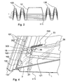
- FIG. 2 An example shows Fig. 2 , In Fig. 2 schematically five stacked plastic carrier 1 in the direction of the transverse edge 111 are shown. As based on Fig. 2 can be seen, both the beads 100 are both sides, as well as the increase 12 on top and Bottom each formed complementary, so that the plastic carrier 1 can stack each other.
- the plastic carrier is therefore made of a thermoplastic molding material.
- plastics selected from polyethylene, polypropylene, polyvinyl chloride, polystyrene, impact-modified polystyrene (HiPS), acrylonitrile-butadiene-styrene copolymers (ABS), acrylonitrile-styrene-acrylate copolymers (ASA), methacrylate-acrylonitrile-butadiene-styrene Copolymers (MABS), styrene-butadiene block copolymers, polyamide, polyethylene terephthalate (PET), polyethylene terephthalate glycol (PETG), polybutylene terephthalate (PBT), polyoxymethylene (POM), polycarbonate (PC), polymethyl methacrylate (PMMA), poly (ether) s
- Particularly preferred plastics are polyamides.
- plastics mentioned can be used in pure form or as a mixture with plastic-compatible auxiliaries.
- plastics provided with fibrous or particulate fillers are used.
- thermoplastic molding composition is still shaping with a proportion of fibrous and / or particulate fillers of up to 70 weight percent, preferably in the range of 10 to 60 weight percent, particularly preferably 20 to 50 weight percent shaping, in particular by injection molding or injection-compression molding for the preparation of the inventive comparatively large-area plastic carrier 1 can be processed.
- the high proportion of fibrous and / or particulate fillers increases the strength and longevity of the plastic carrier 1.
- pigments and / or stabilizers are added to the thermoplastic molding composition to improve the weathering resistance and / or the fire properties.
- These pigments and / or stabilizers may form part of the aforementioned fibrous or particulate fillers or be added in addition to the fibrous or particulate fillers.
- Particularly suitable fillers are glass fibers, glass beads, mineral fillers, or so-called nanoparticles.
- polyamides are in principle all known polyamides.
- polyamides derived from lactams having 7 to 13 ring members such as polycaprolactam, polycapryllactam and polylaurolactam, as well as polyamides obtained by reacting dicarboxylic acids with diamines.
- alkanedicarboxylic acids having 6 to 12, in particular 6 to 10 carbon atoms and aromatic dicarboxylic acids can be used.
- Particularly suitable diamines are alkanediamines having 6 to 12, in particular 6 to 8, carbon atoms, and m-xylylenediamine, di (4-aminophenyl) methane, di- (4-aminocyclohexyl) -methane, di- (4-amino-3-methyl cyclohexyl) methane, isophoronediamine, 1,5-diamino-2-methyl-pentane, 2,2-di- (4-aminophenyl) -propane or 2,2-di- (4-aminocyclohexyl) -propane.
- Preferred polyamides are, in particular, polyhexamethylene adipamide (PA 66) and polyhexamethylene sebacamide (PA 610), polycaprolactam (PA 6) and copolyamides 6/66, in particular with a proportion of 5 to 95% by weight of caprolactam units.
- the polyamide is preferably selected from PA 6, PA 66 and copolyamide 6/66; PA 6 is most preferred.
- polystyrene resin Suitable polyamides are obtainable from ⁇ -aminoalkyl nitriles such as aminocapronitrile (PA 6) and adiponitrile with hexamethylenediamine (PA 66) by so-called direct polymerization in the presence of water, such as in the DE-A 10313681 .
- PA 6 aminocapronitrile
- PA 66 adiponitrile with hexamethylenediamine
- polyamide 46 which are e.g. are obtainable by condensation of 1,4-diaminobutane with adipic acid at elevated temperature (polyamide 46).
- polyamides which are obtainable by copolymerization of two or more of the abovementioned monomers, or mixtures of a plurality of polyamides, the mixing ratio being arbitrary.
- the triamine content is less than 0.5, preferably less than 0.3 wt .-% (see EP-A 299 444 ).
- the production of partially aromatic copolyamides with a low triamine content can according to the in the EP-A 129 195 and 129 196 described method.
- polyamides and their preparation are known, for example from Ullmanns Encyklopadie der Technischen Chemie, 4th Edition, Vol. 19, pp. 39-54, Verlag Chemie, Weinheim 1980 ; Ullmanns Encyclopedia of Industrial Chemistry, Vol. A21, p. 179-206, VCH Verlag, Weinheim 1992 ; Stoeckhert, Kunststofflexikon, 8th edition, p. 425-428, Carl Hanser Verlag Kunststoff 1992 (Keyword “polyamides” and following), as well as Saechtling, plastic paperback, 27th edition, Carl Hanser-Verlag Kunststoff 1998, pages 465-478 ,
- the preparation of the preferred polyamides PA6, PA 66 and copolyamide 6/66 is briefly discussed below.
- the polymerization or polycondensation of the starting monomers to give the polyamide is preferably carried out by the usual methods.
- the polymerization of caprolactam for example, according to the in the DE-A 14 95 198 and DE-A 25 58 480 described continuous processes.
- the polymerization of AH salt to produce PA 66 can be carried out by the usual batch process (see: Polymerization Processes pp. 424-467, especially pp. 444-446, Interscience, New York, 1977 ) or according to a continuous process, eg according to EP-A 129 196 , respectively.
- chain regulators are, for example, triacetonediamine compounds (see WO-A 95/28443 ), Monocarboxylic acids such as acetic acid, propionic acid and benzoic acid, dicarboxylic acids such as adipic acid, sebacic acid, cyclohexane-1,4-dicarboxylic acid, isophthalic acid and terephthalic acid, and also bases such as hexamethylenediamine, benzylamine and 1,4-cyclohexyldiamine.
- Triacetonediamine compounds see WO-A 95/28443
- Monocarboxylic acids such as acetic acid, propionic acid and benzoic acid
- dicarboxylic acids such as adipic acid, sebacic acid, cyclohexane-1,4-dicarboxylic acid, isophthalic acid and terephthalic acid
- bases such as hexamethylenediamine, benzylamine and 1,4-cyclohexy
- the resulting polymer melt is discharged from the reactor, cooled and granulated.
- the granules obtained can be subjected to a postpolymerization, which usually takes 2 to 24 hours. This is done in a conventional manner by heating the granules to a temperature T below the melting temperature Ts or crystallite melting temperature T k of the polyamide. As a result of the postpolymerization, the final molecular weight of the polyamide (measurable as the viscosity number VZ, see information on the VZ below) is established.
- Suitable polyamides generally have a viscosity number VZ of 50 to 250, preferably 70 to 200 and particularly preferably 80 to 150 ml / g, determined according to ISO 307 EN on a 0.5 wt .-% solution of the polyamide in 96 wt. -% sulfuric acid at 25 ° C. These viscosity numbers correspond to high molecular weights.
- Polyamides which are particularly suitable for the present invention are glass-fiber-reinforced, highly flowable and heat-resistant polyamides, as described, for example, in US Pat WO 2006/042705 , Particularly suitable is an Ultramid® "high speed" from BASF SE.
- thermoforming plates are first produced by extrusion from the selected plastics. These are then heated in the so-called thermoforming process - e.g. with IR emitters - and reshaped in a three-dimensional thermoforming tool.
- thermoplastic materials In order to produce complex three-dimensional components, such as the plastic carrier according to the invention made of thermoplastic materials, injection molding in particular has proven itself. Due to the size of the component, it is preferable to use tools with hot runner systems.
- an injection molding process with cascade control can also be used.
- the plastic is injected through a plurality of nozzles arranged one behind the other in the direction of flow of the plastic.
- the control of the injection of the plastic takes place in such a way that the plastic is injected at the time by a nozzle, when the nozzle is covered by the plastic, which was injected from the arranged in the flow direction of the injected plastic nozzle in front.
- the Injection of the plastic is thus offset in time. Since the flow path to be covered by the plastic is thus limited despite the size of the component, larger components can be reduced despite the smaller wall thickness.
- the tool is not completely closed at the beginning.
- the tool gap which must flow through the plastic melt, thereby has a greater height, resulting in a lower pressure loss.
- the complete closing of the tool in this process only when the melt was partially or completely injected into the tool.
- the embossing phase can take place on the one hand by the movement of a tool half or on the other hand by the use of movable tool inserts, which are e.g. hydraulically controlled.
- Another special method with which, especially in the case of large-area components, the required injection pressure as well as the delay can be reduced is the use of physical or chemical blowing agents for injection molding or injection-compression molding.
- each roof has a more or less pronounced unevenness. In on-roof modules, this has so far been compensated by the adjustment of the roof hooks, in common in-roof systems by leveling the substructure.
- a plastic carrier part according to the invention can in particular also be designed to be twistable.
- the above-mentioned plastics in particular fiber-reinforced polyamides, are suitable.
- Polyamides are characterized by high elasticity for thermoplastics, which improves the twistability.
- the longitudinal directions parallel or substantially parallel are realized in particular by the parallel beads 100.
- a torsion about an axis along the longitudinal direction of the beads 100 or more generally the rainwater discharge elements 10 take place. This allows the compensation of a height difference of a substructure below the plastic support 1 of up to 10 mm.
- This value refers to a plastic carrier 1 for a module of size 1,685 mm x 993 mm.
- a high risk factor for roof-integrated photovoltaic systems is the cable routing and the associated danger of crushing the cable.
- the cable may be pinched between the substructure and the module.
- the photovoltaic modules 3 can be securely connected to each other.
- the recess is designed as formed in the beads 100, open at the top cable channel 101.
- the cable channel 101 But interrupts only an upper part of the beads 100, so that it is avoided that run off rainwater running through the cable channel 101 and under the overlapping next to each other attached plastic support 1 and can penetrate into the roof.
- the cable channel 101 extends above the ground plane 107 of the plastic carrier on which the water flows. Accordingly, in a further development of the invention, at least one cable guide element, preferably in the form of a half-open channel, is provided in the plastic carrier 1, which extends above a base plane 107 of the plastic carrier 1.
- the plastic carrier 1 allows the use of a frameless module, in particular designed as a double glass module.
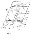
- FIG. 3 A view of a photovoltaic module 3 according to an embodiment of the invention is shown in FIG Fig. 3 shown.
- Fig. 3 shows the photovoltaic module 3 in a plan view of the front 30, so the photovoltaically active side.
- the photovoltaic module 3 comprises a glass plate 32 as a support or cover of the photoactive layer of the module 3
- the glass plate 32 is shown transparent for purposes of illustration to make the rear-mounted fasteners visible.
- connection cables 310 are shown, which are connected to a junction box 312. These connection cables 310 are inserted in the installation of the photovoltaic module 3 on the plastic carrier in the cable channels 101. During the subsequent lateral displacement of the photovoltaic module 3 for locking on the plastic carrier 1, it is thus avoided that the connection cables 310 between the module and the plastic carrier 1 are squeezed and damaged.
- the photovoltaic module according to the invention is characterized by mounted on the back of 31, preferably glued module holder 33, which are used simultaneously for attachment to the plastic substrate 1.
- module holder 33 By the manner of attachment, or the design of the module holder with locking elements no module frame is no longer necessary - the typical tasks of the module frame (attachment points and stiffening of the module) are taken from the module holders 33 and the later explained attachment to the plastic substrate 1.
- Each module holder 33 is glued with at least one adhesive surface 330 on the back 31.
- the back side 31, as well as the front side 30 is formed by a respective glass sheet, wherein the photoactive layer is disposed between the glass sheets.
- the photovoltaic module 3 is a frameless double-glass module.
- the photovoltaic module 3 has latching elements 35, 37 corresponding to the latching elements 20, 22 of the plastic carrier 1.
- the latching direction 38 is at the in Fig. 3
- locking lugs 35 are provided as latching elements 35, which protrude transversely to the latching direction 38 from the main body of the module holder 33.
- the locking lugs 35 locking surfaces 350 which are preferably parallel to the front 30 or back 31 of the photovoltaic module, but at least define support points for a corresponding locking element of the plastic support 1, which is a vertical movement in the direction perpendicular to Block front 30.
- the locking surfaces 350 have a component of the surface normal, which is parallel to the direction of the surface normal of the front 30 or the back 31, to block in contact with a locking element of a holder movement in the direction of this surface normal.
- the hooks 37 have a blocking surface 370 lying transversely to the latching direction 38, as well as a guide surface 371 running obliquely to the latching direction 38 and thus also obliquely to the surface of the rear side 31.
- the latching hooks 37 are mounted so resiliently that they can be moved in the direction transverse to the back 31.
- the hooks 37 are each double, wherein the hooks are oriented in opposite directions, or mirror-symmetrical to each other.
- This arrangement of the locking elements allows the photovoltaic module 3 by placing and subsequent lateral displacement on a support with corresponding locking means, in particular the plastic carrier 1 to lock, due to the mirror-symmetrical arrangement of the hook 37, the locking by lateral displacement optionally along two opposite locking directions 38 can take place.
- the latching direction 38 is in Fig. 3 shown as a double arrow.
- the latching in the lateral direction is effected by abutment of the blocking surfaces 370 on corresponding, opposite blocking surfaces of the respective carrier, so that each of the blocking surfaces 371 of the two hooks 37 each blocks a movement in a lateral direction.
- the resilient mounting of the hook 37 and its guide surfaces 371 allow the trailing in the direction of movement 38 trailing hook 37 is lifted by sliding the inclined guide surface 371 on an element of the carrier and can spring back after passing the locking surface of the carrier, so that the Locking surfaces of the hook and the carrier face.
- the resilient support of the hook 37 is provided by a leaf spring arm 372.
- the module carrier 33 made of plastic
- the locking elements 35, 37 including the Blattfederarms 372 can be made in one piece in a simple manner.
- the hooks 37 in the direction along the front or back 30, 31 form movable.
- a handle 39 is formed on the module carriers, or, conversely, the module carriers 33 are designed as handles 39.
- Fig. 4 shows starting from the in Fig. 1 and 3 shown elements on the basis of an enlarged view, a first method step for fixing a photovoltaic module 3 on the plastic substrate.
- the plastic carrier 1 has in a further development of the invention a specially designed module-off device. This serves for the secure positioning of the photovoltaic module 3 before the actual fastening step. After filing the photovoltaic module 3 can be used without risk.
- This device is advantageous over conventional mounting systems, since in such systems often installers are required for installation to hold a module on the one hand and on the other hand to secure.
- Attachment with the edge 300 are placed on the shelf 105, so that the edge 300 comes into contact with the abutting surface 105 adjacent bearing edge 103.
- the abutment edge 103 is positioned so that the photovoltaic module 3 in contact with this edge and shelf on the shelf surface 105 in a defined initial position for the lateral displacement of the module along the plastic support 1 for mutual locking of the locking elements 20, 22, 35, 37 of plastic carrier 1 and photovoltaic module 3 comes to rest.
- the storage edge 103 and the storage area 105 are also in Fig. 1 located.
- the defined starting position exists as in Fig. 4 can be seen, that the locking lugs 35 of the module carrier 33 are seen in the direction of displacement in front of the corresponding locking elements 20 of the plastic carrier 1 are arranged.
- Fig. 5 shows for a more detailed explanation of the locking and fixing of the photovoltaic module 3 on the plastic support a section of the photovoltaic installation system with the latched photovoltaic module.
- the locking elements 20 are, as well as in Fig. 4 can be seen, projections or recesses on a formation 122, under which, or in which then the locking lugs 35 are pushed when inserted into the Verrastungsposition.
- On the formation 122 and the mounting points 18 are arranged.
- Fig. 5 is also a through to detect the mounting points 18 screwed into the roof substructure fixing screw 180.
- the photovoltaic modules 3 are further biased in the mounted end position by spring force, which prevents subsequent rattling by wind influence.
- a spring 181 is attached to it, which biases the photovoltaic module 3 in the vertical direction and thus prevents later rattling by wind on the roof.
- the latching in the direction of the latching direction 38, or in the horizontal direction is, as already mentioned above, effected by abutment of the locking surface 370 of the hook 37 lying transversely to the latching direction 38 against a corresponding blocking surface of the plastic carrier 1.
- This corresponding blocking surface forms a latching element 22 for horizontal locking of the photovoltaic module 3.
- this blocking surface can be formed in a simple manner by a side wall 1001 of a bead 100.
- the hook 37 located behind in the latching direction is moved over the bead 100, wherein the guide surface 371 is lifted during the displacement by the bead 100 under elastic deformation of the leaf spring arm 372, so that the hook 37 slides over the bead 100.
- the hook 37 In the latching position, the hook 37 is moved over the bead 100, so that the spring force of the Blattfederarms 372 then the hook 37 back in his in Fig. 5 shown vertical starting position thus moves the locking surface 370 in opposition to the side wall 1001st the beading brings 100.
- the locking surface 370 of the hook 37 prevents movement of the module in a horizontal direction and the other, in Fig. 5 not shown, opposing hooks 37, the movement in the opposite direction, so that by cooperation of both hooks 37 of a module support 33 with the side walls 1001 of the plastic support 1, a horizontal locking, so that a locking in the direction parallel to the surface of the glass pane is effected.
- An inventive photovoltaic installation system with a plastic support 1 and a photovoltaic module 3 is thus characterized in general by the fact that locking elements 20, 22, 35, 37 are provided on plastic support 1 and photovoltaic module 3, which the locking of the Photovoltaic module 3 on the plastic substrate 1 by placing the photovoltaic module 3 in an initial position and lateral displacement of the photovoltaic module 3 on the plastic substrate 1 to a in Fig. 5 shown locking position a locking of the photovoltaic module 3 is effected both in the horizontal direction along the surface of the glass, or along the front or back, as well as perpendicular thereto, so that a complete locking of the photovoltaic module 3 is achieved in all directions.
- the horizontal displacement of the photovoltaic module 3 for locking can be used in a particularly advantageous manner as anti-theft device.
- the module assembly by horizontal telescoping from module to substructure allows a simplified anti-theft of the entire module field.
- There at Side by side mounted plastic supports the narrow gap between the photovoltaic modules 3, a displacement of a single module of the module field is not allowed if the required path for unlocking the photovoltaic module 3 is longer than the gap width between the photovoltaic modules, it is sufficient to provide the respective outer modules with a kind of anti-theft device.
- each module must be provided with an anti-theft device.
- the width of the photovoltaic module measured in Verrastungscardi 38 is greater than the width of the plastic carrier 1 in this direction minus the displacement between the initial position and the Verrastungsposition. This ensures that when mounting multiple modules on the plastic supports, the gap between the photovoltaic modules 3 is less than the displacement.
Landscapes
- Architecture (AREA)
- Civil Engineering (AREA)
- Structural Engineering (AREA)
- Engineering & Computer Science (AREA)
- Chemical & Material Sciences (AREA)
- Chemical Kinetics & Catalysis (AREA)
- Health & Medical Sciences (AREA)
- Medicinal Chemistry (AREA)
- Polymers & Plastics (AREA)
- Organic Chemistry (AREA)
- Roof Covering Using Slabs Or Stiff Sheets (AREA)
- Photovoltaic Devices (AREA)
- Fittings On The Vehicle Exterior For Carrying Loads, And Devices For Holding Or Mounting Articles (AREA)
Description
- Die Erfindung betrifft Photovoltaik-Anlagen im Allgemeinen. Im Speziellen betrifft die Erfindung ein System zur Installation von Photovoltaik-Anlagen auf Dächern.
- Aus dem Stand der Technik sind eine Vielzahl von Halterungen zur Montage von Photovoltaik-Modulen auf Hausdächern bekannt. Eine gattungsgemässe Halterung, die den Oberbegriff des Anspruchs 1 offenbart, ist aus der
EP 1 833 098 bekannt. - Bei den bisherigen Befestigungssystemen werden die Photovoltaik-Module vielfach mit Verschraubungsklemmen an der Halterung befestigt. Das Verschrauben ist dabei vergleichsweise zeitaufwändig. Auch sind bei üblichen Halterungen im Allgemeinen eine Vielzahl von Einzelteilen, unter anderem die vorstehend genannten Verschraubungsklemmen für die Montage erforderlich.
- Die Montage stellt sich entsprechend aufwändig dar. Dies führt dazu, dass die Montagekosten einen nicht vernachlässigbaren Anteil an den Investitionskosten für eine Photovoltaik-Anlage ausmachen. So kann man auch bei Großprojekten derzeit mit mehr als 15% Anteil der Montagekosten an der Gesamt-Investitionssumme rechnen. Hierbei fällt zusätzlich ins Gewicht, dass dieser Anteil bei sinkenden Modulpreisen auch noch steigt.
- Ein weiterer Nachteil bisheriger, auf Dächern installierter Photovoltaik-Anlagen ist das durch die Halterung entstehende zusätzliche Gewicht. Unter Umständen kann damit das Gesamtgewicht der Anlage so groß werden, dass die zulässige Gesamtlast der Dachkonstruktion überschritten wird. In diesem Fall müsste dann die Dachkonstruktion verstärkt werden.
- Der Erfindung liegt daher die Aufgabe zugrunde, eine schnell und einfach zu montierende und dabei auch leichte Photovoltaik-Anlage bereitzustellen. Diese Aufgabe wird durch den Gegenstand der unabhängigen Ansprüche gelöst. Vorteilhafte Ausführungsformen und Weiterbildungen der Erfindung sind in den jeweiligen abhängigen Ansprüchen angegeben.
- Erfindungsgemäß wird ein dachintegriertes Photovoltaik-System mit Kunststoff-Trägern vorgeschlagen.
- Bei dem dachintegrierten Photovoltaik-System mit Kunststoff-Trägern handelt es sich um eine optimierte Lösung insbesondere für große Photovoltaik-Anlagen. Weiterhin ist die Erfindung auch besonders für eine begleitende Dachsanierung, wie etwa von Faserzement-Dächern geeignet, wenn im Zuge der Dachsanierung die Dacheindeckung ausgetauscht wird.
- Das erfindungsgemäße Photovoltaik-System ist im Wesentlichen zweiteilig. Ein Teil bildet ein Kunststoff-Träger, der andere Teil ist das Photovoltaik-Modul. der Kunststoff-Träger kann direkt auf einer Dachunterkonstruktion befestigt werden, so dass eine zusätzliche Dacheindeckung entfallen kann. Auf diese Weise wird der gesamte, die Dachunterkonstruktion belastende Dachaufbau erheblich leichter. Einen zusätzlichen Beitrag leistet dabei der Kunststoff-Träger, der aufgrund des Materials im Allgemeinen entsprechend leichter ist, als etwa Metallträger entsprechender Abmessungen.
- Weiterhin zeichnet sich die Erfindung dadurch aus, dass die Photovoltaik-Module verschraubungsfrei, im Speziellen mittels eines Rast- oder Bajonett-Verschlusses auf dem Kunststoff-Träger befestigbar sind. Nachdem die Kunststoff-Träger also auf dem Dach befestigt sind, können die Photovoltaik-Module werkzeugfrei durch einen Rastmechanismus am jeweiligen Kunststoff-Träger befestigt werden.
- Die Erfindung wird nachfolgend anhand von Ausführungsbeispielen und unter Bezugnahme auf die beigeschlossenen Zeichnungen näher erläutert. Dabei verweisen gleiche Bezugszeichen in den Zeichnungen auf gleiche oder entsprechende Elemente. Es zeigen:
- Fig. 1
- eine Ansicht des Kunststoff-Trägers,
- Fig. 2
- mehrere gestapelte Kunststoff-Träger,
- Fig. 3
- eine Ansicht eines Photovoltaik-Moduls,
- Fig. 4
- ausgehend von den in
Fig. 1 und3 gezeigten Elementen anhand einer vergrößerten Ansicht einen ersten Verfahrensschritt zur Fixierung eines Photovoltaik-Moduls auf dem Kunststoff-Träger 1, - Fig. 5
- einen Ausschnitt eines Photovoltaik-Installationssystems mit auf dem Kunststoff-Träger verrastetem Photovoltaik-Modul.
- In
Fig. 1 ist eine Ansicht auf die Oberseite 14 eines Kunststoff-Trägers 1, nachfolgend auch als Wanne bezeichnet, für ein daran zu befestigendes Photovoltaik-Modul gezeigt. Als Oberseite 14 wird dabei im Sinne der Erfindung diejenige Seite des Kunststoff-Trägers 1 bezeichnet, auf welcher das Photovoltaik-Modul befestigt wird und welche beim Einbau in eine Dachfläche nach oben weist. Der erfindungsgemäße Kunststoff-Träger 1, wie er als Beispiel inFig. 1 gezeigt ist, ist als einteiliges ausgeformtes Kunststoffelement mit rechteckigem oder quadratischem Umriss ausgebildet. Der Kunststoff-Träger 1 hat die Gestalt eines flachen oder flächigen Bauteils, bei welchem Strukturen aus einem flachen, plattenförmigen, eine Grundebene 107 bildenden Bereich hervorragen. Entlang einer ersten lateralen Richtung weist der Kunststoff-Träger 1 Regenwasser-Abführelemente 10 auf, welche bei Schrägstellung des Kunststoff-Trägers 1 Regenwasser entlang dieser lateralen Richtung, beziehungsweise in Richtung des Gefälles leiten. Insbesondere ist es zweckmäßig, entlang einer Kante 110 des Kunststoff-Trägers 1 verlaufende, aus der Grundebene 107 herausragende, langgestreckte Regenwasser-Abführelemente 10 vorzusehen. Demgemäß wird dann das Regenwasser in Richtung entlang dieser Kante geführt. Die Kunststoff-Träger 1 werden dann zweckmäßig so auf einem Dach montiert, dass entlang dieser Kante 110 verglichen mit den angrenzenden Kanten, nachfolgend als Querkanten 111 bezeichnet, das größere Gefälle vorliegt. Vorzugsweise verläuft die Richtung des Gefälles dabei entlang der Kante 110. Der Kunststoff-Träger 1 weist weiterhin eine Ausformung in Gestalt einer Erhöhung 12 auf der Oberseite 14 auf, deren Rand 120 in einem Abstand zur Umrandung 11 des Kunststoff-Trägers 1 verläuft. Auf der Erhöhung 12 sind Montagepunkte 18 angeordnet, um an diesen Punkten Befestigungsmittel durch den Kunststoff-Träger 1 hindurch zu führen und an einer Unterkonstruktion zu befestigen. Außerdem weist der Kunststoff-Träger 1 weiterhin Rastelemente 20, 22 zur rastenden Fixierung eines Photovoltaik-Moduls auf. Diese ermöglichen insbesondere in Verbindung mit Rastelementen eines passenden Photovoltaik-Moduls die Fixierung des Photovoltaik-Moduls ohne weitere, Werkzeug erfordernde Maßnahmen, wie beispielsweise Verschraubungen. - Als Montagepunkte 18 können insbesondere Durchgangsöffnungen für das Durchführen von Verschraubungen dienen. Die Erhöhung 12 in der Mitte des Kunststoff-Trägers und die Anordnung der Montagepunkte auf dieser bewirkt, dass Regenwasser am Rand der 120 der Erhöhung entlang und damit um die Montagepunkte 18 herum geleitet wird. Damit wird in sehr einfacher Weise eine Regenwasser-Abdichtung für die Montagepunkte 18 erzielt.
- Wie weiterhin anhand von
Fig. 1 zu erkennen ist, sind die Montagepunkte 18 zur Umrandung 11 nach innen versetzt angeordnet. Vorzugsweise beträgt dabei der Abstand eines Montagepunkts 18 zur Umrandung 11 mindestens ein Sechstel, vorzugsweise mindestens ein Fünftel der Breite des Kunststoff-Trägers 1. Dies bewirkt gegenüber einer randseitigen Montage, dass die Montagepunkte 18 beim Aneinandersetzen der Kunststoffträger auf dem Dach möglichst gleichmäßig verteilt werden, was für eine bessere Verteilung der Kräfte bei auf die montierten Module wirkenden Sog- und/oder Druckmomenten. - Um Sog- und Druckkräfte besser ableiten zu können, ist insbesondere vorgesehen, wie bei der in
Fig. 1 gezeigten Ausführungsform die Rastelemente 20, welche vertikale Kräfte aufnehmen, nahe an den Montagepunkten 18 anzuordnen. Bei der inFig. 1 gezeigten Ausführungsform sind die Rastelemente 20 direkt neben den Montagepunkten angeordnet. Der Kraftfluss des Systems wird damit so ausgelegt, das eine auftretende Druck-/Soglast direkt - und somit optimal - in die Dachunterkonstruktion eingeleitet wird. Bei heute üblichen Auf-Dach-Systemen befindet sich der Modulbefestigungspunkt demgegenüber typischerweise jeweils außen am Modulrahmen und somit weit weg von dem Krafteinleitungspunkt in die Unterkonstruktion. Um eine optimale Weiterleitung von Sog- und Drucklasten in die Dachunterkonstruktion zu ermöglichen, sind daher, ohne Beschränkung auf die spezielle inFig. 1 gezeigte Ausführungsform der Erfindung Rastelemente 20 zur Arretierung in Richtung senkrecht zur Oberseite eines Photovoltaik-Moduls 3, beziehungsweise senkrecht zur Oberseite des Kunststoff-Trägers 1 vorgesehen, welche in einem Abstand von höchstens einem Sechstel, vorzugsweise von höchstens einem Zehntel der längsten Seitenabmessung des Kunststoff-Trägers 1 vom nächstliegenden Montagepunkt 18 entfernt angeordnet sind. - Besonders bevorzugt wird, wie auch in
Fig. 1 dargestellt, eine Erhöhung 12 in Gestalt einer Hochsicke 121, welche eine Öffnung 16 im Kunststoff-Träger 1 umrahmt. Die Öffnung 16 sorgt für eine gute Hinterlüftung der Photovoltaik-Module. Zudem wird das Gewicht des Kunststoff-Trägers 1 reduziert und Material eingespart. - Mit anderen Worten sind also die vorzugsweise vier Montagepunkte 18, insbesondere Verschraubungspunkte des Kunststoff-Trägers 1 in eine Hochsicke gelegt, welche außerhalb der Wasserführung liegt. Insbesondere können die Montagepunkte 18 so angeordnet sein, dass diese zusätzlich durch das später aufgesetzte Photovoltaik-Modul verdeckt und so optimal vor Regen- und Spritzwasser geschützt sind.
- Generell sind die Regenwasser-Abführelemente 10 so ausgebildet, dass schräg ablaufendes Regenwasser in Richtung des Gefälles, also in Richtung entlang einer Seite des Kunststoff-Trägers geführt wird und somit nicht seitlich ablaufen kann. Demgemäß kann mit den erfindungsgemäßen Kunststoff-Trägern 1 eine regendichte Dachabdichtung erzielt werden.
- Um eine regendichte Abdichtung beim Aneinandersetzen der Kunststoff-Träger 1 zu erhalten, sind in Weiterbildung der Erfindung beiderseitig der Erhöhung am Rand des Kunststoff-Trägers 1 Sicken 100 als Regenwasser-Abführelemente 10 vorgesehen, deren Ober- und Unterseiten komplementär geformt sind, so dass sich zwei Kunststoff-Träger 1 seitlich versetzt mit ineinandergreifenden Sicken 100 aufeinandersetzen lassen. Die Sicken 100 verhindern dabei nicht nur, dass schräg zur Gefällerichtung laufendes Wasser seitlich von den Kunststoff-Trägern 1 ablaufen und damit in das Dach eindringen kann. Derartige beiderseitig vorhandene Sicken 100 ermöglichen auch eine wahlfreie Verlegerichtung bei der Montage auf dem Dach. Die Kunststoff-Träger 1 können also in horizontaler Richtung sowohl von rechts nach links, als auch in umgekehrter Richtung überlappend aufeinandergesetzt werden, was den Montageaufwand verringert.
- Die Wasserführung erfolgt also erfindungsgemäß direkt über den Kunststoff-Träger, ohne dass zusätzliche Maßnahmen (wie z. B. zusätzliche Rinnen oder Dichtungen) erforderlich sind. Dabei wird die Regensicherheit sowohl in horizontaler Richtung, als auch in vertikaler Richtung durch entsprechende Überlappungen - gemäß der Regeln für das Dachdeckerhandwerk - sichergestellt.
- Um die Regendichtheit in vertikaler Richtung, beziehungsweise in Richtung der Dachneigung sicherzustellen und die Kunststoffträger einfach entlang dieser Richtung überlappend aufeinandersetzen zu können, weist der Kunststoff-Träger 1 gemäß noch einer Weiterbildung der Erfindung an den Rändern mit den Querkanten 111 ebenfalls an Ober- und Unterseite komplementär geformte Ausformungen auf. Wie anhand von
Fig. 1 zu erkennen ist, ist auch diese Weiterbildung bei der abgebildeten Ausführungsform durch die Sicken 100, sowie gegebenenfalls weitere ausgeformte Elemente realisiert. - Die komplementären Ausformungen auf Vorder- und Rückseite des Kunststoff-Trägers 1 ermöglichen ein einfaches passgenaues Aneinandersetzen der Kunststoff-Träger 1 auf dem Dach. Die erste Modulwanne, beziehungsweise der erste Kunststoff-Träger 1 kann dabei auf dem Dach durch entsprechendes Vermessen positioniert werden. Alle weiteren Kunststoff-Träger 1 positionieren sich durch die seitliche, bzw. vertikale Überlappung selbsttätig, so dass sich der Messaufwand auf ein Minimum beschränkt. Der Messaufwand bei heute üblichen Auf-Dach-, oder InDach-Systemen ist demgegenüber wesentlich aufwändiger.
- Der Kunststoff-Träger 1 kann allgemein als Gleichteil ausgeführt sein, d. h. jeder Kunststoff-Träger 1 kann damit an einer beliebigen Stelle des Modulfeldes montiert werden. Dies ermöglicht eine einfache Installation der Kunststoff-Träger 1 und optimiert auch die Logistik in den Punkten Verpackung (jeder Träger 1 kann gleich verpackt werden) und Transport. Zu letzterem Punkt ist in Weiterbildung der Erfindung der Kunststoff-Träger 1 stapelbar und damit für den Transport platzsparend ausgebildet. Unter einem stapelbaren Kunststoff-Träger 1 wird dabei im Sinne der Erfindung ein Kunststoff-Träger mit Ausformungen verstanden, dessen Ober- und Unterseite zumindest teilweise komplementär sind, so dass beim Aufeinandersetzen eines Kunststoff-Trägers 1 mit dessen Unterseite auf die Oberseite eines weiteren Kunststoff-Trägers 1 mit fluchtenden Kanten die Gesamthöhe der so aufeinandergestapelten beiden Kunststoff-Träger geringer ist als die doppelte Höhe eines einzelnen Kunststoff-Trägers 1.
- Ein Beispiel hierzu zeigt
Fig. 2 . InFig. 2 sind schematisch fünf aufeinandergestapelte Kunststoff-Träger 1 in Blickrichtung auf die Querkante 111 dargestellt. Wie anhand vonFig. 2 zu erkennen ist, sind sowohl die Sicken 100 beidseitig, als auch die Erhöhung 12 an Ober- und Unterseite jeweils komplementär ausgebildet, so dass sich die Kunststoff-Träger 1 aufeinanderstapeln lassen. - Als Kunststoff ist in den erfindungsgemäßen Verfahren grundsätzlich jedes thermoplastische verarbeitbare Polymer einsetzbar. Gemäß einer bevorzugten Weiterbildung der Erfindung ist der Kunststoff-Träger daher aus einer thermoplastischen Formmasse gefertigt. Insbesondere geeignet sind ein oder mehrere Kunststoffe ausgewählt aus Polyethylen, Polypropylen, Polyvinylchlorid, Polystyrol, schlagfest modifiziertem Polystyrol (HiPS), AcrylnitrilButadien-Styrol-Copolymeren (ABS), Acrylnitril-Styrol-Acrylat-Copolymeren (ASA), Methacrylat-AcrylnitrilButadien-Styrol-Copolymeren (MABS), Styrol-Butadien-Blockcopolymeren, Polyamid, Polyethylenterephthalat (PET), Polyethylenterephthalatglycol (PETG), Polybutylenterephthalat (PBT), Polyoxymethylen (POM), Polycarbonat (PC), Polymethylmethacrylat (PMMA), Poly(ether)sulfonen, thermoplastisch verarbeitbarem Polyurethan (TPU) und Polyphenylenoxid (PPO).
- Besonders bevorzugte Kunststoffe sind Polyamide.
- Die genannten Kunststoffe können in reiner Form oder als Mischung mit kunststoffüblichen Hilfsstoffen eingesetzt werden. In einer bevorzugten Ausführungsform werden mit faserförmigen oder teilchenförmigen Füllstoffen versehene Kunststoffe eingesetzt.
- Es hat sich gezeigt, dass die thermoplastische Formmasse noch formgebend mit einem Anteil faserförmiger und/oder teilchenförmiger Füllstoffe von bis zu 70 Gewichtsprozent, vorzugsweise im Bereich von 10 bis 60 Gewichtsprozent, besonders bevorzugt 20 bis 50 Gewichtsprozent formgebend, insbesondere durch Spritzguss oder Spritzprägedruck zur Herstellung der erfindungsgemäßen, vergleichsweise großflächigen Kunststoff-Träger 1 verarbeitbar ist. Der hohe Anteil von faser- und/oder teilchenförmigen Füllstoffen erhöht dabei die Festigkeit und Langlebigkeit des Kunststoff-Trägers 1.
- Gemäß noch einer Weiterbildung werden der thermoplastischen Formmasse Pigmente und/oder Stabilisatoren zur Verbesserung der Witterungsbeständigkeit und oder der Brandeigenschaften beigemischt. Diese Pigmente und/oder Stabilisatoren können einen Anteil der vorgenannten faser- oder teilchenförmigen Füllstoffe bilden oder zusätzlich zu den faser- oder teilchenförmigen Füllstoffen hinzugegeben werden.
- Besonders geeignete Füllstoffe sind Glasfasern, Glaskugeln, mineralische Füllstoffe, oder so genannte Nanopartikel.
- Ganz besonders bevorzugte Kunststoffe sind glasfaserverstärkte Polyamide. Als Polyamide eignen sich prinzipiell alle bekannten Polyamide. In Betracht kommen beispielsweise Polyamide mit aliphatischem, teilkristallinem oder teilaromatischem sowie amorphem Aufbau jeglicher Art und deren Blends, einschließlich Polyetheramiden wie Polyetherblockamiden.
-
- Beispiele hierfür sind Polyamide, die sich von Lactamen mit 7 bis 13 Ringgliedern ableiten, wie Polycaprolactam, Polycapryllactam und Polylaurinlactam, sowie Polyamide, die durch Umsetzung von Dicarbonsäuren mit Diaminen erhalten werden.
- Als Dicarbonsäuren sind Alkandicarbonsäuren mit 6 bis 12, insbesondere 6 bis 10 Kohlenstoffatomen und aromatische Dicarbonsäuren einsetzbar. Hier seien Adipinsäure, Azelainsäure, Sebacinsäure, Dodecandisäure (=Decandicarbonsäure) und Terephthal- und/oder Isophthalsäure als Säuren genannt.
- Als Diamine eignen sich besonders Alkandiamine mit 6 bis 12, insbesondere 6 bis 8 Kohlenstoffatomen sowie m-Xylylendiamin, Di-(4-aminophenyl)methan, Di-(4-aminocyclohexyi)-methan, Di-(4-amino-3-methyl-cyclohexyl)-methan, Isophorondiamin, 1,5-Diamino-2-methyl-pentan, 2,2-Di-(4-aminophenyl)-propan oder 2,2-Di-(4-aminocyclohexyl)-propan.
- Bevorzugte Polyamide sind insbesondere Polyhexamethylenadipinsäureamid (PA 66) und Polyhexamethylensebacinsäureamid (PA 610), Polycaprolactam (PA 6) sowie Copolyamide 6/66, insbesondere mit einem Anteil von 5 bis 95 Gew.-% an Caprolactam-Einheiten.
- Bevorzugt ist das Polyamid ausgewählt aus PA 6, PA 66 und Copolyamid 6/66; PA 6 ist ganz besonders bevorzugt.
- Weitere geeignete Polyamide sind erhältlich aus ω-Aminoalkylnitrilen wie z.B. Aminocapronitril (PA 6) und Adipodinitril mit Hexamethylendiamin (PA 66) durch sog. Direktpolymerisation in Anwesenheit von Wasser, wie beispielsweise in der
DE-A 10313681 ,EP-A 1198491 undEP-A 922065 - Außerdem seien auch noch Polyamide erwähnt, die z.B. durch Kondensation von 1,4-Diaminobutan mit Adipinsäure unter erhöhter Temperatur erhältlich sind (Polyamid 46).
- Herstellungsverfahren für Polyamide dieser Struktur sind z.B. in den
EP-A 38 094 EP-A 38 582 EP-A 39 524 - Weitere Beispiele sind Polyamide, die durch Copolymerisation zweier oder mehrerer der vorgenannten Monomeren erhältlich sind, oder Mischungen mehrerer Polyamide geeignet, wobei das Mischungsverhältnis beliebig ist.
- Weiterhin haben sich solche teilaromatischen Copolyamide wie PA 6/6T und PA 66/6T als besonders vorteilhaft erwiesen, deren Triamingehalt weniger als 0,5, vorzugsweise weniger als 0,3 Gew.-% beträgt (siehe
EP-A 299 444 EP-A 129 195 129 196 - Die nachfolgende, nicht abschließende Aufstellung enthält die genannten, sowie weitere Polyamide im Sinne der Erfindung und die enthaltenen Monomeren:
- AB-Polymere:
- PA 6 ε-Caprolactam
- PA 7 Ethanolactam
- PA 8 Capryllactam
- PA 9 9-Aminopelargonsäure
- PA 11 11-Aminoundecansäure
- PA 12 Laurinlactam.
- AA/BB-Polymere:
- PA 46 Tetramethylendiamin, Adipinsäure
- PA 66 Hexamethylendiamin, Adipinsäure
- PA 69 Hexamethylendiamin, Azelainsäure
- PA 610 Hexamethylendiamin, Sebacinsäure
- PA 612 Hexamethylendiamin, Decandicarbonsäure
- PA 613 Hexamethylendiamin, Undecandicarbonsäure
- PA 1212 1,12-Dodecandiamin, Decandicarbonsäure
- PA 1313 1,13-Diaminotridecan, Undecandicarbonsäure
- PA 6T Hexamethylendiamin, Terephthalsäure
- PA MXD6 m-Xylylendiamin, Adipinsäure
- PA 61 Hexamethylendiamin, Isophthalsäure
- PA 6-3-T Trimethylhexamethylendiamin, Terephthalsäure
- PA 6/6T (siehe PA 6 und PA 6T)
- PA 6/66 (siehe PA 6 und PA 66)
- PA 6/12 (siehe PA 6 und PA 12)
- PA 66/6/610 (siehe PA 66, PA 6 und PA 610)
- PA 6I/6T (siehe PA 61 und PA 6T)
- PA PACSV1 12 Diaminodicyclohexylmethan, Laurinlactam
- PA 6I/6T/PACM wie PA 6I/6T + Diaminodicyclohexylmethan
- PA 12/MACMI Laurinlactam, Dimethyldiaminodicyclohexylmethan, Isophthalsäure
- PA 12/MACMT Laurinlactam, Dimethyldiaminodicyclohexylmethan, Terephthalsäure
- PA PDA-T Phenylendiamin, Terephthalsäure.
- Die Polyamide und ihre Herstellung sind bekannt, beispielsweise aus Ullmanns Encyklopädie der Technischen Chemie, 4. Auflage, Bd. 19, S. 39-54, Verlag Chemie, Weinheim 1980; Ullmanns Encyclopedia of Industrial Chemistry, Vol. A21, S. 179-206, VCH Verlag, Weinheim 1992; Stoeckhert, Kunststofflexikon, 8. Auflage, S. 425-428, Carl Hanser Verlag München 1992 (Stichwort "Polyamide" und folgende), sowie Saechtling, Kunststoff-Taschenbuch, 27. Ausgabe, Carl Hanser-Verlag München 1998, Seiten 465-478.
- Auf die Herstellung der bevorzugten Polyamide PA6, PA 66 und Copolyamid 6/66 wird nachfolgend kurz eingegangen. Die Polymerisation bzw. Polykondensation der Ausgangsmonomere zum Polyamid wird vorzugsweise nach den üblichen Verfahren durchgeführt. So kann die Polymerisation des Caprolactams beispielsweise nach den in der
DE-A 14 95 198 undDE-A 25 58 480 beschriebenen kontinuierlichen Verfahren erfolgen. - Die Polymerisation von AH-Salz zur Herstellung von PA 66 kann nach dem üblichen diskontinuierlichen Verfahren (siehe: Polymerization Processes S. 424-467, insbesondere S. 444-446, Interscience, New York,1977) oder nach einem kontinuierlichen Verfahren, z.B. gemäß
EP-A 129 196 - Bei der Polymerisation können übliche Kettenregler mitverwendet werden. Geeignete Kettenregler sind z.B. Triacetondiaminverbindungen (siehe
WO-A 95/28443 - Die erhaltene Polymerschmelze wird aus dem Reaktor ausgetragen, gekühlt und granuliert.
- Das erhaltene Granulat kann einer Nachpolymerisation unterworfen werden, die in der Regel 2 bis 24 Stunden dauert. Dies geschieht in an sich bekannter Weise durch Erwärmen des Granulats auf eine Temperatur T unterhalb der Schmelztemperatur Ts bzw. Kristallitschmelztemperatur Tk des Polyamids. Durch die Nachpolymerisation stellt sich das endgültige Molekulargewicht des Polyamids (messbar als Viskositätszahl VZ, siehe Angaben zur VZ weiter unten) ein. Geeignete Polyamide weisen im Allgemeinen eine Viskositätszahl VZ von 50 bis 250, vorzugsweise 70 bis 200 und besonders bevorzugt 80 bis 150 ml/g auf, bestimmt gemäß ISO 307 EN an einer 0,5 gew.-%igen Lösung des Polyamids in 96 gew.-%iger Schwefelsäure bei 25°C. Diesen Viskositätszahlen entsprechen hohe Molekulargewichte.
- Für die vorliegende Erfindung besonders geeignete Polyamide sind glasfaserverstärkte, hoch-fließfähige und wärmebeständige Polyamide, wie sie beispielsweise beschrieben werden in
WO 2006/042705 . Insbesondere geeignet ist ein Ultramid® "Highspeed" der BASF SE. - Als Herstellungsverfahren der erfindungsgemäßen Kunststoff-Träger kommen verschiedene Fertigungstechniken wie z.B. Thermoformen oder Spritzgießen in Frage. Im Falle vom Thermoformen werden aus den ausgewählten Kunststoffen zunächst im Extrusionsverfahren Platten hergestellt. Diese werden dann im sogenannten Thermoformprozess erwärmt - z.B. mit IR-Strahlern - und in einem dreidimensionalen Thermoformwerkzeug umgeformt.
- Um komplexe dreidimensionale Bauteile, wie die erfindungsgemäßen Kunststoff-Träger aus thermoplastischen Kunststoffen herzustellen, has sich insbesondere das Spritzgießen bewährt. Aufgrund der Bauteilgröße sind hier bevorzugt Werkzeuge mit Heißkanalsystemen zu verwenden.
- Durch die Verwendung einen Heißkanal-Verteilers, der die Kunststoffschmelze an verschiedene Düsen verteilt, kann der für die Werkzeugfüllung erforderliche Fließweg deutlich reduziert werden.
- Bei großflächigen Bauteilen kann auch ein Spritzgussverfahren mit Kaskadensteuerung zur Anwendung gelangen. Dabei wird der Kunststoff durch mehrere, in Fließrichtung des Kunststoffs hintereinander angeordnete Düsen eingespritzt. Die Steuerung der Einspritzung des Kunststoffs erfolgt dabei in der Weise, dass der Kunststoff erst zu dem Zeitpunkt durch eine Düse eingespritzt wird, wenn die Düse durch den Kunststoff, der aus der in Fließrichtung des eingespritzten Kunststoffs davor angeordneten Düse eingespritzt wurde, überdeckt ist. Die Einspritzung des Kunststoffs erfolgt also zeitlich versetzt. Da der durch den Kunststoff zurückzulegende Fließweg trotz der Bauteilgröße so begrenzt wird, können trotz geringer Wanddicke größere Bauteile reduziert werden.
- Ein weiteres Sonderverfahren, das sich insbesondere bei großflächigen Bauteilen bewährt hat, ist das Spitzprägen.
- Hier wird das Werkzeug zu Beginn nicht vollständig geschlossen. Der Werkzeugspalt, den die Kunststoffschmelze durchfließen muss, hat dadurch eine größere Höhe, was zu einem geringeren Druckverlust führt. Das vollständige Schließen des Werkzeugs erfolgt bei diesem Verfahren erst wenn die Schmelze teilweise oder komplett in das Werkzeug eingespritzt wurde. Die Prägephase kann dabei zum einen durch die Bewegung einer Werkzeughälfte erfolgen oder zum anderen durch die Verwendung von beweglichen Werkzeugeinsätzen, die z.B. hydraulisch angesteuert werden.
- Ein weiteres Sonderverfahren mit dem vor allem bei großflächigen Bauteilen zum einen der erforderliche Einspritzdruck als auch der Verzug reduziert werden können ist die Verwendung von physikalischen oder chemischen Treibmitteln für den Spritzguß oder das Spritzprägen.
- Mit den erfindungsgemäßen Kunststoff-Trägern kann gemäß einer Weiterbildung der Erfindung auch ein automatischer Toleranzausgleich erzielt werden. Jedes Dach hat eine mehr oder weniger ausgeprägte Unebenheit. Bei Auf-Dach-Modulen wird dies bisher durch die Justage der Dachhacken ausgeglichen, bei gängigen In-Dach-Systemen durch Nivellierung der Unterkonstruktion.
- Ein erfindungsgemäßes Kunststoff-Trägerteil kann aber insbesondere auch verwindbar ausgebildet sein. Um dies zu erzielen, sind die oben genannten Kunststoffe, insbesondere faserverstärkte Polyamide geeignet. Polyamide zeichnen sich durch für Thermoplaste hohe Elastizität aus, was die Verwindbarkeit verbessert. Weiterhin sind vorzugsweise, wie auch bei der in
Fig. 1 gezeigten Ausführungsform am Rand, beziehungsweise im Bereich der Umrandung 11 Ausformungen vorhanden, deren Längsrichtungen parallel oder im wesentlichen parallel verlaufen. Bei der dargestellten Ausführungsform werden diese Ausformungen insbesondere durch die parallel verlaufenden Sicken 100 realisiert. Auf diese Weise kann eine Torsion um eine Achse entlang der Längsrichtung der Sicken 100 oder allgemeiner der Regenwasser-Abführelemente 10 erfolgen. Damit wird der Ausgleich eines Höhenunterschieds einer Unterkonstruktion unterhalb des Kunststoff-Trägers 1 von bis zu 10 mm ermöglicht. Dieser Wert bezieht sich auf einen Kunststoff-Träger 1 für ein Modul der Größe 1.685 mm x 993 mm. - Ein hoher Risikofaktor bei dachintegrierten Photovoltaik-Systemen stellt die Kabelführung und die damit verbundene Quetschgefahr des Kabels dar. Beim Abstellen des Moduls oder direkt bei der Montage kann es zur Quetschung des Kabels zwischen Unterkonstruktion und Modul kommen. Um dies zu verhindern wird in Weiterbildung der Erfindung in den Kunststoff-Träger 1 eine Aussparung für die Kabelführung, integriert. Somit können die Photovoltaik-Module 3 sicher miteinander verbunden werden. Wie in
Fig. 1 dargestellt, ist die Aussparung als in die Sicken 100 eingeformter, oben offener Kabelkanal 101 ausgeführt. Der Kabelkanal 101 unterbricht aber nur einen oberen Teil der Sicken 100, so dass vermieden wird, dass abfließendes Regenwasser quer durch den Kabelkanal 101 ablaufen und unter die überlappend nebeneinander befestigten Kunststoff-Träger 1 geraten und in das Dach eindringen kann. Mit anderen Worten verläuft der Kabelkanal 101 oberhalb der Grundebene 107 des Kunststoff-Trägers, auf welcher das Wasser abfließt. Demgemäß ist in Weiterbildung der Erfindung im Kunststoff-Träger 1 zumindest ein Kabelführungselement, vorzugsweise in Gestalt eines halboffenen Kanals vorgesehen, welches oberhalb einer Grundebene 107 des Kunststoff-Trägers 1 verläuft. - Nachfolgend wird ein zum Kunststoff-Träger 1 passendes Photovoltaik-Modul gemäß einer Ausführungsform der Erfindung beschrieben.
- Allgemein ermöglicht der Kunststoff-Träger 1 die Verwendung eines rahmenlosen Moduls, insbesondere ausgestaltet als Doppelglasmodul.
- Eine Ansicht eines Photovoltaik-Modul 3 gemäß einer Ausführungsform der Erfindung ist in
Fig. 3 dargestellt.Fig. 3 zeigt dabei das Photovoltaik-Modul 3 in Aufsicht auf die Vorderseite 30, also die photovoltaisch aktive Seite. Das Photovoltaik-Modul 3 umfasst eine Glasscheibe 32 als Träger oder Abdeckung der photoaktiven Schicht des Moduls 3 Die Glasscheibe 32 ist zum Zwecke der Illustration durchsichtig dargestellt, um die rückseitig angebrachten Befestigungselemente sichtbar zu machen. - In
Fig. 3 sind die Anschlusskabel 310 dargestellt, welche mit einer Anschlussdose 312 verbunden sind. Diese Anschlusskabel 310 werden bei der Montage des Photovoltaik-Moduls 3 auf dem Kunststoff-Träger in die Kabelkanäle 101 eingelegt. Beim nachfolgenden lateralen Verschieben des Photovoltaik-Moduls 3 zur Arretierung auf dem Kunststoff-Träger 1 wird damit vermieden, dass die Anschlusskabel 310 zwischen Modul und Kunststoff-Träger 1 gequetscht und beschädigt werden. - Das erfindungsgemäße Photovoltaik-Modul zeichnet sich durch auf dessen Rückseite 31 befestigte, vorzugsweise aufgeklebte Modulhalter 33 aus, welche gleichzeitig zur Befestigung am Kunststoff-Träger 1 dienen. Durch die Art und Weise der Befestigung, beziehungsweise die Ausgestaltung der Modulhalter mit Rastelementen ist kein Modulrahmen mehr notwendig - die typischen Aufgaben des Modulrahmens (Befestigungspunkte und Versteifung des Moduls) werden von den Modulhaltern 33 und der später erläuterten Befestigung am Kunststoff-Träger 1 übernommen.
- Jeder Modulhalter 33 ist mit zumindest einer Klebefläche 330 auf der Rückseite 31 aufgeklebt. Vorzugsweise wird die Rückseite 31, ebenso wie die Vorderseite 30 durch je eine Glasscheibe gebildet, wobei die photoaktive Schicht zwischen den Glasscheiben angeordnet ist. Demgemäß stellt das Photovoltaik-Modul 3 ein rahmenloses Doppelglas-Modul dar.
- Derzeitige Standard-Module müssen an dem teilweise unhandlichen Modulrahmen gehandhabt werden. Demgegenüber sind in Weiterbildung der Erfindung an den Modulhaltern 33 Handgriffe 39 ausgebildet, mit welchen das Photovoltaik-Modul 3 einfach und sicher handhabbar ist.
- Das Photovoltaik-Modul 3 weist zu den Rastelementen 20, 22 des Kunststoff-Trägers 1 korrespondierende Rastelemente 35, 37 auf. Die Verrastungsrichtung 38 ist bei dem in
Fig. 3 gezeigten Beispiel entlang der Längsrichtung der Modulhalter 33. Um das Photovoltaik-Modul 3 in Richtung senkrecht zur Oberfläche zu arretieren, sind als Rastelemente 35 Rastnasen vorgesehen, welche quer zur Verrastungsrichtung 38 aus dem Grundkörper des Modulhalters 33 herausragen. Für die vertikale Arretierung weisen dabei die Rastnasen 35 Arretierungsflächen 350 auf, die vorzugsweise parallel zur Vorderseite 30 oder Rückseite 31 des Photovoltaik-Moduls liegen, jedenfalls aber Auflagepunkte für ein korrespondierendes Rastelement des Kunststoff-Trägers 1 definieren, welche eine vertikale Bewegung in Richtung senkrecht zur Vorderseite 30 blockieren. Mit anderen Worten weisen die Arretierungsflächen 350 eine Komponente der Flächennormalen auf, welche parallel zur Richtung der Flächennormalen der Vorderseite 30 oder der Rückseite 31 liegt, um in Kontakt mit einem Rastelement einer Halterung eine Bewegung in Richtung dieser Flächennormalen zu blockieren. - Als weitere Rastelemente 37 sind federnd gelagerte Haken vorgesehen. Die Haken 37 weisen eine quer zur Verrastungsrichtung 38 liegende Sperrfläche 370, sowie eine schräg zur Verrastungsrichtung 38 und damit auch schräg zur Fläche der Rückseite 31 verlaufende Führungsfläche 371 auf. Die Rasthaken 37 sind so federnd gelagert, dass diese sich in Richtung quer zur Rückseite 31 bewegen lassen.
- An jedem Modulträger 33 sind die Haken 37 jeweils doppelt vorhanden, wobei die Haken gegenläufig, beziehungsweise spiegelsymmetrisch zueinander orientiert sind. Diese Anordnung der Rastelemente erlaubt es, das Photovoltaik-Modul 3 durch Auflegen und anschließende seitliche Verschiebung auf einem Träger mit korrespondierenden Rastmitteln, wie insbesondere dem Kunststoff-Träger 1 zu arretieren, wobei aufgrund der spiegelsymmetrischen Anordnung der Haken 37 die Arretierung durch laterale Verschiebung wahlweise entlang zweier gegenläufiger Verrastungsrichtungen 38 erfolgen kann. Aus diesem Grund ist die Verrastungsrichtung 38 in
Fig. 3 als Doppelpfeil dargestellt. Die Verrastung in lateraler Richtung erfolgt dabei durch Anlage der Sperrflächen 370 an korrespondierende, gegenüberliegende Sperrflächen des jeweiligen Trägers, so dass jede der Sperrflächen 371 der beiden Haken 37 jeweils eine Bewegung in einer lateralen Richtung blockiert. Demgemäß ist durch Anlage der Sperrflächen 370 an feststehenden Elementen, wie etwa korrespondierende Sperrflächen einer Halterung eine Arretierung in Richtung parallel zur Fläche der Glassscheibe, beziehungsweise parallel zur Vorder- oder Rückseite des Photovoltaik-Moduls 3 bewirkbar. - Die federnde Lagerung der Haken 37 und dessen Führungsflächen 371 ermöglichen, dass der bei der Verrastung in Bewegungsrichtung 38 nachlaufende Haken 37 durch Gleiten der schrägen Führungsfläche 371 auf einem Element des Trägers angehoben wird und nach Passieren der Sperrfläche des Trägers zurückfedern kann, so dass sich die Sperrflächen des Hakens und des Trägers gegenüberstehen.
- Bei der in
Fig. 3 gezeigten Ausführungsform wird die federnde Halterung des Hakens 37 durch einen Blattfederarm 372 bereitgestellt. Sind, wie bevorzugt, die Modulträger 33 aus Kunststoff gefertigt, können die Rastelemente 35, 37 inklusive des Blattfederarms 372 in einfacher Weise einstückig hergestellt werden. Anders als inFig. 3 gezeigt, ist es auch denkbar, die Haken 37 in Richtung entlang der Vorder- oder Rückseite 30, 31 beweglich auszubilden. - Diese Montage und Arretierung auf dem Kunststoff-Träger 1 wird nachstehend anhand der weiteren Figuren noch genauer erläutert. Jedenfalls können die vorstehend beschriebenen Merkmale eines erfindungsgemäßen Photovoltaik-Moduls 3 ohne Beschränkung auf die wie folgt zusammengefasst werden:
- Das Photovoltaik-Modul 3 ist rahmenlos und weist zumindest eine die photovoltaisch aktive Schicht abdeckende Scheibe, vorzugsweise eine Glasscheibe auf, welche die Vorderseite des Photovoltaik-Moduls 3 bildet, wobei auf der gegenüberliegenden Rückseite des Photovoltaik-Moduls 3 Modulträger 33 aufgeklebt sind, und wobei die Modulträger 33 jeweils zwei Rastelemente (bei der in
Fig. 3 gezeigten Ausführungsform die Haken 37) an gegenüberliegenden Enden des Modulträgers 33 aufweisen, welche federnd beweglich ausgebildet sind, und wobei diese Rastelemente in entgegengesetzte Richtungen weisende Sperrflächen 370 aufweisen, und wobei die Modulträger 33, wie oben beschrieben, weitere Rastelemente (inFig. 3 im Speziellen die Rastnasen 35) mit Arretierungsflächen 350 aufweisen, wobei die Arretierungsflächen 350 eine Komponente der Flächennormalen aufweisen, welche parallel zur Richtung der Flächennormalen der Glasscheibe, oder der Vorder- oder Rückseite liegt, um in Kontakt mit einem Rastelement einer Halterung eine Bewegung in Richtung dieser Flächennormalen zu blockieren. - Vorzugsweise ist an den Modulträgern, wie bereits oben gesagt, ein Handgriff 39 ausgebildet, beziehungsweise umgekehrt ausgedrückt, sind die Modulträger 33 als Handgriffe 39 ausgebildet.
-
Fig. 4 zeigt ausgehend von den inFig. 1 und3 gezeigten Elementen anhand einer vergrößerten Ansicht einen ersten Verfahrensschritt zur Fixierung eines Photovoltaik-Moduls 3 auf dem Kunststoff-Träger 1. - Der Kunststoff-Träger 1 verfügt in Weiterbildung der Erfindung über eine speziell konstruierte Modul-Abstelleinrichtung. Diese dient der sicheren Positionierung des Photovoltaik-Moduls 3 vor dem eigentlichen Befestigungsschritt. Nach der Ablage des Photovoltaik-Moduls 3 kann risikofrei umgegriffen werden.
- Diese Einrichtung ist gegenüber üblichen Montagesystemen vorteilhaft, da bei solchen Systemen oftmals zum Einbau zwei Installateure benötigt werden, um ein Modul einerseits zu halten und andererseits zu befestigen.
- Für die Montage gemäß der Erfindung kann demgegenüber das Photovoltaik-Modul 3 vor der eigentlichen
- Befestigung mit dessen Kante 300 auf der Abstellfläche 105 abgestellt werden, so dass die Kante 300 in Anlage mit der an die Abstellfläche 105 angrenzende Anlagekante 103 kommt.
- Die Anlagekante 103 ist dabei so positioniert, dass das Photovoltaik-Modul 3 bei Anlage an dieser Kante und Ablage auf der Abstellfläche 105 in einer definierten Anfangsposition für die laterale Verschiebung des Moduls entlang des Kunststoff-Trägers 1 zur gegenseitigen Verrastung der Rastelemente 20, 22, 35, 37 von Kunststoff-Träger 1 und Photovoltaik-Modul 3 zu liegen kommt. Zur Verdeutlichung sind die Ablagekante 103 und die Abstellfläche 105 auch in
Fig. 1 eingezeichnet. - Die definierte Anfangsposition besteht, wie in
Fig. 4 zu erkennen ist, darin, dass die Rastnasen 35 der Modulträger 33 in Verschieberichtung gesehen vor den korrespondierenden Rastelementen 20 des Kunststoff-Trägers 1 angeordnet sind. -
Fig. 5 zeigt zur genaueren Erläuterung der Verrastung und Fixierung des Photovoltaik-Moduls 3 auf dem Kunststoffträger einen Ausschnitt des Photovoltaik-Installationssystems mit dem verrasteten Photovoltaik-Modul 3. - Die Rastelemente 20 sind, wie auch in
Fig. 4 zu erkennen ist, Vorsprünge oder Aussparungen an einer Ausformung 122, unter welche, beziehungsweise in welche dann beim Einschieben in die Verrastungsposition die Rastnasen 35 geschoben werden. Auf der Ausformung 122 sind auch die Montagepunkte 18 angeordnet. InFig. 5 ist auch eine durch die Montagepunkte 18 in die Dachunterkonstruktion geschraubte Befestigungsschraube 180 zu erkennen. - In Weiterbildung der Erfindung sind dabei weiterhin die Photovoltaik-Module 3 in montierter Endlage durch Federkraft vorgespannt, was ein späteres Klappern durch Windeinfluss verhindert. Unter der Befestigungsschraube 180 ist dazu eine Feder 181 angebracht, welche das Photovoltaik-Modul 3 in vertikaler Richtung vorspannt und so ein späteres Klappern durch Windeinfluss auf dem Dach verhindert.
- Die Verrastung in Richtung der Verrastungsrichtung 38, beziehungsweise in horizontaler Richtung wird, wie bereits oben erwähnt, durch Anlage der quer zur Verrastungsrichtung 38 liegenden Sperrfläche 370 des Hakens 37 an eine korrespondierende Sperrfläche des Kunststoff-Trägers 1 bewirkt. Diese korrespondierende Sperrfläche bildet ein Rastelement 22 zur horizontalen Arretierung des Photovoltaik-Moduls 3. Wie anhand von
Fig. 5 ersichtlich, kann diese Sperrfläche in einfacher Weise durch eine Seitenwand 1001 einer Sicke 100 gebildet werden. Zur Verrastung wird dabei der in Verrastungsrichtung hinten liegende Haken 37 über die Sicke 100 hinwegbewegt, wobei die Führungsfläche 371 bei der Verschiebung durch die Sicke 100 unter elastischer Verformung des Blattfederarms 372 angehoben wird, so dass der Haken 37 über die Sicke 100 hinweggleitet. In der Verrastungsposition ist der Haken 37 über die Sicke 100 hinwegbewegt, so dass die Federkraft des Blattfederarms 372 dann den Haken 37 wieder in seine inFig. 5 gezeigte vertikale Ausgangsposition bewegt damit die Sperrfläche 370 in Gegenüberstellung zur Seitenwand 1001 der Sicke 100 bringt. Damit verhindert die Sperrfläche 370 des Hakens 37 eine Bewegung des Moduls in einer horizontalen Richtung und der andere, inFig. 5 nicht dargestellte, gegenüberliegende Haken 37 die Bewegung in die entgegengesetzte Richtung, so dass durch Zusammenwirkung beider Haken 37 eines Modulträgers 33 mit den Seitenwänden 1001 des Kunststoff-Trägers 1 eine horizontale Arretierung, damit also eine Arretierung in Richtung parallel zur Fläche der Glassscheibe bewirkt wird. - Ein erfindungsgemäßes Photovoltaik-Installationssystem mit einem Kunststoff-Träger 1 und einem Photovoltaik-Modul 3 zeichnet sich also allgemein dadurch aus, dass Rastelemente 20, 22, 35, 37 an Kunststoff-Träger 1 und Photovoltaik-Modul 3 vorgesehen sind, welche die Arretierung des Photovoltaik-Moduls 3 auf dem Kunststoff-Träger 1 durch Auflegen des Photovoltaik-Moduls 3 in einer Anfangsposition und lateralen Verschiebung des Photovoltaik-Moduls 3 auf dem Kunststoff-Träger 1 bis in eine in
Fig. 5 dargestellte Verrastungsposition eine Verrastung des Photovoltaik-Moduls 3 sowohl in horizontaler Richtung entlang der Fläche der Glasscheibe, beziehungsweise entlang der Vorder- oder Rückseite, als auch senkrecht dazu bewirkt wird, so dass eine vollständige Arretierung des Photovoltaik-Moduls 3 in allen Richtungen erzielt wird. - Die horizontale Verschiebung des Photovoltaik-Moduls 3 zur Arretierung kann in besonders vorteilhafter Weise auch als Diebstahlschutz-Einrichtung verwendet werden. Die Modulmontage durch horizontales Ineinanderschieben von Modul zu Unterkonstruktion erlaubt eine vereinfachte Diebstahlsicherung des gesamten Modulfeldes. Da bei nebeneinander montierten Kunststoff-Trägern der enge Spalt zwischen den Photovoltaik-Modulen 3 ein Verschieben eines einzelnen Moduls des Modulfeldes nicht erlaubt, wenn der benötigte Weg zur Entriegelung des Photovoltaik-Moduls 3 länger ist, als die Spaltbreite zwischen den Photovoltaik-Modulen, reicht es aus die jeweils äußeren Module mit einer irgendwie gearteten Diebstahlsicherung zu versehen.
- Bei heute gängigen Auf-Dach- bzw. In-Dach-Systemen muss demgegenüber jedes einzelne Modul mit einer Diebstahlsicherung versehen werden.
- In Weiterbildung der Erfindung ist daher vorgesehen, dass die Breite des Photovoltaik-Moduls in Verrastungsrichtung 38 gemessen größer ist, als die Breite des Kunststoff-Trägers 1 in dieser Richtung abzüglich des Verschiebewegs zwischen der Anfangsposition und der Verrastungsposition. Damit wird erzielt, dass bei der Montage mehrerer Module auf den Kunststoff-Trägern der Spalt zwischen den Photovoltaik-Modulen 3 geringer ist, als der Verschiebeweg.
- Es ist dem Fachmann ersichtlich, dass die Erfindung nicht auf die speziellen Ausführungsbeispiele, wie sie in den Figuren dargestellt sind, beschränkt ist. Insbesondere können die einzelnen Merkmale der Ausführungsbeispiele auch im Rahmen der nachstehenden Patentansprüche kombiniert und variiert werden. Beispielsweise können die einzelnen Rastmittel, wie sie an den Modulträgern 33 und dem Kunststoff-Träger 1 vorgesehen sind, auch ausgetauscht werden. Um ein weiteres Beispiel zu nennen, kann auch die Orientierung der Haken 37 umgedreht werden, so dass die Sperrflächen 370 zur Mitte des Modulträgers 33 weisen.
-
- 1
- Kunststoff-Träger
- 3
- Photovoltaik-Modul
- 10
- Regenwasser-Abführelement
- 11
- Umrandung des Kunststoff-Trägers
- 12
- Erhöhung
- 14
- Oberseite von 1
- 16
- Öffnung
- 18
- Montagepunkt von 1
- 20, 22
- Rastelemente von 1
- 30
- Vorderseite von 3
- 31
- Rückseite von 3
- 32
- Glasscheibe
- 33
- Modulhalter
- 35
- Rastelement
- 37
- Rastelement, Haken von 3
- 38
- Verrastungsrichtung
- 39
- Handgriff
- 100
- Sicke
- 101
- Kabelkanal
- 103
- Anlagekante
- 105
- Abstellfläche
- 107
- Grundebene von 1
- 110
- Kante des Kunststoff-Trägers 1
- 111
- Querkante des Kunststoff-Trägers 1
- 120
- Rand von 12
- 121
- Hochsicke
- 122
- Ausformung
- 180
- Befestigungsschraube
- 181
- Feder
- 300
- Kante von 3
- 310
- Anschlusskabel
- 312
- Anschlussdose
- 330
- Klebefläche
- 350
- Arretierungsfläche von 35
- 370
- Sperrfläche von 37
- 371
- Führungsfläche von 37
- 372
- Blattfederarm
Claims (16)
- Kunststoff-Träger (1) für ein Photovoltaik-Modul (3) in Gestalt eines einteiligen ausgeformten Kunststoffelements mit rechteckigem oder quadratischem Umriss, welches entlang einer Kante (110) des Kunststoff-Trägers (1) verlaufende, langgestreckte Regenwasser-Abführelemente (10) aufweist, welche bei Schrägstellung des Kunststoff-Trägers (1) mit Gefälle entlang dieser lateralen Richtung Regenwasser in Richtung des Gefälles leiten, dadurch gekennzeichnet, daß der Kunststoff-Träger (1) weiterhin eine Ausformung in Gestalt einer Erhöhung (12) auf der Oberseite (14) aufweist, deren Rand (120) in einem Abstand zur Umrandung (11) des Kunststoff-Trägers (1) verläuft, und wobei auf der Erhöhung (12) Montagepunkte (18) angeordnet sind, um Befestigungsmittel durch den Kunststoff-Träger (1) hindurch zu führen und an einer Unterkonstruktion zu befestigen, und wobei der Kunststoffträger (1) weiterhin Rastelemente (20, 22) zur rastenden Fixierung eines Photovoltaik-Moduls (3) aufweist.
- Kunststoff-Träger (1) gemäß dem vorstehenden Anspruch, dadurch gekennzeichnet, dass die Erhöhung (12) die Gestalt einer Hochsicke (121) hat, welche eine Öffnung (16) umrahmt.
- Kunststoff-Träger (1) gemäß einem der beiden vorstehenden Ansprüche, gekennzeichnet durch beiderseitig der Erhöhung (12) am Rand angeordnete Sicken 100 als Regenwasser-Abführelemente (10), wobei die Ober- und Unterseiten der Sicken 100 komplementär geformt sind, so dass sich zwei Kunststoff-Träger (1) seitlich versetzt mit ineinandergreifenden Sicken (100) aufeinandersetzen lassen.
- Kunststoff-Träger (1) gemäß einem der vorstehenden Ansprüche, dadurch gekennzeichnet, dass der Kunststoff-Träger (1) aus einer thermoplastischen Formmasse gefertigt ist.
- Kunststoff-Träger (1) gemäß vorstehendem Anspruch, dadurch gekennzeichnet, dass die thermoplastische Formmasse auf Polyamid mit einer Viskositätszahl von 50 bis 250, vorzugsweise 70 bis 200 und besonders bevorzugt 80 bis 150 ml/g, bestimmt gemäß ISO 307 EN an einer 0,5 gew.%-igen Lösung des Polyamids in 96 gew.-%iger Schwefelsäure bei 25 °C basiert.
- Kunststoff-Träger (1) gemäß einem der vorstehenden Ansprüche, dadurch gekennzeichnet, dass die thermoplastische Formasse 0 bis 70 Gewichtsprozent, bevorzugt 10 bis 60 Gewichtsprozent, besonders bevorzugt 20 bis 50 Gewichtsprozent faserförmige oder teilchenförmige Füllstoffe enthält.
- Kunststoff-Träger (1) gemäß einem der vorstehenden Ansprüche, dadurch gekennzeichnet, dass die thermoplastische Formmasse Pigmente und/oder Stabilisatoren zur Verbesserung der Witterungsbeständigkeit und oder der Brandeigenschaften enthält.
- Kunststoff-Träger (1) gemäß einem der vorstehenden Ansprüche, dadurch gekennzeichnet, dass der Kunststoff-Träger (1) stapelbar ausgebildet ist, wobei dessen Ober- und Unterseite zumindest teilweise komplementär sind, so dass beim Aufeinandersetzen eines Kunststoff-Trägers (1) mit dessen Unterseite mit fluchtenden Kanten auf die Oberseite eines weiteren Kunststoff-Trägers (1) die Gesamthöhe der so aufeinandergestapelten beiden Kunststoff-Träger (1) geringer ist als die doppelte Höhe eines einzelnen Kunststoff-Trägers (1).
- Kunststoff-Träger (1) gemäß einem der vorstehenden Ansprüche, dadurch gekennzeichnet, dass der Kunststoff-Träger (1) Rastelemente (20) zur Arretierung in Richtung senkrecht zur Oberseite des Kunststoff-Trägers 1 aufweist, welche in einem Abstand von höchstens einem Sechstel, vorzugsweise von höchstens einem Zehntel der längsten Seitenabmessung des Kunststoff-Trägers (1) vom nächstliegenden Montagepunkt (18) entfernt angeordnet sind.
- Kunststoff-Träger (1) gemäß einem der vorstehenden Ansprüche, gekennzeichnet durch zumindest ein Kabelführungselement, vorzugsweise in Gestalt eines halboffenen Kabelkanals (101), welches oberhalb einer Grundebene (107) des Kunststoff-Trägers 1 verläuft.
- Verfahren zur Herstellung eines Kunststoffträgers (1) gemäß einem der vorstehenden Ansprüche, dadurch gekennzeichnet, dass der Kunststoffträger (1) im Spritzguß- oder Spritzprägeprozess hergestellt wird und zur Verteilung der Schmelze ein Heißkanalsystem mit mehreren Heißkanaldüsen verwendet wird.
- Photovoltaik-Modul (3), insbesondere ausgebildet zur Fixierung auf einem Kunststoff-Träger (1) gemäß einem der vorstehenden Ansprüche, dadurch gekennzeichnet, daß das Photovoltaik-Modul (3) vorzugsweise rahmenlos ist und zumindest eine die photovoltaisch aktive Schicht abdeckende Glasscheibe aufweist, welche die Vorderseite (30) des Photovoltaik-Moduls (3) bildet, wobei auf der der Vorderseite (30) gegenüberliegenden Rückseite (31) des Photovoltaik-Moduls (3) Modulträger (33) aufgeklebt sind, und wobei die Modulträger (33) jeweils zwei Rastelemente an gegenüberliegenden Enden des Modulträgers (33) aufweisen, welche federnd beweglich ausgebildet sind, und wobei diese Rastelemente jeweils Sperrflächen (370) aufweisen, die eine parallel zur Fläche der Glasscheibe liegende Komponente der Flächennormalen aufweisen, so dass durch Anlage dieser Sperrflächen (370) an feststehenden Elementen eine Arretierung in Richtung parallel zur Fläche der Glassscheibe (32) bewirkbar ist, und wobei die Modulträger (33) weitere Rastelemente (35) mit Arretierungsflächen (350) aufweisen, die eine Komponente der Flächennormalen parallel zur Richtung der Flächennormalen der Vorderseite (30) oder Rückseite (31) haben, um in Kontakt mit einem Rastelement einer Halterung eine Bewegung in Richtung dieser Flächennormalen zu blockieren.
- Photovoltaik-Modul (3) gemäß dem vorstehenden Anspruch, gekennzeichnet durch als Handgriffe (39) ausgebildete Modulträger (33).
- Photovoltaik-Installationssystem mit einem Kunststoffträger (1) und einem Photovoltaik-Modul (3), insbesondere gemäß einem der vorstehenden Ansprüche, gekennzeichnet durch Rastelemente (20, 22, 35, 37) an Kunststoff-Träger 1 und Photovoltaik-Modul (3), mit welchen die Arretierung des Photovoltaik-Moduls (3) auf dem Kunststoff-Träger (1) durch Auflegen des Photovoltaik-Moduls (3) in einer Anfangsposition und lateralen Verschiebung des Photovoltaik-Moduls 3 auf dem Kunststoff-Träger (1) bis in eine Verrastungsposition eine Verrastung des Photovoltaik-Moduls (3) sowohl in horizontaler Richtung entlang der Vorder- oder Rückseite des Photovoltaik-Moduls (3), als auch senkrecht dazu, und damit eine vollständige Arretierung des Photovoltaik-Moduls (3) in allen Richtungen bewirkbar ist.
- Photovoltaik-Installationssystem gemäß vorstehendem Anspruch, dadurch gekennzeichnet, dass der Kunststoff-Träger (1) eine Abstellfläche (105) und eine an die Abstellfläche angrenzende Anlagekante (103) aufweist, die so positioniert sind, dass das Photovoltaik-Modul (3) bei Anlage an der Anlagekante (103) und Ablage auf der Abstellfläche (105) in einer definierten Anfangsposition für die laterale Verschiebung des Photovoltaik-Moduls (3) entlang des Kunststoff-Trägers (1) zur gegenseitigen Verrastung der Rastelemente (20, 22, 35, 37) von Kunststoff-Träger (1) und Photovoltaik-Modul (3) zu liegen kommt.
- Photovoltaik-Installationssystem gemäß einem der beiden vorstehenden Ansprüche, dadurch gekennzeichnet, dass die Breite des Photovoltaik-Moduls (3) in Verrastungsrichtung (38) gemessen größer ist, als die Breite des Kunststoff-Trägers (1) in dieser Richtung abzüglich des Verschiebewegs zwischen der Anfangsposition und der Verrastungsposition.
Applications Claiming Priority (2)
| Application Number | Priority Date | Filing Date | Title |
|---|---|---|---|
| DE102011104303A DE102011104303A1 (de) | 2011-06-03 | 2011-06-03 | Photovoltaik-System zur Installation auf Dächern mit Kunststoffträger und Photovoltaik-Modul |
| PCT/EP2012/001896 WO2012163457A2 (de) | 2011-06-03 | 2012-05-03 | Photovoltaik-system zur installation auf dächern mit kunststoffträger und photovoltaik-modul |
Publications (2)
| Publication Number | Publication Date |
|---|---|
| EP2714805A2 EP2714805A2 (de) | 2014-04-09 |
| EP2714805B1 true EP2714805B1 (de) | 2015-07-08 |
Family
ID=46052705
Family Applications (1)
| Application Number | Title | Priority Date | Filing Date |
|---|---|---|---|
| EP12720106.9A Not-in-force EP2714805B1 (de) | 2011-06-03 | 2012-05-03 | Photovoltaik-system zur installation auf dächern mit kunststoffträger und photovoltaik-modul |
Country Status (8)
| Country | Link |
|---|---|
| US (1) | US20140224303A1 (de) |
| EP (1) | EP2714805B1 (de) |
| JP (1) | JP5972361B2 (de) |
| KR (1) | KR101986986B1 (de) |
| CN (1) | CN103620949B (de) |
| DE (1) | DE102011104303A1 (de) |
| ES (1) | ES2542249T3 (de) |
| WO (1) | WO2012163457A2 (de) |
Cited By (2)
| Publication number | Priority date | Publication date | Assignee | Title |
|---|---|---|---|---|
| CN107660248A (zh) * | 2015-05-26 | 2018-02-02 | 安赛乐米塔尔公司 | 面板、面板的组件和相关的屋顶 |
| US12088241B2 (en) | 2020-09-14 | 2024-09-10 | Array Tech, Inc. | Spring clip for photovoltaic module mounting |
Families Citing this family (15)
| Publication number | Priority date | Publication date | Assignee | Title |
|---|---|---|---|---|
| EP3022775A1 (de) * | 2013-07-19 | 2016-05-25 | Dow Global Technologies LLC | Kopplungssystem für fotovoltaikanordnungen |
| FR3018406B1 (fr) * | 2014-03-10 | 2019-12-13 | Gse Integration | Plaque perfectionnee pour l’installation de panneaux photovoltaiques |
| FR3021175B1 (fr) | 2014-05-16 | 2016-05-13 | Snc Yap | Plaque de support pour panneau photovoltaique |
| US20180209693A1 (en) * | 2014-07-03 | 2018-07-26 | Basf Se | Plastic Mounting Support For Solar Panels |
| US9874006B1 (en) * | 2016-08-01 | 2018-01-23 | Inhabit Solar, Llc | Modular roof mounting system |
| NL2017811B1 (en) * | 2016-11-17 | 2018-05-25 | Smith Julius | Assembly, support, stack and methods |
| US10763780B2 (en) * | 2017-06-26 | 2020-09-01 | Sunpower Corporation | Photovoltaic module having bi-directional couplings |
| IT201800010146A1 (it) * | 2018-11-08 | 2020-05-08 | Enel Green Power Spa | Sistema per l'installazione di pannelli fotovoltaici |
| CN109736418A (zh) * | 2019-01-21 | 2019-05-10 | 山东职业学院 | 一种房屋建筑用排水模块构件 |
| GB2582829B (en) * | 2019-04-05 | 2021-09-01 | David Birch James | Solar power cladding |
| FR3116166B1 (fr) | 2020-11-11 | 2022-10-07 | Douieb Yaniv | Plaque de support perfectionnée pour panneau photovoltaïque |
| CN114141674A (zh) * | 2021-11-05 | 2022-03-04 | 北京金茂绿建科技有限公司 | 一种柔性光伏组件的搬运装置 |
| CN116065762A (zh) * | 2022-10-26 | 2023-05-05 | 天合光能股份有限公司 | 光伏瓦及具有坡度的光伏屋顶 |
| CN115589191B (zh) * | 2022-11-17 | 2026-04-14 | 四川华体照明科技股份有限公司 | 一种新能源补给站光伏顶板安装装置 |
| FR3160078B1 (fr) * | 2024-03-11 | 2026-03-06 | Gse Integration | Dispositif de support pour panneau photovoltaïque |
Family Cites Families (47)
| Publication number | Priority date | Publication date | Assignee | Title |
|---|---|---|---|---|
| US2071250A (en) | 1931-07-03 | 1937-02-16 | Du Pont | Linear condensation polymers |
| US2071251A (en) | 1931-07-03 | 1937-02-16 | Du Pont | Fiber and method of producing it |
| US2130523A (en) | 1935-01-02 | 1938-09-20 | Du Pont | Linear polyamides and their production |
| US2130948A (en) | 1937-04-09 | 1938-09-20 | Du Pont | Synthetic fiber |
| US2241322A (en) | 1938-09-30 | 1941-05-06 | Du Pont | Process for preparing polyamides from cyclic amides |
| US2312966A (en) | 1940-04-01 | 1943-03-02 | Du Pont | Polymeric material |
| US2512606A (en) | 1945-09-12 | 1950-06-27 | Du Pont | Polyamides and method for obtaining same |
| IL24111A (en) | 1964-08-24 | 1969-02-27 | Du Pont | Linear polyamides |
| DE1495198B2 (de) | 1964-09-17 | 1974-04-11 | Basf Ag, 6700 Ludwigshafen | Verfahren zur kontinuierlichen Herstellung von Polylactamen |
| DE2558480C2 (de) | 1975-12-24 | 1985-03-07 | Basf Ag, 6700 Ludwigshafen | Verfahren zur Polymerisation von epsilon-Caprolactam |
| DE2946525A1 (de) * | 1979-11-17 | 1981-05-27 | Hoechst Ag, 6000 Frankfurt | Gehaeuse fuer solarkollektoren |
| NL8001762A (nl) | 1980-03-26 | 1981-10-16 | Stamicarbon | Bereiding van voorwerpen op de basis van polyamide. |
| NL8001764A (nl) | 1980-03-26 | 1981-10-16 | Stamicarbon | Bereiding van hoogmoleculair polytramethyleenadipamide. |
| NL8001763A (nl) | 1980-03-26 | 1981-10-16 | Stamicarbon | Bereiding van polytetramethyleenadipamide. |
| DE3321581A1 (de) | 1983-06-15 | 1984-12-20 | Basf Ag, 6700 Ludwigshafen | Verfahren zur kontinuierlichen herstellung von polyamiden |
| DE3321579A1 (de) | 1983-06-15 | 1984-12-20 | Basf Ag, 6700 Ludwigshafen | Verfahren zur kontinuierlichen herstellung von polyamiden |
| DE3889787D1 (de) | 1987-07-17 | 1994-07-07 | Basf Ag | Teilaromatische Copolyamide mit verringertem Triamingehalt. |
| DE59502905D1 (de) | 1994-04-15 | 1998-08-27 | Basf Ag | Inhärent licht- und hitzestabilisierte polyamide |
| WO1998008889A2 (de) | 1996-08-30 | 1998-03-05 | Basf Aktiengesellschaft | Verfahren zur herstellung von polyamiden aus aminonitrilen |
| NL1005204C2 (nl) * | 1997-02-06 | 1998-08-07 | Cooeperatief Advies En Onderzo | Inrichting voor het ondersteunen van een zonnepaneel en een zonnepaneelsamenstel omvattende deze inrichting. |
| US6114046A (en) * | 1997-07-24 | 2000-09-05 | Evergreen Solar, Inc. | Encapsulant material for solar cell module and laminated glass applications |
| DE19840544C5 (de) * | 1998-08-28 | 2004-02-19 | Alligator Sunshine Technologies Gmbh | Solarkollektorgehäuse |
| JP2000204717A (ja) * | 1998-11-10 | 2000-07-25 | Sekisui Chem Co Ltd | 太陽電池付屋根瓦 |
| EP1184526B1 (de) * | 1999-06-09 | 2017-05-10 | Kaneka Corporation | Dachziegel für solarzellenmodul |
| EP1071137A3 (de) * | 1999-07-21 | 2007-03-21 | Kaneka Corporation | Dachziegel mit einem photovoltaischen Modul zum Erzeugen von elektrischer Energie |
| US6365824B1 (en) * | 1999-07-21 | 2002-04-02 | Kaneka Corporation | Roof tile-cum-solar battery module |
| DE19935398A1 (de) | 1999-07-30 | 2001-02-01 | Basf Ag | Verfahren zur Herstellung von Polyamiden aus Dinitrilen und Diaminen |
| AUPQ668200A0 (en) * | 2000-04-04 | 2000-05-04 | Erling, Peter S | Framing systems for solar panels |
| JP4315665B2 (ja) * | 2002-10-30 | 2009-08-19 | シャープ株式会社 | 太陽電池モジュールの端面封止部材及びそれを用いた太陽電池モジュール |
| DE10313681A1 (de) | 2003-03-26 | 2004-10-07 | Basf Ag | Verfahren zur Herstellung von Polyamiden |
| JP4056419B2 (ja) * | 2003-03-31 | 2008-03-05 | シャープ株式会社 | 太陽電池ユニットおよびその屋根取り付け方法 |
| JP2005240274A (ja) * | 2004-02-24 | 2005-09-08 | Matsushita Electric Works Ltd | 太陽電池内蔵屋根瓦 |
| US7293981B2 (en) * | 2004-04-23 | 2007-11-13 | Husky Injection Molding Systems Ltd. | Apparatus for injection molding using active material elements |
| DE102004051241A1 (de) | 2004-10-20 | 2006-05-04 | Basf Ag | Fließfähige Polyamide mit hyperverzweigten Polyestern/Polycarbonaten |
| CN2788357Y (zh) * | 2005-04-13 | 2006-06-14 | 把武 | 屋面太阳能光伏电池装置 |
| NL1031317C2 (nl) * | 2006-03-07 | 2007-09-10 | Ubbink Econergy Solar Gmbh | Steun voor zonnepaneel. |
| US7506477B2 (en) * | 2006-06-30 | 2009-03-24 | Lumeta, Inc. | Profile roof tile with integrated photovoltaic module |
| FR2912443A1 (fr) * | 2007-02-13 | 2008-08-15 | Stephan Vogel | Systeme de support mobile pour dispositif de recuperation d'energie. |
| DE202008001826U1 (de) * | 2008-02-08 | 2008-05-21 | Fleck, Oskar | Dacheindeckungs- oder Wandverkleidungselement zur Solarenergiegewinnung |
| EP2099077A1 (de) * | 2008-03-06 | 2009-09-09 | Inventux Technologies AG | Modul zur Umwandlung von Sonnenstrahlung in Elektrizität |
| US7833033B2 (en) * | 2008-04-16 | 2010-11-16 | Molex Incorporated | Solar panel junction box and components thereof |
| EP2216829A1 (de) * | 2009-02-10 | 2010-08-11 | Darvan Invest N.V. | Solardachplattenanordnung |
| DE102009010225A1 (de) * | 2009-02-23 | 2010-09-02 | Solon Se | Solaranlage aus zumindest einem Solarmodul mit einer federnden Lagerung der Abdeckplatte |
| CN201433518Y (zh) * | 2009-05-31 | 2010-03-31 | 浙江公元太阳能科技有限公司 | 光伏发电屋顶落水装置 |
| EP2456816A1 (de) * | 2009-07-21 | 2012-05-30 | Basf Se | Nanokompositblends auf basis von polyamiden und polyarylenethersulfonen |
| JP5246578B2 (ja) * | 2009-07-30 | 2013-07-24 | 有限会社花谷工業 | 太陽電池パネル取付装置及び取付金具 |
| FR2961300B1 (fr) * | 2010-06-14 | 2014-05-09 | Inst Rech Fondamentale En Technologies Solaires Irfts | Structure de solidarisation de panneaux photovoltaiques sur un bati |
-
2011
- 2011-06-03 DE DE102011104303A patent/DE102011104303A1/de not_active Withdrawn
-
2012
- 2012-05-03 CN CN201280026935.6A patent/CN103620949B/zh not_active Expired - Fee Related
- 2012-05-03 JP JP2014513064A patent/JP5972361B2/ja not_active Expired - Fee Related
- 2012-05-03 WO PCT/EP2012/001896 patent/WO2012163457A2/de not_active Ceased
- 2012-05-03 ES ES12720106.9T patent/ES2542249T3/es active Active
- 2012-05-03 KR KR1020137032038A patent/KR101986986B1/ko not_active Expired - Fee Related
- 2012-05-03 US US14/123,642 patent/US20140224303A1/en not_active Abandoned
- 2012-05-03 EP EP12720106.9A patent/EP2714805B1/de not_active Not-in-force
Cited By (2)
| Publication number | Priority date | Publication date | Assignee | Title |
|---|---|---|---|---|
| CN107660248A (zh) * | 2015-05-26 | 2018-02-02 | 安赛乐米塔尔公司 | 面板、面板的组件和相关的屋顶 |
| US12088241B2 (en) | 2020-09-14 | 2024-09-10 | Array Tech, Inc. | Spring clip for photovoltaic module mounting |
Also Published As
| Publication number | Publication date |
|---|---|
| DE102011104303A1 (de) | 2012-12-06 |
| US20140224303A1 (en) | 2014-08-14 |
| JP2014518967A (ja) | 2014-08-07 |
| ES2542249T3 (es) | 2015-08-03 |
| KR101986986B1 (ko) | 2019-06-10 |
| JP5972361B2 (ja) | 2016-08-17 |
| EP2714805A2 (de) | 2014-04-09 |
| WO2012163457A2 (de) | 2012-12-06 |
| CN103620949B (zh) | 2016-02-24 |
| WO2012163457A3 (de) | 2013-05-10 |
| CN103620949A (zh) | 2014-03-05 |
| KR20140031288A (ko) | 2014-03-12 |
Similar Documents
| Publication | Publication Date | Title |
|---|---|---|
| WO2012163457A2 (de) | Photovoltaik-system zur installation auf dächern mit kunststoffträger und photovoltaik-modul | |
| DE69511608T2 (de) | Struktur für Gebäuderahmen | |
| US8852475B2 (en) | Method of making continuous filament reinforced structural plastic profiles using pultrusion/coextrusion | |
| US7987885B2 (en) | System and die for forming a continuous filament reinforced structural plastic profile by pultrusion/coextrusion | |
| US20180036970A1 (en) | Pultruded articles and methods for making same | |
| EP4061605B1 (de) | Randgestaltung einer flächigen versteifungsstruktur für ein bauteil | |
| US20110254311A1 (en) | Door structure module | |
| WO2011063538A1 (de) | Heckklappe aus faserverstärktem thermoplastischem kunststoff | |
| JP2015528761A (ja) | 自己強化型プラスチック異型材の製造方法 | |
| US10079323B2 (en) | Framing structure for a solar panel | |
| WO2013110558A1 (de) | Aus faserverstärktem kunststoff hergestellte bauelemente für systeme zum befestigen von schienen für schienenfahrzeuge | |
| CN106796054A (zh) | 用于太阳能面板的塑料安装支承件 | |
| EP3648945B1 (de) | Verfahren zur herstellung eines bauteils eines dachfensterrahmens oder -flügels | |
| CN215662302U (zh) | 一种聚丙烯内外板安装结构 | |
| DE60218706T2 (de) | Fördererlatte und hin- und hergehender Lattenförderer | |
| EP0639676A1 (de) | Im Boden zu verlegende Rinneneinrichtung | |
| KR20150036874A (ko) | 보강재가 구비된 창호용 프로파일 | |
| DE202006015717U1 (de) | Solarkollektor, insbesondere Flachkollektor | |
| DE102013203618A1 (de) | Verfahren, Werkzeug und Anlage zum Herstellen eines Kunststoffteils für ein Fahrzeug, aus Kunststoff hergestelltes Bauteil für ein Fahrzeug | |
| WO2018122198A1 (en) | Roof forming element, roof, and method of manufacturing | |
| DE202020004204U1 (de) | Zier- und Sichtschutzelement für Draht-Doppel-Stabmatten-Zäune | |
| CN210797610U (zh) | 用于固定型材的固定块 | |
| DE102023101514A1 (de) | Karosserieplatte aus faserverstärktem thermoplastischem verbundwerkstoff | |
| CN113246568A (zh) | 一种聚丙烯内外板安装结构及其安装方法 | |
| CN113957816A (zh) | 一种高速公路的复合防眩板及工艺方法 |
Legal Events
| Date | Code | Title | Description |
|---|---|---|---|
| PUAI | Public reference made under article 153(3) epc to a published international application that has entered the european phase |
Free format text: ORIGINAL CODE: 0009012 |
|
| 17P | Request for examination filed |
Effective date: 20131122 |
|
| AK | Designated contracting states |
Kind code of ref document: A2 Designated state(s): AL AT BE BG CH CY CZ DE DK EE ES FI FR GB GR HR HU IE IS IT LI LT LU LV MC MK MT NL NO PL PT RO RS SE SI SK SM TR |
|
| RIN1 | Information on inventor provided before grant (corrected) |
Inventor name: HERWIG, PETER Inventor name: PRINZ, MICHAEL Inventor name: SCHAEFER, ANDRE Inventor name: FLECKENSTEIN, STEFAN Inventor name: DIETRICH, MATTHIAS Inventor name: MULLER, NICOLAS Inventor name: MAEGERLEIN, ANDREAS |
|
| DAX | Request for extension of the european patent (deleted) | ||
| GRAP | Despatch of communication of intention to grant a patent |
Free format text: ORIGINAL CODE: EPIDOSNIGR1 |
|
| INTG | Intention to grant announced |
Effective date: 20150204 |
|
| GRAS | Grant fee paid |
Free format text: ORIGINAL CODE: EPIDOSNIGR3 |
|
| GRAA | (expected) grant |
Free format text: ORIGINAL CODE: 0009210 |
|
| AK | Designated contracting states |
Kind code of ref document: B1 Designated state(s): AL AT BE BG CH CY CZ DE DK EE ES FI FR GB GR HR HU IE IS IT LI LT LU LV MC MK MT NL NO PL PT RO RS SE SI SK SM TR |
|
| REG | Reference to a national code |
Ref country code: GB Ref legal event code: FG4D Free format text: NOT ENGLISH |
|
| REG | Reference to a national code |
Ref country code: AT Ref legal event code: REF Ref document number: 735399 Country of ref document: AT Kind code of ref document: T Effective date: 20150715 Ref country code: CH Ref legal event code: EP |
|
| REG | Reference to a national code |
Ref country code: ES Ref legal event code: FG2A Ref document number: 2542249 Country of ref document: ES Kind code of ref document: T3 Effective date: 20150803 |
|
| REG | Reference to a national code |
Ref country code: IE Ref legal event code: FG4D Free format text: LANGUAGE OF EP DOCUMENT: GERMAN |
|
| REG | Reference to a national code |
Ref country code: DE Ref legal event code: R096 Ref document number: 502012003708 Country of ref document: DE |
|
| REG | Reference to a national code |
Ref country code: NL Ref legal event code: MP Effective date: 20150708 |
|
| REG | Reference to a national code |
Ref country code: LT Ref legal event code: MG4D |
|
| PG25 | Lapsed in a contracting state [announced via postgrant information from national office to epo] |
Ref country code: FI Free format text: LAPSE BECAUSE OF FAILURE TO SUBMIT A TRANSLATION OF THE DESCRIPTION OR TO PAY THE FEE WITHIN THE PRESCRIBED TIME-LIMIT Effective date: 20150708 Ref country code: LT Free format text: LAPSE BECAUSE OF FAILURE TO SUBMIT A TRANSLATION OF THE DESCRIPTION OR TO PAY THE FEE WITHIN THE PRESCRIBED TIME-LIMIT Effective date: 20150708 Ref country code: NO Free format text: LAPSE BECAUSE OF FAILURE TO SUBMIT A TRANSLATION OF THE DESCRIPTION OR TO PAY THE FEE WITHIN THE PRESCRIBED TIME-LIMIT Effective date: 20151008 Ref country code: LV Free format text: LAPSE BECAUSE OF FAILURE TO SUBMIT A TRANSLATION OF THE DESCRIPTION OR TO PAY THE FEE WITHIN THE PRESCRIBED TIME-LIMIT Effective date: 20150708 Ref country code: GR Free format text: LAPSE BECAUSE OF FAILURE TO SUBMIT A TRANSLATION OF THE DESCRIPTION OR TO PAY THE FEE WITHIN THE PRESCRIBED TIME-LIMIT Effective date: 20151009 |
|
| PG25 | Lapsed in a contracting state [announced via postgrant information from national office to epo] |
Ref country code: RS Free format text: LAPSE BECAUSE OF FAILURE TO SUBMIT A TRANSLATION OF THE DESCRIPTION OR TO PAY THE FEE WITHIN THE PRESCRIBED TIME-LIMIT Effective date: 20150708 Ref country code: HR Free format text: LAPSE BECAUSE OF FAILURE TO SUBMIT A TRANSLATION OF THE DESCRIPTION OR TO PAY THE FEE WITHIN THE PRESCRIBED TIME-LIMIT Effective date: 20150708 Ref country code: IS Free format text: LAPSE BECAUSE OF FAILURE TO SUBMIT A TRANSLATION OF THE DESCRIPTION OR TO PAY THE FEE WITHIN THE PRESCRIBED TIME-LIMIT Effective date: 20151108 Ref country code: PT Free format text: LAPSE BECAUSE OF FAILURE TO SUBMIT A TRANSLATION OF THE DESCRIPTION OR TO PAY THE FEE WITHIN THE PRESCRIBED TIME-LIMIT Effective date: 20151109 Ref country code: PL Free format text: LAPSE BECAUSE OF FAILURE TO SUBMIT A TRANSLATION OF THE DESCRIPTION OR TO PAY THE FEE WITHIN THE PRESCRIBED TIME-LIMIT Effective date: 20150708 Ref country code: SE Free format text: LAPSE BECAUSE OF FAILURE TO SUBMIT A TRANSLATION OF THE DESCRIPTION OR TO PAY THE FEE WITHIN THE PRESCRIBED TIME-LIMIT Effective date: 20150708 |
|
| REG | Reference to a national code |
Ref country code: DE Ref legal event code: R097 Ref document number: 502012003708 Country of ref document: DE |
|
| PG25 | Lapsed in a contracting state [announced via postgrant information from national office to epo] |
Ref country code: CZ Free format text: LAPSE BECAUSE OF FAILURE TO SUBMIT A TRANSLATION OF THE DESCRIPTION OR TO PAY THE FEE WITHIN THE PRESCRIBED TIME-LIMIT Effective date: 20150708 Ref country code: DK Free format text: LAPSE BECAUSE OF FAILURE TO SUBMIT A TRANSLATION OF THE DESCRIPTION OR TO PAY THE FEE WITHIN THE PRESCRIBED TIME-LIMIT Effective date: 20150708 Ref country code: EE Free format text: LAPSE BECAUSE OF FAILURE TO SUBMIT A TRANSLATION OF THE DESCRIPTION OR TO PAY THE FEE WITHIN THE PRESCRIBED TIME-LIMIT Effective date: 20150708 Ref country code: SK Free format text: LAPSE BECAUSE OF FAILURE TO SUBMIT A TRANSLATION OF THE DESCRIPTION OR TO PAY THE FEE WITHIN THE PRESCRIBED TIME-LIMIT Effective date: 20150708 |
|
| PLBE | No opposition filed within time limit |
Free format text: ORIGINAL CODE: 0009261 |
|
| STAA | Information on the status of an ep patent application or granted ep patent |
Free format text: STATUS: NO OPPOSITION FILED WITHIN TIME LIMIT |
|
| REG | Reference to a national code |
Ref country code: FR Ref legal event code: PLFP Year of fee payment: 5 |
|
| PG25 | Lapsed in a contracting state [announced via postgrant information from national office to epo] |
Ref country code: RO Free format text: LAPSE BECAUSE OF FAILURE TO SUBMIT A TRANSLATION OF THE DESCRIPTION OR TO PAY THE FEE WITHIN THE PRESCRIBED TIME-LIMIT Effective date: 20150708 |
|
| 26N | No opposition filed |
Effective date: 20160411 |
|
| PG25 | Lapsed in a contracting state [announced via postgrant information from national office to epo] |
Ref country code: BE Free format text: LAPSE BECAUSE OF NON-PAYMENT OF DUE FEES Effective date: 20160531 Ref country code: SI Free format text: LAPSE BECAUSE OF FAILURE TO SUBMIT A TRANSLATION OF THE DESCRIPTION OR TO PAY THE FEE WITHIN THE PRESCRIBED TIME-LIMIT Effective date: 20150708 |
|
| PG25 | Lapsed in a contracting state [announced via postgrant information from national office to epo] |
Ref country code: LU Free format text: LAPSE BECAUSE OF FAILURE TO SUBMIT A TRANSLATION OF THE DESCRIPTION OR TO PAY THE FEE WITHIN THE PRESCRIBED TIME-LIMIT Effective date: 20160503 |
|
| REG | Reference to a national code |
Ref country code: CH Ref legal event code: PL |
|
| PG25 | Lapsed in a contracting state [announced via postgrant information from national office to epo] |
Ref country code: LI Free format text: LAPSE BECAUSE OF NON-PAYMENT OF DUE FEES Effective date: 20160531 Ref country code: CH Free format text: LAPSE BECAUSE OF NON-PAYMENT OF DUE FEES Effective date: 20160531 |
|
| REG | Reference to a national code |
Ref country code: IE Ref legal event code: MM4A |
|
| REG | Reference to a national code |
Ref country code: FR Ref legal event code: PLFP Year of fee payment: 6 |
|
| PG25 | Lapsed in a contracting state [announced via postgrant information from national office to epo] |
Ref country code: IE Free format text: LAPSE BECAUSE OF NON-PAYMENT OF DUE FEES Effective date: 20160503 |
|
| PG25 | Lapsed in a contracting state [announced via postgrant information from national office to epo] |
Ref country code: NL Free format text: LAPSE BECAUSE OF FAILURE TO SUBMIT A TRANSLATION OF THE DESCRIPTION OR TO PAY THE FEE WITHIN THE PRESCRIBED TIME-LIMIT Effective date: 20150708 |
|
| REG | Reference to a national code |
Ref country code: FR Ref legal event code: PLFP Year of fee payment: 7 |
|
| PG25 | Lapsed in a contracting state [announced via postgrant information from national office to epo] |
Ref country code: SM Free format text: LAPSE BECAUSE OF FAILURE TO SUBMIT A TRANSLATION OF THE DESCRIPTION OR TO PAY THE FEE WITHIN THE PRESCRIBED TIME-LIMIT Effective date: 20150708 Ref country code: ES Free format text: LAPSE BECAUSE OF NON-PAYMENT OF DUE FEES Effective date: 20160504 Ref country code: HU Free format text: LAPSE BECAUSE OF FAILURE TO SUBMIT A TRANSLATION OF THE DESCRIPTION OR TO PAY THE FEE WITHIN THE PRESCRIBED TIME-LIMIT; INVALID AB INITIO Effective date: 20120503 Ref country code: CY Free format text: LAPSE BECAUSE OF FAILURE TO SUBMIT A TRANSLATION OF THE DESCRIPTION OR TO PAY THE FEE WITHIN THE PRESCRIBED TIME-LIMIT Effective date: 20150708 |
|
| REG | Reference to a national code |
Ref country code: ES Ref legal event code: FD2A Effective date: 20180626 |
|
| PG25 | Lapsed in a contracting state [announced via postgrant information from national office to epo] |
Ref country code: MK Free format text: LAPSE BECAUSE OF FAILURE TO SUBMIT A TRANSLATION OF THE DESCRIPTION OR TO PAY THE FEE WITHIN THE PRESCRIBED TIME-LIMIT Effective date: 20150708 Ref country code: TR Free format text: LAPSE BECAUSE OF FAILURE TO SUBMIT A TRANSLATION OF THE DESCRIPTION OR TO PAY THE FEE WITHIN THE PRESCRIBED TIME-LIMIT Effective date: 20150708 Ref country code: MT Free format text: LAPSE BECAUSE OF FAILURE TO SUBMIT A TRANSLATION OF THE DESCRIPTION OR TO PAY THE FEE WITHIN THE PRESCRIBED TIME-LIMIT Effective date: 20150708 Ref country code: MC Free format text: LAPSE BECAUSE OF FAILURE TO SUBMIT A TRANSLATION OF THE DESCRIPTION OR TO PAY THE FEE WITHIN THE PRESCRIBED TIME-LIMIT Effective date: 20150708 |
|
| REG | Reference to a national code |
Ref country code: AT Ref legal event code: MM01 Ref document number: 735399 Country of ref document: AT Kind code of ref document: T Effective date: 20170503 |
|
| PG25 | Lapsed in a contracting state [announced via postgrant information from national office to epo] |
Ref country code: BG Free format text: LAPSE BECAUSE OF FAILURE TO SUBMIT A TRANSLATION OF THE DESCRIPTION OR TO PAY THE FEE WITHIN THE PRESCRIBED TIME-LIMIT Effective date: 20150708 |
|
| PG25 | Lapsed in a contracting state [announced via postgrant information from national office to epo] |
Ref country code: AT Free format text: LAPSE BECAUSE OF NON-PAYMENT OF DUE FEES Effective date: 20170503 |
|
| PG25 | Lapsed in a contracting state [announced via postgrant information from national office to epo] |
Ref country code: AL Free format text: LAPSE BECAUSE OF FAILURE TO SUBMIT A TRANSLATION OF THE DESCRIPTION OR TO PAY THE FEE WITHIN THE PRESCRIBED TIME-LIMIT Effective date: 20150708 |
|
| PGFP | Annual fee paid to national office [announced via postgrant information from national office to epo] |
Ref country code: IT Payment date: 20190524 Year of fee payment: 8 |
|
| PGFP | Annual fee paid to national office [announced via postgrant information from national office to epo] |
Ref country code: FR Payment date: 20190528 Year of fee payment: 8 |
|
| PGFP | Annual fee paid to national office [announced via postgrant information from national office to epo] |
Ref country code: IE Payment date: 20190509 Year of fee payment: 18 |
|
| REG | Reference to a national code |
Ref country code: DE Ref legal event code: R119 Ref document number: 502012003708 Country of ref document: DE |
|
| PG25 | Lapsed in a contracting state [announced via postgrant information from national office to epo] |
Ref country code: FR Free format text: LAPSE BECAUSE OF NON-PAYMENT OF DUE FEES Effective date: 20200531 |
|
| PG25 | Lapsed in a contracting state [announced via postgrant information from national office to epo] |
Ref country code: DE Free format text: LAPSE BECAUSE OF NON-PAYMENT OF DUE FEES Effective date: 20201201 |
|
| PG25 | Lapsed in a contracting state [announced via postgrant information from national office to epo] |
Ref country code: IT Free format text: LAPSE BECAUSE OF NON-PAYMENT OF DUE FEES Effective date: 20200503 |
|
| PGFP | Annual fee paid to national office [announced via postgrant information from national office to epo] |
Ref country code: GB Payment date: 20230523 Year of fee payment: 12 |
|
| GBPC | Gb: european patent ceased through non-payment of renewal fee |
Effective date: 20240503 |
|
| PG25 | Lapsed in a contracting state [announced via postgrant information from national office to epo] |
Ref country code: GB Free format text: LAPSE BECAUSE OF NON-PAYMENT OF DUE FEES Effective date: 20240503 |