EP2712509A1 - Discharge of rod-shaped articles from the tobacco processing industry - Google Patents
Discharge of rod-shaped articles from the tobacco processing industry Download PDFInfo
- Publication number
- EP2712509A1 EP2712509A1 EP13183015.0A EP13183015A EP2712509A1 EP 2712509 A1 EP2712509 A1 EP 2712509A1 EP 13183015 A EP13183015 A EP 13183015A EP 2712509 A1 EP2712509 A1 EP 2712509A1
- Authority
- EP
- European Patent Office
- Prior art keywords
- receiving
- drum
- conveyor
- trough
- conveyor drum
- Prior art date
- Legal status (The legal status is an assumption and is not a legal conclusion. Google has not performed a legal analysis and makes no representation as to the accuracy of the status listed.)
- Granted
Links
- 241000208125 Nicotiana Species 0.000 title claims description 19
- 235000002637 Nicotiana tabacum Nutrition 0.000 title claims description 19
- 238000012545 processing Methods 0.000 title claims description 12
- 238000000034 method Methods 0.000 claims abstract description 16
- 230000015572 biosynthetic process Effects 0.000 claims abstract description 10
- 238000012546 transfer Methods 0.000 claims description 77
- 235000019504 cigarettes Nutrition 0.000 claims description 37
- 238000012360 testing method Methods 0.000 description 15
- 238000005096 rolling process Methods 0.000 description 11
- 238000005520 cutting process Methods 0.000 description 6
- 238000009423 ventilation Methods 0.000 description 5
- 230000009191 jumping Effects 0.000 description 4
- 238000004519 manufacturing process Methods 0.000 description 4
- 238000011161 development Methods 0.000 description 3
- 238000005070 sampling Methods 0.000 description 3
- 238000003892 spreading Methods 0.000 description 3
- 230000003287 optical effect Effects 0.000 description 2
- 230000002093 peripheral effect Effects 0.000 description 2
- 230000001737 promoting effect Effects 0.000 description 2
- 238000012552 review Methods 0.000 description 2
- 230000001133 acceleration Effects 0.000 description 1
- 238000013459 approach Methods 0.000 description 1
- 235000019506 cigar Nutrition 0.000 description 1
- 238000004891 communication Methods 0.000 description 1
- 230000000295 complement effect Effects 0.000 description 1
- 150000001875 compounds Chemical class 0.000 description 1
- 230000002950 deficient Effects 0.000 description 1
- 238000003780 insertion Methods 0.000 description 1
- 230000037431 insertion Effects 0.000 description 1
- 239000002245 particle Substances 0.000 description 1
- XXUZFRDUEGQHOV-UHFFFAOYSA-J strontium ranelate Chemical compound [Sr+2].[Sr+2].[O-]C(=O)CN(CC([O-])=O)C=1SC(C([O-])=O)=C(CC([O-])=O)C=1C#N XXUZFRDUEGQHOV-UHFFFAOYSA-J 0.000 description 1
- 230000001360 synchronised effect Effects 0.000 description 1
- 238000011144 upstream manufacturing Methods 0.000 description 1
Images


Classifications
-
- A—HUMAN NECESSITIES
- A24—TOBACCO; CIGARS; CIGARETTES; SIMULATED SMOKING DEVICES; SMOKERS' REQUISITES
- A24C—MACHINES FOR MAKING CIGARS OR CIGARETTES
- A24C5/00—Making cigarettes; Making tipping materials for, or attaching filters or mouthpieces to, cigars or cigarettes
- A24C5/32—Separating, ordering, counting or examining cigarettes; Regulating the feeding of tobacco according to rod or cigarette condition
- A24C5/322—Transporting cigarettes during manufacturing
- A24C5/327—Construction details of the cigarette transport drum
-
- A—HUMAN NECESSITIES
- A24—TOBACCO; CIGARS; CIGARETTES; SIMULATED SMOKING DEVICES; SMOKERS' REQUISITES
- A24C—MACHINES FOR MAKING CIGARS OR CIGARETTES
- A24C5/00—Making cigarettes; Making tipping materials for, or attaching filters or mouthpieces to, cigars or cigarettes
- A24C5/47—Attaching filters or mouthpieces to cigars or cigarettes, e.g. inserting filters into cigarettes or their mouthpieces
- A24C5/478—Transport means for filter- or cigarette-rods in view of their assembling
Definitions
- the invention relates to a method for conveying rod-shaped articles of the tobacco-processing industry, in particular filter rods or cigarettes or filter rod groups or article groups composed thereof, wherein the rod-shaped articles are conveyed in transverse axial direction in receiving troughs of, in particular rotationally driven, drum bodies of conveyor drums.
- the invention relates to a drum machine of the tobacco processing industry, in particular Filteransetzmaschine, with several conveyor drums for Queraxialen conveyance of rod-shaped articles of the tobacco processing industry, the conveyor drums are each provided in the circumferential direction with receiving troughs for receiving rod-shaped articles.
- cigarettes in a single ply row are held with suction air transversely to their axial direction on conveyor drums, which are primarily drums of cigarette making machines or filter tying machines.
- the conveyor drums have in their peripheral surface suction air openings which are in communication with a vacuum source.
- the transfer of cigarettes from a first conveyor to the next conveyor usually takes place in that in the respective dispensing, first conveyor, the holding air is interrupted in the transfer area, while it is turned on each receiving, second conveyor.
- fixed control segments are arranged in its interior, which cover the Saugluftötechnischen the conveyor in this section and thereby separate from the negative pressure.
- a device for conveying rod-shaped articles or cigarettes wherein during the transfer of a cigarette from a first conveyor drum to a subsequent conveyor drum, the cigarette to be dispensed is acted upon by the second conveyor drum with negative pressure during the transfer.
- a control body is provided inside the second conveyor drum, by means of which the applied negative pressure in the recordings is connected accordingly.
- the negative pressure is applied to the receiving trough of the conveyor drum.
- atmospheric pressure is applied to the suction line of the conveyor drum.
- This object is achieved by a method for promoting rod-shaped articles of the tobacco-processing industry, in particular filter rods or cigarettes or filter rod groups or grouped therefrom article groups, the rod-shaped articles are conveyed in transverse axial direction in receiving troughs of, in particular rotationally driven drum bodies of conveyor drums, the rod-shaped articles individually from the donating receiving troughs of the first Conveying drum are transferred in a transfer area to the receiving receiving wells of the second conveyor drum, wherein the articles are held on the first conveyor drum by means of negative pressure in the receiving troughs and conveyed to the transfer area, in the transfer area between the first conveyor drum and the second conveyor drum and during or during the transfer in each case a receiving trough of the drum body of the second conveyor drum, the articles each with the formation of a positive connection with the, preferably at the respective übergeb end of the article, contour of the donor receiving trough of the first conveyor drum and under, preferably simultaneous formation of a positive connection with the, preferably applied to each article to be submitted, contour
- the invention is based on the idea that the rod-shaped articles are each transferred from a donating receiving trough of a first conveyor drum in a receiving receiving trough a second conveyor drum, wherein the vacuum or the suction air at the receiving receiving trough of the second conveyor drum only with the delivery of the article is effective, the ventilation of the donor receiving trough is also switched on only in the transfer area or in the transfer point.
- the filter rods, filter cigarettes or the like passed between the conveyor drums so that the filter rods do not jump between the receiving wells, in particular between the trough bottom of the donor receiving trough and the receiving receiving trough perform.
- the article rods have so far been handed over so that they perform a (small) movement jump between the trough bottom of the donor trough and the trough bottom of the receiving trough ,
- the holding vacuum on the receiving troughs for holding the rod-shaped article during its promotion on the drum bodies is designed so that at the donating conveyor drum before reaching the transfer position on the suction holes of the donor receiving trough ventilation air, ie no negative pressure, and before reaching the transfer position, the receiving trough Suction air is applied to the second conveyor drum, ie, a holding vacuum is applied to the (open or unoccupied) receiving troughs of the second conveyor drum.
- an air flow is generated in the transfer area at the receiving troughs, resulting in the jumping movement of the article in the transfer of the rod-shaped article popping noise.
- the transferable article rods or the like in the transfer area no jumping movement between the trough of the donor receiving trough and the trough base of receiving receiving trough run, the suction hole or the like on the receiving trough of the second conveyor drum during introduction to the transfer of the rod-shaped article are ventilated into the receiving trough and sealed after insertion of the article into the receiving receiving recess of the second conveyor drum to form a positive connection between the cross-sectional shaped article and the formkomplementär trained receiving trough before the holding vacuum for holding the article in the receiving trough of the second Conveyor drum is switched on.
- the formation of an air flow in the transfer area between the conveyor drums is avoided.
- the noise is reduced by the avoided jumping of the article rods and switching the Saugluftunterdschreibe according to the invention at the receiving troughs of the conveyor drums.
- the holding vacuum or vacuum for holding the article in the receiving trough of the second conveyor drum is switched on only after closing the Saugluftbohrened the article receiving receiving trough of the second conveyor drum through the arranged in the receiving trough article.
- the distance between the trough bottom of the donor receiving trough the first conveyor drum and the trough base of the receiving receiving trough of the second conveyor drum is equal to or smaller, in particular by 0.1 mm to 0.3 mm smaller than the diameter of the article to be transferred.
- the articles to be transferred are each transferred in the transfer region from the donating receiving trough of the first conveyor drum to the receiving trough of the second conveyor drum without movement impulses.
- the rod-shaped articles to be transferred are not subjected to an additional movement pulse in the radial direction relative to the axes of rotation of the conveyor drums during transfer, in order to be moved from the issuing receiving trough to the receiving trough.
- the articles to be transferred each in the transfer area at least one or more suction holes of the receiving Include receiving trough the second conveyor drum with formation of the positive connection with the receiving receiving trough, wherein in particular the articles to be transferred are each subjected to negative pressure at the donating receiving trough of the first conveyor drum. It is further provided that after closing or closing the suction holes of the respective receiving receiving troughs, the negative pressure at the or the suction holes of the donor receiving trough of the first conveyor drum is turned off or is. This is done in particular before and during formation of the simultaneous positive connection of the articles to be handed over with the donating receiving trough and with the receiving receiving trough of the adjacent conveyor drums.
- the suction holes of this receiving receiving well are sealed and sealed before the holding vacuum is applied to the suction wells of the receiving receiving well.
- the suction bore or suction holes of the opposite donor receiving trough of the first conveyor drum is ventilated accordingly, whereby the ventilation of the donating conveyor drum is turned on only at this time and no holding vacuum is applied to the donating receiving trough.
- the holding vacuum or the suction air at the receiving troughs of the second conveyor drum is switched on or switched on at the time when the longitudinal center axis of the respective rod-shaped articles is arranged on the connecting line of the two conveyor drum centers or the axes of rotation of the conveyor drums.
- the object is achieved by a drum machine of the tobacco-processing industry, in particular filter attachment machine, with several conveyor drums for Queraxialen conveying rod-shaped articles of the tobacco industry, wherein the conveyor drums are each provided in the circumferential direction with receiving troughs for receiving rod-shaped articles, which is further developed in that in each case two adjacent conveyor drums are arranged such that the axial stitch dimension between the center axes of the conveyor drums is equal to or smaller than the sum of the radius of a first conveyor drum between the center axis of the first conveyor drum and the trough base, preferably located in the transfer area between the adjacent conveyor drums , Receiving wells of the first conveyor drum and from the radius of a second adjacent conveyor drum between the center axis of the second conveyor drum and the trough base, preferably in Mattergabeber eich located between the adjacent conveyor drums, receiving wells of the second conveyor drum and from the, preferably smallest, diameter of the promotional rod-shaped article.
- the distance between the center axes of two adjacent conveyor drums, between which rod-shaped articles are transferred is understood by an axial stitch dimension of two adjacent conveyor drums.
- the center axes of the respective adjacent conveyor drums are formed as axes of rotation of the conveyor drums.
- the distance between the center axes or rotational axes of the adjacent conveyor drums is equal to or smaller than the distance at the time of transfer or in the transfer area of rod-shaped articles from one conveyor drum to the following adjacent conveyor drum between the lowest point of the trough bottom of the donor receiving trough of the first conveyor drum to the axis of rotation, in the context of the present invention as the radius of the first conveyor drum between the center axis of the first conveyor drum and the trough base of the receiving trough, and the radius, ie the distance between the (lowest) trough base of the receiving receiving trough of the second conveyor drum at its lowest point and the center axis or the axis of rotation of the second conveyor drum and the diameter of the rod-shaped article to be conveyed.
- the distance between the trough bottom of the donor receiving trough and the trough base of the receiving receiving trough of the second conveyor drum is equal to or smaller than the diameter of the rod-shaped article to be transferred or the rod-shaped article produced on the drum machine.
- the distance from the trough bottom of the donor receiving trough and the receiving receiving well corresponds to the diameter of the rod-shaped article to be transferred or transferred.
- Such an arrangement of the conveyor drum is achieved in a drum machine, in particular a Filteransetzmaschine, that the noise is reduced, whereby a quieter operation of the drum machine for the production or promotion of rod-shaped articles is possible.
- a development of the drum machine is characterized in that only all conveyor drums of the drum machine are arranged such that the respective Achsstichnosti between the center axes of two adjacent conveyor drums is equal to or smaller than the sum of the radius of the first conveyor drum between the center axis of the first conveyor drum and the trough bottom of, preferably located in the transfer region between the adjacent conveyor drums, receiving troughs of the first conveyor drum and from the radius of the adjacent second conveyor drum between the center axis of the second conveyor drum and the trough bottom, preferably located in the transfer area between the adjacent conveyor drums, receiving troughs of the second conveyor drum and from the diameter of the rod-shaped article to be conveyed on the drum machine.
- the drum machine of the tobacco processing industry is particularly designed for the production of rod-shaped articles with a fixed diameter, so that exclusively filter cigarettes are made with a predetermined diameter on a filter attachment machine.
- the drum machine is a single-format drum machine for the production of rod-shaped articles.
- the drum machine is operated according to the described method.
- a preferred embodiment of the drum machine is characterized in that the receiving cavities of the conveyor drums in the edge region of the receiving troughs and outside of the trough bottom of the receiving troughs with respect to the transverse axial conveying direction of the conveyor drums on both sides of the trough base each have a continuous, in particular rounded, trough shoulder.
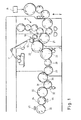
- FIG. 1 a Filteransetzmaschine is shown in fragmentary form in a front view, wherein the Filteransetzmaschine via a drum assembly T for supplying tobacco sticks from a schematically drawn cigarette rod machine P tobacco sticks of double-use length receives.
- a cigarette rod machine is known under the name "PROTOS" of the patent applicant.
- the tobacco rods are cut twice the length of use and spread longitudinally axially.
- the assembly drum 21 are transported over a further drum assembly M double-length filter plugs, which are inserted between two longitudinally spaced tobacco rods.
- a sequence of tobacco rod filter plug tobacco rod groups arranged transaxially behind one another is formed on the assembly drum 21.
- the assembled article groups are transferred from the assembly drum 21 to a conveyor drum 22.
- a glued and conveyed tipping paper strip 11 is cut in a tipping apparatus 10 on a cutting drum 12 by the knives of a knife drum 13 into tipping flakes.
- the cut compound leaflets are respectively attached to the article groups or tobacco rod filter plug tobacco rod groups handed over or attached to the conveyor drum 22.
- the article groups are further transported to a subsequent rolling drum 26 and a rolling device 27 by which the bonding sheets are completely wrapped around the tobacco rod filter plug tobacco rod groups.
- the rolling device 27 consists in one embodiment of a web wheel, a rolling hand with a rolling surface and the output side of a rolling roller, wherein the rolling surface and the rolling drum 26 form a rolling channel, are wrapped in the article groups with the connecting blades, with double-length filter cigarettes are formed.
- the double-length filter cigarettes are subsequently transferred to a conveyor drum 28 and further below to a further conveyor drum 29 and provided for the further processing process on a filter attachment machine.
- the double-length filter cigarettes are conveyed via a conveyor drum 30 to a cutting drum 31, on which a cutting blade 32 is arranged, which produces from the double-length filter cigarettes by a central separating cut filter cigarettes simple use length.
- the filter cigarettes are then transferred from the cutting drum 31 to a spreading drum 33.
- the pairs of filter cigarettes are spaced longitudinally from one another and then transferred to a first test drum 34.
- a first test element 44 is arranged, which the filter cigarettes a first
- Testing e.g. a bedside examination, undergoes.
- the manufactured filter cigarettes are subjected to an optical test on the first test device 44 designed as a test device.
- the cigarettes are transferred from the test drum 34 to a subsequent second test drum 35, to which a second test device 45 designed as a test device is arranged in order to subject the cigarettes to further quality tests, in particular a further optical test.
- Fig. 2 schematically shows a cross section through a drum assembly having a first conveyor drum 110 and a second conveyor drum 120, for example, part of a schematically designated Filteransetzmaschine F (see. Fig. 1 ) are.
- the conveyor drum 110 as conveying article 115 conveyor drum and the conveyor drum 120 as article 115 receiving conveyor drum is shown so that between the conveyor drum 110 and the conveyor drum 120 in a transfer area 130, the rod-shaped article 115 from the donating conveyor drum 110 to the receiving Conveying drum 120 are passed.
- the conveyor drum 110 has a drum body 112, which has receiving troughs 114 at regular intervals in the circumferential direction, in which the rod-shaped articles 115 such as filter rods or cigarettes or filter cigarettes are received.
- the receiving troughs 114 have, in cross-section, a trough contour that complements the shape of the curve or the circumference or the circular cross-sectional shape of the rod-shaped articles 115 is adjusted.
- the drum body 114 further has the receiving troughs 114 associated with suction bores 113 which are acted upon by suction, so that the rod-shaped articles 115 rest in the receiving troughs 114 of the conveyor drum 110 and are held.
- a control body 111 is arranged, which is surrounded by the rotating or rotationally driven drum body 112.
- the suction bores 113 of the drum body 112 in the conveying region for conveying the rod-shaped articles 115 are subjected to negative pressure until their transfer, so that the rod-shaped articles 115 are held in the receiving troughs 114.
- the suction holes 113 of the first conveyor drum 110 are or are vented, i. that no negative pressure or corresponding suction air is applied to the Saugluftbohritch 113 to the unoccupied receiving troughs 114.
- the rod-shaped articles 115 are arranged in the receiving cavities and conveyed to the transfer region 130 from a conveying drum arranged upstream in the conveying direction.
- the article 115 receiving second conveyor drum 120 has an outer drum body 122 which is provided at regular intervals with receiving troughs 124 in the circumferential direction.
- radially arranged suction bores 123 for the receiving cavities 124 are also formed in the drum body 122.
- a control body 121 is also disposed inside the conveyor drum 120.
- the drum body 122 is rotationally driven about the rotation axis R120 of the conveyor drum 120.
- the receiving cavities 124 of the drum body 122 are adapted to the geometric dimensions or the curvature of the rod-shaped articles 115 to be transported, wherein in particular the receiving cavities 124 are formed complementary to the circular average contour of the rod-shaped articles 115.
- the dispensing receiving trough 114 and the receiving receiving trough 124 are arranged in the transfer area 130 such that the, in particular maximum, distance between trough bottom of the issuing receiving trough 114 and the receiving receiving trough 124 is equal or smaller as the diameter of the round-shaped and circular-shaped article 115 is.
- the distance in the transfer region 130 to the transfer time between the trough bottom of the receiving trough 114 and the trough bottom of the receiving trough 124 is between 0.1 mm to 0.3 mm smaller than the circular diameter of the rod-shaped articles 115.
- the illustrated inventive principle of the transfer of rod-shaped articles is applicable in a corresponding manner for the transfer of articles between conveyor drums both with rigid and with moving receiving troughs for the rod-shaped article.
- Fig. 3a to 3c schematically the transfer of rod-shaped articles 115 from the first conveyor drum 110 to the adjacent second conveyor drum 120 in subsequent process steps on the filter attachment F shown.
- a Achsstichterrorism AS is formed between the center axes or the axes of rotation R110 and R120 of the two conveyor drums 110, 120.
- the Achsstichterrorism AS is determined by the distance between the center axes of the two adjacent conveyor drums 110, 120, which simultaneously form the axes of rotation R110 and R120 of the two conveyor drums 110, 120 respectively.
- the conveyor drum 110 has a radius B110 which is determined by the distance between the center axis or the rotation axis R110 and the trough bottom of the receiving trough 114 of the conveyor drum 110.
- the article-receiving conveyor drum 120 has a radius B120, which is determined by the distance between the center axis or the rotation axis R120 and the (lowest) trough bottom of the receiving trough 124 of the conveyor drum 120th
- the rod-shaped article 115 is conveyed by the conveying drum 110 into the transfer region 130, so that the rod-shaped article 115, which is held in the receiving trough 114 of the conveying drum, is introduced into the receiving trough 124 of the article-receiving conveying drum 120 and by abutment in the trough Saugluftbohrept the receiving trough 124 closes.
- the two conveyor drums 110, 120 With simultaneous rotation of the two conveyor drums 110, 120 and when forming a positive connection with the receiving troughs 114, 124 of the two conveyor drums 110, 120 of the article 115 to be transferred in the process step according to Fig.
- second conveyor drum 120 After the transfer of the rod-shaped article 115 according to Fig. 3c to the adjacent, second conveyor drum 120 is negative pressure in the suction holes of the receiving trough 124, while negative pressure at the suction holes of the receiving trough 114 is turned off. Characterized in that after the transfer of the rod-shaped article (see. Fig. 3b ) the distance between the trough bottom of the article-issuing receiving trough 114 and the article receiving receiving trough 124 is increased, the rod-shaped article 115 takes its circular cross-section again.
- Fig. 4a, 4b are enlarged sections of the transfer area 130 according to the in Fig. 3b shown process step shown schematically.
- the diameter d of the dashed, circular shaped rod-shaped article 115 is drawn, wherein the distance between the trough bottom of the two receiving wells 114, 124 is smaller than the diameter of the circular cross-section shaped article 115.
- the axial stitching AS is smaller than that Sum of the radius B110, the radius B120 and the diameter d of the rod-shaped article 115.
- FIG. 4b From the enlarged view in Fig. 4b also shows that the outer edge regions of the receiving troughs 114, 124 outside the (deepest) trough base have rounded edge regions as a trough shoulder. This results in a continuous trough contour of the receiving troughs 114 and 124, respectively, by the trough shoulders formed on both sides of the trough base.
Abstract
Description
Die Erfindung betrifft ein Verfahren zum Fördern von stabförmigen Artikeln der Tabak verarbeitenden Industrie, insbesondere Filterstäbe oder Zigaretten oder Filterstabgruppen oder hieraus zusammengestellten Artikelgruppen, wobei die stabförmigen Artikel in queraxialer Richtung in Aufnahmemulden von, insbesondere rotierend angetriebenen, Trommelkörpern von Fördertrommeln gefördert werden.The invention relates to a method for conveying rod-shaped articles of the tobacco-processing industry, in particular filter rods or cigarettes or filter rod groups or article groups composed thereof, wherein the rod-shaped articles are conveyed in transverse axial direction in receiving troughs of, in particular rotationally driven, drum bodies of conveyor drums.
Ferner betrifft die Erfindung eine Trommelmaschine der Tabak verarbeitenden Industrie, insbesondere Filteransetzmaschine, mit mehreren Fördertrommeln zum queraxialen Fördern von stabförmigen Artikeln der Tabak verarbeitenden Industrie, wobei die Fördertrommeln jeweils in Umfangsrichtung mit Aufnahmemulden zum Aufnehmen von stabförmigen Artikeln versehen sind.Furthermore, the invention relates to a drum machine of the tobacco processing industry, in particular Filteransetzmaschine, with several conveyor drums for Queraxialen conveyance of rod-shaped articles of the tobacco processing industry, the conveyor drums are each provided in the circumferential direction with receiving troughs for receiving rod-shaped articles.
Unter stabförmigen Artikeln der Tabak verarbeitenden Industrie werden im vorliegenden Zusammenhang solche Gegenstände verstanden, die in einlagiger Reihe mittels Saugluft auf Förderern, wie bspw. auf Fördertrommeln in Zigarettenherstellungsmaschinen, gehalten und von diesen gefördert werden. Solche Artikel sind Filterzigaretten, Zigarren, Zigarillos, Filterstäbe oder Filterstabgruppen usw. Wenn im Folgenden der Einfachheit halber nur noch von Zigaretten oder Filterstäben gesprochen wird, so gilt das Gesagte ganz entsprechend auch für andere zu fördernde stabförmige Artikel der vorgenannten Art.Under rod-shaped articles of the tobacco processing industry are understood in the present context, such articles that are held in single-ply row by suction on conveyors, such as. On conveyor drums in cigarette manufacturing machines, and promoted by these. Such articles are filter cigarettes, cigars, cigarillos, filter rods or filter rod groups, etc. If, for the sake of simplicity, only cigarettes or filter rods are mentioned below, then what has been said also applies correspondingly to other rod-shaped articles of the aforementioned type to be conveyed.
In einer Zigarettenherstellungsmaschine werden Zigaretten in einlagiger Reihe quer zu ihrer Achsrichtung auf Fördertrommeln, bei denen es sich in erster Linie um Trommeln von Zigarettenherstellungsmaschinen bzw. von Filteransetzmaschinen handelt, mit Saugluft gehalten. Hierzu weisen die Fördertrommeln in ihrer Umfangsfläche Saugluftöffnungen auf, die mit einer Unterdruckquelle in Verbindung stehen. Die Übergabe von Zigaretten von einem ersten Förderer zum nächsten Förderer erfolgt in der Regel dadurch, dass im jeweiligen abgebenden, ersten Förderer die Halteluft im Übergabebereich unterbrochen wird, während sie beim jeweils aufnehmenden, zweiten Förderer eingeschaltet wird. Zur Unterbrechung der Halteluft in dem den Übergabebereich bildenden Umfangsabschnitt des ersten Förderers sind in seinem Inneren feststehende Steuersegmente angeordnet, welche die Saugluftöffnungen des Förderers in diesem Abschnitt abdecken und dadurch vom Unterdruck trennen.In a cigarette making machine, cigarettes in a single ply row are held with suction air transversely to their axial direction on conveyor drums, which are primarily drums of cigarette making machines or filter tying machines. For this purpose, the conveyor drums have in their peripheral surface suction air openings which are in communication with a vacuum source. The transfer of cigarettes from a first conveyor to the next conveyor usually takes place in that in the respective dispensing, first conveyor, the holding air is interrupted in the transfer area, while it is turned on each receiving, second conveyor. For interrupting the holding air in the transfer region forming peripheral portion of the first conveyor fixed control segments are arranged in its interior, which cover the Saugluftöffnungen the conveyor in this section and thereby separate from the negative pressure.
In der Patentschrift
Weiterhin ist in
In der Patentschrift
Ausgehend von diesem Stand der Technik ist es Aufgabe der vorliegenden Erfindung, beim Transport von stabförmigen Artikeln auf Fördertrommeln die Geräuschemission sowie den Verbrauch an Luft zu reduzieren.Based on this prior art, it is an object of the present invention to reduce the noise emission and the consumption of air during the transport of rod-shaped articles on conveyor drums.
Gelöst wird diese Aufgabe durch ein Verfahren zum Fördern von stabförmigen Artikeln der Tabak verarbeitenden Industrie, insbesondere Filterstäbe oder Zigaretten oder Filterstabgruppen oder hieraus zusammengestellten Artikelgruppen, wobei die stabförmigen Artikel in queraxialer Richtung in Aufnahmemulden von, insbesondere rotierend angetriebenen, Trommelkörpern von Fördertrommeln gefördert werden, wobei die stabförmigen Artikel einzeln aus den abgebenden Aufnahmemulden der ersten Fördertrommel in einem Übergabebereich an die aufnehmenden Aufnahmemulden der zweiten Fördertrommel übergeben werden, wobei die Artikel auf der ersten Fördertrommel mittels Unterdruck in den Aufnahmemulden gehalten und zum Übergabebereich gefördert werden, im Übergabebereich zwischen der ersten Fördertrommel und der zweiten Fördertrommel und während der oder bei der Übergabe an jeweils eine Aufnahmemulde des Trommelkörpers der zweiten Fördertrommel die Artikel jeweils unter Ausbildung eines Formschlusses mit der, vorzugsweise am jeweiligen zu übergebenden Artikel anliegenden, Kontur der abgebenden Aufnahmemulde der ersten Fördertrommel und unter, vorzugsweise gleichzeitiger Ausbildung eines Formschlusses mit der, vorzugsweise am jeweiligen zu übergebenden Artikel anliegenden, Kontur der aufnehmenden Aufnahmemulde der zweiten Fördertrommel übergeben werden, wobei mit der Ausbildung des beidseitigen Formschlusses der einzelnen Artikel jeweils der Halteunterdruck an der abgebenden Aufnahmemulde der ersten Fördertrommel abgeschaltet ist und gleichzeitig der stabförmige Artikel mit Halteunterdruck an der aufnehmenden Aufnahmemulde der zweiten Fördertrommel beaufschlagt wird.This object is achieved by a method for promoting rod-shaped articles of the tobacco-processing industry, in particular filter rods or cigarettes or filter rod groups or grouped therefrom article groups, the rod-shaped articles are conveyed in transverse axial direction in receiving troughs of, in particular rotationally driven drum bodies of conveyor drums, the rod-shaped articles individually from the donating receiving troughs of the first Conveying drum are transferred in a transfer area to the receiving receiving wells of the second conveyor drum, wherein the articles are held on the first conveyor drum by means of negative pressure in the receiving troughs and conveyed to the transfer area, in the transfer area between the first conveyor drum and the second conveyor drum and during or during the transfer in each case a receiving trough of the drum body of the second conveyor drum, the articles each with the formation of a positive connection with the, preferably at the respective übergeb end of the article, contour of the donor receiving trough of the first conveyor drum and under, preferably simultaneous formation of a positive connection with the, preferably applied to each article to be submitted, contour of the receiving receiving trough of the second conveyor drum are passed, with the formation of the two-sided positive connection of the individual items each of the holding vacuum is switched off at the donor receiving trough of the first conveyor drum and at the same time the rod-shaped article is subjected to holding negative pressure at the receiving receiving trough of the second conveyor drum.
Die Erfindung beruht auf dem Gedanken, dass die stabförmigen Artikel jeweils von einer abgebenden Aufnahmemulde einer ersten Fördertrommel in eine aufnehmende Aufnahmemulde einer zweiten Fördertrommel übergeben werden, wobei das Vakuum bzw. die Saugluft an der aufnehmenden Aufnahmemulde der zweiten Fördertrommel erst mit der Übergabe des Artikels wirksam wird, wobei die Belüftung der abgebenden Aufnahmemulde ebenfalls erst im Übergabebereich bzw. im Übergabepunkt eingeschaltet wird. Hierbei werden gegenüber dem Stand der Technik die Filterstäbe, Filterzigaretten oder dergleichen zwischen den Fördertrommeln derart übergeben, dass die Filterstäbe keinen Sprung zwischen den Aufnahmemulden, insbesondere zwischen dem Muldengrund der abgebenden Aufnahmemulde und der aufnehmenden Aufnahmemulde, ausführen.The invention is based on the idea that the rod-shaped articles are each transferred from a donating receiving trough of a first conveyor drum in a receiving receiving trough a second conveyor drum, wherein the vacuum or the suction air at the receiving receiving trough of the second conveyor drum only with the delivery of the article is effective, the ventilation of the donor receiving trough is also switched on only in the transfer area or in the transfer point. Here, compared to the prior art, the filter rods, filter cigarettes or the like passed between the conveyor drums so that the filter rods do not jump between the receiving wells, in particular between the trough bottom of the donor receiving trough and the receiving receiving trough perform.
Gemäß dem Stand der Technik werden bislang bei der Übergabe von stabförmigen Artikeln von einer abgebenden Aufnahmemulde auf eine nachfolgende aufnehmende Aufnahmemulde einer zweiten Fördertrommel die Artikelstäbe derart übergeben, dass sie einen (kleinen) Bewegungssprung zwischen dem Muldengrund der abgebenden Aufnahmemulde und dem Muldengrund der aufnehmenden Aufnahmemulde ausführen.According to the prior art, in the transfer of rod-shaped articles from a donor receiving trough to a subsequent receiving trough of a second conveyor drum, the article rods have so far been handed over so that they perform a (small) movement jump between the trough bottom of the donor trough and the trough bottom of the receiving trough ,
Hierbei ist das Haltevakuum an den Aufnahmemulden zum Halten der stabförmigen Artikel während ihrer Förderung auf den Trommelkörpern so ausgelegt, dass bei der abgebenden Fördertrommel vor Erreichen der Übergabeposition an den Saugbohrungen der abgebenden Aufnahmemulde Belüftungsluft, d.h. kein Unterdruck, anliegt und vor Erreichen der Übergabeposition die Aufnahmemulde auf der zweiten Fördertrommel mit Saugluft beaufschlagt ist, d.h. ein Haltevakuum an den (offenen, bzw. nicht belegten) Aufnahmemulden der zweiten Fördertrommel anliegt. Somit wird gemäß dem Stand der Technik eine Luftströmung im Übergabebereich an den Aufnahmemulden erzeugt, wobei durch die springende Bewegung der Artikel bei der Übergabe der stabförmigen Artikel Plopp-Geräusche entstehen.Here, the holding vacuum on the receiving troughs for holding the rod-shaped article during its promotion on the drum bodies is designed so that at the donating conveyor drum before reaching the transfer position on the suction holes of the donor receiving trough ventilation air, ie no negative pressure, and before reaching the transfer position, the receiving trough Suction air is applied to the second conveyor drum, ie, a holding vacuum is applied to the (open or unoccupied) receiving troughs of the second conveyor drum. Thus, according to the prior art, an air flow is generated in the transfer area at the receiving troughs, resulting in the jumping movement of the article in the transfer of the rod-shaped article popping noise.
Demgegenüber ist gemäß der Erfindung vorgesehen, dass die zu übergebenden Artikelstäbe oder dergleichen im Übergabebereich keine springende Bewegung zwischen dem Muldengrund der abgebenden Aufnahmemulde und dem Muldengrund der aufnehmenden Aufnahmemulde ausführen, wobei die Ansaugbohrung oder dergleichen an der Aufnahmemulde der zweiten Fördertrommel beim Einbringen bis zur Übergabe des stabförmigen Artikels in die aufnehmende Mulde belüftet sind und nach Einbringen des Artikels in die aufnehmende Aufnahmemulde der zweiten Fördertrommel unter Ausbildung eines Formschlusses zwischen dem im Querschnitt rundgeformten Artikel und der formkomplementär ausgebildeten Aufnahmemulde abgedichtet wird, bevor das Haltevakuum zum Halten des Artikels in der Aufnahmemulde der zweiten Fördertrommel zugeschaltet wird. Hierdurch wird die Ausbildung einer Luftströmung im Übergabebereich zwischen den Fördertrommeln vermieden. Somit wird die Geräuschentwicklung durch das vermiedene Springen der Artikelstäbe und das erfindungsgemäße Schalten der Saugluftunterdrücke an den Aufnahmemulden der Fördertrommeln herabgesetzt. Insbesondere wird das Haltevakuum bzw. Unterdruck zum Halten des Artikels in der Aufnahmemulde der zweiten Fördertrommel erst nach Verschließen der Saugluftbohrungen der Artikel aufnehmenden Aufnahmemulde der zweiten Fördertrommel durch den in der Aufnahmemulde angeordneten Artikel zugeschaltet.In contrast, it is provided according to the invention that the transferable article rods or the like in the transfer area no jumping movement between the trough of the donor receiving trough and the trough base of receiving receiving trough run, the suction hole or the like on the receiving trough of the second conveyor drum during introduction to the transfer of the rod-shaped article are ventilated into the receiving trough and sealed after insertion of the article into the receiving receiving recess of the second conveyor drum to form a positive connection between the cross-sectional shaped article and the formkomplementär trained receiving trough before the holding vacuum for holding the article in the receiving trough of the second Conveyor drum is switched on. As a result, the formation of an air flow in the transfer area between the conveyor drums is avoided. Thus, the noise is reduced by the avoided jumping of the article rods and switching the Saugluftunterdrücke according to the invention at the receiving troughs of the conveyor drums. In particular, the holding vacuum or vacuum for holding the article in the receiving trough of the second conveyor drum is switched on only after closing the Saugluftbohrungen the article receiving receiving trough of the second conveyor drum through the arranged in the receiving trough article.
Aufgrund des gleichzeitigen Formschlusses der zu übergebenden Artikel im Übergabezeitpunkt und im Übergabebereich mit der rundgeformten Kontur der abgebenden Aufnahmemulde der ersten Fördertrommel und mit der Kontur der aufnehmenden Aufnahmemulde der zweiten Fördertrommel wird erreicht, dass die stabförmigen Artikel keinen Bewegungssprung in radialer Richtung bezogen auf die Rotationsachsen der ersten und/oder zweiten Fördertrommel ausführen.Due to the simultaneous positive fit of the article to be submitted at the time of transfer and in the transfer area with the rounded contour of the donor receiving trough of the first conveyor drum and with the contour of the receiving receiving trough of the second conveyor drum is achieved that the rod-shaped article no movement jump in the radial direction relative to the axes of rotation perform first and / or second conveyor drum.
Im Rahmen der Erfindung wird unter einem Formschluss ein flächenhaftes Anliegen des stabförmigen Artikels zwischen der aufnehmenden Aufnahmemulde und der abgebenden Aufnahmemulde verstanden, so dass die Saugbohrungen oder Haltebohrungen der Aufnahmemulden verschlossen sind.In the context of the invention is understood by a positive fit a planar concerns of the rod-shaped article between the receiving receiving trough and the donor receiving trough, so that the suction holes or retaining holes of the receiving troughs are closed.
Darüber hinaus ist es in einer Weiterbildung des Verfahrens vorteilhaft, dass bei Ausbildung des beidseitigen Formschlusses des zu übergebenden Artikels mit der Kontur der abgebenden Aufnahmemulde der ersten Fördertrommel und mit der Kontur der aufnehmenden Aufnahmemulde der zweiten Fördertrommel im Übergabebereich der Abstand zwischen dem Muldengrund der abgebenden Aufnahmemulde der ersten Fördertrommel und dem Muldengrund der aufnehmenden Aufnahmemulde der zweiten Fördertrommel gleich oder kleiner, insbesondere um 0,1 mm bis 0,3 mm kleiner, als der Durchmesser des zu übergebenden Artikels ist.In addition, it is advantageous in a development of the method that when forming the two-sided positive connection of the article to be submitted with the contour of the donor receiving trough of the first conveyor drum and the contour of the receiving receiving trough of the second conveyor drum in the transfer area, the distance between the trough bottom of the donor receiving trough the first conveyor drum and the trough base of the receiving receiving trough of the second conveyor drum is equal to or smaller, in particular by 0.1 mm to 0.3 mm smaller than the diameter of the article to be transferred.
Außerdem ist es bei der Weiterbildung des Verfahrens bevorzugt, dass die zu übergebenden Artikel jeweils im Übergabebereich bewegungsimpulsfrei von der abgebenden Aufnahmemulde der ersten Fördertrommel zur aufnehmenden Aufnahmemulde der zweiten Fördertrommel übergeben werden. Hierbei werden die zu übergebenden stabförmigen Artikel bei der Übergabe nicht mit einem zusätzlichen Bewegungsimpuls in radialer Richtung bezogen auf die Rotationsachsen der Fördertrommeln beaufschlagt, um von der abgebenden Aufnahmemulde zur aufnehmenden Aufnahmemulde bewegt zu werden.In addition, in the development of the method, it is preferred that the articles to be transferred are each transferred in the transfer region from the donating receiving trough of the first conveyor drum to the receiving trough of the second conveyor drum without movement impulses. In this case, the rod-shaped articles to be transferred are not subjected to an additional movement pulse in the radial direction relative to the axes of rotation of the conveyor drums during transfer, in order to be moved from the issuing receiving trough to the receiving trough.
Dazu ist es außerdem in einer Ausgestaltung des Verfahren bevorzugt, dass die zu übergebenden Artikel jeweils im Übergabebereich wenigstens eine oder mehrere Ansaugbohrungen der aufnehmenden Aufnahmemulde der zweiten Fördertrommel mit Ausbildung des Formschlusses mit der aufnehmenden Aufnahmemulde verschließen, wobei insbesondere die zu übergebenden Artikel jeweils mit Unterdruck an der abgebenden Aufnahmemulde der ersten Fördertrommel beaufschlagt sind. Hierbei ist weiterhin vorgesehen, dass nach Verschließen oder bei Verschließen der Ansaugbohrungen der jeweiligen aufnehmenden Aufnahmemulden der Unterdruck an der oder den Ansaugbohrungen der abgebenden Aufnahmemulde der ersten Fördertrommel abgeschaltet wird oder ist. Dies erfolgt insbesondere vor sowie bei Ausbildung des gleichzeitigen Formschlusses der zu übergebenden Artikel mit der abgebenden Aufnahmemulde und mit der aufnehmenden Aufnahmemulde der benachbarten Fördertrommeln.For this purpose, it is also preferred in one embodiment of the method that the articles to be transferred each in the transfer area at least one or more suction holes of the receiving Include receiving trough the second conveyor drum with formation of the positive connection with the receiving receiving trough, wherein in particular the articles to be transferred are each subjected to negative pressure at the donating receiving trough of the first conveyor drum. It is further provided that after closing or closing the suction holes of the respective receiving receiving troughs, the negative pressure at the or the suction holes of the donor receiving trough of the first conveyor drum is turned off or is. This is done in particular before and during formation of the simultaneous positive connection of the articles to be handed over with the donating receiving trough and with the receiving receiving trough of the adjacent conveyor drums.
Durch das Einbringen der Artikelstäbe in die aufnehmenden Aufnahmemulden wird oder werden die Ansaugbohrungen dieser aufnehmenden Aufnahmemulde verschlossen und abgedichtet, bevor das Haltevakuum an den Ansaugbohrungen der aufnehmenden Aufnahmemulde zugeschaltet wird. Gleichzeitig oder kurz danach wird bei Beaufschlagung der Ansaugbohrungen der aufnehmenden Aufnahmemulde mit Saugluft die Ansaugbohrung oder Ansaugbohrungen der gegenüberliegenden abgebenden Aufnahmemulde der ersten Fördertrommel entsprechend belüftet, wodurch die Belüftung der abgebenden Fördertrommel erst zu diesem Zeitpunkt eingeschaltet wird und kein Haltevakuum an der abgebenden Aufnahmemulde anliegt. Insbesondere wird das Haltevakuum bzw. die Saugluft an den Aufnahmemulden der zweiten Fördertrommel erst mit der Übergabe, d.h. zum Zeitpunkt zugeschaltet oder eingeschaltet, zu dem die Längsmittenachse der jeweiligen stabförmigen Artikel auf der Verbindungslinie der beiden Fördertrommelmittelpunkte bzw. den Rotationsachsen der Fördertrommeln angeordnet ist.By introducing the article rods into the receiving receiving wells, the suction holes of this receiving receiving well are sealed and sealed before the holding vacuum is applied to the suction wells of the receiving receiving well. At the same time or shortly thereafter, when the suction holes of the receiving receiving trough with suction air is applied, the suction bore or suction holes of the opposite donor receiving trough of the first conveyor drum is ventilated accordingly, whereby the ventilation of the donating conveyor drum is turned on only at this time and no holding vacuum is applied to the donating receiving trough. In particular, the holding vacuum or the suction air at the receiving troughs of the second conveyor drum is switched on or switched on at the time when the longitudinal center axis of the respective rod-shaped articles is arranged on the connecting line of the two conveyor drum centers or the axes of rotation of the conveyor drums.
Ferner wird die Aufgabe gelöst durch eine Trommelmaschine der Tabak verarbeitenden Industrie, insbesondere Filteransetzmaschine, mit mehreren Fördertrommeln zum queraxialen Fördern von stabförmigen Artikeln der Tabak verarbeitenden Industrie, wobei die Fördertrommeln jeweils in Umfangsrichtung mit Aufnahmemulden zum Aufnehmen von stabförmigen Artikeln versehen sind, die dadurch weitergebildet wird, dass jeweils zwei benachbarte Fördertrommeln derart angeordnet sind, dass das Achsstichmaß zwischen den Mittenachsen der Fördertrommeln gleich oder kleiner ist als die Summe aus dem Radius einer ersten Fördertrommel zwischen der Mittenachse der ersten Fördertrommel und dem Muldengrund der, vorzugsweise im Übergabebereich zwischen den benachbarten Fördertrommeln befindlichen, Aufnahmemulden der ersten Fördertrommel und aus dem Radius einer zweiten benachbarten Fördertrommel zwischen der Mittenachse der zweiten Fördertrommel und dem Muldengrund der, vorzugsweise im Übergabebereich zwischen den benachbarten Fördertrommeln befindlichen, Aufnahmemulden der zweiten Fördertrommel und aus dem, vorzugsweise kleinsten, Durchmesser der zu fördernden stabförmigen Artikel.Furthermore, the object is achieved by a drum machine of the tobacco-processing industry, in particular filter attachment machine, with several conveyor drums for Queraxialen conveying rod-shaped articles of the tobacco industry, wherein the conveyor drums are each provided in the circumferential direction with receiving troughs for receiving rod-shaped articles, which is further developed in that in each case two adjacent conveyor drums are arranged such that the axial stitch dimension between the center axes of the conveyor drums is equal to or smaller than the sum of the radius of a first conveyor drum between the center axis of the first conveyor drum and the trough base, preferably located in the transfer area between the adjacent conveyor drums , Receiving wells of the first conveyor drum and from the radius of a second adjacent conveyor drum between the center axis of the second conveyor drum and the trough base, preferably in Übergabeber eich located between the adjacent conveyor drums, receiving wells of the second conveyor drum and from the, preferably smallest, diameter of the promotional rod-shaped article.
Im Rahmen der Erfindung wird unter einem Achsstichmaß von zwei benachbarten Fördertrommeln der Abstand zwischen den Mittenachsen von zwei benachbarten Fördertrommeln, zwischen denen stabförmige Artikel übergeben werden, verstanden. Insbesondere sind die Mittenachsen der jeweils benachbarten Fördertrommeln als Rotationsachsen der Fördertrommeln ausgebildet.In the context of the invention, the distance between the center axes of two adjacent conveyor drums, between which rod-shaped articles are transferred, is understood by an axial stitch dimension of two adjacent conveyor drums. In particular, the center axes of the respective adjacent conveyor drums are formed as axes of rotation of the conveyor drums.
Gemäß der Erfindung ist dabei vorgesehen, dass im Übergabezeitpunkt bzw. im Übergabebereich von stabförmigen Artikeln von einer Fördertrommel an die nachfolgende benachbarte Fördertrommel der Abstand zwischen den Mittenachsen bzw. Rotationsachsen der benachbarten Fördertrommeln gleich oder kleiner ist als der Abstand zwischen dem tiefsten Punkt des Muldengrundes der abgebenden Aufnahmemulde der ersten Fördertrommel zur Rotationsachse, in der im Zusammenhang mit der vorliegenden Erfindung als Radius der ersten Fördertrommel zwischen der Mittenachse der ersten Fördertrommel und dem Muldengrund der Aufnahmemulde bezeichnet wird, und dem Radius, d.h. dem Abstand zwischen dem (tiefsten) Muldengrund der aufnehmenden Aufnahmemulde der zweiten Fördertrommel an seiner tiefsten Stelle und der Mittenachse bzw. der Rotationsachse der zweiten Fördertrommel sowie dem Durchmesser der zu fördernden stabförmigen Artikel. Hierbei ist im Übergabezeitpunkt bzw. im Übergabebereich der Abstand zwischen dem Muldengrund der abgebenden Aufnahmemulde und dem Muldengrund der aufnehmenden Aufnahmemulde der zweiten Fördertrommel gleich dem oder kleiner als der Durchmesser des zu übergebenden stabförmigen Artikels bzw. der an der Trommelmaschine hergestellten stabförmigen Artikel. In einer Ausgestaltung entspricht der Abstand vom Muldengrund der abgebenden Aufnahmemulde und der aufnehmenden Aufnahmemulde dem Durchmesser des zu übergebenden oder übergebenen stabförmigen Artikels.According to the invention, provision is made for the distance between the center axes or rotational axes of the adjacent conveyor drums to be equal to or smaller than the distance at the time of transfer or in the transfer area of rod-shaped articles from one conveyor drum to the following adjacent conveyor drum between the lowest point of the trough bottom of the donor receiving trough of the first conveyor drum to the axis of rotation, in the context of the present invention as the radius of the first conveyor drum between the center axis of the first conveyor drum and the trough base of the receiving trough, and the radius, ie the distance between the (lowest) trough base of the receiving receiving trough of the second conveyor drum at its lowest point and the center axis or the axis of rotation of the second conveyor drum and the diameter of the rod-shaped article to be conveyed. Here, in the transfer time or in the transfer area, the distance between the trough bottom of the donor receiving trough and the trough base of the receiving receiving trough of the second conveyor drum is equal to or smaller than the diameter of the rod-shaped article to be transferred or the rod-shaped article produced on the drum machine. In one embodiment, the distance from the trough bottom of the donor receiving trough and the receiving receiving well corresponds to the diameter of the rod-shaped article to be transferred or transferred.
Durch eine derartige Anordnung der Fördertrommel wird bei einer Trommelmaschine, insbesondere einer Filteransetzmaschine, erreicht, dass die Geräuschentwicklung herabgesetzt ist, wodurch ein ruhigerer Betrieb der Trommelmaschine zur Herstellung oder zur Förderung von stabförmigen Artikeln möglich ist.Such an arrangement of the conveyor drum is achieved in a drum machine, in particular a Filteransetzmaschine, that the noise is reduced, whereby a quieter operation of the drum machine for the production or promotion of rod-shaped articles is possible.
Insbesondere zeichnet sich eine Weiterbildung der Trommelmaschine dadurch aus, dass ausschließlich alle Fördertrommeln der Trommelmaschine derart angeordnet sind, dass das jeweilige Achsstichmaß zwischen den Mittenachsen zweier benachbarter Fördertrommeln gleich oder kleiner ist als die Summe aus dem Radius der ersten Fördertrommel zwischen der Mittenachse der ersten Fördertrommel und dem Muldengrund der, vorzugsweise im Übergabebereich zwischen den benachbarten Fördertrommeln befindlichen, Aufnahmemulden der ersten Fördertrommel und aus dem Radius der benachbarten zweiten Fördertrommel zwischen der Mittenachse der zweiten Fördertrommel und dem Muldengrund der, vorzugsweise im Übergabebereich zwischen den benachbarten Fördertrommeln befindlichen, Aufnahmemulden der zweiten Fördertrommel und aus dem Durchmesser der zu fördernden stabförmigen Artikel an der Trommelmaschine.In particular, a development of the drum machine is characterized in that only all conveyor drums of the drum machine are arranged such that the respective Achsstichmaß between the center axes of two adjacent conveyor drums is equal to or smaller than the sum of the radius of the first conveyor drum between the center axis of the first conveyor drum and the trough bottom of, preferably located in the transfer region between the adjacent conveyor drums, receiving troughs of the first conveyor drum and from the radius of the adjacent second conveyor drum between the center axis of the second conveyor drum and the trough bottom, preferably located in the transfer area between the adjacent conveyor drums, receiving troughs of the second conveyor drum and from the diameter of the rod-shaped article to be conveyed on the drum machine.
Hierbei ist die Trommelmaschine der Tabak verarbeitenden Industrie insbesondere ausgelegt zur Herstellung von stabförmigen Artikeln mit einem festgelegten Durchmesser, so dass an einer Filteransetzmaschine ausschließlich Filterzigaretten mit einem vorher festgelegten Durchmesser hergestellt werden. Insofern handelt es sich bei der Trommelmaschine um eine einformatige Trommelmaschine zur Herstellung von stabförmigen Artikeln. Vorzugsweise wird die Trommelmaschine gemäß dem beschriebenen Verfahren betrieben.Here, the drum machine of the tobacco processing industry is particularly designed for the production of rod-shaped articles with a fixed diameter, so that exclusively filter cigarettes are made with a predetermined diameter on a filter attachment machine. In this respect, the drum machine is a single-format drum machine for the production of rod-shaped articles. Preferably, the drum machine is operated according to the described method.
Darüber hinaus zeichnet sich eine bevorzugte Ausführungsform der Trommelmaschine dadurch aus, dass die Aufnahmemulden der Fördertrommeln im Randbereich der Aufnahmemulden und außerhalb des Muldengrundes der Aufnahmemulden in Bezug auf die queraxiale Förderrichtung der Fördertrommeln beidseits des Muldengrundes jeweils eine kontinuierliche, insbesondere abgerundete, Muldenschulter aufweisen.In addition, a preferred embodiment of the drum machine is characterized in that the receiving cavities of the conveyor drums in the edge region of the receiving troughs and outside of the trough bottom of the receiving troughs with respect to the transverse axial conveying direction of the conveyor drums on both sides of the trough base each have a continuous, in particular rounded, trough shoulder.
Dieses ist insbesondere bei einer Trommelmaschine vorgesehen, bei der das Achsstichmaß zwischen den Mittenachsen bzw. den Rotationsachsen von benachbarten Fördertrommeln kleiner ist als die Summe aus dem Radius zwischen der Mittenachse der ersten Fördertrommel und dem Muldengrund der Artikel abgebenden Aufnahmemulde der ersten Fördertrommel und dem Radius der benachbarten zweiten Fördertrommel zwischen der Mittenachse und dem Muldengrund der Artikel aufnehmenden Aufnahmemulde der zweiten Fördertrommel und dem Durchmesser des zu übergebenden stabförmigen Artikels.This is particularly provided in a drum machine in which the Achsstichmaß between the center axes and the axes of rotation of adjacent conveyor drums is smaller than the sum of the radius between the center axis of the first conveyor drum and the trough bottom of the article-releasing receiving trough of the first conveyor drum and the radius of the adjacent second conveyor drum between the central axis and the trough bottom of the article receiving receiving trough of the second conveyor drum and the diameter of the rod-shaped article to be transferred.
Weitere Merkmale der Erfindung werden aus der Beschreibung erfindungsgemäßer Ausführungsformen zusammen mit den Ansprüchen und der beigefügten Zeichnung ersichtlich. Erfindungsgemäße Ausführungsformen können einzelne Merkmale oder eine Kombination mehrerer Merkmale erfüllen.Further features of the invention will become apparent from the description of embodiments according to the invention together with the claims and the accompanying drawings. Embodiments of the invention may satisfy individual features or a combination of several features.
Die Erfindung wird nachstehend ohne Beschränkung des allgemeinen Erfindungsgedankens anhand eines Ausführungsbeispiel unter Bezugnahme auf die Zeichnungen beschrieben, wobei bezüglich aller im Text nicht näher erläuterten erfindungsgemäßen Einzelheiten ausdrücklich auf die Zeichnungen verwiesen wird. Es zeigen:
- Fig. 1
- schematisch eine Filteransetzmaschine gemäß dem Stand der Technik in einer Vorderansicht;
- Fig. 2
- schematisch im Ausschnitt einen Querschnitt durch eine Trommelanordnung mit zwei Fördertrommeln im Übergabebereich von stabförmigen Artikeln;
- Fig. 3a bis 3c
- schematisch die Übergabe eines stabförmigen Artikel zwischen zwei benachbarten Fördertrommeln und
- Fig. 4a, 4b
- schematisch jeweils vergrößerte Ausschnitte des Übergabebereichs zwischen den beiden Fördertrommeln (vgl.
Fig. 3a bis 3c ).
- Fig. 1
- schematically a filter attachment machine according to the prior art in a front view;
- Fig. 2
- schematically in section a cross section through a drum assembly with two conveyor drums in the transfer area of rod-shaped articles;
- Fig. 3a to 3c
- schematically the transfer of a rod-shaped article between two adjacent conveyor drums and
- Fig. 4a, 4b
- schematically each enlarged sections of the Transfer region between the two conveyor drums (see.
Fig. 3a to 3c ).
In den folgenden Figuren sind jeweils gleiche oder gleichartige Elemente bzw. entsprechende Teile mit denselben Bezugsziffern versehen, so dass von einer entsprechenden erneuten Vorstellung abgesehen wird.In the following figures, identical or similar elements or corresponding parts are provided with the same reference numerals, so that a corresponding renewed idea is dispensed with.
In
Auf ihrem Förderweg zu einer Zusammenstelltrommel 21 werden die Tabakstöcke doppelter Gebrauchslänge geschnitten und längsaxial gespreizt. Auf der Zusammenstelltrommel 21 werden über eine weitere Trommelanordnung M doppeltlange Filterstopfen transportiert, die jeweils zwischen zwei längsaxial beabstandete Tabakstöcke eingefügt werden. Hierdurch wird auf der Zusammenstelltrommel 21 eine Folge von queraxial hintereinander angeordneten TabakstockFilterstopfen-Tabakstock-Gruppen gebildet. Die zusammengestellten Artikelgruppen werden von der Zusammenstelltrommel 21 an eine Fördertrommel 22 übergeben.On their conveyor to a
Ein beleimter und geförderter Belagpapierstreifen 11 wird in einem Belagapparat 10 auf einer Schneidtrommel 12 von den Messern einer Messertrommel 13 in Belagblättchen bzw. Verbindungsblättchen geschnitten. Die geschnittenen Verbindungsblättchen werden jeweils an die Artikelgruppen bzw. Tabakstock-Filterstopfen-Tabakstock-Gruppen auf der Fördertrommel 22 übergeben bzw. angeheftet.A glued and conveyed
Nach dem Anheften der geschnittenen und der einzelnen Verbindungsblättchen an jeweils eine Artikelgruppe werden die Artikelgruppen weiter zu einer nachfolgenden Rolltrommel 26 und einer Rolleinrichtung 27 transportiert, mittels der die Verbindungsblättchen vollständig um die Tabakstock-Filterstopfen-TabakstockGruppen herumgewickelt werden. Die Rolleinrichtung 27 besteht in einer Ausgestaltung aus einem Stegrad, einer Rollhand mit einer Rollfläche und ausgangsseitig einer Rollwalze, wobei die Rollfläche und die Rolltrommel 26 einen Rollkanal bilden, in dem Artikelgruppen mit den Verbindungsblättchen umwickelt werden, womit doppeltlange Filterzigaretten gebildet werden.After adhering the cut and individual bonding sheets to one article group, the article groups are further transported to a subsequent rolling
Die doppeltlangen Filterzigaretten werden nachfolgend an eine Fördertrommel 28 und weiter nachfolgend an eine weitere Fördertrommel 29 übergeben und für den weiteren Bearbeitungsprozess an einer Filteransetzmaschine bereitgestellt.The double-length filter cigarettes are subsequently transferred to a
Von der Fördertrommel 29 werden die doppeltlangen Filterzigaretten über eine Fördertrommel 30 zu einer Schneidtrommel 31 gefördert, an der ein Schneidmesser 32 angeordnet ist, welches aus den doppeltlangen Filterzigaretten durch einen mittigen Trennschnitt Filterzigaretten einfacher Gebrauchslänge herstellt.From the
Die Filterzigaretten werden anschließend von der Schneidtrommel 31 an eine Spreiztrommel 33 übergeben. Auf der Spreiztrommel 33 werden die Filterzigarettenpaare längsaxial voneinander beabstandet und anschließend an eine erste Prüftrommel 34 übergeben. An der als Förderorgan ausgebildeten Prüftrommel 34 ist ein erstes Prüforgan 44 angeordnet, welches die Filterzigaretten einer erstenThe filter cigarettes are then transferred from the cutting
Prüfung, z.B. einer Kopfendenprüfung, unterzieht.Testing, e.g. a bedside examination, undergoes.
Im Rahmen der Erfindung ist es möglich, dass die hergestellten Filterzigaretten an dem ersten als Prüfeinrichtung ausgebildeten Prüforgan 44 einer optischen Prüfung unterzogen werden.In the context of the invention, it is possible that the manufactured filter cigarettes are subjected to an optical test on the
Anschließend werden die Zigaretten von der Prüftrommel 34 an eine nachfolgende zweite Prüftrommel 35 übergeben, an der ein zweites als Prüfeinrichtung ausgebildetes Prüforgan 45 angeordnet ist, um die Zigaretten weiteren Qualitätsprüfungen, insbesondere einer weiteren optischen Prüfung zu unterziehen.Subsequently, the cigarettes are transferred from the
Gemäß dem dargestellten Ausführungsbeispiel ist die Fördertrommel 110 als Artikel 115 abgebende Fördertrommel und die Fördertrommel 120 als Artikel 115 aufnehmende Fördertrommel dargestellt, so dass zwischen der Fördertrommel 110 und der Fördertrommel 120 in einem Übergabebereich 130 die stabförmigen Artikel 115 von der abgebenden Fördertrommel 110 an die aufnehmende Fördertrommel 120 übergeben werden.According to the illustrated embodiment, the
Die Fördertrommel 110 weist einen Trommelkörper 112 auf, der in regelmäßigen Abständen in Umfangsrichtung Aufnahmemulden 114 aufweist, in denen die stabförmigen Artikel 115 wie z.B. Filterstäbe oder Zigaretten oder Filterzigaretten aufgenommen werden. Die Aufnahmemulden 114 weisen im Querschnitt eine Muldenkontur auf, die an die Krümmung bzw. an den Umfang bzw. die kreisförmige Querschnittsform der stabförmigen Artikel 115 formkomplementär angepasst ist. Der Trommelkörper 114 weist ferner den Aufnahmemulden 114 zugeordnete Saugbohrungen 113 auf, die mit Saugluft beaufschlagt werden, so dass die stabförmigen Artikel 115 in den Aufnahmemulden 114 der Fördertrommel 110 anliegen und festgehalten werden.The
Im Inneren der Fördertrommel 110 ist ein Steuerkörper 111 angeordnet, der von dem umlaufenden bzw. rotierend angetriebenen Trommelkörper 112 umgeben ist. Durch den Steuerkörper 111 wird erreicht, dass die Saugbohrungen 113 des Trommelkörpers 112 im Förderbereich zum Fördern der stabförmigen Artikel 115 mit Unterdruck bis zu ihrer Übergabe beaufschlagt sind, so dass die stabförmigen Artikel 115 in den Aufnahmemulden 114 gehalten werden. Nach der Übergabe der stabförmigen Artikel 115 an die Artikel 115 aufnehmende Fördertrommel 120 sind oder werden die Saugbohrungen 113 der ersten Fördertrommel 110 belüftet, d.h. dass kein Unterdruck oder entsprechende Saugluft an den Saugluftbohrungen 113 an den nicht belegten Aufnahmemulden 114 anliegt.Inside the
Durch die Rotation des Trommelkörpers 112 um die Rotationsachse R110 werden nach Aufnahme der stabförmigen Artikel 115 von einer in Förderrichtung stromaufwärts angeordneten Fördertrommel die stabförmigen Artikel 115 in den Aufnahmemulden angeordnet und zum Übergabebereich 130 gefördert.As a result of the rotation of the
Die Artikel 115 aufnehmende zweite Fördertrommel 120 weist einen äußeren Trommelkörper 122 auf, der in regelmäßigen Abständen mit Aufnahmemulden 124 in Umfangsrichtung versehen ist. Um bei Aufnahme von stabförmigen Artikeln 115 in den Aufnahmemulden 124 die aufgenommenen Artikel 115 mit Unterdruck zu beaufschlagen, sind im Trommelkörper 122 ferner radial angeordnete Saugbohrungen 123 für die Aufnahmemulden 124 ausgebildet. Um die aufgenommenen Artikel 115 in den Aufnahmemulden 124 zu halten, ist außerdem im Inneren der Fördertrommel 120 ein Steuerkörper 121 angeordnet. Der Trommelkörper 122 wird um die Rotationsachse R120 der Fördertrommel 120 rotierend angetrieben.The
Ferner sind die Aufnahmemulden 124 des Trommelkörpers 122 an die geometrischen Abmessungen bzw. die Krümmung der zu transportierenden stabförmigen Artikel 115 angepasst, wobei insbesondere die Aufnahmemulden 124 formkomplementär zu der kreisförmigen Durchschnittskontur der stabförmigen Artikel 115 ausgebildet sind.Furthermore, the receiving
Zur Übergabe von stabförmigen Artikeln 115 von der Fördertrommel 110 an die nachfolgende Fördertrommel 120 werden diese zum Übergabebereich 130 gefördert, wobei beim synchronen Annähern der Artikel abgebenden Aufnahmemulde 114 und einer Artikel 115 aufnehmenden Aufnahmemulde 124 der Fördertrommel 120 der abzugebende Artikel 115 in die Aufnahmemulde 124 eingebracht wird, so dass während des Übergabezeitpunkts jeweils ein Formschluss mit dem zu übergebenden Artikel 115 und den Muldenkonturen der abgebenden Aufnahmemulde 114 der Fördertrommel 110 und der aufnehmenden Aufnahmemulde 124 der Fördertrommel 122 gleichzeitig erreicht wird. Bei Ausbildung des beidseitigen Formschlusses wird die belüftete Saugbohrung 123 der aufnehmenden Aufnahmemulde 124 durch den stabförmigen Artikel 115 abgedichtet, wobei die Saugbohrung 123 noch nicht mit Unterdruck beaufschlagt ist.For the transfer of rod-shaped
Vor der Übergabe der stabförmigen Artikel 115 an die Aufnahmemulden 124 der Fördertrommel 120 werden die zu übergebenden stabförmigen Artikel 115 durch Beaufschlagung von Saugluft oder Unterdruck an den Saugbohrungen 113 in den Aufnahmemulden 114 der ersten Fördertrommel 110 gehalten. Die Saugluft an den Saugbohrungen 113 wird erst dann abgeschaltet bzw. die Belüftung an den Saugbohrungen 113 erst dann eingeschaltet, wenn die abzugebenden stabförmigen Artikel 115 jeweils einen Formschluss mit den Aufnahmemulden 114 der Fördertrommel 110 und mit den Aufnahmemulden 124 der Fördertrommel 120 ausbilden. Dies wird dann insbesondere erreicht, wenn die Längsachse der stabförmigen Artikel 115 auf der (gedachten) Verbindungslinie der beiden Trommelmittelpunkte bzw. auf der Verbindungslinie der Rotationsachsen R110 und R120 der Fördertrommel 110 bzw. 120 liegt. Erst zu diesem Übergabezeitpunkt wird die Belüftung an der abgebenden Fördertrommel 110 eingeschaltet, während das Vakuum bzw. die Saugluft an den Saugluftbohrungen 123 zu diesem Übergabezeitpunkt eingeschaltet wird.Before the transfer of the rod-shaped
Dadurch, dass bei der Übergabe der stabförmigen Artikel 115 ein gleichzeitiger Formschluss des zu übergebenden Artikels 115 mit den Aufnahmemulden 114 und 124 erreicht wird, wird ein Springen der Artikel 115 in radialer Richtung zwischen den Aufnahmemulden 114, 124 der Stäbe verhindert, so dass die Artikel 115 in radialer Richtung der Fördertrommel 114, 120 keine Beschleunigung bzw. keinen Bewegungsimpuls erfahren.Characterized in that the transfer of the rod-shaped
Insbesondere werden beim Einbringen der im Querschnitt rundgeformten, insbesondere kreisförmigen, Artikel 115 die abgebende Aufnahmemulde 114 und die aufnehmende Aufnahmemulde 124 im Übergabebereich 130 derart angeordnet, dass der, insbesondere maximale, Abstand zwischen Muldengrund der abgebenden Aufnahmemulde 114 und der aufnehmenden Aufnahmemulde 124 gleich oder kleiner als der Durchmesser der rund geformten sowie kreisrund geformten Artikel 115 ist.In particular, when inserting the cross-sectionally round, in particular circular,
Ebenso ist es im Rahmen der Erfindung möglich, in den Aufnahmemulden der Fördertrommeln stabförmige Artikel mit ovalen Querschnitten zu fördern.It is also possible within the scope of the invention to promote rod-shaped articles with oval cross sections in the receiving cavities of the conveyor drums.
Vorzugsweise ist bei einer Ausbildung des erfindungsgemäßen Übergabeverfahrens der Abstand im Übergabebereich 130 zum Übergabezeitpunk zwischen dem Muldengrund der Aufnahmemulde 114 und dem Muldengrund der Aufnahmemulde 124 zwischen 0,1 mm bis 0,3 mm kleiner als der Kreisdurchmesser der stabförmigen Artikel 115.Preferably, in an embodiment of the inventive transfer method, the distance in the
Das dargestellte, erfindungsgemäße Prinzip der Übergabe von stabförmigen Artikeln ist in entsprechender Weise auch für die Übergabe von Artikeln zwischen Fördertrommeln sowohl mit starren als auch mit bewegten Aufnahmemulden für die stabförmigen Artikel anwendbar.The illustrated inventive principle of the transfer of rod-shaped articles is applicable in a corresponding manner for the transfer of articles between conveyor drums both with rigid and with moving receiving troughs for the rod-shaped article.
In den
Darüber hinaus weist die Fördertrommel 110 einen Radius B110 auf, der bestimmt ist durch den Abstand zwischen der Mittenachse bzw. der Rotationsachse R110 und dem Muldengrund der Aufnahmemulde 114 der Fördertrommel 110.In addition, the
Ferner weist die Artikel aufnehmende Fördertrommel 120 einen Radius B120 auf, der bestimmt wird durch den Abstand zwischen der Mittenachse bzw. der Rotationsachse R120 und dem (tiefsten) Muldengrund der Aufnahmemulde 124 der Fördertrommel 120.Further, the article-receiving
Bei dem in
Nach der Übergabe des stabförmigen Artikels 115 gemäß
In
Aus der vergrößerten Darstellung in
Alle genannten Merkmale, auch die der Zeichnung allein zu entnehmenden sowie auch einzelne Merkmale, die in Kombination mit anderen Merkmalen offenbart sind, werden allein und in Kombination als erfindungswesentlich angesehen. Erfindungsgemäße Ausführungsformen können durch einzelne Merkmale oder eine Kombination mehrerer Merkmale erfüllt sein.All mentioned features, including those of the drawing alone to be taken as well as individual features that are disclosed in combination with other features are considered alone and in combination as essential to the invention. Embodiments of the invention may be accomplished by individual features or a combination of several features.
- 1010
- Belagapparatcovering apparatus
- 1111
- BelagpapierstreifenCovering paper strip
- 1212
- Saugwalzesuction roll
- 1313
- Messerwalzeknife roll
- 2121
- ZusammenstelltrommelAssembly drum
- 2222
- Fördertrommelconveyor drum
- 2626
- Rolltrommelrolling drum
- 2727
- Rolleinrichtungrolling device
- 2828
- Trommeldrum
- 2929
- Trommeldrum
- 3030
- Fördertrommelconveyor drum
- 3131
- Schneidtrommelcutting drum
- 3232
- Schneidmessercutting blade
- 3333
- Spreiztrommelspreading drum
- 3434
- Prüftrommeltesting drum
- 3535
- Prüftrommeltesting drum
- 3636
- Fördertrommelconveyor drum
- 3838
- Partikelparticle
- 4444
- PrüforganReview body
- 4545
- PrüforganReview body
- 110110
- Fördertrommelconveyor drum
- 111111
- Steuerkörpercontrol body
- 112112
- Trommelkörperdrum body
- 113113
- Saugbohrungsuction bore
- 114114
- Aufnahmemuldereceiving trough
- 115115
- stabförmige Artikelrod-shaped article
- 120120
- Fördertrommelconveyor drum
- 121121
- Steuerkörpercontrol body
- 122122
- Trommelkörperdrum body
- 123123
- Saugbohrungsuction bore
- 124124
- Aufnahmemuldereceiving trough
- 130130
- ÜbergabebereichTransfer area
- ASAS
- AchsstichmaßAchsstichmaß
- dd
- Durchmesserdiameter
- B110B110
- Radiusradius
- B120B120
- Radiusradius
- FF
- Filteransetzmaschinefilter attachment
- MM
- Trommelanordnung (Filterstopfen)Drum arrangement (filter plug)
- TT
- Trommelanordnung (Tabakstöcke)Drum arrangement (Tobacco sticks)
- PP
- ZigarettenstrangmaschineCigarette-making machine
- R110R110
- Rotationsachseaxis of rotation
- R120R120
- Rotationsachseaxis of rotation
Claims (7)
Priority Applications (1)
| Application Number | Priority Date | Filing Date | Title |
|---|---|---|---|
| PL13183015T PL2712509T3 (en) | 2012-09-20 | 2013-09-04 | Discharge of rod-shaped articles from the tobacco processing industry |
Applications Claiming Priority (1)
| Application Number | Priority Date | Filing Date | Title |
|---|---|---|---|
| DE102012216857.5A DE102012216857A1 (en) | 2012-09-20 | 2012-09-20 | Conveying rod-shaped articles of the tobacco processing industry |
Publications (3)
| Publication Number | Publication Date |
|---|---|
| EP2712509A1 true EP2712509A1 (en) | 2014-04-02 |
| EP2712509B1 EP2712509B1 (en) | 2017-04-12 |
| EP2712509B2 EP2712509B2 (en) | 2023-03-29 |
Family
ID=49084905
Family Applications (1)
| Application Number | Title | Priority Date | Filing Date |
|---|---|---|---|
| EP13183015.0A Active EP2712509B2 (en) | 2012-09-20 | 2013-09-04 | Discharge of rod-shaped articles from the tobacco processing industry |
Country Status (4)
| Country | Link |
|---|---|
| EP (1) | EP2712509B2 (en) |
| CN (1) | CN103653241B (en) |
| DE (1) | DE102012216857A1 (en) |
| PL (1) | PL2712509T3 (en) |
Families Citing this family (3)
| Publication number | Priority date | Publication date | Assignee | Title |
|---|---|---|---|---|
| CN105342003A (en) * | 2015-11-17 | 2016-02-24 | 南通烟滤嘴有限责任公司 | Forming equipment for slim composite filter rods |
| CN107080285B (en) * | 2017-04-21 | 2018-08-21 | 广东省韶关烟草机械配件厂有限公司 | cigarette recycling and processing device |
| DE102019100210B4 (en) * | 2019-01-07 | 2023-01-26 | Körber Technologies Gmbh | Conveying of rod-shaped articles in the tobacco processing industry |
Citations (7)
| Publication number | Priority date | Publication date | Assignee | Title |
|---|---|---|---|---|
| GB1078229A (en) | 1965-05-20 | 1967-08-09 | Jan Antoni Rakowicz | Improvements relating to rod-like article transport apparatus |
| US4452255A (en) | 1981-04-25 | 1984-06-05 | Hauni-Werke Korber & Co. Kg. | Apparatus for transporting and classifying discrete articles of the tobacco processing industry |
| US5232079A (en) * | 1992-05-15 | 1993-08-03 | Philip Morris Incorporated | Article transfer rejection apparatus and method |
| EP0584774B1 (en) | 1992-08-24 | 1996-11-06 | Japan Tobacco Inc. | Apparatus for sampling filter cigarettes during the manufacture thereof |
| EP1366679A2 (en) * | 2002-05-30 | 2003-12-03 | G.D S.p.A. | A method and a machine for making filter cigarettes |
| EP1402791A1 (en) * | 2002-09-30 | 2004-03-31 | Hauni Maschinenbau AG | Conveying articles of the tobacco-processing industry |
| EP1943909A1 (en) * | 2007-01-11 | 2008-07-16 | Hauni Maschinenbau Aktiengesellschaft | Demand and transfer of a rod-shaped article in the tobacco industry |
Family Cites Families (4)
| Publication number | Priority date | Publication date | Assignee | Title |
|---|---|---|---|---|
| GB9513051D0 (en) | 1995-06-27 | 1995-08-30 | British American Tobacco Co | Method and apparatus for the manufacture of filter-tipped cigarettes |
| DE102008035383B4 (en) * | 2008-07-29 | 2013-02-07 | Hauni Maschinenbau Ag | Conveyor drums of the tobacco processing industry |
| DE102009022024B4 (en) * | 2009-05-15 | 2011-06-16 | Hauni Maschinenbau Ag | Conveying device with vacuum suction |
| DE102011009384A1 (en) * | 2011-01-25 | 2012-07-26 | Hauni Maschinenbau Ag | Conveying device for rod-shaped products of the tobacco processing industry |
-
2012
- 2012-09-20 DE DE102012216857.5A patent/DE102012216857A1/en active Pending
-
2013
- 2013-09-04 PL PL13183015T patent/PL2712509T3/en unknown
- 2013-09-04 EP EP13183015.0A patent/EP2712509B2/en active Active
- 2013-09-18 CN CN201310426975.6A patent/CN103653241B/en not_active Expired - Fee Related
Patent Citations (7)
| Publication number | Priority date | Publication date | Assignee | Title |
|---|---|---|---|---|
| GB1078229A (en) | 1965-05-20 | 1967-08-09 | Jan Antoni Rakowicz | Improvements relating to rod-like article transport apparatus |
| US4452255A (en) | 1981-04-25 | 1984-06-05 | Hauni-Werke Korber & Co. Kg. | Apparatus for transporting and classifying discrete articles of the tobacco processing industry |
| US5232079A (en) * | 1992-05-15 | 1993-08-03 | Philip Morris Incorporated | Article transfer rejection apparatus and method |
| EP0584774B1 (en) | 1992-08-24 | 1996-11-06 | Japan Tobacco Inc. | Apparatus for sampling filter cigarettes during the manufacture thereof |
| EP1366679A2 (en) * | 2002-05-30 | 2003-12-03 | G.D S.p.A. | A method and a machine for making filter cigarettes |
| EP1402791A1 (en) * | 2002-09-30 | 2004-03-31 | Hauni Maschinenbau AG | Conveying articles of the tobacco-processing industry |
| EP1943909A1 (en) * | 2007-01-11 | 2008-07-16 | Hauni Maschinenbau Aktiengesellschaft | Demand and transfer of a rod-shaped article in the tobacco industry |
Also Published As
| Publication number | Publication date |
|---|---|
| EP2712509B2 (en) | 2023-03-29 |
| CN103653241B (en) | 2017-06-06 |
| PL2712509T3 (en) | 2017-10-31 |
| DE102012216857A1 (en) | 2014-03-20 |
| CN103653241A (en) | 2014-03-26 |
| EP2712509B1 (en) | 2017-04-12 |
Similar Documents
| Publication | Publication Date | Title |
|---|---|---|
| EP2696708B1 (en) | Conveying rod-like articles in the tobacco-processing industry | |
| EP1943909B1 (en) | Demand and transfer of a rod-shaped article in the tobacco industry | |
| EP3298909B1 (en) | Manufacture of smoking products | |
| EP2363029A1 (en) | Transport drum for the tobacco processing industry | |
| EP2762014A2 (en) | Transport of rod-shaped items from the tobacco processing industry with pressure-sensitive objects | |
| EP2661971A1 (en) | Production of filter cigarettes | |
| EP1374706B1 (en) | Filter feeding for a filter assembly machine | |
| EP2712509B1 (en) | Discharge of rod-shaped articles from the tobacco processing industry | |
| EP2353408A2 (en) | Transport drum for the tobacco processing industry | |
| EP1827143B1 (en) | Pusher drum | |
| DE102019100210B4 (en) | Conveying of rod-shaped articles in the tobacco processing industry | |
| EP3434117B1 (en) | Preparation of rod-like smoking products | |
| EP2696709B1 (en) | Conveying rod-shaped articles of the tobacco processing industry | |
| EP2709472B1 (en) | Control flange of a conveying drum in the tobacco processing industry | |
| DE102005051525B4 (en) | Filterzuführeinrichtung | |
| EP2517582A2 (en) | Suction ring for a conveyor drum in the tobacco processing industry | |
| EP3590362B1 (en) | Multisegment product manufacture for the tobacco processing industry | |
| EP2696707B1 (en) | Conveying rod-shaped articles of the tobacco processing industry | |
| EP2604131A1 (en) | Operation of a filter application machine | |
| EP3189740B1 (en) | Method for producing a multisegment filter and multisegment filter production apparatus for the tobacco industry | |
| DE102018103635A1 (en) | Multi-segment product manufacturing of the tobacco processing industry |
Legal Events
| Date | Code | Title | Description |
|---|---|---|---|
| PUAI | Public reference made under article 153(3) epc to a published international application that has entered the european phase |
Free format text: ORIGINAL CODE: 0009012 |
|
| AK | Designated contracting states |
Kind code of ref document: A1 Designated state(s): AL AT BE BG CH CY CZ DE DK EE ES FI FR GB GR HR HU IE IS IT LI LT LU LV MC MK MT NL NO PL PT RO RS SE SI SK SM TR |
|
| AX | Request for extension of the european patent |
Extension state: BA ME |
|
| 17P | Request for examination filed |
Effective date: 20140926 |
|
| RBV | Designated contracting states (corrected) |
Designated state(s): AL AT BE BG CH CY CZ DE DK EE ES FI FR GB GR HR HU IE IS IT LI LT LU LV MC MK MT NL NO PL PT RO RS SE SI SK SM TR |
|
| TPAC | Observations filed by third parties |
Free format text: ORIGINAL CODE: EPIDOSNTIPA |
|
| 17Q | First examination report despatched |
Effective date: 20160429 |
|
| RAP1 | Party data changed (applicant data changed or rights of an application transferred) |
Owner name: HAUNI MASCHINENBAU GMBH |
|
| GRAP | Despatch of communication of intention to grant a patent |
Free format text: ORIGINAL CODE: EPIDOSNIGR1 |
|
| STAA | Information on the status of an ep patent application or granted ep patent |
Free format text: STATUS: GRANT OF PATENT IS INTENDED |
|
| INTG | Intention to grant announced |
Effective date: 20161115 |
|
| GRAS | Grant fee paid |
Free format text: ORIGINAL CODE: EPIDOSNIGR3 |
|
| GRAA | (expected) grant |
Free format text: ORIGINAL CODE: 0009210 |
|
| STAA | Information on the status of an ep patent application or granted ep patent |
Free format text: STATUS: THE PATENT HAS BEEN GRANTED |
|
| AK | Designated contracting states |
Kind code of ref document: B1 Designated state(s): AL AT BE BG CH CY CZ DE DK EE ES FI FR GB GR HR HU IE IS IT LI LT LU LV MC MK MT NL NO PL PT RO RS SE SI SK SM TR |
|
| REG | Reference to a national code |
Ref country code: GB Ref legal event code: FG4D Free format text: NOT ENGLISH |
|
| REG | Reference to a national code |
Ref country code: CH Ref legal event code: EP |
|
| REG | Reference to a national code |
Ref country code: IE Ref legal event code: FG4D Free format text: LANGUAGE OF EP DOCUMENT: GERMAN |
|
| REG | Reference to a national code |
Ref country code: AT Ref legal event code: REF Ref document number: 882992 Country of ref document: AT Kind code of ref document: T Effective date: 20170515 |
|
| REG | Reference to a national code |
Ref country code: DE Ref legal event code: R096 Ref document number: 502013006922 Country of ref document: DE |
|
| REG | Reference to a national code |
Ref country code: NL Ref legal event code: FP |
|
| REG | Reference to a national code |
Ref country code: LT Ref legal event code: MG4D |
|
| PG25 | Lapsed in a contracting state [announced via postgrant information from national office to epo] |
Ref country code: ES Free format text: LAPSE BECAUSE OF FAILURE TO SUBMIT A TRANSLATION OF THE DESCRIPTION OR TO PAY THE FEE WITHIN THE PRESCRIBED TIME-LIMIT Effective date: 20170412 Ref country code: GR Free format text: LAPSE BECAUSE OF FAILURE TO SUBMIT A TRANSLATION OF THE DESCRIPTION OR TO PAY THE FEE WITHIN THE PRESCRIBED TIME-LIMIT Effective date: 20170713 Ref country code: FI Free format text: LAPSE BECAUSE OF FAILURE TO SUBMIT A TRANSLATION OF THE DESCRIPTION OR TO PAY THE FEE WITHIN THE PRESCRIBED TIME-LIMIT Effective date: 20170412 Ref country code: LT Free format text: LAPSE BECAUSE OF FAILURE TO SUBMIT A TRANSLATION OF THE DESCRIPTION OR TO PAY THE FEE WITHIN THE PRESCRIBED TIME-LIMIT Effective date: 20170412 Ref country code: NO Free format text: LAPSE BECAUSE OF FAILURE TO SUBMIT A TRANSLATION OF THE DESCRIPTION OR TO PAY THE FEE WITHIN THE PRESCRIBED TIME-LIMIT Effective date: 20170712 Ref country code: HR Free format text: LAPSE BECAUSE OF FAILURE TO SUBMIT A TRANSLATION OF THE DESCRIPTION OR TO PAY THE FEE WITHIN THE PRESCRIBED TIME-LIMIT Effective date: 20170412 |
|
| PG25 | Lapsed in a contracting state [announced via postgrant information from national office to epo] |
Ref country code: RS Free format text: LAPSE BECAUSE OF FAILURE TO SUBMIT A TRANSLATION OF THE DESCRIPTION OR TO PAY THE FEE WITHIN THE PRESCRIBED TIME-LIMIT Effective date: 20170412 Ref country code: LV Free format text: LAPSE BECAUSE OF FAILURE TO SUBMIT A TRANSLATION OF THE DESCRIPTION OR TO PAY THE FEE WITHIN THE PRESCRIBED TIME-LIMIT Effective date: 20170412 Ref country code: BG Free format text: LAPSE BECAUSE OF FAILURE TO SUBMIT A TRANSLATION OF THE DESCRIPTION OR TO PAY THE FEE WITHIN THE PRESCRIBED TIME-LIMIT Effective date: 20170712 Ref country code: SE Free format text: LAPSE BECAUSE OF FAILURE TO SUBMIT A TRANSLATION OF THE DESCRIPTION OR TO PAY THE FEE WITHIN THE PRESCRIBED TIME-LIMIT Effective date: 20170412 Ref country code: IS Free format text: LAPSE BECAUSE OF FAILURE TO SUBMIT A TRANSLATION OF THE DESCRIPTION OR TO PAY THE FEE WITHIN THE PRESCRIBED TIME-LIMIT Effective date: 20170812 |
|
| REG | Reference to a national code |
Ref country code: DE Ref legal event code: R026 Ref document number: 502013006922 Country of ref document: DE |
|
| PLBI | Opposition filed |
Free format text: ORIGINAL CODE: 0009260 |
|
| PLAX | Notice of opposition and request to file observation + time limit sent |
Free format text: ORIGINAL CODE: EPIDOSNOBS2 |
|
| PG25 | Lapsed in a contracting state [announced via postgrant information from national office to epo] |
Ref country code: RO Free format text: LAPSE BECAUSE OF FAILURE TO SUBMIT A TRANSLATION OF THE DESCRIPTION OR TO PAY THE FEE WITHIN THE PRESCRIBED TIME-LIMIT Effective date: 20170412 Ref country code: SK Free format text: LAPSE BECAUSE OF FAILURE TO SUBMIT A TRANSLATION OF THE DESCRIPTION OR TO PAY THE FEE WITHIN THE PRESCRIBED TIME-LIMIT Effective date: 20170412 Ref country code: EE Free format text: LAPSE BECAUSE OF FAILURE TO SUBMIT A TRANSLATION OF THE DESCRIPTION OR TO PAY THE FEE WITHIN THE PRESCRIBED TIME-LIMIT Effective date: 20170412 Ref country code: CZ Free format text: LAPSE BECAUSE OF FAILURE TO SUBMIT A TRANSLATION OF THE DESCRIPTION OR TO PAY THE FEE WITHIN THE PRESCRIBED TIME-LIMIT Effective date: 20170412 Ref country code: DK Free format text: LAPSE BECAUSE OF FAILURE TO SUBMIT A TRANSLATION OF THE DESCRIPTION OR TO PAY THE FEE WITHIN THE PRESCRIBED TIME-LIMIT Effective date: 20170412 |
|
| 26 | Opposition filed |
Opponent name: G.D S.P.A. Effective date: 20180111 |
|
| PG25 | Lapsed in a contracting state [announced via postgrant information from national office to epo] |
Ref country code: SM Free format text: LAPSE BECAUSE OF FAILURE TO SUBMIT A TRANSLATION OF THE DESCRIPTION OR TO PAY THE FEE WITHIN THE PRESCRIBED TIME-LIMIT Effective date: 20170412 |
|
| REG | Reference to a national code |
Ref country code: CH Ref legal event code: PL |
|
| PLBB | Reply of patent proprietor to notice(s) of opposition received |
Free format text: ORIGINAL CODE: EPIDOSNOBS3 |
|
| GBPC | Gb: european patent ceased through non-payment of renewal fee |
Effective date: 20170904 |
|
| PG25 | Lapsed in a contracting state [announced via postgrant information from national office to epo] |
Ref country code: SI Free format text: LAPSE BECAUSE OF FAILURE TO SUBMIT A TRANSLATION OF THE DESCRIPTION OR TO PAY THE FEE WITHIN THE PRESCRIBED TIME-LIMIT Effective date: 20170412 Ref country code: MC Free format text: LAPSE BECAUSE OF FAILURE TO SUBMIT A TRANSLATION OF THE DESCRIPTION OR TO PAY THE FEE WITHIN THE PRESCRIBED TIME-LIMIT Effective date: 20170412 |
|
| REG | Reference to a national code |
Ref country code: IE Ref legal event code: MM4A |
|
| REG | Reference to a national code |
Ref country code: BE Ref legal event code: MM Effective date: 20170930 |
|
| PG25 | Lapsed in a contracting state [announced via postgrant information from national office to epo] |
Ref country code: LU Free format text: LAPSE BECAUSE OF NON-PAYMENT OF DUE FEES Effective date: 20170904 |
|
| REG | Reference to a national code |
Ref country code: FR Ref legal event code: ST Effective date: 20180531 |
|
| PG25 | Lapsed in a contracting state [announced via postgrant information from national office to epo] |
Ref country code: IE Free format text: LAPSE BECAUSE OF NON-PAYMENT OF DUE FEES Effective date: 20170904 Ref country code: LI Free format text: LAPSE BECAUSE OF NON-PAYMENT OF DUE FEES Effective date: 20170930 Ref country code: GB Free format text: LAPSE BECAUSE OF NON-PAYMENT OF DUE FEES Effective date: 20170904 Ref country code: CH Free format text: LAPSE BECAUSE OF NON-PAYMENT OF DUE FEES Effective date: 20170930 |
|
| PG25 | Lapsed in a contracting state [announced via postgrant information from national office to epo] |
Ref country code: BE Free format text: LAPSE BECAUSE OF NON-PAYMENT OF DUE FEES Effective date: 20170930 Ref country code: FR Free format text: LAPSE BECAUSE OF NON-PAYMENT OF DUE FEES Effective date: 20171002 |
|
| PG25 | Lapsed in a contracting state [announced via postgrant information from national office to epo] |
Ref country code: MT Free format text: LAPSE BECAUSE OF FAILURE TO SUBMIT A TRANSLATION OF THE DESCRIPTION OR TO PAY THE FEE WITHIN THE PRESCRIBED TIME-LIMIT Effective date: 20170412 |
|
| PG25 | Lapsed in a contracting state [announced via postgrant information from national office to epo] |
Ref country code: HU Free format text: LAPSE BECAUSE OF FAILURE TO SUBMIT A TRANSLATION OF THE DESCRIPTION OR TO PAY THE FEE WITHIN THE PRESCRIBED TIME-LIMIT; INVALID AB INITIO Effective date: 20130904 |
|
| PG25 | Lapsed in a contracting state [announced via postgrant information from national office to epo] |
Ref country code: CY Free format text: LAPSE BECAUSE OF NON-PAYMENT OF DUE FEES Effective date: 20170412 |
|
| PGFP | Annual fee paid to national office [announced via postgrant information from national office to epo] |
Ref country code: NL Payment date: 20190927 Year of fee payment: 7 |
|
| REG | Reference to a national code |
Ref country code: AT Ref legal event code: MM01 Ref document number: 882992 Country of ref document: AT Kind code of ref document: T Effective date: 20180904 |
|
| PG25 | Lapsed in a contracting state [announced via postgrant information from national office to epo] |
Ref country code: MK Free format text: LAPSE BECAUSE OF FAILURE TO SUBMIT A TRANSLATION OF THE DESCRIPTION OR TO PAY THE FEE WITHIN THE PRESCRIBED TIME-LIMIT Effective date: 20170412 |
|
| PGFP | Annual fee paid to national office [announced via postgrant information from national office to epo] |
Ref country code: PL Payment date: 20190828 Year of fee payment: 7 |
|
| APBM | Appeal reference recorded |
Free format text: ORIGINAL CODE: EPIDOSNREFNO |
|
| APBP | Date of receipt of notice of appeal recorded |
Free format text: ORIGINAL CODE: EPIDOSNNOA2O |
|
| APAH | Appeal reference modified |
Free format text: ORIGINAL CODE: EPIDOSCREFNO |
|
| PG25 | Lapsed in a contracting state [announced via postgrant information from national office to epo] |
Ref country code: AT Free format text: LAPSE BECAUSE OF NON-PAYMENT OF DUE FEES Effective date: 20180904 |
|
| APBQ | Date of receipt of statement of grounds of appeal recorded |
Free format text: ORIGINAL CODE: EPIDOSNNOA3O |
|
| PG25 | Lapsed in a contracting state [announced via postgrant information from national office to epo] |
Ref country code: TR Free format text: LAPSE BECAUSE OF FAILURE TO SUBMIT A TRANSLATION OF THE DESCRIPTION OR TO PAY THE FEE WITHIN THE PRESCRIBED TIME-LIMIT Effective date: 20170412 |
|
| PG25 | Lapsed in a contracting state [announced via postgrant information from national office to epo] |
Ref country code: PT Free format text: LAPSE BECAUSE OF FAILURE TO SUBMIT A TRANSLATION OF THE DESCRIPTION OR TO PAY THE FEE WITHIN THE PRESCRIBED TIME-LIMIT Effective date: 20170412 |
|
| PG25 | Lapsed in a contracting state [announced via postgrant information from national office to epo] |
Ref country code: AL Free format text: LAPSE BECAUSE OF FAILURE TO SUBMIT A TRANSLATION OF THE DESCRIPTION OR TO PAY THE FEE WITHIN THE PRESCRIBED TIME-LIMIT Effective date: 20170412 |
|
| REG | Reference to a national code |
Ref country code: NL Ref legal event code: MM Effective date: 20201001 |
|
| PG25 | Lapsed in a contracting state [announced via postgrant information from national office to epo] |
Ref country code: NL Free format text: LAPSE BECAUSE OF NON-PAYMENT OF DUE FEES Effective date: 20201001 |
|
| REG | Reference to a national code |
Ref country code: DE Ref legal event code: R081 Ref document number: 502013006922 Country of ref document: DE Owner name: KOERBER TECHNOLOGIES GMBH, DE Free format text: FORMER OWNER: HAUNI MASCHINENBAU GMBH, 21033 HAMBURG, DE |
|
| PG25 | Lapsed in a contracting state [announced via postgrant information from national office to epo] |
Ref country code: PL Free format text: LAPSE BECAUSE OF NON-PAYMENT OF DUE FEES Effective date: 20200904 |
|
| APBU | Appeal procedure closed |
Free format text: ORIGINAL CODE: EPIDOSNNOA9O |
|
| RAP4 | Party data changed (patent owner data changed or rights of a patent transferred) |
Owner name: KOERBER TECHNOLOGIES GMBH |
|
| PUAH | Patent maintained in amended form |
Free format text: ORIGINAL CODE: 0009272 |
|
| STAA | Information on the status of an ep patent application or granted ep patent |
Free format text: STATUS: PATENT MAINTAINED AS AMENDED |
|
| 27A | Patent maintained in amended form |
Effective date: 20230329 |
|
| AK | Designated contracting states |
Kind code of ref document: B2 Designated state(s): AL AT BE BG CH CY CZ DE DK EE ES FI FR GB GR HR HU IE IS IT LI LT LU LV MC MK MT NL NO PL PT RO RS SE SI SK SM TR |
|
| REG | Reference to a national code |
Ref country code: DE Ref legal event code: R102 Ref document number: 502013006922 Country of ref document: DE |
|
| P01 | Opt-out of the competence of the unified patent court (upc) registered |
Effective date: 20230616 |
|
| PGFP | Annual fee paid to national office [announced via postgrant information from national office to epo] |
Ref country code: DE Payment date: 20230928 Year of fee payment: 11 |
|
| PGFP | Annual fee paid to national office [announced via postgrant information from national office to epo] |
Ref country code: IT Payment date: 20230927 Year of fee payment: 11 |