EP2762014A2 - Transport of rod-shaped items from the tobacco processing industry with pressure-sensitive objects - Google Patents
Transport of rod-shaped items from the tobacco processing industry with pressure-sensitive objects Download PDFInfo
- Publication number
- EP2762014A2 EP2762014A2 EP14153621.9A EP14153621A EP2762014A2 EP 2762014 A2 EP2762014 A2 EP 2762014A2 EP 14153621 A EP14153621 A EP 14153621A EP 2762014 A2 EP2762014 A2 EP 2762014A2
- Authority
- EP
- European Patent Office
- Prior art keywords
- rod
- shaped
- trough
- shaped article
- shaped articles
- Prior art date
- Legal status (The legal status is an assumption and is not a legal conclusion. Google has not performed a legal analysis and makes no representation as to the accuracy of the status listed.)
- Withdrawn
Links
Images
Classifications
-
- A—HUMAN NECESSITIES
- A24—TOBACCO; CIGARS; CIGARETTES; SIMULATED SMOKING DEVICES; SMOKERS' REQUISITES
- A24C—MACHINES FOR MAKING CIGARS OR CIGARETTES
- A24C5/00—Making cigarettes; Making tipping materials for, or attaching filters or mouthpieces to, cigars or cigarettes
- A24C5/32—Separating, ordering, counting or examining cigarettes; Regulating the feeding of tobacco according to rod or cigarette condition
- A24C5/322—Transporting cigarettes during manufacturing
- A24C5/327—Construction details of the cigarette transport drum
-
- A—HUMAN NECESSITIES
- A24—TOBACCO; CIGARS; CIGARETTES; SIMULATED SMOKING DEVICES; SMOKERS' REQUISITES
- A24C—MACHINES FOR MAKING CIGARS OR CIGARETTES
- A24C5/00—Making cigarettes; Making tipping materials for, or attaching filters or mouthpieces to, cigars or cigarettes
- A24C5/47—Attaching filters or mouthpieces to cigars or cigarettes, e.g. inserting filters into cigarettes or their mouthpieces
- A24C5/471—Attaching filters or mouthpieces to cigars or cigarettes, e.g. inserting filters into cigarettes or their mouthpieces by means of a connecting band
-
- A—HUMAN NECESSITIES
- A24—TOBACCO; CIGARS; CIGARETTES; SIMULATED SMOKING DEVICES; SMOKERS' REQUISITES
- A24D—CIGARS; CIGARETTES; TOBACCO SMOKE FILTERS; MOUTHPIECES OF CIGARS OR CIGARETTES; MANUFACTURE OF TOBACCO SMOKE FILTERS OR MOUTHPIECES
- A24D3/00—Tobacco smoke filters, e.g. filter tips or filtering inserts; Filters specially adapted for simulated smoking devices; Mouthpieces of cigars or cigarettes
- A24D3/02—Manufacture of tobacco smoke filters
- A24D3/0275—Manufacture of tobacco smoke filters for filters with special features
Definitions
- the invention relates to a conveyor drum of the tobacco-processing industry for Queraxialen conveying rod-shaped articles arranged in the circumferential direction of the conveyor drum, preferably groove-shaped, receiving troughs for the rod-shaped article.
- the invention relates to a use of a conveyor drum and a method and a machine of the tobacco processing industry, in particular filter attachment machine, for the production of rod-shaped articles of the tobacco-processing industry. Furthermore, the invention relates to a device for rolling rod-shaped articles of the tobacco processing industry.
- MAX a filter attachment of HAUNI Maschinenbau AG, Hamburg, known.
- filter attachment machine is a device or machine for the production of filter cigarettes understood with means for receiving tobacco rods of double length with means for cutting these double-length tobacco sticks in tobacco sticks simple length, with means for introducing filter plug double length between the tobacco sticks simple length, with means for Connecting the double-length filter plug to the two single-length tobacco rods by wrapping with a tipping paper leaflet, which is severed by means of a cutter from a tipping paper strip supplied with means for subsequently performing a severing cut through the double-length filter plug to form normal-length filter cigarettes.
- a sequence of tobacco rod filter plug tobacco rod groups disposed transaxially behind one another is fed to a padding device as a single-web material flow, then this is a single-web filter attachment machine.
- a double-lane filter attachment machine two streams of material are conveyed with articles to at least one covering device.
- two lining devices are provided for one material flow in each case.
- products of the tobacco-processing industry are understood to mean in particular rod-shaped articles or objects such as cigarettes, filter rods, multi-segment filter rods and the like.
- cigarette products which, as an essential part of the filter, have one or more capsules which are filled with a liquid, e.g. Menthol, is filled or are.
- a liquid e.g. Menthol
- the capsule is broken up immediately before the cigarette is ignited by the smoker by pressure on the filter, whereby the liquid is released and the aroma of the liquid unfolds.
- the capsule must be filled when the cigarette product is sold and properly positioned in the filter.
- the object of the invention is to allow in the production of filter cigarettes, for example, the filter capsules or pressure-sensitive objects, a gentle treatment of the rod-shaped article during the promotion, for example, to a filter attachment.
- the invention is based on the idea that in a filter attachment the conveyor drums in the region of the filter or filter sections, the inside pressure-sensitive objects, in particular capsules or the like, have for Queraxiale promotion of filter cigarettes or the rod-shaped article with a recess or a recess in form the receiving wells, wherein the recess or recess of the receiving wells in this area for the article sections with the objects has no contact with the corresponding portion of the rod-shaped article or the filter cigarette.
- the other object or capsule-free article sections of the filter cigarettes or the rod-shaped articles are in the trough portions of the receiving wells, so that the trough contour of the first trough portion of the receiving troughs when inserting the rod-shaped article in the receiving trough rests against the rod-shaped article or partially in contact with the rod-shaped object-free article section arranged therein.
- the pressure-sensitive objects for the filter rods or filter sections are capsules with a solid shell, which are filled with a liquid.
- the liquid usually contains flavors or fragrances, for example menthol.
- Corresponding capsules typically have a diameter of 3 to 3.5 mm, but may also be correspondingly smaller or larger.
- objects also hard objects can be used as well as smaller or larger particles, such as spheres or cylindrical objects made of activated carbon, extrudates or other filter materials or additives.
- the groove-shaped receiving troughs for the rod-shaped articles each have a plurality of groove-shaped trough sections in the longitudinal direction, wherein a first trough section for receiving an article section of the rod-shaped article is provided and the trough contour of the first trough section abuts the article section arranged therein in the circumferential direction, and wherein in the longitudinal direction of the receiving troughs next A second groove-shaped depression portion is provided in each case for the first depression portion.
- the second trough portion opposite the first trough portion in the longitudinal direction and in the circumferential direction of the receiving wells is formed with a trough-like depression, so that the trough contour of the second trough portion is set back staggered with respect to the lying on the article section or the article trough contour of the adjacent first trough portion.
- the trough contour of the second trough portion in the longitudinal direction and the circumferential direction of the receiving trough with respect to the adjacent first trough portion with a kind of stepped step is formed.
- the receiving troughs have at least a first trough portion for partially, preferably positively locking, contact with the not provided with an object rod-shaped article portion of the rod-shaped article in the circumferential direction of the rod-shaped article and a second trough portion for the provided with a pressure-sensitive object rod-shaped article section, wherein the second trough portion opposite the first trough portion has a trough-like depression, so that the trough-like depression of the second trough portion in the circumferential direction of the rod-shaped article in the region of the article portion of the rod-shaped article with the object has no contact with the article section.
- the receiving wells have a first trough portion and a third trough portion, the trough contour of the first trough portion and the trough contour of the third trough portion in the circumferential direction of the rod-shaped articles partially or partially in contact with the rod-shaped article sections , in particular with article sections without pressure-sensitive object, the rod-shaped article can be brought in the circumferential direction, wherein provided between the first trough portion and the third trough portion of the second trough portion with the trough-like recess for the object-provided rod-shaped article portion of the rod-shaped article.
- a trough portion of the receiving troughs is provided on both sides of the trough-like depression in order to keep the transportable rod-shaped articles on the conveyor drum on both sides of the well.
- the second trough portion of the receiving wells has no suction bore and / or the second trough portion has a non-piercing surface, in particular surface, wherein the article portion of the rod-shaped article with the pressure-sensitive object of the non-disruptive surface to form a circumferential direction of the rod-shaped article uninterrupted gap arranged opposite or can be arranged.
- an embodiment of the conveyor drum is characterized in that two juxtaposed rows are provided with receiving troughs in the circumferential direction of the conveyor drum, wherein the receiving troughs of each row each have at least a first trough portion and a second trough portion for the rod-shaped article.
- the conveyor drums are preferably used on a drum machine, in particular a filter attachment machine or the like for the production of rod-shaped articles, in particular filter cigarettes, whereby the filter cigarettes are gently promoted on the conveyor drums in the production of filter cigarettes with pressure-sensitive capsules in the filter section, which additionally also the shape the mechanically fragile and sensitive filter cigarettes is obtained.
- the object is achieved by a use of a conveyor drum for Queraxialen conveyance of rod-shaped articles of the tobacco industry, especially with a introduced in a rod-shaped article section pressure-sensitive, preferably filled with a substance, object, in particular capsule, rod-shaped articles in a machine of tobacco processing industry, in particular Filteransetzmaschine.
- a conveyor drum for Queraxialen conveyance of rod-shaped articles of the tobacco industry, especially with a introduced in a rod-shaped article section pressure-sensitive, preferably filled with a substance, object, in particular capsule, rod-shaped articles in a machine of tobacco processing industry, in particular Filteransetzmaschine.
- the object is achieved by a method for producing rod-shaped articles of the tobacco-processing industry, in particular with a introduced in a rod-shaped article section pressure-sensitive, preferably filled with a substance, object, in particular capsule, rod-shaped articles, in particular filter cigarettes, wherein the rod-shaped article under Use of a conveying drum described above are conveyed transversely.
- the object is achieved by a device for rolling rod-shaped articles of the tobacco-processing industry, in particular filter cigarettes with a pressure-sensitive, preferably provided with a substance in the filter object, in particular in combination with a conveying drum described above, having a rolling surface having Rolling conveyor and an associated counter rolling surface, which form a rolling channel for rewinding the rod-shaped articles and are movable relative to each other, and with a arranged at the inlet of the rolling channel rigid launch bar, which is further developed in that the launch bar has a plurality of starter bar sections, wherein a first start bar section for a rod-shaped article section is provided, wherein the rod-shaped article section is not provided with a pressure-sensitive, preferably filled with a substance object, and wherein a second start strip section d he launch bar is provided for a further rod-shaped article section with a trough-shaped depression, wherein the further rod-shaped article section is provided with a pressure-sensitive, preferably filled with a substance object, the second starting bar portion is set
- the device for wrapping glued connection sheets serves around the joints of groups formed of rod-shaped tobacco articles and filter plug or filter mouthpiece.
- a roller conveyor having a rolling surface and an associated stationary counter rolling surface are provided, wherein the rolling surface and the counter rolling surface for reeling the groups with the connecting blades form a rolling channel and are movable relative to each other.
- a launch bar is arranged on the stationary counter rolling surface before the inlet of the smoking article group in the rolling channel, which are offset when entering rod-shaped articles in the rolling channel these in roll.
- the launch bar has a plurality of start strip sections, which have different heights, so that the inlet of the rolling channel is narrowed or less narrowed due to the different heights of the launch bar through the depression along the launch bar.
- a trough-shaped depression second start bar portion of the launch bar for article sections with a pressure-sensitive object is provided so that the mechanical stress in the recessed start strip portion is less than the mechanical load of the article section in the narrowed inlet with the first start bar portion for the article-free article rod sections of to be wrapped smoking article component groups.
- the device is characterized in that the launch bar two second start strip sections for a double-length rod-shaped article, in particular double-length filter cigarettes with at least two pressure-sensitive objects, wherein the second start bar sections is provided for each one formed with a pressure-sensitive object rod-shaped article section with a recess.
- the object is achieved by a machine of the tobacco-processing industry, in particular filter attachment machine, for the production of rod-shaped articles of the tobacco-processing industry, in particular with a introduced in a rod-shaped article section pressure-sensitive, preferably filled with a substance, object, in particular capsule, rod-shaped articles , which is formed with a conveyor drum according to the invention and / or a device according to the invention for rolling rod-shaped articles of the tobacco-processing industry.
- a machine of the tobacco-processing industry in particular filter attachment machine
- for the production of rod-shaped articles of the tobacco-processing industry in particular with a introduced in a rod-shaped article section pressure-sensitive, preferably filled with a substance, object, in particular capsule, rod-shaped articles , which is formed with a conveyor drum according to the invention and / or a device according to the invention for rolling rod-shaped articles of the tobacco-processing industry.
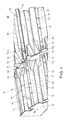
- Fig. 1 schematically shows in section a perspective view of a conveyor drum 10, which is used for a schematically designated Filteransetzmaschine M for Queraxialen transport of rod-shaped articles.
- the conveyor drum 10 has a drum body 12, on the outside in the circumferential direction in regular Distances in two rows receiving wells 14, 24 are formed side by side.
- the rod-shaped article in the receiving troughs 14, 24 are arranged and transported transaxially to a transfer point to a subsequent conveyor drum.
- a filter cigarette 30 is arranged in a receiving trough 24.
- the filter cigarettes 30 conveyed into the receiving cavities 14, 24 have a tobacco rod 32 and a filter 34 or a filter mouthpiece.
- the filter 34 and the tobacco rod 32 are connected to each other by means of a connecting blade (not shown).
- the filter 34 has in the interior in the region of a (rod-shaped) filter section 34.A a capsule 44 filled with a liquid. Since the schematically illustrated capsule 44 is usually located inside the filter 44, it is normally not visible.
- the receiving wells 14 groove portions 141, 142 For receiving filter cigarettes 30 with the pressure-sensitive capsule 44 in the filter 34, the receiving wells 14 groove portions 141, 142, whose trough contours on the circumference of the rod-shaped article in the tobacco rod 34 and the (rod-shaped) filter sections outside the filter section 34.A on the periphery the filter cigarettes 30 come to rest and rest.
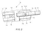
- the receiving wells 14, 24 each have a trough-like recess 144 as a further trough portion, the contour of the recessed recess 144 upon insertion of rod-shaped articles, such as filter cigarettes 30, in the receiving cavities 14 and 24 in the circumferential direction of Filter cigarettes in the area of the filter section 34.A not on Scope of the filter cigarettes or not on the circumference of the filter section 34.A abut. As a result, between the groove-shaped recess 144 and the circumference of the filter section 34.A a permanent gap 36 (see. Fig. 2 ) or a gap opening in the circumferential direction of the filter portion 34.A formed.
- FIG. 2 is an enlarged view of the conveyor drum 10, each formed as a trough portions recesses 144 between the groove portions 141, 142 of the receiving wells 14 and 24, respectively. It can be seen that when the filter cigarette 30 is arranged in the area of the filter section 34.A provided with the capsule 44, an opening-free gap 36 is formed between the trough-like depression 144 of the receiving trough 14 or 24 and the filter section 34.A in the circumferential direction of the filter cigarette.
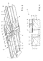
- Fig. 3 is a further embodiment of a further conveyor drum 10 of the tobacco processing industry for the transport of rod-shaped articles or filter cigarettes shown, wherein the receiving wells 14, 24 according to Fig. 3 a recess 144 opposite the groove portions 141, 142, which is formed like a spherical shell, so that when a filter cigarette 30 with a capsule 44 in the filter section 34.A a gap 36 between the recess 144 and the peripheral surface of the filter 34 in the filter section 34.A in which the capsule 44 is arranged, formed in the circumferential direction of the filter portion 34.A.
- Fig. 4 is a schematic cross section through the drum body 12 in the region of two opposite receiving wells 14, 24 of Fig. 3 shown in detail.
- the depressions 144 in the receiving cavities 14 and 24, which are in the form of depression portions, are each formed without suction bores.
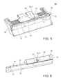
- Fig. 5 is a perspective view schematically a roller block 50 for a rolling device on a conveyor drum of a machine of the tobacco-processing industry M, in particular Filteransetzmaschine shown.
- the roller block 50 forms, in cooperation with a (not shown for reasons of clarity) roller drum from a rolling channel for rod-shaped articles, in particular filter cigarettes, to wrap glued connection leaflets around the joints of groups formed from cigarettes and filter plugs in the trained rolling channel.
- the roller block 50 has on the input side of the rolling channel on a rigid launch bar 52 with the rod-shaped articles facing edge surface 51, so that upon entry of the zuge kitten rod-shaped article, the trained rolling channel is tapered on the input side or narrowed.
- the smoking articles such as filter cigarettes 30, in the rolling channel in rotation, so that a attached to the smoking article groups loose compound leaflet is rolled around the smoking article groups.
- the input-side start bar 52 is formed on its longitudinal side with one or more (trough-like) depressions 54 in the edge surface 51, so that upon entry of the filter cigarettes 30 in the region of the filter section 34.A with the Capsule 44 through the recess 54, these are pressed less when introduced into the rolling channel.
- Fig. 6 is an enlarged detail view Fig. 5 in the region of the recess 54 for the arranged in the filter section 34.
- the launch bar 52 has a corresponding recess 54 for each bar section, which is formed with a capsule 44.
- the second recess of the start bar 54 for the schematically indicated capsule 44 of the (single long) filter cigarette 30 is in FIGS. 5 and 6 not visible.
Landscapes
- Manufacturing Of Cigar And Cigarette Tobacco (AREA)
- Cigarettes, Filters, And Manufacturing Of Filters (AREA)
- Attitude Control For Articles On Conveyors (AREA)
Abstract
Description
Die Erfindung betrifft eine Fördertrommel der Tabak verarbeitenden Industrie zum queraxialen Fördern von stabförmigen Artikeln mit in Umfangsrichtung der Fördertrommel angeordneten, vorzugsweise nutförmigen, Aufnahmemulden für die stabförmigen Artikel.The invention relates to a conveyor drum of the tobacco-processing industry for Queraxialen conveying rod-shaped articles arranged in the circumferential direction of the conveyor drum, preferably groove-shaped, receiving troughs for the rod-shaped article.
Außerdem betrifft die Erfindung eine Verwendung einer Fördertrommel sowie ein Verfahren und eine Maschine der Tabak verarbeitenden Industrie, insbesondere Filteransetzmaschine, zur Herstellung von stabförmigen Artikeln der Tabak verarbeitenden Industrie. Ferner betrifft die Erfindung eine Einrichtung zum Rollen von stabförmigen Artikeln der Tabak verarbeitenden Industrie.Moreover, the invention relates to a use of a conveyor drum and a method and a machine of the tobacco processing industry, in particular filter attachment machine, for the production of rod-shaped articles of the tobacco-processing industry. Furthermore, the invention relates to a device for rolling rod-shaped articles of the tobacco processing industry.
Unter der Bezeichnung "MAX" ist eine Filteransetzmaschine der HAUNI Maschinenbau AG, Hamburg, bekannt.Under the name "MAX" is a filter attachment of HAUNI Maschinenbau AG, Hamburg, known.
Als Filteransetzmaschine wird eine Vorrichtung bzw. Maschine zur Herstellung von Filterzigaretten verstanden mit Mitteln zur Aufnahme von Tabakstöcken doppelter Länge mit Mitteln zum Schneiden dieser doppeltlangen Tabakstöcke in Tabakstöcke einfacher Länge, mit Mitteln zum Einbringen von Filterstopfen doppelter Länge zwischen die Tabakstöcke einfacher Länge, mit Mitteln zum Verbinden des doppeltlangen Filterstopfens mit den beiden Tabakstöcken einfacher Länge durch Umhüllen mit einem als Verbindungsblättchen ausgebildeten Belagpapierblättchen, das mittels einer Schneideinrichtung von einem zugeführten Belagpapierstreifen abgetrennt wird, mit Mitteln zum nachfolgenden Ausführen eines Trennschnitts durch den doppeltlangen Filterstopfen, so dass Filterzigaretten normaler Gebrauchslänge entstehen.As filter attachment machine is a device or machine for the production of filter cigarettes understood with means for receiving tobacco rods of double length with means for cutting these double-length tobacco sticks in tobacco sticks simple length, with means for introducing filter plug double length between the tobacco sticks simple length, with means for Connecting the double-length filter plug to the two single-length tobacco rods by wrapping with a tipping paper leaflet, which is severed by means of a cutter from a tipping paper strip supplied with means for subsequently performing a severing cut through the double-length filter plug to form normal-length filter cigarettes.
Wird eine Folge von queraxial hintereinander angeordneten Tabakstock-Filterstopfen-Tabakstock-Gruppen als einbahniger Materialstrom einer Belageinrichtung zugeführt, so handelt es sich um eine einbahnige Filteransetzmaschine. Bei einer doppelbahnigen Filteransetzmaschine werden zwei Materialströme mit Artikeln zu mindestens einer Belageinrichtung gefördert. Insbesondere sind bei einer doppelbahnigen Filteransetzmaschine zwei Belageinrichtungen für jeweils einen Materialstrom vorgesehen.If a sequence of tobacco rod filter plug tobacco rod groups disposed transaxially behind one another is fed to a padding device as a single-web material flow, then this is a single-web filter attachment machine. In a double-lane filter attachment machine, two streams of material are conveyed with articles to at least one covering device. In particular, in a two-lane filter tying machine, two lining devices are provided for one material flow in each case.
Unter Produkten der Tabak verarbeitenden Industrie werden im Rahmen der vorliegenden Patentanmeldung insbesondere stabförmige Artikel bzw. Objekte wie Zigaretten, Filterstäbe, Multisegmentfilterstäbe und dergleichen verstanden.In the context of the present patent application, products of the tobacco-processing industry are understood to mean in particular rod-shaped articles or objects such as cigarettes, filter rods, multi-segment filter rods and the like.
Auf Fördertrommeln der eingangs genannten Art werden stabförmige Artikel der Tabak verarbeitenden Industrie, insbesondere Filterstäbe und/oder Filterzigaretten und/oder Tabakstöcke, transportiert, wobei die stabförmigen Artikel in einer oder mehreren Reihen hintereinander angeordnet werden und in queraxialer Richtung gefördert werden. Diese Fördertrommeln werden üblicherweise im Zuge der Konfektionierung von Filterstäben und von Filterzigaretten eingesetzt, wobei Filterstabkomponenten mehrfacher Gebrauchslänge in einem so genannten Querverfahren, d.h. quer zu ihren Längsachsen, durch einmalige oder mehrmalige Unterteilung, Staffelung und Hintereinanderreihung für ihre nachfolgende Verbindung mit weiteren Filterkomponenten oder Rauchartikelkomponenten vorbereitet werden.On conveyor drums of the type mentioned rod-shaped articles of the tobacco processing industry, in particular filter rods and / or filter cigarettes and / or tobacco sticks, transported, the rod-shaped articles in one or more rows one behind the other be arranged and conveyed in the transverse axial direction. These conveyor drums are usually used in the course of the assembly of filter rods and filter cigarettes, wherein filter rod components multiple use length in a so-called transverse process, ie transverse to their longitudinal axes, prepared by single or multiple subdivision, staggering and sequential series for their subsequent connection with other filter components or smoking article components become.
Ferner sind Zigarettenprodukte bekannt, die als wesentlichen Bestandteil des Filters eine oder mehrere Kapseln haben, die mit einer Flüssigkeit, z.B. Menthol, gefüllt ist bzw. sind. Die Kapsel wird unmittelbar, bevor die Zigarette entzündet wird, durch den Raucher durch Druck auf den Filter aufgebrochen, wodurch die Flüssigkeit freigesetzt wird und sich das Aroma der Flüssigkeit entfaltet. Damit dieses gewährleistet ist, ist es notwendig, die Qualität des Zigarettenproduktes zu gewährleisten. Die Kapsel muss, wenn das Zigarettenprodukt verkauft wird, gefüllt sein und einwandfrei im Filter positioniert sein.Furthermore, cigarette products are known which, as an essential part of the filter, have one or more capsules which are filled with a liquid, e.g. Menthol, is filled or are. The capsule is broken up immediately before the cigarette is ignited by the smoker by pressure on the filter, whereby the liquid is released and the aroma of the liquid unfolds. To ensure this, it is necessary to ensure the quality of the cigarette product. The capsule must be filled when the cigarette product is sold and properly positioned in the filter.
Ausgehend von diesem Stand der Technik besteht die Aufgabe der Erfindung darin, bei der Herstellung von Filterzigaretten, die beispielsweise Filterkapseln bzw. druckempfindliche Objekte aufweisen, eine sanfte Behandlung der stabförmigen Artikel während der Förderung beispielsweise an einer Filteransetzmaschine zu ermöglichen.Based on this prior art, the object of the invention is to allow in the production of filter cigarettes, for example, the filter capsules or pressure-sensitive objects, a gentle treatment of the rod-shaped article during the promotion, for example, to a filter attachment.
Gelöst wird diese Aufgabe durch eine Fördertrommel der Tabak verarbeitenden Industrie zum queraxialen Fördern von stabförmigen Artikeln mit in Umfangsrichtung der Fördertrommel angeordneten, vorzugsweise nutförmigen, Aufnahmemulden für die stabförmigen Artikel, wobei in den Aufnahmemulden stabförmige Artikel mit einem in einem stabförmigen Artikelabschnitt eingebrachten druckempfindlichen, vorzugsweise mit einer Substanz gefüllten, Objekt, insbesondere Kapsel, zur queraxialen Förderung angeordnet werden oder sind, die dadurch weitergebildet wird, dass die Aufnahmemulden in Längsrichtung der Aufnahmemulden wenigstens einen ersten nutförmigen Muldenabschnitt zur teilweise, vorzugsweise formschlüssigen, Anlage an den nicht mit einem Objekt versehenen stabförmigen Artikelabschnitt der stabförmigen Artikel aufweisen, wobei in Längsrichtung der Aufnahmemulden neben dem ersten Muldenabschnitt ein zweiter nutförmiger Muldenabschnitt für den stabförmigen Artikel ausgebildet ist, wobei der zweite Muldenabschnitt in Längsrichtung der Aufnahmemulde gegenüber dem ersten Muldenabschnitt mit einer wannenartigen Vertiefung ausgebildet ist.This object is achieved by a conveyor drum of the tobacco-processing industry for Queraxialen conveyance of rod-shaped articles arranged in the circumferential direction of the conveyor drum, preferably groove-shaped, receiving troughs for the rod-shaped Article, wherein in the receiving troughs rod-shaped articles with a introduced in a rod-shaped article section pressure-sensitive, preferably filled with a substance, object, in particular capsule, are arranged for Queraxialen promotion or further developed by the receiving troughs in the longitudinal direction of the receiving wells at least one first groove-shaped trough portion for partially, preferably form-fitting, bearing on the not provided with an object rod-shaped article portion of the rod-shaped article, wherein in the longitudinal direction of the receiving wells next to the first trough portion, a second groove-shaped trough portion for the rod-shaped article is formed, wherein the second trough portion in the longitudinal direction the receiving trough is formed with respect to the first trough portion with a trough-like depression.
Die Erfindung beruht auf dem Gedanken, dass bei einer Filteransetzmaschine die Fördertrommeln im Bereich der Filter oder Filterabschnitte, die im Inneren druckempfindliche Objekte, insbesondere Kapseln oder dergleichen, aufweisen für die queraxiale Förderung der Filterzigaretten bzw. der stabförmigen Artikel mit einer Vertiefung oder einer Ausnehmung in den Aufnahmemulden auszubilden, wobei die Vertiefung bzw. Ausnehmung der Aufnahmemulden in diesem Bereich für die Artikelabschnitte mit den Objekten keinen Kontakt mit dem entsprechenden Abschnitt des stabförmigen Artikels bzw. der Filterzigarette hat. Die anderen objekt- oder kapselfreien Artikelabschnitte der Filterzigaretten bzw. der stabförmigen Artikel liegen in den Muldenabschnitten der Aufnahmemulden jeweils an, so dass die Muldenkontur des ersten Muldenabschnitts der Aufnahmemulden beim Einbringen der stabförmigen Artikel in die Aufnahmemulde an den stabförmigen Artikel anliegt bzw. teilweise in Kontakt mit dem darin angeordneten stabförmigen objektfreien Artikelabschnitt ist.The invention is based on the idea that in a filter attachment the conveyor drums in the region of the filter or filter sections, the inside pressure-sensitive objects, in particular capsules or the like, have for Queraxiale promotion of filter cigarettes or the rod-shaped article with a recess or a recess in form the receiving wells, wherein the recess or recess of the receiving wells in this area for the article sections with the objects has no contact with the corresponding portion of the rod-shaped article or the filter cigarette. The other object or capsule-free article sections of the filter cigarettes or the rod-shaped articles are in the trough portions of the receiving wells, so that the trough contour of the first trough portion of the receiving troughs when inserting the rod-shaped article in the receiving trough rests against the rod-shaped article or partially in contact with the rod-shaped object-free article section arranged therein.
Im Rahmen der Erfindung handelt es sich bei den druckempfindlichen Objekten für die Filterstäbe bzw. Filterabschnitte um Kapseln mit einer festen Hülle, die mit einer Flüssigkeit gefüllt sind. Die Flüssigkeit enthält üblicherweise Geschmacksstoffe oder Duftstoffe, beispielsweise Menthol. Zur Verwendung bricht ein Raucher die Kapsel vor dem Rauchen durch Druck auf den Filter auf und zündet die Zigarette anschließend an. Durch den Druck auf die Kapsel im Filter wird die Flüssigkeit der Kapsel freigesetzt, so dass sich das Aroma der Flüssigkeit entfaltet. Diese Vorgehensweise bietet ein intensives oder frisches Geschmackserlebnis für den Raucher.In the context of the invention, the pressure-sensitive objects for the filter rods or filter sections are capsules with a solid shell, which are filled with a liquid. The liquid usually contains flavors or fragrances, for example menthol. To use a smoker breaks the capsule before smoking by pressure on the filter and then ignites the cigarette. The pressure on the capsule in the filter releases the liquid of the capsule so that the aroma of the liquid unfolds. This procedure provides an intense or fresh taste sensation for the smoker.
Entsprechende Kapseln weisen typischerweise einen Durchmesser von 3 bis 3,5 mm auf, können aber auch entsprechend kleiner oder größer sein. Darüber hinaus können als Objekte auch harte Objekte Verwendung finden sowie kleinere oder größere Partikel, beispielsweise Kugeln oder zylindrische Objekte aus Aktivkohle, Extrudaten oder anderen Filtermaterialien oder Zusätzen.Corresponding capsules typically have a diameter of 3 to 3.5 mm, but may also be correspondingly smaller or larger. In addition, as objects also hard objects can be used as well as smaller or larger particles, such as spheres or cylindrical objects made of activated carbon, extrudates or other filter materials or additives.
Dadurch, dass bei der Herstellung von stabförmigen Artikeln bzw. von Filterzigaretten mit druckempfindlichen Kapseln oder dergleichen für den jeweiligen Bereich des stabförmigen Artikelabschnitts mit der Kapsel an den Aufnahmemulden eine wannenartige Vertiefung bzw. Aussparung vorgesehen ist, wodurch die Vertiefung keinen Kontakt mit dem, die Kapsel aufweisenden Artikelabschnitt aufweist, wird die Druckkraft, die während des Produktionsprozesses beispielsweise an einer Filteransetzmaschine auf den Filterabschnitt während der queraxialen Förderung wirkt, durch die Ausnehmung sowie Vertiefung in der Trommelmulde oder den Aufnahmemulden verringert. Hierdurch wird beim Transport und bei der Herstellung der Filterzigaretten der Artikelabschnitt mit den druckempfindlichen Kapseln schonend behandelt und in den Aufnahmemulden sanft transportiert. Insgesamt wird dadurch die mechanische Belastung der Filterzigaretten im Abschnitt mit der druckempfindlichen Kapsel herabgesetzt, während die kapselfreien Artikelabschnitte der Filterzigaretten in den Aufnahmemulden durch Beaufschlagung mit Unterdruck anliegen.Characterized in that in the production of rod-shaped articles or of filter cigarettes with pressure-sensitive capsules or the like for the respective region of the rod-shaped article section with the capsule at the receiving wells a trough-like depression or recess is provided, whereby the depression no contact with the, the capsule Having exhibiting article section, the pressure force which acts during the production process, for example on a filter tipping on the filter section during the transverse axial promotion, through the recess and depression in the drum trough or the receiving wells is reduced. As a result, the article section with the pressure-sensitive capsules is gently treated during transport and in the production of filter cigarettes and gentle in the receiving troughs transported. Overall, this reduces the mechanical stress on the filter cigarettes in the section with the pressure-sensitive capsule, while the capsule-free article sections of the filter cigarettes rest in the receiving troughs by applying negative pressure.
Die nutförmigen Aufnahmemulden für die stabförmigen Artikel weisen in Längsrichtung jeweils mehrere nutförmige Muldenabschnitte auf, wobei ein erster Muldenabschnitt zur Aufnahme eines Artikelabschnitts der stabförmigen Artikel vorgesehen ist und die Muldenkontur des ersten Muldenabschnitts am darin angeordneten Artikelabschnitt in Umfangsrichtung anliegt, und wobei in Längsrichtung der Aufnahmemulden neben dem ersten Muldenabschnitt jeweils ein zweiter nutförmiger Muldenabschnitt vorgesehen ist. Hierbei ist der zweite Muldenabschnitt gegenüber dem ersten Muldenabschnitt in Längsrichtung und in Umfangsrichtung der Aufnahmemulden mit einer wannenartigen Vertiefung ausgebildet, so dass die Muldenkontur des zweiten Muldenabschnitts gegenüber der am Artikelabschnitt oder am Artikel anliegenden Muldenkontur des benachbarten ersten Muldenabschnitts versetzt zurückversetzt ist. Dadurch ist die Muldenkontur des zweiten Muldenabschnitts in Längsrichtung und die Umfangsrichtung der Aufnahmemulden gegenüber dem benachbarten ersten Muldenabschnitt mit einer Art Stufe abgesetzt ausgebildet.The groove-shaped receiving troughs for the rod-shaped articles each have a plurality of groove-shaped trough sections in the longitudinal direction, wherein a first trough section for receiving an article section of the rod-shaped article is provided and the trough contour of the first trough section abuts the article section arranged therein in the circumferential direction, and wherein in the longitudinal direction of the receiving troughs next A second groove-shaped depression portion is provided in each case for the first depression portion. In this case, the second trough portion opposite the first trough portion in the longitudinal direction and in the circumferential direction of the receiving wells is formed with a trough-like depression, so that the trough contour of the second trough portion is set back staggered with respect to the lying on the article section or the article trough contour of the adjacent first trough portion. Thereby, the trough contour of the second trough portion in the longitudinal direction and the circumferential direction of the receiving trough with respect to the adjacent first trough portion with a kind of stepped step is formed.
Dazu ist vorgesehen, dass die Aufnahmemulden wenigstens einen ersten Muldenabschnitt zur teilweise, vorzugsweise formschlüssigen, Anlage an den nicht mit einem Objekt versehenen stabförmigen Artikelabschnitt der stabförmigen Artikel in Umfangsrichtung der stabförmigen Artikel und einen zweiten Muldenabschnitt für den mit einem druckempfindlichen Objekt versehenen stabförmigen Artikelabschnitt aufweisen, wobei der zweite Muldenabschnitt gegenüber dem ersten Muldenabschnitt eine wannenartige Vertiefung aufweist, so dass die wannenartige Vertiefung des zweiten Muldenabschnitts in Umfangsrichtung der stabförmigen Artikel im Bereich des Artikelabschnitts der stabförmigen Artikel mit dem Objekt keinen Kontakt mit dem Artikelabschnitt hat.For this purpose, it is provided that the receiving troughs have at least a first trough portion for partially, preferably positively locking, contact with the not provided with an object rod-shaped article portion of the rod-shaped article in the circumferential direction of the rod-shaped article and a second trough portion for the provided with a pressure-sensitive object rod-shaped article section, wherein the second trough portion opposite the first trough portion has a trough-like depression, so that the trough-like depression of the second trough portion in the circumferential direction of the rod-shaped article in the region of the article portion of the rod-shaped article with the object has no contact with the article section.
Darüber hinaus ist in einer Ausgestaltung der Fördertrommel vorgesehen, dass die Aufnahmemulden einen ersten Muldenabschnitt und einen dritten Muldenabschnitt aufweisen, wobei die Muldenkontur des ersten Muldenabschnitts und die Muldenkontur des dritten Muldenabschnitts in Umfangsrichtung an den stabförmigen Artikeln teilweise anliegen oder teilweise in Kontakt mit den stabförmigen Artikelabschnitten, insbesondere mit Artikelabschnitten ohne druckempfindliches Objekt, der stabförmigen Artikel in Umfangsrichtung bringbar sind, wobei zwischen dem ersten Muldenabschnitt und dem dritten Muldenabschnitt der zweite Muldenabschnitt mit der wannenartigen Vertiefung für den mit einem Objekt versehenen stabförmigen Artikelabschnitt der stabförmigen Artikel vorgesehen ist. Hierdurch ist auf beiden Seiten der wannenartigen Vertiefung ein Muldenabschnitt der Aufnahmemulden vorgesehen, um die zu transportierenden stabförmigen Artikel auf der Fördertrommel beidseits der Vertiefung sicher zu halten.In addition, in one embodiment of the conveyor drum is provided that the receiving wells have a first trough portion and a third trough portion, the trough contour of the first trough portion and the trough contour of the third trough portion in the circumferential direction of the rod-shaped articles partially or partially in contact with the rod-shaped article sections , in particular with article sections without pressure-sensitive object, the rod-shaped article can be brought in the circumferential direction, wherein provided between the first trough portion and the third trough portion of the second trough portion with the trough-like recess for the object-provided rod-shaped article portion of the rod-shaped article. As a result, a trough portion of the receiving troughs is provided on both sides of the trough-like depression in order to keep the transportable rod-shaped articles on the conveyor drum on both sides of the well.
Insbesondere ist hierzu vorgesehen, dass der zweite Muldenabschnitt der Aufnahmemulden keine Saugbohrung aufweist und/oder der zweite Muldenabschnitt eine durchbrechungsfreie Fläche, insbesondere Oberfläche, aufweist, wobei der Artikelabschnitt der stabförmigen Artikel mit dem druckempfindlichen Objekt der durchbrechungsfreien Fläche unter Ausbildung eines in Umfangsrichtung des stabförmigen Artikels unterbrechungsfreien Spalts gegenüber angeordnet oder anordbar ist.In particular, it is provided for this purpose that the second trough portion of the receiving wells has no suction bore and / or the second trough portion has a non-piercing surface, in particular surface, wherein the article portion of the rod-shaped article with the pressure-sensitive object of the non-disruptive surface to form a circumferential direction of the rod-shaped article uninterrupted gap arranged opposite or can be arranged.
Ferner zeichnet sich eine Ausführungsform der Fördertrommel dadurch aus, dass in Umfangsrichtung der Fördertrommel zwei nebeneinander angeordnete Reihen mit Aufnahmemulden vorgesehen sind, wobei die Aufnahmemulden jeder Reihe jeweils mindestens einen ersten Muldenabschnitt und einen zweiten Muldenabschnitt für die stabförmigen Artikel aufweisen.Furthermore, an embodiment of the conveyor drum is characterized in that two juxtaposed rows are provided with receiving troughs in the circumferential direction of the conveyor drum, wherein the receiving troughs of each row each have at least a first trough portion and a second trough portion for the rod-shaped article.
Die Fördertrommeln werden vorzugsweise an einer Trommelmaschine, insbesondere einer Filteransetzmaschine oder dergleichen, zur Herstellung von stabförmigen Artikeln, insbesondere Filterzigaretten, eingesetzt, wodurch bei der Herstellung von Filterzigaretten mit druckempfindlichen Kapseln im Filterabschnitt die Filterzigaretten schonend auf den Fördertrommeln gefördert werden, wodurch zusätzlich auch die Form der mechanisch fragilen und sensiblen Filterzigaretten erhalten wird.The conveyor drums are preferably used on a drum machine, in particular a filter attachment machine or the like for the production of rod-shaped articles, in particular filter cigarettes, whereby the filter cigarettes are gently promoted on the conveyor drums in the production of filter cigarettes with pressure-sensitive capsules in the filter section, which additionally also the shape the mechanically fragile and sensitive filter cigarettes is obtained.
Ferner wird die Aufgabe gelöst durch eine Verwendung einer Fördertrommel zum queraxialen Fördern von stabförmigen Artikeln der Tabak verarbeitenden Industrie, insbesondere von mit einem in einem stabförmigen Artikelabschnitt eingebrachten druckempfindlichen, vorzugsweise mit einer Substanz gefüllten, Objekt, insbesondere Kapsel, stabförmigen Artikeln in einer Maschine der Tabak verarbeitenden Industrie, insbesondere Filteransetzmaschine. Zur Vermeidung von Wiederholungen wird auf die obigen Ausführungen zur Fördertrommel ausdrücklich verwiesen.Furthermore, the object is achieved by a use of a conveyor drum for Queraxialen conveyance of rod-shaped articles of the tobacco industry, especially with a introduced in a rod-shaped article section pressure-sensitive, preferably filled with a substance, object, in particular capsule, rod-shaped articles in a machine of tobacco processing industry, in particular Filteransetzmaschine. To avoid repetition, reference is expressly made to the above remarks on the conveyor drum.
Außerdem wird die Aufgabe gelöst durch ein Verfahren zum Herstellen von stabförmigen Artikeln der Tabak verarbeitenden Industrie, insbesondere von mit einem in einem stabförmigen Artikelabschnitt eingebrachten druckempfindlichen, vorzugsweise mit einer Substanz gefüllten, Objekt, insbesondere Kapsel, stabförmigen Artikeln, insbesondere Filterzigaretten, wobei die stabförmigen Artikel unter Verwendung einer voranstehend beschriebenen Fördertrommel queraxial gefördert werden.In addition, the object is achieved by a method for producing rod-shaped articles of the tobacco-processing industry, in particular with a introduced in a rod-shaped article section pressure-sensitive, preferably filled with a substance, object, in particular capsule, rod-shaped articles, in particular filter cigarettes, wherein the rod-shaped article under Use of a conveying drum described above are conveyed transversely.
Ferner wird die Aufgabe gelöst durch eine Einrichtung zum Rollen von stabförmigen Artikeln der Tabak verarbeitenden Industrie, insbesondere von Filterzigaretten mit einem im Filter angeordneten druckempfindlichen, vorzugsweise mit einer Substanz versehenen, Objekt, insbesondere in Kombination mit einer voranstehend beschriebenen Fördertrommel, mit einem eine Rollfläche aufweisenden Rollförderer und einer zugeordneten Gegenrollfläche, die zum Umrollen der stabförmigen Artikel einen Rollkanal bilden und relativ zueinander bewegbar sind, und mit einer am Einlass des Rollkanals angeordneten starren Startleiste, die dadurch weitergebildet wird, dass die Startleiste mehrere Startleistenabschnitte aufweist, wobei ein erster Startleistenabschnitt für einen stabförmigen Artikelabschnitt vorgesehen ist, wobei der stabförmige Artikelabschnitt nicht mit einem druckempfindlichen, vorzugsweise mit einer Substanz gefüllten, Objekt versehen ist, und wobei ein zweiter Startleistenabschnitt der Startleiste für einen weiteren stabförmigen Artikelabschnitt mit einer wannenförmigen Vertiefung vorgesehen ist, wobei der weitere stabförmige Artikelabschnitt mit einem druckempfindlichen, vorzugsweise mit einer Substanz gefüllten, Objekt versehen ist, wobei der zweite Startleistenabschnitt gegenüber dem ersten Startleistenabschnitt mit einem vorbestimmten Abstand zurückversetzt ist, so dass der Einlass des Rollkanals im Bereich des ersten Startleistenabschnitts gegenüber dem Bereich mit dem zweiten Startleistenabschnitt eine geringere Höhe aufweist und/oder verengt ist.Furthermore, the object is achieved by a device for rolling rod-shaped articles of the tobacco-processing industry, in particular filter cigarettes with a pressure-sensitive, preferably provided with a substance in the filter object, in particular in combination with a conveying drum described above, having a rolling surface having Rolling conveyor and an associated counter rolling surface, which form a rolling channel for rewinding the rod-shaped articles and are movable relative to each other, and with a arranged at the inlet of the rolling channel rigid launch bar, which is further developed in that the launch bar has a plurality of starter bar sections, wherein a first start bar section for a rod-shaped article section is provided, wherein the rod-shaped article section is not provided with a pressure-sensitive, preferably filled with a substance object, and wherein a second start strip section d he launch bar is provided for a further rod-shaped article section with a trough-shaped depression, wherein the further rod-shaped article section is provided with a pressure-sensitive, preferably filled with a substance object, the second starting bar portion is set back relative to the first starting bar portion with a predetermined distance, so that the inlet of the rolling channel in the region of the first starting strip section has a lower height than the region with the second starting strip section and / or is narrowed.
Der Vorteil dieser Lösung besteht darin, die durch eine Einrichtung zum Rollen von stabförmigen Gegenständen bereitgestellt wird, wobei die Vorrichtung zum Herumwickeln von beleimten Verbindungsblättchen um die Stoßstellen von aus stabförmigen Tabakartikeln und Filterstopfen oder Filtermundstück gebildeten Gruppen dient. Hierbei sind ein eine Rollfläche aufweisender Rollförderer und eine zugeordnete ortsfeste Gegenrollfläche vorgesehen, wobei die Rollfläche und die Gegenrollfläche zum Umrollen der Gruppen mit den Verbindungsblättchen einen Rollkanal bilden und relativ zueinander bewegbar sind.The advantage of this solution is that provided by means for rolling rod-shaped articles, the device for wrapping glued connection sheets serves around the joints of groups formed of rod-shaped tobacco articles and filter plug or filter mouthpiece. In this case, a roller conveyor having a rolling surface and an associated stationary counter rolling surface are provided, wherein the rolling surface and the counter rolling surface for reeling the groups with the connecting blades form a rolling channel and are movable relative to each other.
Hierbei ist an der ortsfesten Gegenrollfläche vor dem Einlauf der Rauchartikelgruppe in den Rollkanal eine Startleiste angeordnet, wobei bei Eintritt von stabförmigen Artikeln in den Rollkanal diese in Rollung versetzt werden. Hierzu ist gemäß der Erfindung vorgesehen, dass die Startleiste mehrere Startleistenabschnitte aufweist, die unterschiedliche Höhen aufweisen, so dass der Einlass des Rollkanals aufgrund der unterschiedlichen Höhen der Startleiste durch die Vertiefung entlang der Startleiste verengt oder weniger stark verengt ist. Dabei ist der mit einer wannenförmigen Vertiefung vorgesehene zweite Startleistenabschnitt der Startleiste für Artikelabschnitte mit einem druckempfindlichen Objekt vorgesehen, so dass die mechanische Belastung im Bereich des zurückversetzten Startleistenabschnitts geringer ist als die mechanische Belastung des Artikelabschnitts im verengten Einlass mit dem ersten Startleistenabschnitt für die objektfreien Artikelstababschnitte der zu umwickelnden Rauchartikelkomponentengruppen.Here, a launch bar is arranged on the stationary counter rolling surface before the inlet of the smoking article group in the rolling channel, which are offset when entering rod-shaped articles in the rolling channel these in roll. For this purpose, it is provided according to the invention that the launch bar has a plurality of start strip sections, which have different heights, so that the inlet of the rolling channel is narrowed or less narrowed due to the different heights of the launch bar through the depression along the launch bar. In this case, provided with a trough-shaped depression second start bar portion of the launch bar for article sections with a pressure-sensitive object is provided so that the mechanical stress in the recessed start strip portion is less than the mechanical load of the article section in the narrowed inlet with the first start bar portion for the article-free article rod sections of to be wrapped smoking article component groups.
Darüber hinaus zeichnet sich die Einrichtung dadurch aus, dass die Startleiste zwei zweite Startleistenabschnitte für einen doppeltlangen stabförmigen Artikel, insbesondere doppeltlange Filterzigaretten mit wenigstens zwei druckempfindlichen Objekten, wobei die zweiten Startleistenabschnitte für jeweils einen mit einem druckempfindlichen Objekt ausgebildeten stabförmigen Artikelabschnitt mit einer Vertiefung vorgesehen ist.In addition, the device is characterized in that the launch bar two second start strip sections for a double-length rod-shaped article, in particular double-length filter cigarettes with at least two pressure-sensitive objects, wherein the second start bar sections is provided for each one formed with a pressure-sensitive object rod-shaped article section with a recess.
Vorzugsweise wird durch die Kombination einer erfindungsgemäßen, oben beschriebenen, Fördertrommel der Tabak verarbeitenden Industrie mit einer beschriebenen Einrichtung zum Rollen von stabförmigen Artikeln der Tabak verarbeitenden Industrie eine Anordnung zum queraxialen Fördern von stabförmigen Artikeln, insbesondere von stabförmigen Artikeln mit in einem stabförmigen Artikelabschnitt eingebrachten druckempfindlichen, vorzugsweise mit einer Substanz gefüllten, Objekten bzw. Kapseln bereitgestellt.Preferably, the combination of a conveying drum according to the invention described above, the tobacco processing industry with a described device for rolling rod-shaped articles of the tobacco processing industry, an arrangement for Queraxialen conveying rod-shaped articles, in particular rod-shaped articles with incorporated in a rod-shaped article section pressure-sensitive, preferably filled with a substance, objects or capsules provided.
Außerdem wird die Aufgabe gelöst durch eine Maschine der Tabak verarbeitenden Industrie, insbesondere Filteransetzmaschine, zur Herstellung von stabförmigen Artikeln der Tabak verarbeitenden Industrie, insbesondere von mit einem in einem stabförmigen Artikelabschnitt eingebrachten druckempfindlichen, vorzugsweise mit einer Substanz gefüllten, Objekt, insbesondere Kapsel, stabförmigen Artikeln, die mit einer erfindungsgemäßen Fördertrommel und/oder einer erfindungsgemäßen Einrichtung zum Rollen von stabförmigen Artikeln der Tabak verarbeitenden Industrie ausgebildet ist. Zur Vermeidung von Wiederholungen wird auf die obigen Ausführungen ausdrücklich verwiesen.In addition, the object is achieved by a machine of the tobacco-processing industry, in particular filter attachment machine, for the production of rod-shaped articles of the tobacco-processing industry, in particular with a introduced in a rod-shaped article section pressure-sensitive, preferably filled with a substance, object, in particular capsule, rod-shaped articles , which is formed with a conveyor drum according to the invention and / or a device according to the invention for rolling rod-shaped articles of the tobacco-processing industry. To avoid repetition, reference is expressly made to the above statements.
Weitere Merkmale der Erfindung werden aus der Beschreibung erfindungsgemäßer Ausführungsformen zusammen mit den Ansprüchen und den beigefügten Zeichnungen ersichtlich. Erfindungsgemäße Ausführungsformen können einzelne Merkmale oder eine Kombination mehrerer Merkmale erfüllen.Further features of the invention will become apparent from the description of embodiments according to the invention together with the claims and the accompanying drawings. Embodiments of the invention may satisfy individual features or a combination of several features.
Die Erfindung wird nachstehend ohne Beschränkung des allgemeinen Erfindungsgedankens anhand von Ausführungsbeispielen unter Bezugnahme auf die Zeichnungen beschrieben, wobei bezüglich aller im Text nicht näher erläuterten erfindungsgemäßen Einzelheiten ausdrücklich auf die Zeichnungen verwiesen wird. Es zeigen:
- Fig. 1
- im Ausschnitt eine Fördertrommel der Tabak verarbeitenden Industrie für eine Filteransetzmaschine,
- Fig. 2
- schematisch eine Draufsicht auf die Fördertrommel im Ausschnitt,
- Fig. 3
- schematisch eine perspektivische Ansicht einer weiteren Fördertrommel der Tabak verarbeitenden Industrie für eine Filteransetzmaschine im Ausschnitt,
- Fig. 4
- schematisch einen Querschnitt durch Aufnahmemulden der Fördertrommel aus
Fig. 3 im Ausschnitt, - Fig. 5
- schematisch eine perspektivische Darstellung eines Rollklotzes für eine Rolleinrichtung zum Umrollen von stabförmigen Artikeln an einer Fördertrommel der Tabak verarbeitenden Industrie und
- Fig. 6
- im Ausschnitt schematisch eine Ansicht der Startleiste in einer Detailansicht.
- Fig. 1
- in section a conveyor drum of the tobacco processing industry for a filter attachment machine,
- Fig. 2
- schematically a plan view of the conveyor drum in the neck,
- Fig. 3
- schematically a perspective view of another conveyor drum of the tobacco processing industry for a Filteransetzmaschine in excerpt,
- Fig. 4
- schematically a cross section through receiving troughs of the conveyor drum
Fig. 3 in the neckline, - Fig. 5
- schematically a perspective view of a roll block for a rolling device for rolling rod-shaped articles on a conveyor drum of the tobacco-processing industry and
- Fig. 6
- In the detail, a schematic view of the start bar in a detail view.
In den Zeichnungen sind jeweils gleiche oder gleichartige Elemente und/oder Teile mit denselben Bezugsziffern versehen, so dass von einer erneuten Vorstellung jeweils abgesehen wird.In the drawings, the same or similar elements and / or parts are provided with the same reference numerals, so that apart from a new idea each.
Wie aus
Zur Aufnahme von Filterzigaretten 30 mit der druckempfindlichen Kapsel 44 im Filter 34 weisen die Aufnahmemulden 14 Nutabschnitte 141, 142 auf, deren Muldenkonturen an den Umfang der stabförmigen Artikel im Bereich des Tabakstocks 34 und der (stabförmigen) Filterabschnitte außerhalb des Filterabschnitts 34.A am Umfang der Filterzigaretten 30 zur Anlage kommen sowie anliegen. Zwischen dem Nutabschnitt 141 und 142 weisen die Aufnahmemulden 14, 24 jeweils eine wannenartige Vertiefung 144 als weiteren Muldenabschnitt auf, wobei die Kontur der zurückversetzten Vertiefung 144 bei Einbringen von stabförmigen Artikeln, wie z.B. Filterzigaretten 30, in die Aufnahmemulden 14 bzw. 24 in Umfangsrichtung der Filterzigaretten im Bereich des Filterabschnitts 34.A nicht am Umfang der Filterzigaretten bzw. nicht am Umfang des Filterabschnitts 34.A anliegen. Hierdurch ist zwischen der nutförmigen Vertiefung 144 und dem Umfang des Filterabschnitts 34.A ein dauerhafter Spalt 36 (vgl.
In
In
In
Wie aus den
In
Beispielsweise ist eine Vorrichtung zum Umwickeln von beleimten Verbindungsblättchen um die Stoßstelle von aus Zigaretten und Filterstopfen gebildeten Gruppen in
Der Rollklotz 50 weist eingangsseitig des Rollkanals eine starre Startleiste 52 mit einer den stabförmigen Artikeln zugewandten Kantenfläche 51 auf, so dass bei Eintritt der zugeförderten stabförmigen Artikel der ausgebildete Rollkanal eingangsseitig verjüngt bzw. verengt ist. Bei Eintritt werden die Rauchartikel, wie z.B. Filterzigaretten 30, im Rollkanal in Rotation versetzt, so dass ein an die Rauchartikelgruppen angeheftetes loses Verbindungsblättchen um die Rauchartikelgruppen herumgerollt wird.The
Bei der Herstellung von Filterzigaretten mit Kapseln 44 im Filter 34 ist die eingangsseitige Startleiste 52 an ihrer Längsseite mit einer oder mehreren (wannenartigen) Vertiefungen 54 in der Kantenfläche 51 ausgebildet, so dass bei Eintritt der Filterzigaretten 30 im Bereich des Filterabschnitts 34.A mit der Kapsel 44 durch die Vertiefung 54 diese weniger stark beim Einbringen in den Rollkanal gedrückt werden.In the production of filter cigarettes with
In
Alle genannten Merkmale, auch die den Zeichnungen allein zu entnehmenden sowie auch einzelne Merkmale, die in Kombination mit anderen Merkmalen offenbart sind, werden allein und in Kombination als erfindungswesentlich angesehen. Erfindungsgemäße Ausführungsformen können durch einzelne Merkmale oder eine Kombination mehrerer Merkmale erfüllt sein.All mentioned features, including the drawings alone to be taken as well as individual features that are disclosed in combination with other features are considered alone and in combination as essential to the invention. Embodiments of the invention may be accomplished by individual features or a combination of several features.
- 1010
- Fördertrommelconveyor drum
- 1212
- Trommelkörperdrum body
- 1414
- Aufnahmemuldereceiving trough
- 1616
- Saugbohrungsuction bore
- 2424
- Aufnahmemuldereceiving trough
- 3030
- Filterzigarettenfilter cigarettes
- 3232
- Tabakstocktobacco rod
- 3434
- Filterfilter
- 34.A34.A
- Filterabschnittfilter section
- 3636
- Spaltgap
- 4444
- Kapselcapsule
- 5050
- Rollklotzroll Klotz
- 5151
- Kantenflächeedge surface
- 5252
- Startleistelaunch toolbar
- 5454
- Vertiefungdeepening
- 141141
- Nutabschnittgroove
- 142142
- Nutabschnittgroove
- 144144
- Vertiefungdeepening
- MM
- Filteransetzmaschinefilter attachment
Claims (10)
Applications Claiming Priority (1)
| Application Number | Priority Date | Filing Date | Title |
|---|---|---|---|
| DE102013201854.1A DE102013201854A1 (en) | 2013-02-05 | 2013-02-05 | Promotion of rod-shaped articles of the tobacco processing industry with pressure-sensitive objects |
Publications (2)
| Publication Number | Publication Date |
|---|---|
| EP2762014A2 true EP2762014A2 (en) | 2014-08-06 |
| EP2762014A3 EP2762014A3 (en) | 2016-06-08 |
Family
ID=50031203
Family Applications (1)
| Application Number | Title | Priority Date | Filing Date |
|---|---|---|---|
| EP14153621.9A Withdrawn EP2762014A3 (en) | 2013-02-05 | 2014-02-03 | Transport of rod-shaped items from the tobacco processing industry with pressure-sensitive objects |
Country Status (3)
| Country | Link |
|---|---|
| EP (1) | EP2762014A3 (en) |
| CN (1) | CN103960776A (en) |
| DE (1) | DE102013201854A1 (en) |
Cited By (5)
| Publication number | Priority date | Publication date | Assignee | Title |
|---|---|---|---|---|
| EP3141134A3 (en) * | 2015-08-20 | 2017-06-21 | Hauni Maschinenbau GmbH | Transfer drum for the tobacco processing industry |
| WO2017203258A1 (en) * | 2016-05-27 | 2017-11-30 | British American Tobacco (Investments) Limited | Apparatus and method for manufacturing tobacco industry products |
| WO2019142139A1 (en) * | 2018-01-19 | 2019-07-25 | G.D S.P.A. | Rolling bed for smoking articles |
| EP3315032B1 (en) | 2016-10-26 | 2020-09-30 | G.D S.p.A. | Conveyor drum for groups comprising two coaxial cigarette segments separated by at least one double filter comprising at least one fragile filter element |
| US11252990B2 (en) | 2016-05-27 | 2022-02-22 | British American Tobacco (Investments) Limited | Apparatus and method for manufacturing tobacco industry products |
Families Citing this family (4)
| Publication number | Priority date | Publication date | Assignee | Title |
|---|---|---|---|---|
| GB201717567D0 (en) | 2017-10-25 | 2017-12-06 | British American Tobacco Investments Ltd | A filter for a smoking article or an aerosol generating product |
| DE102018104957A1 (en) * | 2018-03-05 | 2019-09-05 | Hauni Maschinenbau Gmbh | Sliding drum of the tobacco processing industry |
| DE102018104956A1 (en) * | 2018-03-05 | 2019-09-05 | Hauni Maschinenbau Gmbh | Conveyor drum of the tobacco processing industry |
| DE102018115933A1 (en) * | 2018-07-02 | 2020-01-02 | Hauni Maschinenbau Gmbh | Multi-segment product manufacturing in the tobacco processing industry |
Citations (2)
| Publication number | Priority date | Publication date | Assignee | Title |
|---|---|---|---|---|
| DE19718322A1 (en) | 1997-04-30 | 1998-11-05 | Hauni Maschinenbau Ag | Winder for glued connecting strips round joins between cigarettes and filter tips |
| EP1629734A1 (en) | 2004-08-30 | 2006-03-01 | Hauni Maschinenbau AG | Drum with rib for a rolling device |
Family Cites Families (6)
| Publication number | Priority date | Publication date | Assignee | Title |
|---|---|---|---|---|
| DE1205434B1 (en) * | 1961-07-07 | 1965-11-18 | Hauni Werke Koerber & Co Kg | Method and device for sorting out cigarettes or other air-permeable rod-shaped objects |
| DE3534453A1 (en) * | 1985-09-27 | 1987-04-02 | Hauni Werke Koerber & Co Kg | CIRCULAR SEAL FOR TESTING ROD-SHAPED ITEMS OF THE TOBACCO PROCESSING INDUSTRY |
| EP0928567B1 (en) * | 1997-06-19 | 2002-05-15 | Japan Tobacco Inc. | Filter mounting apparatus |
| DE102010002590B4 (en) * | 2010-03-04 | 2013-07-04 | Hauni Maschinenbau Ag | Joining rod-shaped articles of the tobacco processing industry |
| EP2813153B1 (en) * | 2012-03-26 | 2022-01-12 | Japan Tobacco, Inc. | Filter mounting device |
| EP2796061A1 (en) * | 2013-04-25 | 2014-10-29 | Tews Elektronik Gmbh&co. Kg | Device and method for measuring capsules in cigarette filters |
-
2013
- 2013-02-05 DE DE102013201854.1A patent/DE102013201854A1/en not_active Ceased
-
2014
- 2014-02-03 EP EP14153621.9A patent/EP2762014A3/en not_active Withdrawn
- 2014-02-07 CN CN201410044887.4A patent/CN103960776A/en active Pending
Patent Citations (2)
| Publication number | Priority date | Publication date | Assignee | Title |
|---|---|---|---|---|
| DE19718322A1 (en) | 1997-04-30 | 1998-11-05 | Hauni Maschinenbau Ag | Winder for glued connecting strips round joins between cigarettes and filter tips |
| EP1629734A1 (en) | 2004-08-30 | 2006-03-01 | Hauni Maschinenbau AG | Drum with rib for a rolling device |
Cited By (8)
| Publication number | Priority date | Publication date | Assignee | Title |
|---|---|---|---|---|
| EP3141134A3 (en) * | 2015-08-20 | 2017-06-21 | Hauni Maschinenbau GmbH | Transfer drum for the tobacco processing industry |
| WO2017203258A1 (en) * | 2016-05-27 | 2017-11-30 | British American Tobacco (Investments) Limited | Apparatus and method for manufacturing tobacco industry products |
| EP3729974A1 (en) * | 2016-05-27 | 2020-10-28 | British American Tobacco (Investments) Limited | Apparatus and method for manufacturing tobacco industry products |
| US11252990B2 (en) | 2016-05-27 | 2022-02-22 | British American Tobacco (Investments) Limited | Apparatus and method for manufacturing tobacco industry products |
| US11540558B2 (en) | 2016-05-27 | 2023-01-03 | British American Tobacco (Investments) Limited | Apparatus and method for manufacturing tobacco industry products |
| US12108782B2 (en) | 2016-05-27 | 2024-10-08 | British American Tobacco (Investments) Limited | Apparatus and method for manufacturing tobacco industry products |
| EP3315032B1 (en) | 2016-10-26 | 2020-09-30 | G.D S.p.A. | Conveyor drum for groups comprising two coaxial cigarette segments separated by at least one double filter comprising at least one fragile filter element |
| WO2019142139A1 (en) * | 2018-01-19 | 2019-07-25 | G.D S.P.A. | Rolling bed for smoking articles |
Also Published As
| Publication number | Publication date |
|---|---|
| CN103960776A (en) | 2014-08-06 |
| EP2762014A3 (en) | 2016-06-08 |
| DE102013201854A1 (en) | 2014-08-07 |
Similar Documents
| Publication | Publication Date | Title |
|---|---|---|
| EP2762014A2 (en) | Transport of rod-shaped items from the tobacco processing industry with pressure-sensitive objects | |
| EP3298909B1 (en) | Manufacture of smoking products | |
| EP2449897A1 (en) | Method and device for inserting objects into a filter rod for the tobacco processing industry | |
| EP3259999A1 (en) | Transport of rod-shaped articles from the tobacco processing industry | |
| EP2661971B1 (en) | Production of filter cigarettes | |
| EP2198725B1 (en) | Swash plate, pusher drum and machine for the tobacco processing industry | |
| EP2363029A1 (en) | Transport drum for the tobacco processing industry | |
| EP1638419B1 (en) | Double-belt filter assembly machine, and production of filter cigarettes | |
| EP2712509B1 (en) | Discharge of rod-shaped articles from the tobacco processing industry | |
| EP3434117B1 (en) | Preparation of rod-like smoking products | |
| DE102015110516A1 (en) | Composing segments of the tobacco processing industry | |
| EP3641572A1 (en) | Method for producing smoking article products | |
| EP1397965B1 (en) | Injection of a medium in filter segments | |
| EP2517582A2 (en) | Suction ring for a conveyor drum in the tobacco processing industry | |
| EP3295810B2 (en) | Production of filter cigarettes | |
| EP3590362B1 (en) | Multisegment product manufacture for the tobacco processing industry | |
| EP1493341B1 (en) | Double line filter assembling machine | |
| DE102013220757B3 (en) | Koaxialzigarettenherstellung | |
| EP2532257B2 (en) | Transport drum for the tobacco processing industry | |
| EP2696709B1 (en) | Conveying rod-shaped articles of the tobacco processing industry | |
| DE102018103635A1 (en) | Multi-segment product manufacturing of the tobacco processing industry | |
| DE102018110468A1 (en) | Removal drum for a machine of the tobacco processing industry | |
| EP2696707B1 (en) | Conveying rod-shaped articles of the tobacco processing industry | |
| DE102013220758A1 (en) | Method for producing rod-shaped articles and strand machine of the tobacco-processing industry | |
| EP2604131A1 (en) | Operation of a filter application machine |
Legal Events
| Date | Code | Title | Description |
|---|---|---|---|
| PUAI | Public reference made under article 153(3) epc to a published international application that has entered the european phase |
Free format text: ORIGINAL CODE: 0009012 |
|
| 17P | Request for examination filed |
Effective date: 20140203 |
|
| AK | Designated contracting states |
Kind code of ref document: A2 Designated state(s): AL AT BE BG CH CY CZ DE DK EE ES FI FR GB GR HR HU IE IS IT LI LT LU LV MC MK MT NL NO PL PT RO RS SE SI SK SM TR |
|
| AX | Request for extension of the european patent |
Extension state: BA ME |
|
| RIC1 | Information provided on ipc code assigned before grant |
Ipc: A24D 3/02 20060101ALI20160113BHEP Ipc: A24C 5/47 20060101ALI20160113BHEP Ipc: A24C 5/32 20060101AFI20160113BHEP |
|
| PUAL | Search report despatched |
Free format text: ORIGINAL CODE: 0009013 |
|
| AK | Designated contracting states |
Kind code of ref document: A3 Designated state(s): AL AT BE BG CH CY CZ DE DK EE ES FI FR GB GR HR HU IE IS IT LI LT LU LV MC MK MT NL NO PL PT RO RS SE SI SK SM TR |
|
| AX | Request for extension of the european patent |
Extension state: BA ME |
|
| RIC1 | Information provided on ipc code assigned before grant |
Ipc: A24C 5/32 20060101AFI20160503BHEP Ipc: A24C 5/47 20060101ALI20160503BHEP Ipc: A24D 3/02 20060101ALI20160503BHEP |
|
| RAP1 | Party data changed (applicant data changed or rights of an application transferred) |
Owner name: HAUNI MASCHINENBAU GMBH |
|
| STAA | Information on the status of an ep patent application or granted ep patent |
Free format text: STATUS: THE APPLICATION IS DEEMED TO BE WITHDRAWN |
|
| 18D | Application deemed to be withdrawn |
Effective date: 20161109 |