EP2710690B1 - ELEkTRISCHE VERBINDUNGSANORDNUNG MIT LAGESICHERUNGSELEMENT (CPA) - Google Patents
ELEkTRISCHE VERBINDUNGSANORDNUNG MIT LAGESICHERUNGSELEMENT (CPA) Download PDFInfo
- Publication number
- EP2710690B1 EP2710690B1 EP12721516.8A EP12721516A EP2710690B1 EP 2710690 B1 EP2710690 B1 EP 2710690B1 EP 12721516 A EP12721516 A EP 12721516A EP 2710690 B1 EP2710690 B1 EP 2710690B1
- Authority
- EP
- European Patent Office
- Prior art keywords
- connector
- cpa element
- connector assembly
- assembly according
- contact
- Prior art date
- Legal status (The legal status is an assumption and is not a legal conclusion. Google has not performed a legal analysis and makes no representation as to the accuracy of the status listed.)
- Active
Links
Images


Classifications
-
- H—ELECTRICITY
- H01—ELECTRIC ELEMENTS
- H01R—ELECTRICALLY-CONDUCTIVE CONNECTIONS; STRUCTURAL ASSOCIATIONS OF A PLURALITY OF MUTUALLY-INSULATED ELECTRICAL CONNECTING ELEMENTS; COUPLING DEVICES; CURRENT COLLECTORS
- H01R13/00—Details of coupling devices of the kinds covered by groups H01R12/70 or H01R24/00 - H01R33/00
- H01R13/64—Means for preventing incorrect coupling
- H01R13/642—Means for preventing incorrect coupling by position or shape of contact members
-
- B—PERFORMING OPERATIONS; TRANSPORTING
- B60—VEHICLES IN GENERAL
- B60L—PROPULSION OF ELECTRICALLY-PROPELLED VEHICLES; SUPPLYING ELECTRIC POWER FOR AUXILIARY EQUIPMENT OF ELECTRICALLY-PROPELLED VEHICLES; ELECTRODYNAMIC BRAKE SYSTEMS FOR VEHICLES IN GENERAL; MAGNETIC SUSPENSION OR LEVITATION FOR VEHICLES; MONITORING OPERATING VARIABLES OF ELECTRICALLY-PROPELLED VEHICLES; ELECTRIC SAFETY DEVICES FOR ELECTRICALLY-PROPELLED VEHICLES
- B60L53/00—Methods of charging batteries, specially adapted for electric vehicles; Charging stations or on-board charging equipment therefor; Exchange of energy storage elements in electric vehicles
- B60L53/10—Methods of charging batteries, specially adapted for electric vehicles; Charging stations or on-board charging equipment therefor; Exchange of energy storage elements in electric vehicles characterised by the energy transfer between the charging station and the vehicle
- B60L53/14—Conductive energy transfer
- B60L53/16—Connectors, e.g. plugs or sockets, specially adapted for charging electric vehicles
-
- H—ELECTRICITY
- H01—ELECTRIC ELEMENTS
- H01R—ELECTRICALLY-CONDUCTIVE CONNECTIONS; STRUCTURAL ASSOCIATIONS OF A PLURALITY OF MUTUALLY-INSULATED ELECTRICAL CONNECTING ELEMENTS; COUPLING DEVICES; CURRENT COLLECTORS
- H01R13/00—Details of coupling devices of the kinds covered by groups H01R12/70 or H01R24/00 - H01R33/00
- H01R13/46—Bases; Cases
- H01R13/52—Dustproof, splashproof, drip-proof, waterproof, or flameproof cases
- H01R13/5202—Sealing means between parts of housing or between housing part and a wall, e.g. sealing rings
-
- H—ELECTRICITY
- H01—ELECTRIC ELEMENTS
- H01R—ELECTRICALLY-CONDUCTIVE CONNECTIONS; STRUCTURAL ASSOCIATIONS OF A PLURALITY OF MUTUALLY-INSULATED ELECTRICAL CONNECTING ELEMENTS; COUPLING DEVICES; CURRENT COLLECTORS
- H01R13/00—Details of coupling devices of the kinds covered by groups H01R12/70 or H01R24/00 - H01R33/00
- H01R13/64—Means for preventing incorrect coupling
- H01R13/641—Means for preventing incorrect coupling by indicating incorrect coupling; by indicating correct or full engagement
-
- H—ELECTRICITY
- H01—ELECTRIC ELEMENTS
- H01R—ELECTRICALLY-CONDUCTIVE CONNECTIONS; STRUCTURAL ASSOCIATIONS OF A PLURALITY OF MUTUALLY-INSULATED ELECTRICAL CONNECTING ELEMENTS; COUPLING DEVICES; CURRENT COLLECTORS
- H01R13/00—Details of coupling devices of the kinds covered by groups H01R12/70 or H01R24/00 - H01R33/00
- H01R13/66—Structural association with built-in electrical component
- H01R13/70—Structural association with built-in electrical component with built-in switch
- H01R13/701—Structural association with built-in electrical component with built-in switch the switch being actuated by an accessory, e.g. cover, locking member
-
- B—PERFORMING OPERATIONS; TRANSPORTING
- B60—VEHICLES IN GENERAL
- B60L—PROPULSION OF ELECTRICALLY-PROPELLED VEHICLES; SUPPLYING ELECTRIC POWER FOR AUXILIARY EQUIPMENT OF ELECTRICALLY-PROPELLED VEHICLES; ELECTRODYNAMIC BRAKE SYSTEMS FOR VEHICLES IN GENERAL; MAGNETIC SUSPENSION OR LEVITATION FOR VEHICLES; MONITORING OPERATING VARIABLES OF ELECTRICALLY-PROPELLED VEHICLES; ELECTRIC SAFETY DEVICES FOR ELECTRICALLY-PROPELLED VEHICLES
- B60L2270/00—Problem solutions or means not otherwise provided for
- B60L2270/30—Preventing theft during charging
- B60L2270/32—Preventing theft during charging of electricity
-
- B—PERFORMING OPERATIONS; TRANSPORTING
- B60—VEHICLES IN GENERAL
- B60L—PROPULSION OF ELECTRICALLY-PROPELLED VEHICLES; SUPPLYING ELECTRIC POWER FOR AUXILIARY EQUIPMENT OF ELECTRICALLY-PROPELLED VEHICLES; ELECTRODYNAMIC BRAKE SYSTEMS FOR VEHICLES IN GENERAL; MAGNETIC SUSPENSION OR LEVITATION FOR VEHICLES; MONITORING OPERATING VARIABLES OF ELECTRICALLY-PROPELLED VEHICLES; ELECTRIC SAFETY DEVICES FOR ELECTRICALLY-PROPELLED VEHICLES
- B60L2270/00—Problem solutions or means not otherwise provided for
- B60L2270/30—Preventing theft during charging
- B60L2270/34—Preventing theft during charging of parts
-
- H—ELECTRICITY
- H01—ELECTRIC ELEMENTS
- H01R—ELECTRICALLY-CONDUCTIVE CONNECTIONS; STRUCTURAL ASSOCIATIONS OF A PLURALITY OF MUTUALLY-INSULATED ELECTRICAL CONNECTING ELEMENTS; COUPLING DEVICES; CURRENT COLLECTORS
- H01R13/00—Details of coupling devices of the kinds covered by groups H01R12/70 or H01R24/00 - H01R33/00
- H01R13/62—Means for facilitating engagement or disengagement of coupling parts or for holding them in engagement
- H01R13/629—Additional means for facilitating engagement or disengagement of coupling parts, e.g. aligning or guiding means, levers, gas pressure electrical locking indicators, manufacturing tolerances
-
- H—ELECTRICITY
- H01—ELECTRIC ELEMENTS
- H01R—ELECTRICALLY-CONDUCTIVE CONNECTIONS; STRUCTURAL ASSOCIATIONS OF A PLURALITY OF MUTUALLY-INSULATED ELECTRICAL CONNECTING ELEMENTS; COUPLING DEVICES; CURRENT COLLECTORS
- H01R2201/00—Connectors or connections adapted for particular applications
- H01R2201/26—Connectors or connections adapted for particular applications for vehicles
-
- Y—GENERAL TAGGING OF NEW TECHNOLOGICAL DEVELOPMENTS; GENERAL TAGGING OF CROSS-SECTIONAL TECHNOLOGIES SPANNING OVER SEVERAL SECTIONS OF THE IPC; TECHNICAL SUBJECTS COVERED BY FORMER USPC CROSS-REFERENCE ART COLLECTIONS [XRACs] AND DIGESTS
- Y02—TECHNOLOGIES OR APPLICATIONS FOR MITIGATION OR ADAPTATION AGAINST CLIMATE CHANGE
- Y02T—CLIMATE CHANGE MITIGATION TECHNOLOGIES RELATED TO TRANSPORTATION
- Y02T10/00—Road transport of goods or passengers
- Y02T10/60—Other road transportation technologies with climate change mitigation effect
- Y02T10/70—Energy storage systems for electromobility, e.g. batteries
-
- Y—GENERAL TAGGING OF NEW TECHNOLOGICAL DEVELOPMENTS; GENERAL TAGGING OF CROSS-SECTIONAL TECHNOLOGIES SPANNING OVER SEVERAL SECTIONS OF THE IPC; TECHNICAL SUBJECTS COVERED BY FORMER USPC CROSS-REFERENCE ART COLLECTIONS [XRACs] AND DIGESTS
- Y02—TECHNOLOGIES OR APPLICATIONS FOR MITIGATION OR ADAPTATION AGAINST CLIMATE CHANGE
- Y02T—CLIMATE CHANGE MITIGATION TECHNOLOGIES RELATED TO TRANSPORTATION
- Y02T10/00—Road transport of goods or passengers
- Y02T10/60—Other road transportation technologies with climate change mitigation effect
- Y02T10/7072—Electromobility specific charging systems or methods for batteries, ultracapacitors, supercapacitors or double-layer capacitors
-
- Y—GENERAL TAGGING OF NEW TECHNOLOGICAL DEVELOPMENTS; GENERAL TAGGING OF CROSS-SECTIONAL TECHNOLOGIES SPANNING OVER SEVERAL SECTIONS OF THE IPC; TECHNICAL SUBJECTS COVERED BY FORMER USPC CROSS-REFERENCE ART COLLECTIONS [XRACs] AND DIGESTS
- Y02—TECHNOLOGIES OR APPLICATIONS FOR MITIGATION OR ADAPTATION AGAINST CLIMATE CHANGE
- Y02T—CLIMATE CHANGE MITIGATION TECHNOLOGIES RELATED TO TRANSPORTATION
- Y02T90/00—Enabling technologies or technologies with a potential or indirect contribution to GHG emissions mitigation
- Y02T90/10—Technologies relating to charging of electric vehicles
- Y02T90/14—Plug-in electric vehicles
Definitions
- the present invention relates to electrical connector assemblies, in particular for power contact assemblies for electricity-fuel hybrid vehicles or fully electric vehicles.
- Electrical batteries are used to supply the engine of these vehicles with energy, but might also be used for the electrical supply of the other electrical appliances of the vehicle.
- electrical connector assemblies are used to electrically connect the battery to other electrical appliances.
- Each of such electrical connector assemblies comprises one connector to be connected to the battery and a second connector to be connected to the electrical appliance.
- US 2006/110957 A1 discloses an electrical connector assembly according to the preamble of claim 1. For safety reasons, it is required that little or no power flows through the connectors during their mating/unmating.
- the electrical connector assembly of the present invention can comprise first and second connectors provided with more than three contacts, particularly six contacts.
- the electrical connector assembly of the present invention limits the possibility of electrical arcing, thereby reducing the risk of injury to users and/or damage to the connectors and to the electrical appliances connected to the connector assembly.
- Fig. 1 shows in details a first connector 10 to mate along a longitudinal mating axis XX with a second connector 12 illustrated on Fig. 2 such as to be mechanically and electrically connected to it and to form a connector assembly.
- the mating axis XX is oriented from the first connector 10 toward the second connector 12.
- the first connector 10 of Fig. 1 comprises a first cylindrical socket 14A, a second cylindrical socket 14B, a third cylindrical socket 14C, a fourth cylindrical socket 14D, a fifth cylindrical socket 14E and a sixth cylindrical socket 14F respectively surrounding a first, a second, a third, a fourth, a fifth and a sixth contact (not visible on the Fig.).
- Each cylindrical socket 14A-14F extends forward from a first casing 16 along a respective axis AA, BB, CC, DD, EE and FF each parallel to the mating axis XX.
- the six cylindrical sockets 14A-14F have an external shape which is identical in terms of shape and size. More precisely, the six cylindrical sockets 14A-14F have a generally oval external shape, when viewed in cross-section.
- the six cylindrical sockets 14A-14F are joined one with at least an adjacent socket, along the mating axis XX.
- each of the three cylindrical sockets 14A, 14B, 14E is joined with the two others
- the cylindrical socket 14B is also joined with the cylindrical socket 14C
- each of the three cylindrical sockets 14C, 14D, 14F is joined with the two others.
- the six cylindrical sockets 14A-14F are advantageously arranged relative to each other in such a manner that space can be saved, thereby providing a compact connector assembly having a reduced size.
- the six cylindrical sockets 14A-14F are placed side by side in a staggered way and oriented around their respective axis AA-FF parallel or perpendicular relative to each other.
- the two cylindrical sockets 14B and 14C are oriented around their respective axis BB and CC parallel to each other and perpendicular to the four cylindrical sockets 14A, 14D, 14E and 14F.
- the first, second, third and fourth contacts intended to be received in the first, second, third and fourth cylindrical sockets 14A-14D are identical power contacts.
- the sixth contact intended to be received in the sixth cylindrical socket 14F is a shunt contact.
- the first casing 16 is provided with a housing 18 jointly surrounding the six cylindrical sockets 14A-14F.
- the housing 18 comprises a top wall 20 and a guiding pin 22 projecting outwardly from the top wall 20.
- the second connector 12 of Fig. 2 comprises a first cylindrical sleeve 24A, a second cylindrical sleeve 24B, a third cylindrical sleeve 24C, a fourth cylindrical sleeve 24D, a fifth cylindrical sleeve 24E and a sixth cylindrical sleeve 24F respectively surrounding a first, a second, a third, a fourth, a fifth and a sixth contact (only the sixth contact 26F is visible on the Fig.).
- Each cylindrical sleeve 24A-24F extends frontward from a transversal wall 28 provided on a second casing 30 respectively along the axis AA, BB, CC, DD, EE and FF of the cylindrical sockets 14A-14F of the first connector 10.
- the first, second, third, fourth and sixth cylindrical sleeves 24A-24D and 24F have an external shape which is identical in terms of shape and size. More precisely, the five cylindrical sleeves 24A-24D and 24F have a generally oval external shape, when viewed in cross-section.
- the fifth cylindrical sleeve 24E is slightly different from the other cylindrical sleeves 24A-24D and 24F.
- the fifth cylindrical sleeve 24E comprises a rear portion 32 and a front portion 34 extending frontward from the rear portion 32.
- the rear portion 32 has an external shape identical in terms of shape and size to the external shape of the cylindrical sleeves 24A-24D and 24F, whereas the front portion 34 has a smaller and rather circular external shape.
- the first, second, third, fourth, fifth and sixth cylindrical sleeves 24A-24F are arranged in order to cooperate respectively with the first, second, third, fourth, fifth and sixth cylindrical sockets 14A-14F.
- the first, second, third and fourth contacts intended to be received in the first, second, third and fourth cylindrical sleeves 24A-24D are identical power contacts intended to be connected respectively to the first, second, third and fourth power contacts of the first connector 10.
- the fifth contact intended to be received in the fifth cylindrical sleeve 24E is intended to be connected to the fifth contact of the first connector 10.
- the sixth contact 26F received in the sixth cylindrical sleeve 24F is a shunt contact intended to be connected to the sixth shunt contact of the first connector 10.
- the connector assembly thus comprises six pairs of contacts, four of which being power contact pairs and one of which being a shunt contact pair.
- the four power contact pairs are adapted to transmit powers in the range of e.g. 5kW to 30kW, for instance to power an engine of an automotive vehicle by a power supply such as a battery.
- the shunt contact pair is adapted to selectively enable/disable the flow of power through the connector assembly, as described later.
- the sixth shunt contact of the first connector 10 comprises two electrical terminals intended to be connected e.g. to an electrically controllable power switch of the battery.
- the connection of the two terminals of the first connector 10 by the sixth shunt contact 26F of the second connector 12, e.g. a shorting clip, is intended to close the power switch and thereby activate the battery whereas the disconnection of the two terminals is intended to open the power switch and thereby deactivate the battery.
- each of the cylindrical sockets 14A-14F and each of the cylindrical sleeves 24A-24F surrounding the corresponding contact complies with the standard UT2X.
- Each cylindrical socket 14A-14F is adapted to receive the corresponding cylindrical sleeve 24A-24F internally in surrounding it when the first and second connectors 10, 12 mate together along the mating axis XX.
- cylindrical sockets 14A-14F are able to receive the corresponding cylindrical sleeves 24A-24F in one position only.
- the second casing 30 is provided with a first, a second, a third, a fourth, a fifth and a sixth sealing element 36A-36F.
- the first sealing element 36A surrounds a portion of the first cylindrical sleeve 24A to provide sealing between the first cylindrical socket 14A and the first cylindrical sleeve 24A when the first and second connectors 10, 12 mate.
- the second sealing element 36B surrounds a portion of the second cylindrical sleeve 24B to provide sealing between the second cylindrical socket 14B and the second cylindrical sleeve 24B when the first and second connectors 10, 12 mate.
- the first, second, third, fourth, fifth and sixth sealing elements 36A-36F are formed as separate and identical pieces.
- the sealing elements 36A-36F are preferably made from silicone.
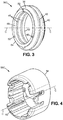
- the sealing element 36A-36F is a closed ring having a generally oval shape when it is stretched over the receiving sleeve.
- the sealing element 36A-36F comprises an external surface 38 provided with a front cylindrical bulging 40 and a rear cylindrical bulging 42 configured to interfere and to be compressed against the internal surface 44 of the corresponding cylindrical socket 14A-14F when the first and second connectors 10, 12 mate (see Fig. 5 ).
- the sealing element 36A-36F further comprises two annular ribs 46 protruding internally from an internal surface 48, thereby increasing friction between the sealing element 36A-36F and the corresponding cylindrical sleeve 24A-24F to reduce the risk that the sealing element 36A-36F moves axially along the corresponding cylindrical sleeve 24A-24F.
- the sealing element 36A-36F further comprises three protrusions 50 protruding from a rear axial surface 52 and an opposite front axial surface 54, thereby increasing friction between the sealing element 36A-36F and respectively the corresponding cylindrical sleeve 24A-24F and a corresponding retaining member (described later) to reduce the risk that the sealing element 36A-36F rotates around the corresponding axis AA-FF.
- the three protrusions 50 are evenly distributed on the axial surfaces 52, 54 around the respective axis AA-FF.
- the second casing 24 is provided with a first, a second, a third, a fourth, a fifth and a sixth retaining member 56A-56F ( Fig. 2 ).
- the retaining member 56A-56F surrounds the cylindrical sleeve 24A-24F and is configured as a stop member to retain the sealing element 36A-36F onto the cylindrical sleeve 24A-24F.
- the first, second, third, fourth, fifth and sixth retaining members 56A-56F are formed as separate and identical pieces.
- the retaining member 56A-56F comprises a cylindrical collar having a generally oval shape.
- the retaining member 56A-56F further comprises a rear axial surface 58 intended to be in contact with the front axial surface 54 of the corresponding sealing element 36A-36F when the retaining member 56A-56F and the corresponding sealing element 36A-36F are mounted on the corresponding cylindrical sleeve 24A-24F.
- the retaining member 56A-56F comprises two opposite and identical retaining lugs 60 protruding from an internal surface 62 and designed to cooperate with the corresponding cylindrical sleeve 24A-24F to secure the retaining member 56A-56F onto the corresponding cylindrical sleeve 24A-24F.
- Each retaining member 56A-56F is made from plastic material.
- each sealing element 36A-36F is sandwiched axially between the rear axial surface 58 of the corresponding retaining member 56A-56F and an external shoulder 64 provided on the corresponding cylindrical sleeve 24A-24F, thereby being secured onto the second connector 12.
- Each sealing element 36A-36F is also sandwiched radially between an external surface 66 of the corresponding cylindrical sleeve 24A-24F and the internal surface 44 of the corresponding cylindrical socket 14A-14F when the first and second connectors 10, 12 mate, thereby forming a radial compression seal with regard to the respective axis AA-FF.
- the sealing elements 36A-36F reduce the risk of water, moisture and/or dust contamination in the connectors.
- each sealing element 36A-36F seals the corresponding contact pair, each of these contact pairs being also sealed independently from the others.
- the connector assembly is simple to produce and has a reduced manufacturing cost.
- the electrical connector assembly is also provided with an electrical security system which guarantees that power flows through the connectors only in the case of correct and complete connectors mating.
- the electrical connector assembly may not comprise a mating assistance system, or may comprise a security system not cooperating with the mating assistance system.
- the second connector 12 comprises a slider 70 having a tubular shape along the mating axis XX.
- the slider 70 is slidingly mounted on the second casing 30 and comprises a longitudinal rack of teeth 72 extending parallel to the mating axis XX.
- the second connector 12 comprises a cam gear 74 mounted on an upper wall 76 of the second casing 30.
- the cam gear 74 is rotatably mounted with respect to the upper wall 76 around an axis YY perpendicular to the mating axis XX.
- the cam gear 74 comprises a guiding groove 78 for receiving and driving the guiding pin 22 of the first connector 10 (see Fig. 1 ).
- the guiding groove 78 has substantially a circular shape around an axis parallel to and offset from the axis YY.
- the guiding groove 78 comprises an entrance aperture 80 for receiving the guiding pin 22 of the first connector 10 and a side wall 82 delimitating the outer periphery of the guiding groove 78.
- the cam gear 74 comprises a gear section 84 with teeth extending circularly around the axis YY.
- the teeth of the gear section 84 are adapted to intermesh with the longitudinal rack of teeth 72 of the slider 70.
- the cam gear 74 further comprises a chamber 86 which radially opens on the periphery of the cam gear 74.
- the chamber 86 is delimitated on one side by a blocking wall 88 and on the other side by a wall 90 shared with the guiding groove 78.
- the cam gear 74 comprises a peripheral abutment surface 92 located between the gear section 84 and the chamber 86, opposite the guiding groove 78.
- the second casing 30 comprises a locking tooth 94 projecting from the upper wall 76 and having a front ramp 96 and a rear wall 98.
- the second connector 12 further comprises a CPA (Connector Position Assurance) element 100 mountable on the upper wall 76 of the second casing 30.
- CPA Connector Position Assurance
- the CPA element 100 comprises a cylindrical body 102 having a generally oval external shape to be received inside the sixth cylindrical sleeve 24F.
- a support part 104 extending forward from the cylindrical body 102, carries the sixth shunt contact 26F which is a shorting clip having a generally U-shape.
- the CPA element 100 comprises a linkage part 106 linking the cylindrical body 102 to a blocking arm 108 and a locking lever 110.
- the blocking arm 108 comprises a front face 112 and a lateral face 114, and is sized and shaped to be received in the chamber 86 of the cam gear 74.
- the locking lever 110 comprises a locking hole 116 delimitated by a front end wall 118 and a rear ramp 120.
- the locking hole 116 is sized and shaped to engage with the locking tooth 94 of the second casing 30.
- the locking lever 110 further comprises an actuation surface 122 adapted to be pushed, e.g. by a finger of a user, along a direction parallel to the axis YY, in order to release the locking lever 110 from engagement with the locking tooth 94.
- the CPA element 100 is formed as one piece, the cylindrical body 102, the support part 104, the linkage part 106, the blocking arm 108 and the locking lever 110 being integral with each other.
- the CPA element 100 is simple to produce and has a reduced manufacturing cost.
- a seventh sealing element 36G is provided on the CPA element 100 and surrounds the cylindrical body 102 to provide sealing between the CPA element 100 and the sixth cylindrical sleeve 24F as explained below.
- the seventh sealing element 36G is identical in shape and material to the other six sealing elements 36A-36F but has a slightly smaller size.
- the CPA element 100 is mounted on the upper wall 76.
- the CPA element 100 is slidingly movable with respect to the upper wall 76 along the axis FF parallel to the mating axis XX between a safety position and an active position in which the sixth shunt contact 26F carried by the CPA element 100 is connected to the corresponding sixth shunt contact of the first connector 10.
- the safety and active positions of the CPA element 100 are described in relation with the mating movement of the first and second connectors 10, 12.
- first and second connectors 10, 12 are unmated.
- the slider 70 is mounted on the second casing 30 such that the longitudinal rack of teeth 72 engages with the gear section 84 of the cam gear 74 and the entrance aperture 80 of the guiding groove 78 extends forwardly towards the mating interface of the second connector 12.
- the CPA element In this first initial configuration corresponding to an unassembled condition of the first and second connectors 10, 12, the CPA element is in its safety position ( Fig .7 ) with the rear face 112 of the blocking arm 108 abutting against the abutment surface 92 of the cam gear 74 and thereby preventing engagement of the locking lever 110 with the locking tooth 94 of the second casing 30.
- the first and second connectors 10, 12 are then aligned along the mating axis XX and brought closer to each other until the guiding pin 22 of the first connector 10 enters the guiding groove 78 of the cam gear 74 through the entrance aperture 80.
- the slider 70 is then moved forward along the mating direction, this causes the rack of teeth 72 to rotate the cam gear 74 via the intermesh of the teeth.
- the cam gear 74 rotates, it cams the guiding pin 22 to move along the guiding groove 78 so as to help move the second connector towards the first connector into final mated position.
- the rotation movement of the cam gear 74 stops when the guiding pin 22 meets the end of the guiding groove 78.
- the power switch of the battery is still open and power cannot flow through the other contact pairs.
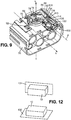
- the blocking arm 108 enters the chamber 86 and the locking lever 110 rides on the front ramp 96 of the locking tooth 94 until the locking tooth 94 engages the locking hole 116.
- the CPA element 100 finally reaches its active position ( Fig. 9 ) in which the sixth shunt contact 26F of the second connector 12 is connected to the corresponding contact of the first connector 10.
- the power switch of the battery is closed and power can flow through the other contact pairs.
- the CPA element 100 is further configured to block the rotation of the cam gear 74 in the direction of arrow Z', opposite to the direction of arrow Z, via the abutment of the lateral face 114 of the blocking arm 108 against the blocking wall 88 of the chamber 86, and thereby impeding the slider 70 from sliding rearward.
- the CPA element 100 further has the function of interlocking the first and second connectors 10, 12 to each other.
- the actuation surface 122 of the CPA element 100 is pushed along the axis YY so as to disengage the locking tooth 94 from the locking hole 116.
- the CPA element 100 is slid rearwardly, thereby releasing the cam gear 74 from the blocking arm 108 and at the same time disconnecting the sixth shunt contact pair.
- the connector assembly is in a configuration wherein, except for the sixth shunt contact pair, all the other contacts of the first connector 10 are still connected to the respective contacts of the second connector 12 but power cannot flow through them anymore.
- the slider 70 is then moved rearward and the first connector 10 is moved away from the second connector 12.
- the connector assembly and the CPA element are configured in such a way that the contact pairs can be disconnected only after the CPA element 100 has returned to its safety position, i.e. only after the power switch of the battery has been opened, i.e. only after power no longer flows through the connector assembly.
- the connector assembly is provided with an improved connection process in terms of safety, the electrical security system limiting the possibility of electrical arcing, thereby reducing the risk of injury to users and/or damage to the connectors and to the electrical appliances connected to the connector assembly.
- the CPA element 100 also serves as a visual checking means to determine the correct and complete mating of the first and second connectors 10, 12.
- the CPA element 100 being visible from the outside of the connector assembly, it can be visually distinguished if the CPA element 100 is in its active or safety position. With this function, a user can easily judge the state of the connection by simply looking at the CPA element 100.
- the seventh sealing element 36G surrounds the cylindrical body 102 of the CPA element 100 to seal the CPA element 100 in its active position ( Fig. 10 ) as well as in its safety position ( Fig. 11 ).
- the seventh sealing element 36G is sandwiched axially between an internal shoulder 124 provided on the corresponding cylindrical sleeve 24F which extends forward beyond the transversal wall 28 of the second casing 30, and an external shoulder 126 provided on the CPA element 100 at the junction between the cylindrical body 102 and the linkage part 106.
- the seventh sealing element 36G is also sandwiched radially between an external surface 128 of the cylindrical body 102 of the CPA element 100 and an internal surface 130 of the corresponding cylindrical sleeve 24F, thereby forming a radial compression seal with regard to the respective axis FF.
- the seventh sealing element 36G is sandwiched radially between the external surface 128 of the cylindrical body 102 of the CPA element 100 and the internal surface 130 of the corresponding cylindrical sleeve 24F, thereby forming a radial compression seal with regard to the respective axis FF.
- the seventh sealing element 36G participates in reducing the risk of water, moisture and/or dust contamination in the connectors by sealing the CPA element 100.
- the CPA element 100, the sixth shunt contact 26F and the sealing element 36G thus form a third electrical connector 132 ( Fig.8 ) which is integrated in and interacts with the second connector 12 and is configured to further connect with a first complementary connector.
- Connector assemblies having another number of contacts, the contacts being of the same or of different types are also part of the invention.
- connector assemblies are represented in relation to a special application (i.e. vehicles), but they could be used in other applications.
- the connector assembly comprises a first connector 10 and a second connector 12 intended to mate with the first one.
- the first connector 10 may for example be carried by a power supply, more precisely a battery 134, whereas the second connector 12 may be carried by a base 136 of an automotive vehicle
Landscapes
- Engineering & Computer Science (AREA)
- Power Engineering (AREA)
- Transportation (AREA)
- Mechanical Engineering (AREA)
- Details Of Connecting Devices For Male And Female Coupling (AREA)
- Connector Housings Or Holding Contact Members (AREA)
Claims (13)
- Elektrische Verbinderanordnung, die einen ersten Verbinder (10) mit einem ersten Gehäuse (16) und einem ersten Kontakt und einem zweiten Kontakt und einen zweiten Verbinder (12) mit einem zweiten Gehäuse (30) und einem ersten und einem zweiten Kontakt (26F) aufweist,
wobei der erste und der zweite Verbinder (10, 12) ausgebildet sind zum selektiven Zusammenfügen und Trennen entlang einer Verbindungsachse (XX) jeweils zwischen einem nicht-zusammengesetzten Zustand und einem zusammengesetzten Zustand, um die ersten Kontakte miteinander und die zweiten Kontakte miteinander elektrisch zu verbinden,
wobei der zweite Verbinder (12) ein CPA-Element (100) unterstützt, das einen der Kontakte (26F) trägt, und
wobei, in dem nicht-zusammengesetzten Zustand, das CPA-Element (100) an einer Anschlagfläche (92) anliegt, getragen durch einen des ersten und zweiten Verbinders (12), wodurch eine Bewegung des CPA-Elements (100) relativ zu dem zweiten Verbinder (12) zwischen einer Sicherheitsposition und einer aktiven Position verhindert wird, und wobei, in dem zusammengesetzten Zustand, das CPA-Element (100) nicht an die Anschlagfläche (92) anliegt, um relativ zu dem zweiten Verbinder (12) zwischen der Sicherheitsposition und der aktiven Position bewegbar zu sein, um den Kontakt (26F), der von dem CPA-Element (100) getragen wird, mit dem entsprechenden Kontakt des ersten Verbinders (10) zu verbinden, dadurch gekennzeichnet, dass
ein Dichtungssystem (36G) vorgesehen ist, um das CPA-Element (100) zu umgeben, um eine Abdichtung des CPA-Elements (100) in seiner aktiven Position sowie in seiner Sicherheitsposition vorzusehen, und
wobei das Dichtungssystem (36G) des CPA-Elements (100) zwischen einer Außenfläche (128) des CPA-Elements (100) und einer Innenfläche (130) eines Gehäuses (30) des zweiten Steckers vorgesehen ist, um dadurch eine radiale Komprimierungsdichtung zu bilden. - Elektrische Verbinderanordnung gemäß Anspruch 1, wobei die Anschlagfläche von dem zweiten Verbinder getragen wird.
- Elektrische Verbinderanordnung gemäß Anspruch 1, wobei das Dichtungssystem (36G) des CPA-Elements (100) eine radiale Komprimierungsdichtung in Bezug auf die Verbindungsachse (XX) aufweist.
- Elektrische Verbinderanordnung gemäß einem der Ansprüche 1 bis 3, wobei das Dichtungssystem (36G) des CPA-Elements (100) ein geschlossener Ring aus Silikonmaterial ist.
- Elektrische Verbinderanordnung gemäß einem der Ansprüche 1 bis 4, wobei der zweite Verbinder mit einem anderen Dichtungssystem (36F) vorgesehen ist, um eine Abdichtung des Kontakts (26F), der von dem CPA-Element (100) getragen wird, und des entsprechenden Kontakts des ersten Verbinders (10) vorzusehen, wenn der erste und der zweite Verbinder (10, 12) zusammengefügt sind.
- Elektrische Verbinderanordnung gemäß einem der Ansprüche 1 bis 5, wobei sich der von dem CPA-Element (100) getragene Kontakt (26F) von den anderen Kontakten des zweiten Verbinders (12) unterscheidet und sich der entsprechende Kontakt des ersten Verbinders (10) von den anderen Kontakten des ersten Verbinders (10) unterscheidet.
- Elektrische Verbinderanordnung gemäß einem der Ansprüche 1 bis 6, wobei durch das Zusammenfügen der ersten und zweiten Verbinder (10, 12) die Anschlagfläche (92) aus einem Eingriff mit dem CPA-Element (100) gelöst wird.
- Elektrische Verbinderanordnung gemäß einem der Ansprüche 1 bis 7, wobei die Anschlagfläche (92) durch ein Nockengetriebe (74) begrenzt ist, das rotierbar an einem Gehäuse (30) des zweiten Verbinders (12) gemäß einer Achse (YY) senkrecht zu der Verbindungsachse (XX) angebracht ist.
- Elektrische Verbinderanordnung gemäß einem der Ansprüche 1 bis 8, wobei das CPA-Element (100) einen Blockierarm (108) aufweist, der in der aktiven Position des CPA-Elements (100) den ersten und den zweiten Verbinder (10, 12) miteinander verriegelt.
- Elektrische Verbinderanordnung gemäß einem der Ansprüche 1 bis 9, wobei das CPA-Element (100) einen Verriegelungshebel (110) aufweist, der das CPA-Element (100) in seiner aktiven Position verriegelt.
- Elektrische Verbinderanordnung gemäß einem der Ansprüche 1 bis 10, wobei das CPA-Element (100) einstückig ausgebildet ist.
- Ein System, das aufweist:- eine Leistungsversorgung (134) mit zumindest zwei Leistungsausgängen;- eine Basis (136); und- eine Verbinderanordnung gemäß einem der Ansprüche 1 bis 11,wobei der erste Verbinder (10) an der Leistungsversorgung (134) angebracht ist, wobei seine Kontakte mit den Leistungsausgängen verbunden sind, und
wobei der zweite Verbinder (12) an der Basis (136) angebracht ist. - Ein Verbinder für eine Verbinderanordnung gemäß einem der Ansprüche 1 bis 11 und die Merkmale des zweiten Verbinders (12) der Anordnung aufweisend.
Applications Claiming Priority (2)
| Application Number | Priority Date | Filing Date | Title |
|---|---|---|---|
| IB2011001455 | 2011-05-17 | ||
| PCT/EP2012/058943 WO2012156373A1 (en) | 2011-05-17 | 2012-05-14 | Electrical connector assembly with a cpa element |
Publications (2)
| Publication Number | Publication Date |
|---|---|
| EP2710690A1 EP2710690A1 (de) | 2014-03-26 |
| EP2710690B1 true EP2710690B1 (de) | 2018-02-28 |
Family
ID=46085963
Family Applications (1)
| Application Number | Title | Priority Date | Filing Date |
|---|---|---|---|
| EP12721516.8A Active EP2710690B1 (de) | 2011-05-17 | 2012-05-14 | ELEkTRISCHE VERBINDUNGSANORDNUNG MIT LAGESICHERUNGSELEMENT (CPA) |
Country Status (3)
| Country | Link |
|---|---|
| US (1) | US9054459B2 (de) |
| EP (1) | EP2710690B1 (de) |
| WO (1) | WO2012156373A1 (de) |
Families Citing this family (8)
| Publication number | Priority date | Publication date | Assignee | Title |
|---|---|---|---|---|
| US9748695B2 (en) * | 2014-04-30 | 2017-08-29 | Ford Global Technologies, Llc | High voltage connector assembly |
| US9653846B1 (en) * | 2016-06-09 | 2017-05-16 | Delphi Technologies, Inc. | Connector assembly with positional assurance |
| US10148034B2 (en) * | 2016-08-01 | 2018-12-04 | Te Connectivity Corporation | Arcless power connector |
| JP6654685B2 (ja) * | 2018-01-10 | 2020-02-26 | デルファイ・テクノロジーズ・エルエルシー | 可変軸方向補助を有するコネクタ組立体 |
| US12142876B2 (en) * | 2019-07-16 | 2024-11-12 | Tyco Electronics Japan G.K. | Connector |
| JP7386523B2 (ja) * | 2020-02-06 | 2023-11-27 | 日本圧着端子製造株式会社 | コネクタロック機構 |
| US12294184B2 (en) * | 2021-09-21 | 2025-05-06 | Aptiv Technologies AG | Legible confirmation of mated connection system |
| US12126116B2 (en) * | 2022-07-01 | 2024-10-22 | Aptiv Technologies AG | Vehicle electrical distribution center with gear driven mating assist system |
Citations (1)
| Publication number | Priority date | Publication date | Assignee | Title |
|---|---|---|---|---|
| WO2010026449A1 (en) * | 2008-09-04 | 2010-03-11 | Fci | Sealable squib connector |
Family Cites Families (15)
| Publication number | Priority date | Publication date | Assignee | Title |
|---|---|---|---|---|
| US4634204A (en) * | 1985-12-24 | 1987-01-06 | General Motors Corporation | Electrical connector with connector position assurance/assist device |
| US6217388B1 (en) * | 2000-02-04 | 2001-04-17 | Delphi Technologies, Inc. | Low profile SIR connector and terminal |
| US6896538B2 (en) | 2002-10-31 | 2005-05-24 | Tyco Electronics Corporation | Self-cleaning CPA device for high-debris applications |
| JP3902605B2 (ja) * | 2004-03-31 | 2007-04-11 | 矢崎総業株式会社 | レバー嵌合式コネクタ |
| DE102004057093B3 (de) * | 2004-11-25 | 2006-05-24 | Yazaki Europe Ltd., Hemel Hempstead | Steckverbindung |
| US7744390B2 (en) | 2005-07-28 | 2010-06-29 | Fci Americas Technology, Inc. | Electrical connector assembly with connection assist |
| JP2007149420A (ja) * | 2005-11-25 | 2007-06-14 | Yazaki Corp | レバー嵌合式コネクタ |
| US7351089B2 (en) * | 2006-04-28 | 2008-04-01 | Delphi Technologies, Inc. | Electrical connector having a CPA plug |
| DE102007005198A1 (de) | 2007-01-29 | 2008-08-07 | Yazaki Europe Ltd., Hemel Hempstead | Steckverbindung mit Schieber |
| EP2153496B1 (de) | 2007-05-24 | 2017-08-02 | Delphi International Operations Luxembourg S.à r.l. | Einrichtung zur kupplungserkennung und damit versehene verbinder und verbinderanordnung |
| DE102007026261A1 (de) | 2007-06-05 | 2008-12-11 | Kostal Kontakt Systeme Gmbh | Elektrischer Steckverbinder |
| JP5182941B2 (ja) * | 2008-11-26 | 2013-04-17 | 矢崎総業株式会社 | 複合コネクタ |
| DE102009053674B4 (de) * | 2009-11-19 | 2011-09-01 | Yazaki Europe Ltd. | Steckverbinder mit Sekundärsteckverbinder |
| CN102834984B (zh) * | 2010-04-09 | 2015-09-30 | 富加宜汽车控股公司 | 电连接器系统 |
| US8628344B2 (en) * | 2011-10-12 | 2014-01-14 | Yazaki North America, Inc. | Connector and terminal positioning mechanism |
-
2012
- 2012-05-14 WO PCT/EP2012/058943 patent/WO2012156373A1/en not_active Ceased
- 2012-05-14 EP EP12721516.8A patent/EP2710690B1/de active Active
- 2012-05-14 US US14/114,787 patent/US9054459B2/en active Active
Patent Citations (1)
| Publication number | Priority date | Publication date | Assignee | Title |
|---|---|---|---|---|
| WO2010026449A1 (en) * | 2008-09-04 | 2010-03-11 | Fci | Sealable squib connector |
Also Published As
| Publication number | Publication date |
|---|---|
| WO2012156373A1 (en) | 2012-11-22 |
| US9054459B2 (en) | 2015-06-09 |
| US20140065857A1 (en) | 2014-03-06 |
| EP2710690A1 (de) | 2014-03-26 |
Similar Documents
| Publication | Publication Date | Title |
|---|---|---|
| EP2710690B1 (de) | ELEkTRISCHE VERBINDUNGSANORDNUNG MIT LAGESICHERUNGSELEMENT (CPA) | |
| EP2795740B1 (de) | Verbesserte elektrische steckverbinderanordnung | |
| US8192212B2 (en) | Electrical connector system with temporarily blocking during unmating of two connectors | |
| US6336822B1 (en) | Handle operated power connector | |
| JP5500680B2 (ja) | レバー式電気コネクタ | |
| US20130095692A1 (en) | Connector and terminal positioning mechanism | |
| US20120231644A1 (en) | Vehicle charge cable socket connector | |
| EP2761703B1 (de) | Verbinderbaugruppe | |
| US12057658B2 (en) | Electrical contact device with interlock | |
| EP1024559A2 (de) | Hebelbetätigbarer Leistungsverbinder | |
| EP3200287B1 (de) | Verbinder | |
| US5913691A (en) | Dual power/control connector | |
| US12176652B2 (en) | Connector device | |
| WO2013092174A1 (en) | Electrical connector with a lever and a connector position assurance (cpa) element | |
| WO2010015889A1 (en) | Electrical connector assembly, an electrical device comprising the same and a method for mating the same | |
| WO2010015890A1 (en) | Electrical connector assembly | |
| CA2933388A1 (en) | Plug connection | |
| CN111971858B (zh) | 电插头插座装置 | |
| WO2012156358A1 (en) | Electrical connector assembly with sealing systems | |
| CN203312582U (zh) | 插座以及使用该插座的电连接器组件 | |
| CN110829130B (zh) | 电源转接组件 | |
| JP2015018641A (ja) | コネクタ及びコネクタ装置 | |
| WO2010015888A1 (en) | Electrical connector assembly, an electrical device comprising the same and a method for unmating the same | |
| CN103219618B (zh) | 一种插座以及使用该插座的电连接器组件 | |
| JP2017220297A (ja) | コネクタ |
Legal Events
| Date | Code | Title | Description |
|---|---|---|---|
| PUAI | Public reference made under article 153(3) epc to a published international application that has entered the european phase |
Free format text: ORIGINAL CODE: 0009012 |
|
| 17P | Request for examination filed |
Effective date: 20131217 |
|
| AK | Designated contracting states |
Kind code of ref document: A1 Designated state(s): AL AT BE BG CH CY CZ DE DK EE ES FI FR GB GR HR HU IE IS IT LI LT LU LV MC MK MT NL NO PL PT RO RS SE SI SK SM TR |
|
| DAX | Request for extension of the european patent (deleted) | ||
| 17Q | First examination report despatched |
Effective date: 20160425 |
|
| REG | Reference to a national code |
Ref country code: DE Ref legal event code: R079 Ref document number: 602012043346 Country of ref document: DE Free format text: PREVIOUS MAIN CLASS: H01R0013641000 Ipc: H01R0013642000 |
|
| RIC1 | Information provided on ipc code assigned before grant |
Ipc: H01R 13/629 20060101ALI20170628BHEP Ipc: H01R 13/642 20060101AFI20170628BHEP Ipc: H01R 13/641 20060101ALI20170628BHEP Ipc: H01R 13/52 20060101ALI20170628BHEP Ipc: H01R 13/70 20060101ALI20170628BHEP Ipc: B60L 11/18 20060101ALI20170628BHEP |
|
| GRAP | Despatch of communication of intention to grant a patent |
Free format text: ORIGINAL CODE: EPIDOSNIGR1 |
|
| INTG | Intention to grant announced |
Effective date: 20170920 |
|
| GRAS | Grant fee paid |
Free format text: ORIGINAL CODE: EPIDOSNIGR3 |
|
| GRAA | (expected) grant |
Free format text: ORIGINAL CODE: 0009210 |
|
| AK | Designated contracting states |
Kind code of ref document: B1 Designated state(s): AL AT BE BG CH CY CZ DE DK EE ES FI FR GB GR HR HU IE IS IT LI LT LU LV MC MK MT NL NO PL PT RO RS SE SI SK SM TR |
|
| REG | Reference to a national code |
Ref country code: GB Ref legal event code: FG4D Ref country code: CH Ref legal event code: EP |
|
| REG | Reference to a national code |
Ref country code: AT Ref legal event code: REF Ref document number: 975108 Country of ref document: AT Kind code of ref document: T Effective date: 20180315 |
|
| REG | Reference to a national code |
Ref country code: IE Ref legal event code: FG4D |
|
| REG | Reference to a national code |
Ref country code: DE Ref legal event code: R096 Ref document number: 602012043346 Country of ref document: DE |
|
| REG | Reference to a national code |
Ref country code: FR Ref legal event code: PLFP Year of fee payment: 7 |
|
| REG | Reference to a national code |
Ref country code: NL Ref legal event code: MP Effective date: 20180228 |
|
| REG | Reference to a national code |
Ref country code: LT Ref legal event code: MG4D |
|
| REG | Reference to a national code |
Ref country code: AT Ref legal event code: MK05 Ref document number: 975108 Country of ref document: AT Kind code of ref document: T Effective date: 20180228 |
|
| PG25 | Lapsed in a contracting state [announced via postgrant information from national office to epo] |
Ref country code: FI Free format text: LAPSE BECAUSE OF FAILURE TO SUBMIT A TRANSLATION OF THE DESCRIPTION OR TO PAY THE FEE WITHIN THE PRESCRIBED TIME-LIMIT Effective date: 20180228 Ref country code: NO Free format text: LAPSE BECAUSE OF FAILURE TO SUBMIT A TRANSLATION OF THE DESCRIPTION OR TO PAY THE FEE WITHIN THE PRESCRIBED TIME-LIMIT Effective date: 20180528 Ref country code: LT Free format text: LAPSE BECAUSE OF FAILURE TO SUBMIT A TRANSLATION OF THE DESCRIPTION OR TO PAY THE FEE WITHIN THE PRESCRIBED TIME-LIMIT Effective date: 20180228 Ref country code: CY Free format text: LAPSE BECAUSE OF FAILURE TO SUBMIT A TRANSLATION OF THE DESCRIPTION OR TO PAY THE FEE WITHIN THE PRESCRIBED TIME-LIMIT Effective date: 20180228 Ref country code: HR Free format text: LAPSE BECAUSE OF FAILURE TO SUBMIT A TRANSLATION OF THE DESCRIPTION OR TO PAY THE FEE WITHIN THE PRESCRIBED TIME-LIMIT Effective date: 20180228 Ref country code: NL Free format text: LAPSE BECAUSE OF FAILURE TO SUBMIT A TRANSLATION OF THE DESCRIPTION OR TO PAY THE FEE WITHIN THE PRESCRIBED TIME-LIMIT Effective date: 20180228 Ref country code: ES Free format text: LAPSE BECAUSE OF FAILURE TO SUBMIT A TRANSLATION OF THE DESCRIPTION OR TO PAY THE FEE WITHIN THE PRESCRIBED TIME-LIMIT Effective date: 20180228 |
|
| PG25 | Lapsed in a contracting state [announced via postgrant information from national office to epo] |
Ref country code: AT Free format text: LAPSE BECAUSE OF FAILURE TO SUBMIT A TRANSLATION OF THE DESCRIPTION OR TO PAY THE FEE WITHIN THE PRESCRIBED TIME-LIMIT Effective date: 20180228 Ref country code: SE Free format text: LAPSE BECAUSE OF FAILURE TO SUBMIT A TRANSLATION OF THE DESCRIPTION OR TO PAY THE FEE WITHIN THE PRESCRIBED TIME-LIMIT Effective date: 20180228 Ref country code: LV Free format text: LAPSE BECAUSE OF FAILURE TO SUBMIT A TRANSLATION OF THE DESCRIPTION OR TO PAY THE FEE WITHIN THE PRESCRIBED TIME-LIMIT Effective date: 20180228 Ref country code: BG Free format text: LAPSE BECAUSE OF FAILURE TO SUBMIT A TRANSLATION OF THE DESCRIPTION OR TO PAY THE FEE WITHIN THE PRESCRIBED TIME-LIMIT Effective date: 20180528 Ref country code: RS Free format text: LAPSE BECAUSE OF FAILURE TO SUBMIT A TRANSLATION OF THE DESCRIPTION OR TO PAY THE FEE WITHIN THE PRESCRIBED TIME-LIMIT Effective date: 20180228 Ref country code: GR Free format text: LAPSE BECAUSE OF FAILURE TO SUBMIT A TRANSLATION OF THE DESCRIPTION OR TO PAY THE FEE WITHIN THE PRESCRIBED TIME-LIMIT Effective date: 20180529 |
|
| PG25 | Lapsed in a contracting state [announced via postgrant information from national office to epo] |
Ref country code: RO Free format text: LAPSE BECAUSE OF FAILURE TO SUBMIT A TRANSLATION OF THE DESCRIPTION OR TO PAY THE FEE WITHIN THE PRESCRIBED TIME-LIMIT Effective date: 20180228 Ref country code: IT Free format text: LAPSE BECAUSE OF FAILURE TO SUBMIT A TRANSLATION OF THE DESCRIPTION OR TO PAY THE FEE WITHIN THE PRESCRIBED TIME-LIMIT Effective date: 20180228 Ref country code: EE Free format text: LAPSE BECAUSE OF FAILURE TO SUBMIT A TRANSLATION OF THE DESCRIPTION OR TO PAY THE FEE WITHIN THE PRESCRIBED TIME-LIMIT Effective date: 20180228 Ref country code: PL Free format text: LAPSE BECAUSE OF FAILURE TO SUBMIT A TRANSLATION OF THE DESCRIPTION OR TO PAY THE FEE WITHIN THE PRESCRIBED TIME-LIMIT Effective date: 20180228 Ref country code: AL Free format text: LAPSE BECAUSE OF FAILURE TO SUBMIT A TRANSLATION OF THE DESCRIPTION OR TO PAY THE FEE WITHIN THE PRESCRIBED TIME-LIMIT Effective date: 20180228 |
|
| REG | Reference to a national code |
Ref country code: DE Ref legal event code: R097 Ref document number: 602012043346 Country of ref document: DE |
|
| PG25 | Lapsed in a contracting state [announced via postgrant information from national office to epo] |
Ref country code: SM Free format text: LAPSE BECAUSE OF FAILURE TO SUBMIT A TRANSLATION OF THE DESCRIPTION OR TO PAY THE FEE WITHIN THE PRESCRIBED TIME-LIMIT Effective date: 20180228 Ref country code: DK Free format text: LAPSE BECAUSE OF FAILURE TO SUBMIT A TRANSLATION OF THE DESCRIPTION OR TO PAY THE FEE WITHIN THE PRESCRIBED TIME-LIMIT Effective date: 20180228 Ref country code: SK Free format text: LAPSE BECAUSE OF FAILURE TO SUBMIT A TRANSLATION OF THE DESCRIPTION OR TO PAY THE FEE WITHIN THE PRESCRIBED TIME-LIMIT Effective date: 20180228 Ref country code: CZ Free format text: LAPSE BECAUSE OF FAILURE TO SUBMIT A TRANSLATION OF THE DESCRIPTION OR TO PAY THE FEE WITHIN THE PRESCRIBED TIME-LIMIT Effective date: 20180228 |
|
| REG | Reference to a national code |
Ref country code: DE Ref legal event code: R081 Ref document number: 602012043346 Country of ref document: DE Owner name: APTIV TECHNOLOGIES LIMITED, BB Free format text: FORMER OWNER: DELPHI INTERNATIONAL OPERATIONS LUXEMBOURG S.A R.L., BASCHARAGE, LU |
|
| REG | Reference to a national code |
Ref country code: CH Ref legal event code: PL |
|
| PLBE | No opposition filed within time limit |
Free format text: ORIGINAL CODE: 0009261 |
|
| STAA | Information on the status of an ep patent application or granted ep patent |
Free format text: STATUS: NO OPPOSITION FILED WITHIN TIME LIMIT |
|
| REG | Reference to a national code |
Ref country code: GB Ref legal event code: 732E Free format text: REGISTERED BETWEEN 20181213 AND 20181219 |
|
| REG | Reference to a national code |
Ref country code: BE Ref legal event code: MM Effective date: 20180531 |
|
| PG25 | Lapsed in a contracting state [announced via postgrant information from national office to epo] |
Ref country code: MC Free format text: LAPSE BECAUSE OF FAILURE TO SUBMIT A TRANSLATION OF THE DESCRIPTION OR TO PAY THE FEE WITHIN THE PRESCRIBED TIME-LIMIT Effective date: 20180228 |
|
| 26N | No opposition filed |
Effective date: 20181129 |
|
| REG | Reference to a national code |
Ref country code: IE Ref legal event code: MM4A |
|
| PG25 | Lapsed in a contracting state [announced via postgrant information from national office to epo] |
Ref country code: SI Free format text: LAPSE BECAUSE OF FAILURE TO SUBMIT A TRANSLATION OF THE DESCRIPTION OR TO PAY THE FEE WITHIN THE PRESCRIBED TIME-LIMIT Effective date: 20180228 Ref country code: LI Free format text: LAPSE BECAUSE OF NON-PAYMENT OF DUE FEES Effective date: 20180531 Ref country code: CH Free format text: LAPSE BECAUSE OF NON-PAYMENT OF DUE FEES Effective date: 20180531 |
|
| PG25 | Lapsed in a contracting state [announced via postgrant information from national office to epo] |
Ref country code: LU Free format text: LAPSE BECAUSE OF NON-PAYMENT OF DUE FEES Effective date: 20180514 |
|
| PG25 | Lapsed in a contracting state [announced via postgrant information from national office to epo] |
Ref country code: IE Free format text: LAPSE BECAUSE OF NON-PAYMENT OF DUE FEES Effective date: 20180514 |
|
| PG25 | Lapsed in a contracting state [announced via postgrant information from national office to epo] |
Ref country code: BE Free format text: LAPSE BECAUSE OF NON-PAYMENT OF DUE FEES Effective date: 20180531 |
|
| PG25 | Lapsed in a contracting state [announced via postgrant information from national office to epo] |
Ref country code: MT Free format text: LAPSE BECAUSE OF NON-PAYMENT OF DUE FEES Effective date: 20180514 |
|
| PG25 | Lapsed in a contracting state [announced via postgrant information from national office to epo] |
Ref country code: TR Free format text: LAPSE BECAUSE OF FAILURE TO SUBMIT A TRANSLATION OF THE DESCRIPTION OR TO PAY THE FEE WITHIN THE PRESCRIBED TIME-LIMIT Effective date: 20180228 |
|
| PG25 | Lapsed in a contracting state [announced via postgrant information from national office to epo] |
Ref country code: HU Free format text: LAPSE BECAUSE OF FAILURE TO SUBMIT A TRANSLATION OF THE DESCRIPTION OR TO PAY THE FEE WITHIN THE PRESCRIBED TIME-LIMIT; INVALID AB INITIO Effective date: 20120514 Ref country code: PT Free format text: LAPSE BECAUSE OF FAILURE TO SUBMIT A TRANSLATION OF THE DESCRIPTION OR TO PAY THE FEE WITHIN THE PRESCRIBED TIME-LIMIT Effective date: 20180228 |
|
| PG25 | Lapsed in a contracting state [announced via postgrant information from national office to epo] |
Ref country code: MK Free format text: LAPSE BECAUSE OF NON-PAYMENT OF DUE FEES Effective date: 20180228 |
|
| PG25 | Lapsed in a contracting state [announced via postgrant information from national office to epo] |
Ref country code: IS Free format text: LAPSE BECAUSE OF FAILURE TO SUBMIT A TRANSLATION OF THE DESCRIPTION OR TO PAY THE FEE WITHIN THE PRESCRIBED TIME-LIMIT Effective date: 20180628 |
|
| P01 | Opt-out of the competence of the unified patent court (upc) registered |
Effective date: 20230425 |
|
| REG | Reference to a national code |
Ref country code: DE Ref legal event code: R081 Ref document number: 602012043346 Country of ref document: DE Owner name: APTIV TECHNOLOGIES AG, CH Free format text: FORMER OWNER: APTIV TECHNOLOGIES LIMITED, ST. MICHAEL, BB |
|
| PGFP | Annual fee paid to national office [announced via postgrant information from national office to epo] |
Ref country code: DE Payment date: 20250422 Year of fee payment: 14 |
|
| PGFP | Annual fee paid to national office [announced via postgrant information from national office to epo] |
Ref country code: GB Payment date: 20250410 Year of fee payment: 14 |
|
| PGFP | Annual fee paid to national office [announced via postgrant information from national office to epo] |
Ref country code: FR Payment date: 20250404 Year of fee payment: 14 |