EP2707296B1 - Einrichtung zum öffnen und entleeren von gefüllten steckkapseln - Google Patents
Einrichtung zum öffnen und entleeren von gefüllten steckkapseln Download PDFInfo
- Publication number
- EP2707296B1 EP2707296B1 EP12720803.1A EP12720803A EP2707296B1 EP 2707296 B1 EP2707296 B1 EP 2707296B1 EP 12720803 A EP12720803 A EP 12720803A EP 2707296 B1 EP2707296 B1 EP 2707296B1
- Authority
- EP
- European Patent Office
- Prior art keywords
- capsule
- clamping
- track
- capsules
- sorting
- Prior art date
- Legal status (The legal status is an assumption and is not a legal conclusion. Google has not performed a legal analysis and makes no representation as to the accuracy of the status listed.)
- Not-in-force
Links
Images

Classifications
-
- B—PERFORMING OPERATIONS; TRANSPORTING
- B65—CONVEYING; PACKING; STORING; HANDLING THIN OR FILAMENTARY MATERIAL
- B65B—MACHINES, APPARATUS OR DEVICES FOR, OR METHODS OF, PACKAGING ARTICLES OR MATERIALS; UNPACKING
- B65B69/00—Unpacking of articles or materials, not otherwise provided for
-
- A—HUMAN NECESSITIES
- A61—MEDICAL OR VETERINARY SCIENCE; HYGIENE
- A61J—CONTAINERS SPECIALLY ADAPTED FOR MEDICAL OR PHARMACEUTICAL PURPOSES; DEVICES OR METHODS SPECIALLY ADAPTED FOR BRINGING PHARMACEUTICAL PRODUCTS INTO PARTICULAR PHYSICAL OR ADMINISTERING FORMS; DEVICES FOR ADMINISTERING FOOD OR MEDICINES ORALLY; BABY COMFORTERS; DEVICES FOR RECEIVING SPITTLE
- A61J3/00—Devices or methods specially adapted for bringing pharmaceutical products into particular physical or administering forms
- A61J3/07—Devices or methods specially adapted for bringing pharmaceutical products into particular physical or administering forms into the form of capsules or similar small containers for oral use
- A61J3/071—Devices or methods specially adapted for bringing pharmaceutical products into particular physical or administering forms into the form of capsules or similar small containers for oral use into the form of telescopically engaged two-piece capsules
- A61J3/074—Filling capsules; Related operations
-
- B—PERFORMING OPERATIONS; TRANSPORTING
- B65—CONVEYING; PACKING; STORING; HANDLING THIN OR FILAMENTARY MATERIAL
- B65B—MACHINES, APPARATUS OR DEVICES FOR, OR METHODS OF, PACKAGING ARTICLES OR MATERIALS; UNPACKING
- B65B69/00—Unpacking of articles or materials, not otherwise provided for
- B65B69/005—Unpacking of articles or materials, not otherwise provided for by expelling contents, e.g. by squeezing the container
Definitions
- the invention relates to a device for opening and emptying filled plug capsules.
- capsules for example, in the field of pharmacy and dietary supplements so-called capsules are used, in which a drug preparation is included, and which are intended for swallowing by the user.
- Such capsules consist for example of hard gelatin or of HPMC (hydroxypropylmethylcellulose) or the like, wherein the capsule material dissolves after ingestion and releases the drug preparation.
- HPMC hydroxypropylmethylcellulose
- the plug capsules are formed from a lower capsule part and a capsule upper part, wherein first the capsule lower part is filled, and in which case then a capsule upper part is attached to the filled capsule lower part.
- the plug connection is sufficiently strong so that both parts do not unintentionally separate from each other.
- the AT 397 764 B discloses for this purpose a machine for automated opening and emptying of gelatin capsules, as used in the pharmaceutical industry.
- the capsules are pushed by means of a guide slide in a separating block of two rubber sleeves. When the two rubber sleeves are pulled apart, the capsule parts held therein by friction are separated from one another.
- the invention has for its object to provide a means for opening and emptying filled plug capsules, with an economical and material-saving recovery of the contents of filled and sealed capsules is possible.
- the device according to the invention comprises a separating block for separating the lower part of the capsule and the upper part of the capsule and a guide slide for pushing in a single plug-in capsule into the separating block in an indenting direction.
- the separating block has a first clamping track for the capsule lower part and a second clamping track for the capsule upper part, wherein the clamping tracks are configured such that they each have a feed direction in which the capsule lower part or the capsule upper part can be moved by means of the guide slide and perpendicular thereto is held clamped.
- the two clamping tracks are inclined relative to one another in such a way that their respective directions of advance with respect to the direction of insertion of the guide slide run apart in an opening angle.
- the lower part of the capsule and the upper part of the capsule are forced into paths diverging from one another while they follow the advancement of the guide slide.
- the divergent webs cause the capsule lower part and the capsule upper part to move away from each other, starting from their closed insertion position, and finally to be completely separated from one another.
- the valuable contents can be removed and fed to another filling or other post-processing.
- the opening of the plug capsule is carried out with only a small load of the capsule material, so that capsule damage and an associated contamination of the contents are reliably avoided. High clock rates are possible.
- the result is a compact design that allows a list of the device according to the invention in existing GMP (Good Manufacturing Practice) rooms, for example, in those rooms in which the capsule filling and closing machine is located.
- GMP Good Manufacturing Practice
- the clamping tracks each have a pair of at least approximately parallel and mutually facing clamping edges, wherein the pair of parallel clamping edges of the first clamping track in the opening angle to the pair of parallel clamping edges of the second clamping track.
- the pairs formed by clamping edges on pairs of clamping plates.
- the arrangement is structurally simple in construction and reliable in terms of their clamping guiding effect.
- the between the clamping edges clamped capsule parts can be moved with little effort and without excessive stress on the capsule material in the respective feed direction.
- the clamping edges prevent a sliding movement of the respective capsule part held therein perpendicular to the feed direction, so that the plug capsule is reliably opened along the feed path of the guide slide.
- the separation block is preceded by a sorting device for oriented alignment and supply of a single plug capsule to the separation block, wherein the first clamping track is adapted to the diameter of the capsule lower part and the second clamping track to the diameter of the capsule shell.
- the sorter ensures that the initially unoriented supplied plug capsules are oriented so that regardless of their feed orientation always the capsule lower part of the associated first clamping track and always a capsule top of the associated second clamping track are supplied.
- the individual vote on the capsule upper and lower capsule parts which differ from one another in diameter, enables a precisely predefinable clamping effect on the capsule lower part and on the capsule upper part, without one of them being overloaded or experiencing too little clamping action.
- the design of the separation block on the diameter differences of the plug capsules allows a safe and non-destructive capsule opening.
- the clean longitudinal guide and transversely thereto the clamping effect is achieved in that the distance between the clamping edges of the first clamping track is smaller by a first clamping dimension than the diameter of the capsule lower part, and that the distance between the clamping edges of the second clamping track is smaller than the diameter of the capsule upper part by a second clamping dimension.
- the sorting device advantageously has a sorting block with an ejection channel for receiving unoriented supplied plug capsules and a sorting slide for orienting pivoting in the ejection channel and for discharging the oriented pivoted plug capsules from the ejection channel.
- the effect is made use of that the closed capsules have their maximum diameter and also their maximum stiffness in the area of the upper part calotte.
- the plug capsule is held in the discharge channel with little clamping effect, the location of the clamping action predetermining an eccentric pivot axis.
- the laterally zoomed and centrally hit on the plug sorter initially performs a pivoting movement of the plugged in such a way that their thinner capsule base points in the ejection direction of the sorter forward.
- the plug capsule After pivoting, the plug capsule is ejected regardless of their starting position with the thinner capsule lower part facing forward and fed to the separation block in the correct position, whereby a clear assignment of capsule shell and capsule base is ensured for each clamping track.
- the clamping tracks and the sorting block can be formed as so-called format parts, so that all other common and different plug caps sizes can be processed with otherwise constant construction of the device according to the invention.
- the sorting device has a capsule supply for the sorting block, which exerts a lifting movement.
- the lifting movement of the guide slide is coupled to the lifting movement of the capsule supply, which can advantageously be erected by a fixed attachment of the guide slide on the capsule supply. Without additional control effort it is ensured that the processes of the Capsule orientation and the capsule opening run synchronously. This contributes to the reliability at high clock rate.
- the opening angle lies in a range of from 10 ° to 50 ° inclusive and preferably in a range from 20 ° to 40 ° inclusive, and in particular at least approximately 30 °.
- a separating device for separating the opened capsule bottoms and capsule tops from the capsule contents is arranged below the separating block.
- the separating device is formed by a vibrating screen with a arranged below the vibrating screen collecting container for the capsule contents.
- the vibrating sieve retains the opened capsules while the contents of the capsule fall through the sieve meshes into the receptacle. With sufficient tightness, it is also possible to retain fragments of unwanted capsule parts, so that a high degree of purity of the recovered capsule contents is ensured.
- the vibrating screen also ensures, as a result of its shaking motion, that all of the capsule contents are removed from the shaken capsule tops and capsule bottoms and fed through the sieve to the collection bin.
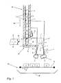
- Fig. 1 shows a schematic, partially sectioned side view of an embodiment of the device according to the invention for opening and emptying of filled capsules 1.
- Each individual plug capsule 1 is formed from a capsule lower part 2 and a capsule upper part 3 plugged thereon.
- the plug capsules 1 and their capsule parts 2 and capsule tops 3 are made of hard gelatin, HPMC or the like and contain an active substance preparation, which is in particular in the form of a fine-grained powder.
- the device according to the invention shown is intended to recover the capsule contents in the event of improper filling of the capsules 1 or for other reasons.
- the device comprises a capsule feed 23, a sorting device 19, a separating block 4 and a separating device 24.
- the sorter 19 By means of the capsule feed 23 in the form of a vertical channel filled plug capsules 1 from a storage container, not shown, the sorter 19 are supplied.
- the vertical channel of the capsule feed 23 has a cross section which is slightly larger than the diameter of the plug capsules 1, so that the plug capsules 1 can fall vertically aligned in a row over the channel into the sorting device 19.
- the sockets 1 lie in the Capsule feed 23 so unoriented that randomly either a lower capsule part 2 or a capsule upper part 3 comes to rest facing down.
- the sorting device 19 comprises a sorting block 20 with a horizontally arranged and upwardly open discharge channel 21 and a horizontally according to a double arrow 29 oscillating movable sorting slide 22 with a discharge channel 21 facing the top 30th
- the separating block 4 is provided for separating the capsule lower part 2 and capsule upper part 3 starting from their assembled state and comprises a first clamping track 7 for a single capsule lower part 2 and a second clamping track 8 for a single capsule upper part 3.
- the first clamping track 7 has a feed direction 9, while the second clamping track 8 has a feed direction 10.
- an acting on a single plug capsule 1 guide slide 5 is provided, which is rigidly fixed in the embodiment shown on the capsule supply 23 and together with this according to a double arrow 28 oscillating in the vertical direction is movable up and down.
- the lifting movement of the guide slide 5 is coupled to the lifting movement of the capsule supply 23 according to the double arrow 28.
- it can also be dispensed with a rigid connection between the two modules, in which case both strokes are driven separately and coordinated or synchronized by means of a suitable control device.
- the guide slide 5 moves in a Eindschreibraum 6 and presses a single plug capsule 1 in the separation block 4.
- the two clamping tracks 7, 8 are inclined relative to each other, that their feed directions 9, 10 with respect to the vertical indentation 6 of the guide slide. 5 diverge in an opening angle ⁇ .
- the Aperture angle ⁇ is suitably in a range of from 10 ° to 50 ° inclusive and preferably in a range of 20 ° to 40 ° inclusive. In the illustrated embodiment, the opening angle ⁇ is at least approximately 30 °.
- the separating device 24 is arranged for separating the opened lower parts 2 and capsule tops 3 of their capsule contents.
- the separating device 24 is formed by a vibrating screen 25 and by a below the vibrating screen 25 arranged collecting container 26 for the capsule contents.
- the vibrating screen 25 is horizontally oscillating by means of a non-darg Congressen drive according to a double arrow 27 movable. Additionally or alternatively, a vertical oscillation movement may be provided.
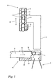
- Fig. 2 shows in a schematic cross-sectional view of the sorting block 20 after Fig. 1 with a single upright in the discharge channel 21 on the channel bottom 35 upstanding plug capsule 1.
- the capsule base 2 is above, while the capsule shell 3 is below.
- the capsule upper part 3 has a diameter D o , which is larger by such a measure than a diameter D u of the capsule lower part 2 that the capsule lower part 2 can be inserted by clamping into the capsule upper part 3.
- the upwardly open discharge channel 21 is bounded laterally by mutually parallel channel walls 33, wherein their distance from each other is slightly smaller than the diameter D o of the capsule shell 3, but larger than the diameter D u of the capsule lower part 2.
- a horizontal pivot axis 34 is formed at the location of the maximum surface pressure, namely in the transition region from the cylindrical section to the spherical cap section of the capsule upper part 3.
- Fig. 1 and 2 shows that the sorter 22 is adjusted with its top 30 in the height direction such that the sorter 22 with its tip 30 at a horizontal feed movement to a approximately in the Capsule center, so below the pivot axis 34 lying impact point 32 impinges on the plug capsule 1.
- Fig. 3 shows the arrangement after Fig. 2 in that case in which a single plug-in capsule 1 with its capsule upper part 3 facing downwards comes to rest in the discharge channel 21 on its channel bottom 35.
- the horizontal pivot axis 34 is formed on the capsule upper part 3, but because of the reverse position of the plug capsule 1, the horizontal pivot axis 34 is below the impact point 31.
- the arrangement is correct Fig. 3 with the one after Fig. 2 match. Details of the effect of the arrangement shown are described in more detail below.
- Fig. 4 shows in a perspective schematic representation of a part of the separation block 4 after Fig. 1
- the first clamping track 7 has a pair of at least approximately parallel and mutually facing clamping edges 11, 12, while the second clamping track 8 has a further pair of at least approximately parallel to each other and facing clamping edges 13, 14 ,
- a first pair of clamping plates 15, 16 and a second pair of clamping plates 17, 18 are provided.
- the first clamping track 7 is adapted to the diameter D u of the capsule lower part 2 (FIG. Fig. 2, 3rd ), while the second clamping track 8 is adapted to the diameter D o of the capsule upper part 3 (FIG. Fig. 2.3 ) is tuned.
- the clamping plates 15, 16 of the first clamping track 7 between their mutually facing clamping edges 11, 12 a distance a 1 , which is smaller by a certain clamping dimension than the diameter D u of the capsule lower part 2.
- a distance a 2 between the two clamping plates 17, 18 and their mutually facing clamping edges 13, 14 of the second clamping track 8 said distance a 2 to a certain clamping dimension smaller than the diameter D o of the capsule shell. 3 is.
- the diameter D u of the capsule lower part 2 is smaller than the Diameter D o of the capsule shell 3 is also the distance a 1 between the clamping edges 11, 12 of the first clamping track 7 is smaller than the distance a 2 between the clamping edges 13, 14 of the second clamping track 8.
- the distances a 1 , a 2 or whose clamping dimensions are dimensioned such that the respective clamped between held capsule part 2 and capsule upper part 3, although parallel to the clamping edges 11, 12 and to the clamping edges 13, 14 can be moved, but not in a direction perpendicular thereto.
- Fig. 1 is the first pair of clamping plates 15, 16 relative to the second pair of clamping plates 17, 18 inclined so that the pair of parallel clamping edges 11, 12 of the first clamping track 7 and thus the first feed direction 9 in the opening angle ⁇ to the pair of parallel clamping edges 13th , 14 of the second clamping track 8 and the second feed direction 10 is located.
- Fig. 1 shows the arrangement in the first process step, according to which the capsule feed 23 is lowered onto the sorting block 20.
- a retaining spring for the lined up in the capsule supply 23 plug capsules 1 is arranged and withdrawn.
- the sorter 22 is in a horizontal retracted position, in which the tip 30 is at a distance from standing in the discharge channel 21 plug capsule 1.
- Fig. 5 shows the arrangement after Fig. 1 in the next step, according to the capsule feed 23 to the position after Fig. 1 is raised.
- the retaining spring 31 protrudes into the channel of the capsule feed 23, so that the row of plug capsules 21 located therein is lifted together with the capsule feed 23, while only a single plug capsule 1 is located in the sorting block 20.
- the sorter 22 is based on the position Fig. 1 retracted horizontally into the discharge channel 21 of the sorting block 20. From the synopsis of Fig. 1 .
- FIG. 2 and 5 shows that the sorter 22 in this case with its tip 30 impinges on the impact point 32 of the plug capsule 1 and as a result of its eccentricity to the horizontal pivot axis 34 pivotal movement of the plug capsule 1 has caused such that the plug capsule 1 with its capsule base 2 in the feed or
- the ejection direction of the sorting slider 22 is ejected from the ejection channel 21 facing forwards and comes to lie above the separating block 4.
- the impact point 32 is above the horizontal pivot axis 34, so that the sorter 22 when striking the impact point 32 also causes a pivoting of the plug capsule 1 such that the plug capsule 1 is ejected with its capsule lower part 2 facing forward from the discharge channel 21 and comes to rest with the same orientation above the separation block 4.
- the capsule feed 23 moves along with the guide slide 5 in the push-in direction 6 Fig. 1 lowered, the guide slide 5, the individual and with respect to the position of the capsule part 2 and capsule top 3 oriented plug capsule 1 presses into the separation block 4.
- the initially closed plug capsule 1 is pressed into the separation block 4, as in Fig. 4 is shown.
- the capsule part 2 is clamped in the first clamping track 7 between the clamping edges 11, 12 held while the capsule shell 3 is clamped in the second clamping track 8 between the clamping edges 13, 14 is held.
- the plug capsule 1 is pressed in the Eindschreibraum 6 down. Due to the above-described clamping and guiding action, the lower capsule part 2 follows the first feed direction 9 of the first clamping track 7, while the upper capsule part 3 follows the second feed direction 10 of the second clamping track 8.
- the capsule supply 23 is again according to the illustration Fig. 1 lowered onto the sorting block 20 and the retaining spring 31 is retracted so that the next plug capsule 1 can fall into the discharge channel 21 of the sorting block 20, whereupon the cycle described above begins anew.
- Fig. 1 The representation after Fig. 1 is still removable, that the separate capsule bottoms 2 and capsule tops 3 fall on the arranged below the separation block 4 vibrating screen 25 and remain there.
- the capsule contents are shaken out, for example, in the form of the abovementioned fine-grained powder from the capsule bottoms 2 and capsule tops 3 and pass through the vibrating screen 25 into the collecting container 26 located underneath.
- the vibrating screen 25 is so fine-meshed, that although the capsule contents can pass and is collected by the collecting container 26, but while the ejected from the separation block 4 capsule bottoms 2 and capsule tops 3 and possibly chipped off capsule fragments are retained.
- the collected in the collecting container 26 capsule content is therefore free of foreign substances and can be supplied to a further processing or refilling of capsules 1.
Landscapes
- Health & Medical Sciences (AREA)
- Engineering & Computer Science (AREA)
- Mechanical Engineering (AREA)
- Life Sciences & Earth Sciences (AREA)
- Medicinal Chemistry (AREA)
- Pharmacology & Pharmacy (AREA)
- Chemical & Material Sciences (AREA)
- Animal Behavior & Ethology (AREA)
- General Health & Medical Sciences (AREA)
- Public Health (AREA)
- Veterinary Medicine (AREA)
- Medical Preparation Storing Or Oral Administration Devices (AREA)
- Apparatus For Making Beverages (AREA)
Description
- Die Erfindung betrifft eine Einrichtung zum Öffnen und Entleeren von gefüllten Steckkapseln. Beispielsweise im Bereich der Pharmazie und der Nahrungsergänzungsmittel werden sogenannte Steckkapseln eingesetzt, in denen ein Wirkstoffpräparat enthalten ist, und die zum Verschlucken durch den Benutzer vorgesehen sind. Derartige Steckkapseln bestehen beispielsweise aus Hartgelatine oder aus HPMC (Hydroxypropylmethylcellulose) oder dergleichen, wobei sich das Kapselmaterial nach dem Verschlucken auflöst und das Wirkstoffpräparat freigibt. Die Steckkapseln sind aus einem Kapselunterteil und einem Kapseloberteil gebildet, wobei zunächst das Kapselunterteil befüllt wird, und wobei dann anschließend ein Kapseloberteil auf das befüllte Kapselunterteil aufgesteckt wird. Die Steckverbindung ist hinreichend fest, damit sich beide Teile nicht unbeabsichtigt voneinander lösen.
- Bei der Befüllung von Steckkapseln werden hohe Ansprüche hinsichtlich der Dosiergenauigkeit gestellt. Diese Ansprüche werden nicht immer erfüllt. Bedingt durch das Dosiersystem, durch die Qualität des Dosiergutes und auch durch weitere Umstände kann es zu hohen Ausschussraten kommen. Insbesondere bei hochwertigem bzw. hochpreisigem Füllgut besteht in einem solchen Falle der Bedarf, das Füllmaterial möglichst ohne Verunreinigungen wieder zurückzugewinnen. Die
AT 397 764 B - Der Erfindung liegt die Aufgabe zugrunde, eine Einrichtung zum Öffnen und Entleeren von gefüllten Steckkapseln anzugeben, mit der eine wirtschaftliche und materialschonende Rückgewinnung des Füllgutes aus gefüllten und verschlossenen Steckkapseln möglich ist.
- Diese Aufgabe wird durch eine Einrichtung mit den Merkmalen des Anspruchs 1 gelöst.
- Die erfindungsgemäße Einrichtung umfasst einen Trennblock zum Trennen von Kapselunterteil und Kapseloberteil sowie einen Führungsschieber zum Eindrücken einer einzelnen Steckkapsel in den Trennblock in einer Eindrückrichtung. Der Trennblock weist eine erste Klemmbahn für das Kapselunterteil und eine zweite Klemmbahn für das Kapseloberteil auf, wobei die Klemmbahnen derart ausgestaltet sind, dass sie jeweils eine Vorschubrichtung aufweisen, in der das Kapselunterteil bzw. das Kapseloberteil mittels des Führungsschiebers bewegt werden kann und dabei senkrecht dazu klemmend gehalten ist. Die beiden Klemmbahnen sind derart gegeneinander geneigt, dass ihre jeweiligen Vorschubrichtungen bezogen auf die Eindrückrichtung des Führungsschiebers in einem Öffnungswinkel auseinander laufen.
- Durch die vorgenannte Klemmung werden Kapselunterteil und Kapseloberteil in voneinander divergierende Bahnen gezwungen, während sie dem Vorschub des Führungsschiebers folgen. Die divergierenden Bahnen führen infolge der genannten Klemmwirkung dazu, dass sich das Kapselunterteil und das Kapseloberteil ausgehend von ihrer geschlossenen Steckposition voneinander entfernen und schließlich vollends voneinander getrennt sind. Das wertvolle Füllgut kann entnommen und einem weiteren Füllvorgang oder einer anderen Nachbearbeitung zugeführt werden. Das Öffnen der Steckkapsel erfolgt bei nur geringer Belastung des Kapselmaterials, so dass Kapselbeschädigungen und eine damit einhergehende Verunreinigung des Füllgutes zuverlässig vermieden sind. Es sind hohe Taktraten möglich. Es entsteht eine kompakte Bauweise, die eine Aufstellung der erfindungsgemäßen Einrichtung in bestehenden GMP (Good Manufacturing Practice)-Räumen ermöglicht, zum Beispiel auch in denjenigen Räumen, in denen sich die Kapselfüll- und Verschließmaschine befindet.
- In vorteilhafter Weiterbildung weisen die Klemmbahnen jeweils ein Paar von zumindest näherungsweise parallelen und einander zugewandten Klemmkanten auf, wobei das Paar von parallelen Klemmkanten der ersten Klemmbahn im Öffnungswinkel zum Paar von parallelen Klemmkanten der zweiten Klemmbahn liegt. Insbesondere sind die Paare von Klemmkanten an Paaren von Klemmblechen ausgebildet. Die Anordnung ist konstruktiv einfach im Aufbau und dabei bezüglich ihrer klemmenden Führungswirkung zuverlässig. Die zwischen den Klemmkanten klemmend gehaltenen Kapselteile können mit geringem Kraftaufwand und ohne übermäßige Belastung des Kapselmaterials in der jeweiligen Vorschubrichtung bewegt werden. Gleichzeitig verhindern die Klemmkanten eine Rutschbewegung des jeweils darin gehaltenen Kapselteils senkrecht zur Vorschubrichtung, so dass die Steckkapsel entlang des Vorschubweges des Führungsschiebers zuverlässig geöffnet wird.
- In einer vorteilhaften Ausführungsform ist dem Trennblock eine Sortiereinrichtung zur orientierten Ausrichtung und Zufuhr einer einzelnen Steckkapsel zum Trennblock vorgeschaltet, wobei die erste Klemmbahn auf den Durchmesser des Kapselunterteils und die zweite Klemmbahn auf den Durchmesser des Kapseloberteils abgestimmt ist.
- Die Sortiereinrichtung stellt sicher, dass die eingangs unorientiert zugeführten Steckkapseln derart orientiert werden, dass unabhängig von ihrer Zufuhrorientierung immer das Kapselunterteil der zugeordneten ersten Klemmbahn und immer ein Kapseloberteil der zugeordneten zweiten Klemmbahn zugeführt werden. Die individuelle Abstimmung auf die im Durchmesser voneinander verschiedenen Kapselober- und Kapselunterteile ermöglicht eine präzise vorgebbare Klemmwirkung am Kapselunterteil und am Kapseloberteil, ohne dass jeweils eines davon überlastet wird oder eine zu geringe Klemmwirkung erfährt. Die Auslegung des Trennblocks auf die Durchmesserunterschiede der Steckkapselteile ermöglicht eine sichere und zerstörungsfreie Kapselöffnung.
- In Verbindung mit der Sortiereinrichtung und der Ausgestaltung der Klemmbahnen mit Klemmkanten werden die saubere Längsführung und quer dazu die Klemmwirkung dadurch erreicht, dass der Abstand zwischen den Klemmkanten der ersten Klemmbahn um ein erstes Klemmmaß kleiner als der Durchmesser des Kapselunterteils ist, und dass der Abstand zwischen den Klemmkanten der zweiten Klemmbahn um ein zweites Klemmmaß kleiner als der Durchmesser des Kapseloberteils ist.
- Die Sortiereinrichtung weist vorteilhaft einen Sortierblock mit einem Ausstoßkanal zur Aufnahme von unorientiert zugeführten Steckkapseln sowie einen Sortierschieber zum orientierenden Schwenken im Ausstoßkanal und zur Abführung der orientiert geschwenkten Steckkapseln aus dem Ausstoßkanal auf. Hierbei wird sich der Effekt zunutze gemacht, dass die geschlossenen Kapseln ihren Maximaldurchmesser und auch ihre Maximalsteifigkeit im Bereich der Oberteilkalotte aufweisen. In diesem Bereich wird die Steckkapsel im Ausstoßkanal mit geringer Klemmwirkung gehalten, wobei der Ort der Klemmwirkung eine exzentrische Schwenkachse vorgibt. Der seitlich herangeführte und mittig auf die Steckkapsel auftreffende Sortierschieber führt zunächst eine Schwenkbewegung der Steckkapsel derart herbei, dass ihr dünneres Kapselunterteil in der Ausstoßrichtung des Sortierschiebers nach vorne weist. Dies gilt gleichermaßen für Steckkapseln mit unten oder oben liegendem Kapseloberteil. Nach erfolgter Schwenkung wird die Steckkapsel unabhängig von ihrer Ausgangslage mit dem dünneren Kapselunterteil nach vorne weisend ausgestoßen und dem Trennblock lagerichtig zugeführt, wodurch eine eindeutige Zuordnung von Kapseloberteil und Kapselunterteil zur jeweiligen Klemmbahn sichergestellt ist. Insbesondere die Klemmbahnen und der Sortierblock können als sogenannte Formatteile ausgebildet sein, so dass bei ansonsten gleichbleibendem Aufbau der erfindungsgemäßen Einrichtung alle gängigen und unterschiedlichen Steckkapselgrößen verarbeitet werden können.
- In bevorzugter Weiterbildung weist die Sortiereinrichtung eine Kapselzufuhr für den Sortierblock auf, die eine Hubbewegung ausübt. Dabei ist die Hubbewegung des Führungsschiebers mit der Hubbewegung der Kapselzufuhr gekoppelt, was vorteilhaft durch eine feste Anbringung des Führungsschiebers an der Kapselzufuhr erricht werden kann. Ohne zusätzlichen Steuerungsaufwand ist sichergestellt, dass die Vorgänge der Kapselorientierung und der Kapselöffnung synchron zueinander verlaufen. Dies trägt zur Betriebssicherheit bei hoher Taktrate bei.
- Für den Öffnungswinkel zwischen den Klemmbahnen besteht einige Gestaltungsfreiheit. Als vorteilhaft hat sich herausgestellt, dass der Öffnungswinkel in einem Bereich von einschließlich 10° bis einschließlich 50° und bevorzugt in einem Bereich von einschließlich 20° bis einschließlich 40° liegt und insbesondere zumindest näherungsweise 30° beträgt.
- In zweckmäßiger Weiterbildung der Erfindung ist unterhalb des Trennblocks eine Trenneinrichtung zum Trennen der geöffneten Kapselunterteile und Kapseloberteile vom Kapselinhalt angeordnet. Bevorzugt ist die Trenneinrichtung durch ein Rüttelsieb mit einem unterhalb des Rüttelsiebes angeordneten Auffangbehälter für den Kapselinhalt gebildet. Das Rüttelsieb hält die geöffneten Steckkapseln zurück, während der Kapselinhalt durch die Siebmaschen in den Auffangbehälter fällt. Bei einer hinreichenden Engmaschigkeit können auch Fragmente von ungewollt zerstörten Kapselteilen zurückgehalten werden, so dass ein hoher Reinheitsgrad des rückgewonnenen Kapselinhaltes sichergestellt ist. Das Rüttelsieb stellt zudem infolge seiner Rüttelbewegung sicher, dass sämtlicher Kapselinhalt aus den gerüttelten Kapseloberteilen und Kapselunterteilen heraus entfernt und durch das Sieb dem Auffangbehälter zugeführt wird.
- Ein Ausführungsbeispiel der Erfindung ist nachfolgend anhand der Zeichnung näher beschrieben. Es zeigen:
- Fig. 1
- in einer schematischen, teilweise geschnittenen Seitenansicht eine erfindungsgemäße Einrichtung zum Öffnen und Entleeren von gefüllten Steckkapseln mit einem Sortierblock, mit einem Trennblock und mit einer Trenneinrichtung zum Abscheiden des Kapselinhaltes;
- Fig. 2
- eine schematische Querschnittsdarstellung des Sortierblocks mit eingeführter Steckkapsel nach
Fig. 1 ; - Fig. 3
- die Anordnung nach
Fig. 2 mit umgekehrt eingeführter Steckkapsel; - Fig. 4
- in einer perspektivischen Schemadarstellung einen Teil des Trennblocks nach
Fig. 1 mit eingeklemmter Steckkapsel; - Fig. 5
- die Anordnung nach
Fig. 1 zu Beginn des Trennvorganges. -
Fig. 1 zeigt in einer schematischen, teilweise geschnittenen Seitenansicht ein Ausführungsbeispiel der erfindungsgemäßen Einrichtung zum Öffnen und Entleeren von gefüllten Steckkapseln 1. Jede einzelne Steckkapsel 1 ist aus einem Kapselunterteil 2 sowie einem darauf aufgesteckten Kapseloberteil 3 gebildet. Die Steckkapseln 1 bzw. deren Kapselunterteile 2 und Kapseloberteile 3 bestehen aus Hartgelatine, HPMC oder dergleichen und enthalten ein Wirkstoffpräparat, welches insbesondere in Form eines feinkörnigen Pulvers ausgebildet ist. Die gezeigte erfindungsgemäße Einrichtung ist dazu vorgesehen, im Falle einer nicht ordnungsgemäßen Befüllung der Steckkapseln 1 oder aus anderen Gründen den Kapselinhalt rückzugewinnen. Die Einrichtung umfasst eine Kapselzufuhr 23, eine Sortiereinrichtung 19, einen Trennblock 4 sowie eine Trenneinrichtung 24. - Mittels der Kapselzufuhr 23 in Form eines vertikal aufgestellten Kanals werden gefüllte Steckkapseln 1 aus einem nicht dargestellten Vorratsbehälter der Sortiereinrichtung 19 zugeführt. Der vertikale Kanal der Kapselzufuhr 23 weist dazu einen Querschnitt auf, der geringfügig größer als der Durchmesser der Steckkapseln 1 ist, so dass die Steckkapseln 1 vertikal ausgerichtet in einer Reihe übereinander liegend durch den Kanal in die Sortiereinrichtung 19 fallen können. Die Steckkapseln 1 liegen dabei in der Kapselzufuhr 23 derart unorientiert, dass zufällig entweder ein Kapselunterteil 2 oder ein Kapseloberteil 3 nach unten weisend zu liegen kommt.
- Die Sortiereinrichtung 19 umfasst einen Sortierblock 20 mit einem horizontal angeordneten und nach oben offenen Ausstoßkanal 21 sowie einen horizontal entsprechend einem Doppelpfeil 29 oszillierend bewegbaren Sortierschieber 22 mit einer dem Ausstoßkanal 21 zugewandten Spitze 30.
- Der Trennblock 4 ist zum Trennen von Kapselunterteil 2 und Kapseloberteil 3 ausgehend von deren zusammengesteckten Zustand vorgesehen und umfasst eine erste Klemmbahn 7 für ein einzelnes Kapselunterteil 2 sowie eine zweite Klemmbahn 8 für ein einzelnes Kapseloberteil 3. Die erste Klemmbahn 7 weist eine Vorschubrichtung 9 auf, während die zweite Klemmbahn 8 eine Vorschubrichtung 10 aufweist. Des weiteren ist ein auf eine einzelne Steckkapsel 1 einwirkender Führungsschieber 5 vorgesehen, der im gezeigten Ausführungsbeispiel starr an der Kapselzufuhr 23 befestigt ist und gemeinsam mit dieser entsprechend einem Doppelpfeil 28 oszillierend in der Vertikalrichtung auf und ab bewegbar ist. Durch die feste bzw. starre Verbindung des Führungsschiebers 5 mit der Kapselzufuhr 23 ist die Hubbewegung des Führungsschiebers 5 mit der Hubbewegung der Kapselzufuhr 23 entsprechend dem Doppelpfeil 28 gekoppelt. Es kann aber auch auf eine starre Verbindung zwischen beiden Baugruppen verzichtet werden, wobei dann beide Hubbewegungen separat angetrieben und mittels einer geeigneten Steuereinrichtung koordiniert bzw. synchronisiert werden.
- Während der Abwärtsphase bewegt sich der Führungsschieber 5 in einer Eindrückrichtung 6 und drückt dabei eine einzelne Steckkapsel 1 in den Trennblock 4. Die beiden Klemmbahnen 7, 8 sind derart gegeneinander geneigt, dass ihre Vorschubrichtungen 9, 10 bezogen auf die vertikale Eindrückrichtung 6 des Führungsschiebers 5 in einem Öffnungswinkel α auseinanderlaufen. Der Öffnungswinkel α liegt zweckmäßig in einem Bereich von einschließlich 10° bis einschließlich 50° und bevorzugt in einem Bereich von einschließlich 20° bis einschließlich 40°. Im gezeigten Ausführungsbeispiel beträgt der Öffnungswinkel α zumindest näherungsweise 30°.
- Unterhalb des Trennblocks 4 ist die Trenneinrichtung 24 zum Trennen der geöffneten Unterteile 2 und Kapseloberteile 3 von deren Kapselinhalt angeordnet. Im gezeigten Ausführungsbeispiel ist die Trenneinrichtung 24 durch ein Rüttelsieb 25 sowie durch einen unterhalb des Rüttelsiebes 25 angeordneten Auffangbehälter 26 für den Kapselinhalt gebildet. Das Rüttelsieb 25 ist mittels eines nicht dargstellten Antriebes entsprechend einem Doppelpfeil 27 horizontal oszillierend bewegbar. Zusätzlich oder alternativ kann auch eine vertikale Oszillationsbewegung vorgesehen sein.
-
Fig. 2 zeigt in einer schematischen Querschnittsdarstellung den Sortierblock 20 nachFig. 1 mit einer einzelnen, aufrecht im Ausstoßkanal 21 auf dessen Kanalboden 35 aufstehenden Steckkapsel 1. Im gezeigten Fall liegt das Kapselunterteil 2 oben, während das Kapseloberteil 3 unten liegt. Das Kapseloberteil 3 weist einen Durchmesser Do auf, der um ein solches Maß größer als ein Durchmesser Du des Kapselunterteils 2 ist, dass das Kapselunterteil 2 klemmend in das Kapseloberteil 3 eingesteckt werden kann. Der nach oben offene Ausstoßkanal 21 ist seitlich durch parallel zueinander angeordnete Kanalwände 33 begrenzt, wobei deren Abstand zueinander geringfügig kleiner als der Durchmesser Do des Kapseloberteils 3, jedoch größer als der Durchmesser Du des Kapselunterteils 2 ist. Hierdurch ist die Steckkapsel 1 zwischen den Kanalwänden 33 im Bereich des Kapseloberteils 3 derart eingeklemmt, dass sich am Ort der maximalen Flächenpressung, nämlich im Übergangsbereich vom zylindrischen Abschnitt zum Kugelkalottenabschnitt des Kapseloberteils 3, eine horizontale Schwenkachse 34 ausbildet. Aus der Zusammenschau derFig. 1 und2 ergibt sich, dass der Sortierschieber 22 mit seiner Spitze 30 in Höhenrichtung derart justiert ist, dass der Sortierschieber 22 mit seiner Spitze 30 bei einer horizontalen Vorschubbewegung auf einen etwa in der Kapselmitte, also unterhalb der Schwenkachse 34 liegenden Auftreffpunkt 32 auf die Steckkapsel 1 auftrifft. -
Fig. 3 zeigt die Anordnung nachFig. 2 in demjenigen Fall, bei dem eine einzelne Steckkapsel 1 mit ihrem Kapseloberteil 3 nach unten weisend im Ausstoßkanal 21 auf dessen Kanalboden 35 aufstehend zu liegen kommt. Wie auch bei der Anordnung nachFig. 2 bildet sich die horizontale Schwenkachse 34 am Kapseloberteil 3 aus, wobei jedoch wegen der umgekehrten Lage der Steckkapsel 1 die horizontale Schwenkachse 34 unterhalb des Auftreffpunktes 31 liegt. In den übrigen Merkmalen und Bezugszeichen stimmt die Anordnung nachFig. 3 mit derjenigen nachFig. 2 überein. Einzelheiten zur Wirkung der gezeigten Anordnung sind weiter unten näher beschrieben. -
Fig. 4 zeigt in einer perspektivischen Schemadarstellung einen Teil des Trennblocks 4 nachFig. 1 mit einer einzelnen von oben eingedrückten Steckkapsel 1. Die erste Klemmbahn 7 weist ein Paar von zumindest näherungsweise parallelen und einander zugewandten Klemmkanten 11, 12 auf, während die zweite Klemmbahn 8 ein weiteres Paar von zumindest näherungsweise zueinander parallelen und einander zugewandten Klemmkanten 13, 14 aufweist. Zur Ausbildung der Paare von Klemmkanten 11, 12 bzw. 13, 14 ist ein erstes Paar von Klemmblechen 15, 16 sowie ein zweites Paar von Klemmblechen 17, 18 vorgesehen. Die erste Klemmbahn 7 ist auf den Durchmesser Du des Kapselunterteils 2 (Fig. 2, 3 ) abgestimmt, während die zweite Klemmbahn 8 auf den Durchmesser Do des Kapseloberteils 3 (Fig. 2,3 ) abgestimmt ist. Hierzu weisen die Klemmbleche 15, 16 der ersten Klemmbahn 7 zwischen ihren einander zugewandten Klemmkanten 11, 12 einen Abstand a1 auf, der um ein bestimmtes Klemmmaß kleiner als der Durchmesser Du des Kapselunterteiles 2 ist. Sinngemäß das Gleiche gilt auch für einen Abstand a2 zwischen den beiden Klemmblechen 17, 18 bzw. deren einander zugewandten Klemmkanten 13, 14 der zweiten Klemmbahn 8, wobei der genannte Abstand a2 um ein bestimmtes Klemmmaß kleiner als der Durchmesser Do des Kapseloberteils 3 ist. Da der Durchmesser Du des Kapselunterteils 2 kleiner als der Durchmesser Do des Kapseloberteils 3 ist, ist auch der Abstand a1 zwischen den Klemmkanten 11, 12 der ersten Klemmbahn 7 kleiner als der Abstand a2 zwischen den Klemmkanten 13, 14 der zweiten Klemmbahn 8. In jedem Falle sind die Abstände a1, a2 bzw. deren Klemmmaße derart bemessen, dass das jeweilige klemmend dazwischen gehaltene Kapselunterteil 2 bzw. Kapseloberteil 3 zwar parallel zu den Klemmkanten 11, 12 bzw. zu den Klemmkanten 13, 14 verschoben werden kann, nicht aber in einer Richtung senkrecht dazu. Demnach geben die Klemmkanten 11, 12 durch ihre räumliche Richtung die eingangs genannte erste Vorschubrichtung 9 der ersten Klemmbahn 7 vor, während in sinngemäß gleicher Weise die Klemmkanten 13, 14 durch ihre räumliche Orientierung die zweite Vorschubrichtung 10 der zweiten Klemmbahn 8 vorgeben. In Übereinstimmung mit der Darstellung nachFig. 1 ist dabei das erste Paar von Klemmblechen 15, 16 gegenüber dem zweiten Paar von Klemmblechen 17, 18 derart geneigt, dass das Paar von parallelen Klemmkanten 11, 12 der ersten Klemmbahn 7 und damit die erste Vorschubrichtung 9 im Öffnungswinkel α zum Paar von parallelen Klemmkanten 13, 14 der zweiten Klemmbahn 8 bzw. deren zweiten Vorschubrichtung 10 liegt. - Die erfindungsgemäße Einrichtung wird in folgenden Verfahrensschritten betrieben:
Fig. 1 zeigt die Anordnung im ersten Verfahrensschritt, demnach die Kapselzufuhr 23 auf den Sortierblock 20 abgesenkt ist. Am unteren Ende der Kapselzufuhr 23 ist eine Rückhaltefeder für die in der Kapselzufuhr 23 aufgereihten Steckkapseln 1 angeordnet und zurückgezogen. In dessen Folge fällt die Reihe von übereinander stehenden Steckkapseln so weit nach unten, dass eine einzelne Steckkapsel 1 aufrecht stehend im Ausstoßkanal 21 des Sortierblocks 20 entsprechend der Darstellung nachFig. 2 zu liegen kommt. Der Sortierschieber 22 befindet sich in einer horizontal zurückgezogenen Position, in der dessen Spitze 30 mit Abstand zur im Ausstoßkanal 21 stehenden Steckkapsel 1 liegt. -
Fig. 5 zeigt die Anordnung nachFig. 1 im nächsten Verfahrensschritt, demnach die Kapselzufuhr 23 gegenüber der Position nachFig. 1 angehoben ist. Hierbei ragt die Rückhaltefeder 31 in den Kanal der Kapselzufuhr 23 hinein, so dass die darin befindliche Reihe von Steckkapseln 21 gemeinsam mit der Kapselzufuhr 23 angehoben ist, während sich nur eine einzelne Steckkapsel 1 im Sortierblock 20 befindet. Der Sortierschieber 22 ist ausgehend von der Position nachFig. 1 horizontal in den Ausstoßkanal 21 des Sortierblocks 20 eingefahren. Aus der Zusammenschau derFig. 1 ,2 und5 ergibt sich, dass der Sortierschieber 22 hierbei mit seiner Spitze 30 auf den Auftreffpunkt 32 der Steckkapsel 1 auftrifft und infolge dessen Exzentrizität zur horizontalen Schwenkachse 34 eine Schwenkbewegung der Steckkapsel 1 derart herbeigeführt hat, dass die Steckkapsel 1 mit ihrem Kapselunterteil 2 in der Vorschub- bzw. Ausstoßrichtung des Sortierschiebers 22 nach vorne weisend aus dem Ausstoßkanal 21 ausgestoßen ist und oberhalb des Trennblocks 4 zu liegen kommt. Unter zusätzlicher Beachtung der Darstellung nachFig. 3 ergibt sich, dass sich die gleiche Orientierung einer Steckkapsel 1 auch dann einstellt, wenn sie mit ihrem Kapseloberteil 3 nach unten weisend auf dem Kanalboden 35 des Ausstoßkanals 21 aufsteht. In diesem Falle liegt der Auftreffpunkt 32 oberhalb der horizontalen Schwenkachse 34, so dass der Sortierschieber 22 beim Auftreffen auf den Auftreffpunkt 32 ebenfalls eine Verschwenkung der Steckkapsel 1 derart herbeiführt, dass die Steckkapsel 1 mit ihrem Kapselunterteil 2 nach vorne weisend aus dem Ausstoßkanal 21 ausgestoßen wird und mit der gleichen Orientierung oberhalb des Trennblocks 4 zu liegen kommt. - Ausgehend von der Position nach
Fig. 5 wird nun im nächsten Verfahrensschritt die Kapselzufuhr 23 gemeinsam mit dem Führungsschieber 5 in der Eindrückrichtung 6 nachFig. 1 abgesenkt, wobei der Führungsschieber 5 die einzelne und bezüglich der Lage von Kapselunterteil 2 und Kapseloberteil 3 orientierte Steckkapsel 1 in den Trennblock 4 eindrückt. - Anfänglich wird die zunächst geschlossene Steckkapsel 1 derart in den Trennblock 4 eingedrückt, wie dies in
Fig. 4 dargestellt ist. Hierbei ist das Kapselunterteil 2 klemmend in der ersten Klemmbahn 7 zwischen den Klemmkanten 11, 12 gehalten, während das Kapseloberteil 3 klemmend in der zweiten Klemmbahn 8 zwischen den Klemmkanten 13, 14 gehalten ist. Im Laufe des weiteren Vorschubweges des Führungsschiebers 5 ausgehend von der Position nachFig. 5 bis hin zur Endposition nachFig. 1 in der Eindrückrichtung 6 wird auch die Steckkapsel 1 in der Eindrückrichtung 6 nach unten gedrückt. Aufgrund der weiter oben beschriebenen Klemm- und Führungswirkung folgt das Kapselunterteil 2 der ersten Vorschubrichtung 9 der ersten Klemmbahn 7, während das Kapseloberteil 3 der zweiten Vorschubrichtung 10 der zweiten Klemmbahn 8 folgt. Da die beiden Vorschubrichtungen 9, 10 bezogen auf die Eindrückrichtung 6 (Fig. 1 ) im Öffnungswinkel α auseinander laufen, werden das in der ersten Vorschubrichtung 9 bewegte Kapselunterteil 2 und das in der zweiten Vorschubrichtung 10 bewegte Kapseloberteil 3 so weit auseinander gezogen, bis schließlich das Kapselunterteil 2 und das Kapseloberteil 3 entsprechend der Darstellung nachFig. 1 voneinander getrennt sind. - Gleichzeitig ist auch die Kapselzufuhr 23 wieder entsprechend der Darstellung nach
Fig. 1 auf den Sortierblock 20 abgesenkt und die Rückhaltefeder 31 zurückgezogen, so dass die nächste Steckkapsel 1 in den Ausstoßkanal 21 des Sortierblocks 20 fallen kann, woraufhin der vorstehend beschriebene Zyklus aufs Neue beginnt. - Der Darstellung nach
Fig. 1 ist noch entnehmbar, dass die voneinander getrennten Kapselunterteile 2 und Kapseloberteile 3 auf das unterhalb des Trennblocks 4 angeordnete Rüttelsieb 25 fallen und dort liegen bleiben. Infolge der Rüttelbewegung des Rüttelsiebes 25 entsprechend dem Doppelpfeil 27 wird der Kapselinhalt beispielsweise in Form des vorgenannten feinkörnigen Pulvers aus den Kapselunterteilen 2 und Kapseloberteilen 3 herausgerüttelt und tritt durch das Rüttelsieb 25 hindurch in den darunter befindlichen Auffangbehälter 26 ein. Das Rüttelsieb 25 ist derart feinmaschig, dass zwar der Kapselinhalt hindurchtreten kann und vom Auffangbehälter 26 aufgefangen wird, während aber die aus dem Trennblock 4 ausgeworfenen Kapselunterteile 2 und Kapseloberteile 3 sowie möglicherweise davon abgeplatzte Kapselfragmente zurückgehalten werden. Der im Auffangbehälter 26 gesammelte Kapselinhalt ist deswegen frei von Fremdstoffen und kann einer Weiterverarbeitung bzw. erneuten Befüllung von Steckkapseln 1 zugeführt werden.
Claims (10)
- Einrichtung zum Öffnen und Entleeren von gefüllten Steckkapseln (1), wobei die Steckkapseln (1) jeweils ein Kapselunterteil (2) und ein Kapseloberteil (3) aufweisen, umfassend einen Trennblock (4) zum Trennen von Kapselunterteil (2) und Kapseloberteil (3) sowie einen Führungsschieber (5) zum Eindrücken einer einzelnen Steckkapsel (1) in den Trennblock (4) in einer Eindrückrichtung (6),
dadurch gekennzeichnet, dass der Trennblock (4) eine erste Klemmbahn (7) für das Kapselunterteil (2) und eine zweite Klemmbahn (8) für das Kapseloberteil (3) aufweist, wobei die Klemmbahnen (7, 8) derart ausgestaltet sind, dass sie jeweils eine Vorschubrichtung (9, 10) aufweisen, in der das Kapselunterteil (2) bzw. das Kapseloberteil (3) mittels des Führungsschiebers (5) bewegt werden kann und dabei senkrecht dazu klemmend gehalten ist, und wobei die beiden Klemmbahnen (7, 8) derart gegen einander geneigt sind, dass ihre jeweiligen Vorschubrichtungen (9, 10) bezogen auf die Eindrückrichtung (6) des Führungsschiebers (5) in einem Öffnungswinkel (α) auseinander laufen. - Einrichtung nach Anspruch 1,
dadurch gekennzeichnet, dass die Klemmbahnen (7, 8) jeweils ein Paar von zumindest näherungsweise parallelen und einander zugewandten Klemmkanten (11, 12, 13, 14) aufweisen, wobei das Paar von parallelen Klemmkanten (11, 12) der ersten Klemmbahn (7) im Öffnungswinkel (α) zum Paar von parallelen Klemmkanten (13, 14) der zweiten Klemmbahn (8) liegt. - Einrichtung nach Anspruch 2,
dadurch gekennzeichnet, dass die Paare von Klemmkanten (11, 12, 13, 14) an Paaren von Klemmblechen (15, 16, 17, 18) ausgebildet sind. - Einrichtung nach einem der Ansprüche 1 bis 3,
dadurch gekennzeichnet, dass dem Trennblock (4) eine Sortiereinrichtung (19) zur orientierten Ausrichtung und Zufuhr einer einzelnen Steckkapsel (1) zum Trennblock (4) vorgeschaltet ist, wobei die erste Klemmbahn (7) auf einen Durchmesser (Du) des Kapselunterteils (2) und die zweite Klemmbahn (8) auf einen Durchmesser (Do) des Kapseloberteil (3) abgestimmt ist. - Einrichtung nach den Ansprüchen 2 oder 3 und 4,
dadurch gekennzeichnet, dass ein Abstand (a1) zwischen den Klemmkanten (11, 12) der ersten Klemmbahn (7) um ein erstes Klemmmaß kleiner als der Durchmesser (Du) des Kapselunterteils (2) ist, und dass ein Abstand (a2) zwischen den Klemmkanten (13, 14) der zweiten Klemmbahn (8) um ein zweites Klemmmaß kleiner als der Durchmesser (Do) des Kapseloberteils (3) ist. - Einrichtung nach den Ansprüchen 4 oder 5,
dadurch gekennzeichnet, dass die Sortiereinrichtung (19) einen Sortierblock (20) mit einem Ausstoßkanal (21) zur Aufnahme von unorientiert zugeführten Steckkapseln (1) sowie einen Sortierschieber (22) zum orientierenden Schwenken im Ausstoßkanal (21) und zur Abführung der orientiert geschwenkten Steckkapseln (1) aus dem Ausstoßkanal (20) aufweist. - Einrichtung nach Anspruch 6,
dadurch gekennzeichnet, dass die Sortiereinrichtung (19) eine Kapselzufuhr (23) für den Sortierblock (20) aufweist, und dass eine Hubbewegung des Führungsschiebers (5) mit einer Hubbewegung der Kapselzufuhr (23) gekoppelt ist. - Einrichtung nach einem der Ansprüche 1 bis 7,
dadurch gekennzeichnet, dass der Öffnungswinkel (α) in einem Bereich von einschließlich 10° bis einschließlich 50° und bevorzugt in einem Bereich von einschließlich 20° bis einschließlich 40° liegt und insbesondere zumindest näherungsweise 30° beträgt. - Einrichtung nach einem der Ansprüche 1 bis 8,
dadurch gekennzeichnet, dass unterhalb des Trennblocks (4) eine Trenneinrichtung (24) zum Trennen der geöffneten Kapselunterteile (2) und Kapseloberteile (3) vom Kapselinhalt angeordnet ist. - Einrichtung nach Anspruch 9,
dadurch gekennzeichnet, dass die Trenneinrichtung (24) durch ein Rüttelsieb (25) und einen unterhalb des Rüttelsiebes (25) angeordneten Auffangbehälter (26) für den Kapselinhalt gebildet ist.
Applications Claiming Priority (2)
| Application Number | Priority Date | Filing Date | Title |
|---|---|---|---|
| DE202011100502U DE202011100502U1 (de) | 2011-05-11 | 2011-05-11 | Einrichtung zum Öffnen und Entleeren von gefüllten Steckkapseln |
| PCT/EP2012/001905 WO2012152412A1 (de) | 2011-05-11 | 2012-05-04 | Einrichtung zum öffnen und entleeren von gefüllten steckkapseln |
Publications (2)
| Publication Number | Publication Date |
|---|---|
| EP2707296A1 EP2707296A1 (de) | 2014-03-19 |
| EP2707296B1 true EP2707296B1 (de) | 2015-04-08 |
Family
ID=44502167
Family Applications (1)
| Application Number | Title | Priority Date | Filing Date |
|---|---|---|---|
| EP12720803.1A Not-in-force EP2707296B1 (de) | 2011-05-11 | 2012-05-04 | Einrichtung zum öffnen und entleeren von gefüllten steckkapseln |
Country Status (4)
| Country | Link |
|---|---|
| US (1) | US9415890B2 (de) |
| EP (1) | EP2707296B1 (de) |
| DE (1) | DE202011100502U1 (de) |
| WO (1) | WO2012152412A1 (de) |
Families Citing this family (10)
| Publication number | Priority date | Publication date | Assignee | Title |
|---|---|---|---|---|
| CN103705384B (zh) * | 2013-12-19 | 2015-04-08 | 丹东金丸集团有限公司 | 胶囊生产系统中v型器起升机构 |
| EP3416608A1 (de) * | 2016-02-20 | 2018-12-26 | Sun Pharma Advanced Research Company Limited | Tragbare vorrichtung zum schneiden einer kapsel |
| CN108715261A (zh) * | 2018-06-20 | 2018-10-30 | 浙江天杭生物科技股份有限公司 | 一种牛血清回收装置 |
| CN108995930B (zh) * | 2018-08-24 | 2020-07-03 | 冯勇 | 一种麻醉科用胶囊处理装置 |
| CN111470133B (zh) * | 2020-04-21 | 2021-07-23 | 费翔 | 一种表面麻醉药剂用胶囊初步拆分装置 |
| CN111470134B (zh) * | 2020-04-21 | 2021-08-20 | 青岛市妇女儿童医院 | 一种表面麻醉药剂用胶囊药物的初步拆分方法 |
| CN111498227B (zh) * | 2020-04-21 | 2021-12-07 | 云阳县中医院 | 一种表面麻醉药剂用胶囊初步拆分装置的气密性调节方法 |
| JP7837883B2 (ja) * | 2020-12-09 | 2026-03-31 | クオリカプス株式会社 | カプセルの方向規制機構 |
| CN113023019A (zh) * | 2021-04-08 | 2021-06-25 | 青岛大学附属医院 | 一种麻醉科用胶囊吸附处理装置 |
| US12384552B2 (en) | 2022-03-25 | 2025-08-12 | Pratt & Whitney Canada Corp. | Method of reducing noise of aircraft having hybrid power plants |
Family Cites Families (4)
| Publication number | Priority date | Publication date | Assignee | Title |
|---|---|---|---|---|
| AT397764B (de) * | 1992-07-23 | 1994-06-27 | Schlegel Christoph | Kapselöffnungs- und -entleerungsautomat |
| ITBO20040117A1 (it) * | 2004-02-27 | 2004-05-27 | Ima Spa | Macchina opercolatrice e relativo metodo per la produzione di capsule sigillate |
| DE102008013403A1 (de) * | 2008-03-10 | 2009-09-17 | Robert Bosch Gmbh | Kapselträgeranordnung für Füll- und Verschließmaschinen |
| DE202010005594U1 (de) * | 2010-04-22 | 2010-08-26 | Jurcevic, Dinko | Öffnungsvorrichtung für mit riesel- oder fließfähigen Substanzen gefüllte Kapseln sowie dafür ausgebildete Kapseln |
-
2011
- 2011-05-11 DE DE202011100502U patent/DE202011100502U1/de not_active Expired - Lifetime
-
2012
- 2012-05-04 EP EP12720803.1A patent/EP2707296B1/de not_active Not-in-force
- 2012-05-04 US US14/114,224 patent/US9415890B2/en not_active Expired - Fee Related
- 2012-05-04 WO PCT/EP2012/001905 patent/WO2012152412A1/de not_active Ceased
Also Published As
| Publication number | Publication date |
|---|---|
| DE202011100502U1 (de) | 2011-07-13 |
| US9415890B2 (en) | 2016-08-16 |
| WO2012152412A1 (de) | 2012-11-15 |
| US20140053504A1 (en) | 2014-02-27 |
| EP2707296A1 (de) | 2014-03-19 |
Similar Documents
| Publication | Publication Date | Title |
|---|---|---|
| WO2012152412A1 (de) | Einrichtung zum öffnen und entleeren von gefüllten steckkapseln | |
| DE69600931T2 (de) | Automatische maschine zum verpacken von tabletten in gelatinekapseln | |
| EP2930129B1 (de) | Vorrichtung zum Vereinzeln und Weitergeben von aufrecht angeordneten Behältern | |
| DE60301642T2 (de) | Verfahren und Vorrichtung zum Selektieren und Zuführen von Artikeln | |
| DE102010061447A1 (de) | Intermittierend rotierende Maschine für das füllen von Kapseln mit Pharmazeutischen Produkten | |
| EP0163043B1 (de) | Beschickvorrichtung an Verpackungsmaschinen für kleine pharmazeutische Produktionsgegenstände, wie Tabletten, Pillen, Kapseln oder dergl. | |
| DE102010061446A1 (de) | Intermittierend rotierende Maschine für das Füllen von Kapseln mit pharmazeutischen Produkten | |
| DE102010061445A1 (de) | Intermittierend rotierende Maschine für das füllen von Kapseln mit pharmazeutischen Produkten | |
| DE102010061444A1 (de) | Intermittierend rotierende Maschine für das füllen von Kapseln mit Pharmazeutischen Produkten | |
| DE102011016492B4 (de) | Vereinzelungsvorrichtung zum Ausgeben eines Getränkebechers | |
| WO2011131521A1 (de) | VORRICHTUNG ZUM FÜLLEN UND VERSCHLIEßEN VON MIT WENIGSTENS EINEM FÜLLGUT BEFÜLLTEN KAPSELN | |
| EP3578157A1 (de) | Kapselfüllmaschine zur befüllung von kapseln und reinigungseinheit zur verwendung in einer kapselfüllmaschine | |
| DE3221862A1 (de) | Vorrichtung zum zufuehren von behaeltern oder schachteln in einer auf zwei gegenueberliegenden seiten durchgehend geoeffneten form | |
| EP3545937B1 (de) | Kapselbuchse für steckkapseln und buchsensystem | |
| DE1936778A1 (de) | Vorrichtung zur Stapelentnahme des jeweils untersten Kartonzuschnitts | |
| DE202011003680U1 (de) | Kapselsortierblock und Sortiereinrichtung für unorientierte Kapseln | |
| DE1185983B (de) | Vorrichtung zum Fuellen von Roehrchen mit flach aufeinanderliegenden Tabletten | |
| EP4115871A1 (de) | Übergabevorrichtung für eine kapsel und kapselfüllmaschine mit übergabevorrichtung | |
| EP2829261B1 (de) | Kapselfülleinrichtung und Verfahren zum Befüllen einer Kapsel mit Füllgut | |
| DE4316363A1 (de) | Vorrichtung zum Beschicken eines Behälters mit gestapelten Zellstoffprodukten, insbesondere Wattepads | |
| DE140245C (de) | ||
| DE112012000228B4 (de) | Vorrichtung zum Herstellen von polsterförmigen Hohlkörpern | |
| EP0936034B1 (de) | Verfahren und Vorrichtung zum Schneiden und Vereinzeln von Segmenten aus einem runden Gegenstand | |
| DE102005047448A1 (de) | Entblisterungsmaschine | |
| EP2366643B1 (de) | Vorrichtung zum Übergeben und Ineinanderstapeln von Blisterverpackungen |
Legal Events
| Date | Code | Title | Description |
|---|---|---|---|
| PUAI | Public reference made under article 153(3) epc to a published international application that has entered the european phase |
Free format text: ORIGINAL CODE: 0009012 |
|
| 17P | Request for examination filed |
Effective date: 20131018 |
|
| AK | Designated contracting states |
Kind code of ref document: A1 Designated state(s): AL AT BE BG CH CY CZ DE DK EE ES FI FR GB GR HR HU IE IS IT LI LT LU LV MC MK MT NL NO PL PT RO RS SE SI SK SM TR |
|
| DAX | Request for extension of the european patent (deleted) | ||
| GRAP | Despatch of communication of intention to grant a patent |
Free format text: ORIGINAL CODE: EPIDOSNIGR1 |
|
| INTG | Intention to grant announced |
Effective date: 20141119 |
|
| GRAS | Grant fee paid |
Free format text: ORIGINAL CODE: EPIDOSNIGR3 |
|
| GRAA | (expected) grant |
Free format text: ORIGINAL CODE: 0009210 |
|
| AK | Designated contracting states |
Kind code of ref document: B1 Designated state(s): AL AT BE BG CH CY CZ DE DK EE ES FI FR GB GR HR HU IE IS IT LI LT LU LV MC MK MT NL NO PL PT RO RS SE SI SK SM TR |
|
| REG | Reference to a national code |
Ref country code: GB Ref legal event code: FG4D Free format text: NOT ENGLISH |
|
| REG | Reference to a national code |
Ref country code: CH Ref legal event code: EP |
|
| REG | Reference to a national code |
Ref country code: IE Ref legal event code: FG4D Free format text: LANGUAGE OF EP DOCUMENT: GERMAN |
|
| REG | Reference to a national code |
Ref country code: DE Ref legal event code: R096 Ref document number: 502012002815 Country of ref document: DE Effective date: 20150513 |
|
| REG | Reference to a national code |
Ref country code: AT Ref legal event code: REF Ref document number: 720365 Country of ref document: AT Kind code of ref document: T Effective date: 20150515 |
|
| REG | Reference to a national code |
Ref country code: NL Ref legal event code: VDEP Effective date: 20150408 |
|
| REG | Reference to a national code |
Ref country code: LT Ref legal event code: MG4D |
|
| PG25 | Lapsed in a contracting state [announced via postgrant information from national office to epo] |
Ref country code: NL Free format text: LAPSE BECAUSE OF FAILURE TO SUBMIT A TRANSLATION OF THE DESCRIPTION OR TO PAY THE FEE WITHIN THE PRESCRIBED TIME-LIMIT Effective date: 20150408 |
|
| PG25 | Lapsed in a contracting state [announced via postgrant information from national office to epo] |
Ref country code: NO Free format text: LAPSE BECAUSE OF FAILURE TO SUBMIT A TRANSLATION OF THE DESCRIPTION OR TO PAY THE FEE WITHIN THE PRESCRIBED TIME-LIMIT Effective date: 20150708 Ref country code: ES Free format text: LAPSE BECAUSE OF FAILURE TO SUBMIT A TRANSLATION OF THE DESCRIPTION OR TO PAY THE FEE WITHIN THE PRESCRIBED TIME-LIMIT Effective date: 20150408 Ref country code: PT Free format text: LAPSE BECAUSE OF FAILURE TO SUBMIT A TRANSLATION OF THE DESCRIPTION OR TO PAY THE FEE WITHIN THE PRESCRIBED TIME-LIMIT Effective date: 20150810 Ref country code: LT Free format text: LAPSE BECAUSE OF FAILURE TO SUBMIT A TRANSLATION OF THE DESCRIPTION OR TO PAY THE FEE WITHIN THE PRESCRIBED TIME-LIMIT Effective date: 20150408 Ref country code: HR Free format text: LAPSE BECAUSE OF FAILURE TO SUBMIT A TRANSLATION OF THE DESCRIPTION OR TO PAY THE FEE WITHIN THE PRESCRIBED TIME-LIMIT Effective date: 20150408 Ref country code: FI Free format text: LAPSE BECAUSE OF FAILURE TO SUBMIT A TRANSLATION OF THE DESCRIPTION OR TO PAY THE FEE WITHIN THE PRESCRIBED TIME-LIMIT Effective date: 20150408 |
|
| PG25 | Lapsed in a contracting state [announced via postgrant information from national office to epo] |
Ref country code: GR Free format text: LAPSE BECAUSE OF FAILURE TO SUBMIT A TRANSLATION OF THE DESCRIPTION OR TO PAY THE FEE WITHIN THE PRESCRIBED TIME-LIMIT Effective date: 20150709 Ref country code: IS Free format text: LAPSE BECAUSE OF FAILURE TO SUBMIT A TRANSLATION OF THE DESCRIPTION OR TO PAY THE FEE WITHIN THE PRESCRIBED TIME-LIMIT Effective date: 20150808 Ref country code: LV Free format text: LAPSE BECAUSE OF FAILURE TO SUBMIT A TRANSLATION OF THE DESCRIPTION OR TO PAY THE FEE WITHIN THE PRESCRIBED TIME-LIMIT Effective date: 20150408 Ref country code: RS Free format text: LAPSE BECAUSE OF FAILURE TO SUBMIT A TRANSLATION OF THE DESCRIPTION OR TO PAY THE FEE WITHIN THE PRESCRIBED TIME-LIMIT Effective date: 20150408 |
|
| REG | Reference to a national code |
Ref country code: CH Ref legal event code: PL |
|
| REG | Reference to a national code |
Ref country code: DE Ref legal event code: R097 Ref document number: 502012002815 Country of ref document: DE |
|
| PG25 | Lapsed in a contracting state [announced via postgrant information from national office to epo] |
Ref country code: MC Free format text: LAPSE BECAUSE OF FAILURE TO SUBMIT A TRANSLATION OF THE DESCRIPTION OR TO PAY THE FEE WITHIN THE PRESCRIBED TIME-LIMIT Effective date: 20150408 Ref country code: EE Free format text: LAPSE BECAUSE OF FAILURE TO SUBMIT A TRANSLATION OF THE DESCRIPTION OR TO PAY THE FEE WITHIN THE PRESCRIBED TIME-LIMIT Effective date: 20150408 Ref country code: LI Free format text: LAPSE BECAUSE OF NON-PAYMENT OF DUE FEES Effective date: 20150531 Ref country code: CH Free format text: LAPSE BECAUSE OF NON-PAYMENT OF DUE FEES Effective date: 20150531 Ref country code: DK Free format text: LAPSE BECAUSE OF FAILURE TO SUBMIT A TRANSLATION OF THE DESCRIPTION OR TO PAY THE FEE WITHIN THE PRESCRIBED TIME-LIMIT Effective date: 20150408 |
|
| PLBE | No opposition filed within time limit |
Free format text: ORIGINAL CODE: 0009261 |
|
| STAA | Information on the status of an ep patent application or granted ep patent |
Free format text: STATUS: NO OPPOSITION FILED WITHIN TIME LIMIT |
|
| PG25 | Lapsed in a contracting state [announced via postgrant information from national office to epo] |
Ref country code: PL Free format text: LAPSE BECAUSE OF FAILURE TO SUBMIT A TRANSLATION OF THE DESCRIPTION OR TO PAY THE FEE WITHIN THE PRESCRIBED TIME-LIMIT Effective date: 20150408 Ref country code: SK Free format text: LAPSE BECAUSE OF FAILURE TO SUBMIT A TRANSLATION OF THE DESCRIPTION OR TO PAY THE FEE WITHIN THE PRESCRIBED TIME-LIMIT Effective date: 20150408 Ref country code: RO Free format text: LAPSE BECAUSE OF NON-PAYMENT OF DUE FEES Effective date: 20150408 Ref country code: CZ Free format text: LAPSE BECAUSE OF FAILURE TO SUBMIT A TRANSLATION OF THE DESCRIPTION OR TO PAY THE FEE WITHIN THE PRESCRIBED TIME-LIMIT Effective date: 20150408 |
|
| 26N | No opposition filed |
Effective date: 20160111 |
|
| REG | Reference to a national code |
Ref country code: FR Ref legal event code: PLFP Year of fee payment: 5 |
|
| PG25 | Lapsed in a contracting state [announced via postgrant information from national office to epo] |
Ref country code: SI Free format text: LAPSE BECAUSE OF FAILURE TO SUBMIT A TRANSLATION OF THE DESCRIPTION OR TO PAY THE FEE WITHIN THE PRESCRIBED TIME-LIMIT Effective date: 20150408 |
|
| PG25 | Lapsed in a contracting state [announced via postgrant information from national office to epo] |
Ref country code: MT Free format text: LAPSE BECAUSE OF FAILURE TO SUBMIT A TRANSLATION OF THE DESCRIPTION OR TO PAY THE FEE WITHIN THE PRESCRIBED TIME-LIMIT Effective date: 20150408 |
|
| REG | Reference to a national code |
Ref country code: FR Ref legal event code: PLFP Year of fee payment: 6 |
|
| PG25 | Lapsed in a contracting state [announced via postgrant information from national office to epo] |
Ref country code: HU Free format text: LAPSE BECAUSE OF FAILURE TO SUBMIT A TRANSLATION OF THE DESCRIPTION OR TO PAY THE FEE WITHIN THE PRESCRIBED TIME-LIMIT; INVALID AB INITIO Effective date: 20120504 Ref country code: SM Free format text: LAPSE BECAUSE OF FAILURE TO SUBMIT A TRANSLATION OF THE DESCRIPTION OR TO PAY THE FEE WITHIN THE PRESCRIBED TIME-LIMIT Effective date: 20150408 Ref country code: BG Free format text: LAPSE BECAUSE OF FAILURE TO SUBMIT A TRANSLATION OF THE DESCRIPTION OR TO PAY THE FEE WITHIN THE PRESCRIBED TIME-LIMIT Effective date: 20150408 |
|
| PG25 | Lapsed in a contracting state [announced via postgrant information from national office to epo] |
Ref country code: SE Free format text: LAPSE BECAUSE OF FAILURE TO SUBMIT A TRANSLATION OF THE DESCRIPTION OR TO PAY THE FEE WITHIN THE PRESCRIBED TIME-LIMIT Effective date: 20150408 Ref country code: CY Free format text: LAPSE BECAUSE OF FAILURE TO SUBMIT A TRANSLATION OF THE DESCRIPTION OR TO PAY THE FEE WITHIN THE PRESCRIBED TIME-LIMIT Effective date: 20150408 |
|
| PG25 | Lapsed in a contracting state [announced via postgrant information from national office to epo] |
Ref country code: BE Free format text: LAPSE BECAUSE OF NON-PAYMENT OF DUE FEES Effective date: 20150531 |
|
| PG25 | Lapsed in a contracting state [announced via postgrant information from national office to epo] |
Ref country code: LU Free format text: LAPSE BECAUSE OF NON-PAYMENT OF DUE FEES Effective date: 20150504 |
|
| REG | Reference to a national code |
Ref country code: FR Ref legal event code: PLFP Year of fee payment: 7 |
|
| PG25 | Lapsed in a contracting state [announced via postgrant information from national office to epo] |
Ref country code: MK Free format text: LAPSE BECAUSE OF FAILURE TO SUBMIT A TRANSLATION OF THE DESCRIPTION OR TO PAY THE FEE WITHIN THE PRESCRIBED TIME-LIMIT Effective date: 20150408 |
|
| REG | Reference to a national code |
Ref country code: AT Ref legal event code: MM01 Ref document number: 720365 Country of ref document: AT Kind code of ref document: T Effective date: 20170504 |
|
| PGFP | Annual fee paid to national office [announced via postgrant information from national office to epo] |
Ref country code: DE Payment date: 20180522 Year of fee payment: 7 Ref country code: IE Payment date: 20180524 Year of fee payment: 7 |
|
| PG25 | Lapsed in a contracting state [announced via postgrant information from national office to epo] |
Ref country code: AT Free format text: LAPSE BECAUSE OF NON-PAYMENT OF DUE FEES Effective date: 20170504 |
|
| PGFP | Annual fee paid to national office [announced via postgrant information from national office to epo] |
Ref country code: IT Payment date: 20180530 Year of fee payment: 7 Ref country code: FR Payment date: 20180522 Year of fee payment: 7 Ref country code: TR Payment date: 20180502 Year of fee payment: 7 |
|
| PG25 | Lapsed in a contracting state [announced via postgrant information from national office to epo] |
Ref country code: AL Free format text: LAPSE BECAUSE OF FAILURE TO SUBMIT A TRANSLATION OF THE DESCRIPTION OR TO PAY THE FEE WITHIN THE PRESCRIBED TIME-LIMIT Effective date: 20150408 |
|
| PGFP | Annual fee paid to national office [announced via postgrant information from national office to epo] |
Ref country code: GB Payment date: 20180518 Year of fee payment: 7 |
|
| REG | Reference to a national code |
Ref country code: DE Ref legal event code: R119 Ref document number: 502012002815 Country of ref document: DE |
|
| GBPC | Gb: european patent ceased through non-payment of renewal fee |
Effective date: 20190504 |
|
| PG25 | Lapsed in a contracting state [announced via postgrant information from national office to epo] |
Ref country code: DE Free format text: LAPSE BECAUSE OF NON-PAYMENT OF DUE FEES Effective date: 20191203 Ref country code: GB Free format text: LAPSE BECAUSE OF NON-PAYMENT OF DUE FEES Effective date: 20190504 Ref country code: IE Free format text: LAPSE BECAUSE OF NON-PAYMENT OF DUE FEES Effective date: 20190504 Ref country code: IT Free format text: LAPSE BECAUSE OF NON-PAYMENT OF DUE FEES Effective date: 20190504 |
|
| PG25 | Lapsed in a contracting state [announced via postgrant information from national office to epo] |
Ref country code: FR Free format text: LAPSE BECAUSE OF NON-PAYMENT OF DUE FEES Effective date: 20190531 |
|
| PG25 | Lapsed in a contracting state [announced via postgrant information from national office to epo] |
Ref country code: TR Free format text: LAPSE BECAUSE OF NON-PAYMENT OF DUE FEES Effective date: 20190504 |