EP2706323B1 - Eyeglass frame shape measuring apparatus - Google Patents
Eyeglass frame shape measuring apparatus Download PDFInfo
- Publication number
- EP2706323B1 EP2706323B1 EP20130183074 EP13183074A EP2706323B1 EP 2706323 B1 EP2706323 B1 EP 2706323B1 EP 20130183074 EP20130183074 EP 20130183074 EP 13183074 A EP13183074 A EP 13183074A EP 2706323 B1 EP2706323 B1 EP 2706323B1
- Authority
- EP
- European Patent Office
- Prior art keywords
- rim
- tracing stylus
- measurement
- control means
- bevel groove
- Prior art date
- Legal status (The legal status is an assumption and is not a legal conclusion. Google has not performed a legal analysis and makes no representation as to the accuracy of the status listed.)
- Active
Links
Images


Classifications
-
- G—PHYSICS
- G01—MEASURING; TESTING
- G01B—MEASURING LENGTH, THICKNESS OR SIMILAR LINEAR DIMENSIONS; MEASURING ANGLES; MEASURING AREAS; MEASURING IRREGULARITIES OF SURFACES OR CONTOURS
- G01B5/00—Measuring arrangements characterised by the use of mechanical techniques
- G01B5/20—Measuring arrangements characterised by the use of mechanical techniques for measuring contours or curvatures
-
- B—PERFORMING OPERATIONS; TRANSPORTING
- B24—GRINDING; POLISHING
- B24B—MACHINES, DEVICES, OR PROCESSES FOR GRINDING OR POLISHING; DRESSING OR CONDITIONING OF ABRADING SURFACES; FEEDING OF GRINDING, POLISHING, OR LAPPING AGENTS
- B24B9/00—Machines or devices designed for grinding edges or bevels on work or for removing burrs; Accessories therefor
- B24B9/02—Machines or devices designed for grinding edges or bevels on work or for removing burrs; Accessories therefor characterised by a special design with respect to properties of materials specific to articles to be ground
- B24B9/06—Machines or devices designed for grinding edges or bevels on work or for removing burrs; Accessories therefor characterised by a special design with respect to properties of materials specific to articles to be ground of non-metallic inorganic material, e.g. stone, ceramics, porcelain
- B24B9/08—Machines or devices designed for grinding edges or bevels on work or for removing burrs; Accessories therefor characterised by a special design with respect to properties of materials specific to articles to be ground of non-metallic inorganic material, e.g. stone, ceramics, porcelain of glass
- B24B9/14—Machines or devices designed for grinding edges or bevels on work or for removing burrs; Accessories therefor characterised by a special design with respect to properties of materials specific to articles to be ground of non-metallic inorganic material, e.g. stone, ceramics, porcelain of glass of optical work, e.g. lenses, prisms
- B24B9/144—Machines or devices designed for grinding edges or bevels on work or for removing burrs; Accessories therefor characterised by a special design with respect to properties of materials specific to articles to be ground of non-metallic inorganic material, e.g. stone, ceramics, porcelain of glass of optical work, e.g. lenses, prisms the spectacles being used as a template
-
- G—PHYSICS
- G02—OPTICS
- G02C—SPECTACLES; SUNGLASSES OR GOGGLES INSOFAR AS THEY HAVE THE SAME FEATURES AS SPECTACLES; CONTACT LENSES
- G02C13/00—Assembling; Repairing; Cleaning
- G02C13/003—Measuring during assembly or fitting of spectacles
Definitions
- the present invention relates to an eyeglass frame shape measuring apparatus to measure (trace) a shape of a rim of an eyeglass frame.
- an eyeglass frame shape measuring apparatus that includes a frame holding mechanism which holds left and right rims (lens frames) of an eyeglass frame in the desired state, and a measurement mechanism (tracing mechanism) to obtain a three-dimensional shape of the rim by moving a tracing stylus, which is inserted into a groove (bevel groove) of the rim, along the bevel groove of the rim, and detecting a movement position of the tracing stylus in a radial direction and a direction vertical to a radial direction of the rim (for example, JP-A-2000-314617 and JP-A- 2011-122899 ).
- the frame holding mechanism includes a clamping mechanism which is disposed on a front side and a rear side of the rim to clamp the rim with two clamping pins.
- a clamping mechanism which is disposed on a front side and a rear side of the rim to clamp the rim with two clamping pins.
- US2010/0094589 describes an eyeglass frame shape measuring apparatus in which a tracing stylus is inserted into the rim groove.
- a bevel groove is sometimes formed to be deviated to the front side of the rim rather than to be in the center of a front-to-rear width thereof.
- a tracing stylus is not inserted into the bevel groove when starting measurement, thereby causing a measurement failure.
- an operator visually checks positional relationship between the bevel groove and the tracing stylus, and performs an action to insert the tracing stylus into the bevel groove with fingers. Thereafter, the operator takes a step to start the measurement of the rim such that assistance of the operator is necessary. In a case of measuring one of left and right rims, and then measuring the other one of the rims, the assistance of the operator is necessary in the same manner. Accordingly, there are problems in that effort of the operator and a long time period in the measurement are required.
- an eyeglass frame shape measuring apparatus according to claim 1 is provided. Further embodiments are defined by the dependent claims.
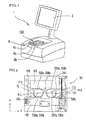
- Fig. 1 is a schematic view illustrating the appearance of an eyeglass frame shape measuring apparatus.
- the eyeglass frame shape measuring apparatus 1 includes a frame holding unit 100 which holds an eyeglass frame F in the desired state, and a measurement unit 200 to measure a three-dimensional shape (target lens shape) of a rim by inserting a tracing stylus into a groove (bevel groove) of the rim of an eyeglass frame held in the frame holding unit 100 and detecting a movement of the tracing stylus.
- a switch portion 4 is disposed in the apparatus 1.
- the switch portion 4 includes a switch 4a to start the measurement in a mode in which left and right rims are consecutively measured, a switch 4b to start the measurement in a mode in which the right rim is individually measured, and a switch 4c to start the measurement in a mode in which the left rim is individually measured.
- the switches 4a, 4b and 4c are switches serving as selection means for selecting the respective modes.
- a panel portion 3 having a touch panel-type display is disposed on a rear side of a casing of the apparatus 1.
- layout data of a lens with respect to target lens shape data, processing conditions of the lens, and the like can be input using the panel portion 3.
- the three-dimensional shape data of the rim obtained through the apparatus 1 and the data input through the panel portion 3 are transmitted to a processing apparatus of a circumferential edge of an eyeglass lens.
- the apparatus 1 may be configured to be built in the processing apparatus of a circumferential edge of an eyeglass lens.
- Fig. 2 is a top view of the frame holding unit 100 in which the eyeglass frame F is held.
- the measurement unit 200 is provided in a lower side of the frame holding unit 100.
- a first slider 102 and a second slider 103 are placed to hold the eyeglass frame F (right rim RIR and left rim RIL) in a substantially horizontal manner (including a case where the height of an upper side and the height of a lower side of the rim are different from each other by approximately 10 mm).
- the first slider 102 has a surface abutting on the lower side of the left rim RIL and the right rim RIR of the frame F in the longitudinal direction.
- the second slider 103 has a surface abutting on the upper side of the left rim RIL and the right rim RIR in the longitudinal direction.
- the first slider 102 and the second slider 103 are slidably disposed on two rails 111 so as to face each other having the center line FL in the center in the X direction, while being continuously pulled in a direction toward the center line FL of the both sliders by a spring 113.
- clamping pins 230a and 230b are respectively disposed at two places to clamp the left and right rims from the thickness direction (front side and rear side when eyeglasss are worn) of the rim.
- the clamping pins 230a and 230b are respectively disposed at two places to clamp the rims from the thickness direction of the rim.
- a configuration of the frame holding unit 100 for example, a well-known description of JP-A-2000-314617 can be used.
- Fig. 3 is a schematic configuration view of a clamping mechanism 2300 disposed on a right side of the first slider 102 to clamp the lower side of the left rim RIL.
- a base plate 2301 is disposed inside the first slider 102.
- the clamping pin 230a is attached to the tip of a first arm 2303.
- a center portion of the first arm 2303 is rotatably held with respect to the base plate 2301 by a rotational shaft 2304.
- the clamping pin 230b is attached to the tip of a second arm 2305.
- a center portion of the second arm 2305 is rotatably held with respect to the base plate 2301 by a rotational shaft 2306.
- a compression spring 2307 is attached between the first arm 2303 and the second arm 2305.
- a space between the two clamping pins 230a and 230b is continuously biased in the opening direction by the compression spring 2307.
- a gear 2309 is formed about the rotational shaft 2304 in the center portion of the first arm 2303.
- a gear 2311 is formed about the rotational shaft 2306 in the center portion of the second arm 2305 such that the gear 2309 is engaged with the gear 2311.
- a wire 2315 is fixed to the other end of the spring 2313.
- the wire 2315 is connected to a driving unit 2320 via a pulley 2317 which is rotatably attached to the base plate 2301.
- the driving unit 2320 has a shaft 2321 to wind the wire 2315 and a motor 2322 to rotate the shaft 2321. If the wire 2315 is pulled by driving the motor 2322, the first arm 2303 is rotated clockwise about the rotational shaft 2304. At this time, since the gear 2309 is engaged with the gear 2311, the second arm is rotated counterclockwise about the rotational shaft 2306. In this manner, the two clamping pins 230a and 230b are inter-connectedly closed such that the rim RIL is clamped by the two clamping pins 230a and 230b.
- the clamping mechanism which is disposed on the left side of the first slider 102 to clamp the lower side of the right rim RIR, is configured in a horizontally inverted manner with respect to the above-mentioned clamping mechanism 2300.
- the clamping mechanism which is disposed on two places of the left side and the right side of the second slider 103 to clamp the upper side of the left rim RIL and the right rim RIR, has the same configuration in an inverted manner in the longitudinal direction with respect to the clamping mechanism 2300 disposed on the first slider 102. Therefore, descriptions for the other clamping mechanism will not be repeated.
- the motor 2322 and the shaft 2321 may be configured to be respectively disposed in the clamping mechanism 2300 at four places.
- the motor 2322 and the shaft 2321 may be configured to be commonly used by the clamping mechanism 2300 at four places. In both cases, the clamping pins 230a and 230b at four places are configured to be opened and closed at the same time.
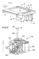
- Figs. 4 to 7 are configuration views of the measurement unit 200.
- Fig. 4 is a schematic configuration view of a movement unit 210.
- the measurement unit 200 includes a base portion 211 which has a square-shaped frame stretched in the horizontal direction (XY direction), a tracing stylus 281 which is inserted into a bevel groove of the rims (RIL and RIR), the movement unit 210 in which the tracing stylus 281 moves along the bevel groove of the rim.
- the base portion 211 is disposed under the frame holding unit 100.
- the movement unit 210 has a tracing stylus holding unit 250 holding a tracing stylus shaft 282 to which the tracing stylus 281 is attached at an upper end thereof, a Y movement unit 230 moving the tracing stylus holding unit 250 in the Y direction, an X movement unit 240 moving the Y movement unit 230 in the X direction, and a Z movement unit 220 moving the tracing stylus holding unit 250 in the Z direction vertical to the XY direction.
- a radial direction of the rim is set in the XY direction when tracing the rim and the vertical direction of a radial direction is set in the Z direction.
- the Y movement unit 230 includes a guide rail extending in the Y direction so as to move the tracing stylus holding unit 250 in the Y direction along the guide rail by driving a motor 235.
- the X movement unit 240 includes a guide rail 241 extending in the X direction so as to move the Y movement unit 230 in the X direction by driving a motor 245.
- the Z movement unit 220 is attached to the Y movement unit 230 so as to move the tracing stylus holding unit 250 in the Z direction along a guide rail 221 extending in the Z direction by driving a motor 225.
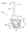
- the configuration of the tracing stylus holding unit 250 will be described based on Figs. 5 to 7 .
- the tracing stylus holding unit 250 movably holds the tracing stylus shaft 282 in the vertical direction (Z direction), while including a vertical tilt holding unit (hereinafter, referred to as VH unit) 280 which tiltably holds the tracing stylus shaft 282 in the tip direction (hereinafter, referred to as direction H) of the tracing stylus 281, and a rotation unit 260 which rotates the VH unit 280 about a shaft LO extending in the Z direction about the fulcrum set under the tracing stylus shaft 282.
- the tracing stylus 281 has a needle-shaped tip.
- the tracing stylus 281 is formed in a shape gradually tapering to the tip.
- a tip portion 281a of the tracing stylus 281 is formed in a spherical shape.
- the radius of the spherical shape of the tip portion 281a has a size which can be inserted into the groove of an ordinary lens frame, thereby being preferably 0.3 to 0.5 mm. Accordingly, even in a case where the rim is highly curved, or the rim is highly tilted (20 degrees or more) in the Z direction, the tip portion 281a is easily inserted into the bevel groove of the rim.
- Fig. 5 is an overall perspective view of the tracing stylus holding unit 250.
- the rotation unit 260 includes a rotation base 261 which holds the VH unit 280, a motor 265 which rotates the rotation base 261.
- the rotation base 261 holding the VH unit 280 is rotatably held by a Z movement support base 222 about the shaft LO extending in the Z direction.
- the Z movement support base 222 is guided by the guide rail 221 illustrated in Fig. 4 so as to move in the Z direction by driving the motor 225.
- the rotation base 261 rotates about the shaft LO via a rotation transmitting mechanism such as a gear by driving the motor 265.
- a rotation angle of the rotation base 261 is detected by an encoder 266 attached to the rotational shaft of the motor 265.
- the rotation angle of the rotation base 261 is controlled (managed) by the number of driving pulses of the motor 265.
- Figs. 6 and 7 are explanatory views of the configuration of the VH unit 280.
- a guide shaft 263 extending in the Z direction is fixed on the lower surface of a flange 262 which is integrally formed with the rotation base 261.
- Fig. 7 is an explanatory view of the VH unit 280 from which the rotation base 261 and the flange 262 are removed, and is an explanatory view of the VH unit 280 viewed from the rear side of the sheet, with respect to Fig. 6 .
- a Z movement support base 270 (see Fig. 7 ) of the VH unit 280 is fixed to a cylindrical member 264 passing through the guide shaft 263.
- the VH unit 280 is movably held in the Z direction along the guide shaft 263 via the Z movement support base 270 and the cylindrical member 264.
- the movable range of the VH unit 280 toward the Z direction is 4 mm, for example.
- the tracing stylus holding unit 250 includes a spring (bias member) 267 which reduces the load of the VH unit 280, and applies a moving force to cause the VH unit 280 (tracing stylus 281 and tracing stylus shaft 282) to face the upper direction (rear side direction of rim) with a small force.
- the spring 267 is provided between the flange 262 and the cylindrical member 264.
- the spring 267 is configured to apply a moving force to cause the VH unit 280 to face the upper direction.
- the spring 267 may be configured to apply a moving force to cause the VH unit 280 to face the lower direction (front side direction of rim).
- a movement position (movement position in the Z direction with respect to the rotation base 261) of the VH unit 280 in the Z direction is detected by an encoder 268, which is a position detector (see Fig. 7 ).
- the tracing stylus shaft 282 is tiltably held about a shaft S1 (fulcrum) in the H direction via a bearing 271 held in an upper portion of the Z movement support base 270.
- a rotation angle detecting plate 283 is attached to a lower portion of the tracing stylus shaft 282 via an attachment member 284.
- a tilt angle (rotation angle) of the tracing stylus shaft 282 about the shaft S1 in the H direction is detected via the rotation angle detecting plate 283 by an encoder 285 which is a rotation angle detector.
- a limiting member 291 abutting on a left end of the attachment member 284 is attached to a plate 292 of the Z movement support base 270.
- a spring (bias member) 290 as a measurement pressure adding mechanism to add a measurement pressure in the tip direction of the tracing stylus 281 is disposed between the attachment plate 284 and the cylindrical member 264.
- the tracing stylus shaft 282 is continuously biased by a biasing force (measurement pressure) so as to tilt in the tip direction Hf of the tracing stylus 281 by the spring 290.
- a tilt of the tracing stylus shaft 282 is limited in a state as in Fig. 7 by the attachment member 284 abutting on the limiting member 291.
- the initial state is a state where the tracing stylus shaft 282 is tilted as much as a predetermined angle (2 degrees) in the direction Hr which is opposite to the tip direction Hf of the tracing stylus 281 with respect to a Z shaft which is a vertical shaft.
- a regulating mechanism 295 see Fig.
- the regulating mechanism 295 is configured to be gradually increased in movable amount toward the upper direction in accordance with a tilt amount toward the direction Hr from the initial state of the tracing stylus shaft 282.
- the regulating mechanism 295 has a limiting plate on which a rotation member, which is attached to the lower end of the tracing stylus shaft 282, abuts.
- the limiting member is formed so as to gradually change in the height at which the rotation member abuts in accordance with the tilt amount of the tracing stylus shaft 282.
- the movable range of the VH unit 280 (tracing stylus 281) toward the upper direction is widened. If the tracing stylus shaft 282 is over-tilted more than a certain degree (for example, 8 degrees or greater) in the direction Hr, the regulating mechanism 295 is released. Then, the VH unit 280 (tracing stylus 281) is in a freely movable state within the movable range in the Z direction (vertical direction).
- a certain degree for example, 8 degrees or greater
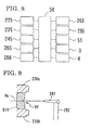
- Fig. 8 is a configuration view showing controlling of the apparatus 1.
- a controller 50 is connected to the motors 225, 235, 245 and 265, the encoders 268 and 285, the panel portion 3, the switch portion 4, a memory 51 which stores measurement data, and the like.
- a front side of the rim is defined as a side of the rim where the eye of the wearer is positioned, and a rear side of the rim is defined as a side of the rim opposite to the side where the eye of the wearer is positioned.
- an operator causes the eyeglass frame F to be interposed between the first slider 102 and the second slider 103, and then causes each upper side and lower side of the left rim RIL and the right rim RIR to be clamped by the clamping pins 230a and 230b.
- the initial position of the tracing stylus 281 in the XY direction is set to a position COR (see Fig. 2 ) of the right rim RIR side.
- the X direction of the position COR is on the center line FL which is the center of the Y direction
- the Y direction of the position COR is a position where the clamping pins 230a and 230b are disposed to clamp the lower side of the right rim RIR.
- the controller 50 rotates the rotation unit 260 such that the tip direction of the tracing stylus 281 faces the clamping pins 230a and 230b of the lower side of the right rim RIR in the initial position COR.
- the controller 50 controls the driving of the Z movement unit 220 (motor 225), and lift the tracing stylus holding unit 250 (moved in Z direction) such that the tip of the tracing stylus 281 is positioned in a center position Hc of the clamping pins 230a and 230b.
- Fig. 9 is a cross-sectional view of the rim in the Z direction at the starting point of the initial measurement.
- the controller 50 controls driving of the Y movement unit 230 (motor 235), and moves the tracing stylus holding unit 250 (tracing stylus 281) to the rim side such that the tracing stylus 281 positioned at the initial position COR is brought into contact with the rim. If a bevel groove RV is in the center of the front-to-rear width of the rim, the tip of the tracing stylus 281 is inserted into the bevel groove RV Then, the tip of the tracing stylus 281 is brought into contact with the rim. Moreover, the tracing stylus holding unit 250 is moved to the rim side such that the tracing stylus shaft 282 is tilted in the direction Hr.
- the encoder 285 detects that the tracing stylus shaft 282 is tilted from the initial state, and the fact that the tracing stylus 281 is brought into contact with the rim is detected by the result of the detection.
- the tracing stylus holding unit 250 is moved until the tracing stylus shaft 282 is tilted at a predetermined angle (8 degrees) in the direction Hr. If the tracing stylus shaft 282 is tilted at 8 degrees or greater in the direction Hr, the regulating mechanism 295 is released, and the VH unit 280 (tracing stylus 281) can be freely moved in the Z direction within a movable range in the Z direction.
- the controller 50 when measuring the rim in the radial direction, estimates changes in radius vector in an unmeasured part of the rim based on the information of the radius vector obtained after the measurement is started (already measured), decides the XY position to which the tracing stylus holding unit 250 moves such that the tip of the tracing stylus 281 is moved in accordance with the changes in radius vector of the unmeasured part, and controls driving of each motor of the movement unit 210 according to the decided XY position. Accordingly, the tracing stylus 281 smoothly tracks with respect to the changes in the rim such that the radius vector of the rim can be accurately measured.
- the controller 50 estimates changes in a Z position of unmeasured part of the rim based on information of the Z direction obtained after the measurement is started (already measured), decides the Z position to which the tracing stylus holding unit 250 moves such that the tip of the tracing stylus 281 is moved in accordance with the changes in the Z position of the unmeasured part, and controls driving of Z movement unit 220 (motor 225). Accordingly, similarly in the measurement in the Z direction, the tracing stylus 281 smoothly tracks with respect to the changes in the rim such that the Z position of the rim can be accurately measured.
- the controller 50 controls the movement unit 210 such that the tilt angle toward the direction Hr of the tracing stylus shaft 282 becomes larger. Accordingly, when measuring a high-curve frame, the tracing stylus 281 is reduced in possibility of derailing from the bevel groove of the rim, thereby making it possible to perform the measurement.
- the controller 50 recognizes the radius vector of the rim to be changed in the X direction, and moves the tracing stylus holding unit 250 in the X direction such that the tracing stylus 281 is moved in the X direction of the ear side (side where the ear of the wearer who wears the frame is positioned). Then, if the tip of the tracing stylus 281 is moved to track the changes in radius vector of the rim, the tracing stylus shaft 282 is tilted.
- the tilt angle of the tracing stylus shaft 282 is detected by the encoder 285 such that information of the XY position at the tip of the tracing stylus 281 with respect to a reference position of the tracing stylus holding unit 250 can be obtained.
- the controller 50 estimates the changes in following measurement points (unmeasured points). Then, based on the result thereof, the tracing stylus holding unit 250 is moved in the XY direction such that the tracing stylus 281 follows the rim RIR.
- the controller 50 controls driving of the motor 265 to rotate the VH unit 280 about the shaft LO by rotating the rotation base 261.
- the rotation angle at the moment is decided such that the tip direction of the tracing stylus 281 is in the normal direction with respect to the estimated changes in radius vector of the rim. Otherwise, the rotation angle may be decided in the intermediate direction between the radius vector angle about the position COR and the normal direction.
- the information of the radius vector (measurement data) of the whole circumference of the rim can be obtained by repeating the operation.
- the information of the XY position at the tip of the tracing stylus 281 with respect to the reference position of the tracing stylus holding unit 250 can be obtained through the detected information of the encoder 285 and the rotational information of the VH unit 280.
- the information of the radius vector (measurement data) of the rim can be obtained by the information of the XY position and the driving information of the motor 235 and 245 which cause the tracing stylus holding unit 250 to make a XY-movement.
- the tracing stylus 281 and the tracing stylus shaft 282 are moved in the Z direction tracking the changes in the rim toward the Z direction.
- the movement position of the tracing stylus shaft 282 in the Z direction is detected by the encoder 268 and the Z directional components of the encoder 285, thereby making it possible to obtain the information of the Z position of the tracing stylus 281 with respect to the reference position of the tracing stylus holding unit 250.
- the information of the Z position (measurement data) of the rim can be obtained by the information of the Z position and the driving information of the motor 225 which causes the tracing stylus holding unit 250 to make a Z-movement.
- Fig. 10 is a cross-sectional view of the rim in the Z direction at starting point of the initial measurement.
- the controller 50 moves the tracing stylus 281 positioned in the center position Hc at the initial position COR to the rim side.
- the controller 50 moves the tracing stylus 281 in the ear side direction or the nose side direction which are the X directions (nose side: a side where a nose of the wearer who wears the frame is positioned).
- the tracing stylus 281 is not inserted into the bevel groove RV so as to be moved in the X direction while being brought into contact with an inner wall RIe of the rim.
- the tracing stylus 281 since a force by which the VH unit 280 (tracing stylus 281) faces an upper direction (rear side direction of the rim) of the width direction of the rim is applied by the spring 267, the tracing stylus 281 is moved to the upper direction along the inner wall RIe of the rim, thereby derailing from the rim to cause a measurement failure. Further, even in a case where a force by which the VH unit 280 (tracing stylus 281) faces the front side direction of the rim is applied to the spring 267, the tracing stylus 281 is inserted into the bevel groove RV during the movement or derailed from the rim, thereby causing the measurement failure.
- a measurement failure caused by starting the measurement without having the tracing stylus 281 inserted into the bevel groove RV at the starting point of the initial measurement can be decided based on whether or not an abrupt change (abnormal data considered to be non-continuous) is present in measurement data obtained within a predetermined radius vector range RS (not illustrated) from the starting point of the initial measurement. That is, when the measurement is started in a state where the tracing stylus 281 is inserted into the bevel groove RV, the measurement data of the radial direction and the Z direction is consecutively and gradually changed.
- the controller 50 decides that the measurement failure is present in a case where the radius vector length of the measurement data is changed by 1 mm or more among the measurement points with the 0.36 degree intervals on the basis of the position COR.
- the controller 50 decides that the measurement failure is present in a case where the Z position of the measurement data is changed by 0.3 mm or more from three points behind (position of 1.08 degree retraced).
- Decision of the measurement failure is set within a predetermined radius vector range RS from the starting point of the initial measurement (for example, a range of 36 degrees from the starting point of the initial measurement or a range of 10 mm toward the X direction from the starting point of the initial measurement on the basis of the position COR).
- the controller 50 decides that a failure is present in the measurement within a predetermined radius vector range RS from the starting point of the initial measurement as described above, the controller 50 determines that a measurement failure, which is caused by starting the measurement in a state where the tracing stylus 281 is not inserted into the bevel groove RV at the starting point of the initial measurement, is present. Then, the controller 50 suspends the measurement for the moment, thereby automatically shifting to a remeasurement mode.
- the controller 50 changes at least a part of the movement operation regarding the movement control of the tracing stylus 281 when the remeasurement is started in a state that the tracing stylus 281 is inserted into the bevel groove RV of the rim at the measurement starting point. For example, the controller 50 returns the tracing stylus 281 back to the initial position COR for the moment, and then moves the tracing stylus 281 to the rim side, similar to the initial measurement operation.
- the controller 50 moves the tracing stylus holding unit 250 such that the tracing stylus shaft 282 is tilted within a range where the movement of the tracing stylus 281 in the Z direction is regulated by the regulating mechanism 295.
- the tracing stylus holding unit 250 is moved to the rim side such that the tracing stylus shaft 282 is tilted in the direction Hr from the initial state until the tilt amount (for example, 5 degrees) becomes smaller than the tilt amount of the tracing stylus shaft 282 (8 degrees) at which the regulating of the regulating mechanism 295 is completely released.
- movable amount of the VH unit 280 (tracing stylus 281) to the Z direction (vertical direction) is limited up to 2 mm in the upper direction from the lower limit.
- the position of the tracing stylus 281, which is brought into contact with the inner wall RIe of the rim, in the Z direction is substantially maintained in the center position of the front-to-rear width of the rim.
- the controller 50 controls driving of the movement unit 210 in a state where the position of the tracing stylus 281 in the Z direction is substantially maintained, and then moves the tracing stylus holding unit 250 (tracing stylus 281) to the ear side direction of the rim from the starting point of the initial measurement.
- the controller 50 controls driving of the motor 225 and moves the tracing stylus holding unit 250 to the lower direction (front direction of the rim) such that the position of the tracing stylus 281 in the Z direction faces the front side direction of the rim, while causing the tracing stylus holding unit 250 (tracing stylus 281) to move to the ear side direction of the rim from the starting point of the initial measurement.
- Fig. 11 is a view of the rim viewed from the initial position COR, and the view illustrates the tilt state of the rim and the bevel groove RV.
- PS1 denotes the tip position of the tracing stylus 281 at the starting point of the initial measurement
- PS2 denotes a position where the tracing stylus 281 is inserted into the bevel groove RV.
- the measurement data (information of radius vector) of the respective measurement points, through which the tracing stylus 281 is moved while being brought into contact with the inner wall RIe of the rim, is gradually changed.
- the controller 50 determines that the stage where an abrupt change is present in the information of the radius vector is the position where the tracing stylus 281 is inserted into the bevel groove RV during the measurement.
- the position PS2 is determined based on whether or not the information of the radius vector and the information of the Z position in the Z direction are gradually changed, after an abrupt change is present in the information of the radius vector. Then, when the controller 50 determines that the tracing stylus 281 is inserted into the bevel groove RV during the measurement, the controller 50 does not employ the measurement data (does not employ the data as the result of the measurement) from the starting point of the initial measurement PS1, thereby starting to newly obtain the measurement data.
- the controller 50 controls the movement unit 210 so as to return the tracing stylus 281 along the bevel groove RV from the position PS2 where the tracing stylus 281 is inserted into the bevel groove RV to the starting point of the initial measurement (position of the clamping pins 230a and 230b), and controls the movement unit 210 so as to obtain the measurement data of the whole circumferential shape of the rim by causing the tracing stylus 281 to move again from the starting point of the initial measurement to the ear side direction or the nose side direction of the rim.
- the measurement may be performed as follows.
- the controller 50 employs the position PS2 where the tracing stylus 281 is inserted into the bevel groove RV as the new starting point of the measurement, moves the tracing stylus 281 along the change of the bevel groove RV, and controls the movement unit 210 so as to obtain the measurement data of the whole circumference of the rim.
- the movement direction of the tracing stylus 281 may be any one of the ear side direction or the nose side direction of the rim.
- the controller 50 may controls the movement unit 210 so that the tracing stylus 281 contacts a position of the rim which is located a predetermined distance front (for example 1mm) from a center position of the rim in the front and rear direction, instead of contacting the center position.
- a predetermined distance front for example 1mm
- the tracing stylus 281 is inserted into the bevel groove RV at the measurement starting point of the remeasurement with high probability.
- the measurement data of the whole circumference of the right rim RIR is stored in a memory 51 (storing means). If the measurement of the right rim RIR is completed, the controller 50 controls the movement unit 210 to consecutively measure the left rim RIL and moves the tracing stylus 281 to the initial position COL (position set in the same manner as the position COR at the right rim RIR side) set at the left rim RIL side. Then the controller 50 moves the tracing stylus 281 to the starting point of the measurement of the left rim RIL from the initial position COL.
- the controller 50 does not set the position of the tracing stylus 281 in the Z direction to the center position Hc of the clamping pins 230a and 230b, but decides the Z direction position (position in the front and rear direction of the rim) of the tracing stylus 281 when the tracing stylus is moved toward the rim side based on the measurement data of the right rim RIR, which is stored in the memory 51. That is, the controller 50 reads out the Z direction position data at the position (initial measurement point of the radius vector) where the right rim RIR is clamped by the clamping pins 230a and 230b from the memory 51, thereby causing the tracing stylus 281 to move in the Z direction position likewise.
- the tracing stylus 281 is moved to the starting point of the initial measurement (position of clamping pins 230a and 230b) of the left rim RIL, the tracing stylus 281 is inserted into the bevel groove RV with a high probability of success from the first. If the tracing stylus 281 is inserted into the bevel groove RV at the starting point of the initial measurement, the whole circumference of the rim is measured under the normal measurement operation.
- the controller 50 decides that the tracing stylus 281 is not inserted into the bevel groove RV so as to cause the measurement failure at the starting point of the measurement, thereby performing the same control as in the right rim RIR.
- the sequential order of measurement in the right rim RIR and the left rim RIL is not limited thereto such that the left rim RIL may be measured in advance.
- the above-mentioned embodiment mainly describes the configuration in which a moving force is applied to the tracing stylus 281 brought into contact with the inner wall RIe of the rim to cause the tracing stylus 281 to face the upper direction (rear side direction of the rim).
- a configuration, in which a moving force is applied to the tracing stylus 281 to face the lower direction (front side direction of the rim) may be employed.
- the tracing stylus 281 In a case of the configuration in which a moving force is applied to the tracing stylus 281 to face the lower direction (front side direction of the rim), the tracing stylus 281 is brought into contact with the inner wall RIe of the rim, and then the tracing stylus 281 faces the lower direction (front side of the rim). Therefore, the tracing stylus 281 is inserted into the bevel groove RV which is positioned in the lower direction (front side of the rim) from the starting point of the initial measurement of the tracing stylus 281 with a high probability of success.
- the insertion status can be determined based on whether or not at least one of the information of the radius vector and the positional information of the Z direction which are included in the measurement data is equal to or more than a predetermined value.
- the changes in the radial direction of the tracing stylus 281 stop due to the abutting on the bevel groove RV. If the changes in the radial direction at the moment are set to be a predetermined value such as 5 mm, it is possible to determine whether or not the tracing stylus 281 is inserted into the bevel groove RV Similarly, in the Z direction, it is possible to determine whether or not the tracing stylus 281 is inserted into the bevel groove RV depending on whether or not the moving amount of the tracing stylus 281 is equal to or more than a predetermined value such as 3 mm.
- determining whether or not the tracing stylus 281 is inserted into the bevel groove RV can be done based on whether or not an abrupt change is present in at least one of the information of the radius vector and the information of the vertical direction which are included in the continuous measurement data.
- the tracing stylus 281 is continuously caused to move to the X direction, thereby determining whether or not the tracing stylus 281 is inserted into the bevel groove RV based on whether or not an abrupt change is present in the information of the radius vector and the information of the Z position within a predetermined radius vector range (for example, similar range as the above-mentioned radius vector range RS). That is, if the tracing stylus 281 is inserted into the bevel groove RV, the information of the radius vector and the information of the Z position of the continuous measurement data gradually change such that an abrupt change is no longer present.
- a predetermined radius vector range for example, similar range as the above-mentioned radius vector range RS
- the measurement data of the whole circumference of the rim can be obtained by causing the tracing stylus 281 to move in accordance with the changes in the bevel groove RV
- the controller 50 monitors whether or not an abrupt change is present in the measurement data. If there is any abrupt change is present, the controller 50 perceives a measurement failure and stops the measurement. In this case, an operator checks if the failure is caused due to the derailing of the tracing stylus 281 from the bevel groove RV. If the failure is caused due to the derailing of the tracing stylus 281 from the bevel groove RV, in the same manner as in the related art, the operator takes an action to insert the tracing stylus into the bevel groove with fingers, and then the operator may take a step to start the measurement of the rim.
- the configuration of the measurement unit 200 is not limited to the description of Figs. 4 to 7 . Even in the similar configuration as JP-A-2000-314617 , the invention can be applied.
- the tracing stylus is configured to be moved in the Z direction by driving of the motor.
- the regulating mechanism 295 described in the above-mentioned embodiment can cause the motor (motor to move the tracing stylus in the Z direction) to be switched to driving state. That is, the controller controls driving of the motor so as to cause the Z direction position of the position PS1 of the tracing stylus 281 brought into contact with the inner wall RIe of the rim as in the Fig.
- the tracing stylus 281 is inserted into the bevel groove RV
- the measurement data from the starting point of the initial measurement PS1 is no longer employed such that the measurement data of the whole circumference of the rim can be obtained through an operation similar to the above-mentioned embodiment.
- various modifications can be applied to the invention to be included in the invention.
Landscapes
- Physics & Mathematics (AREA)
- General Physics & Mathematics (AREA)
- Engineering & Computer Science (AREA)
- Health & Medical Sciences (AREA)
- Ophthalmology & Optometry (AREA)
- Optics & Photonics (AREA)
- Chemical & Material Sciences (AREA)
- Ceramic Engineering (AREA)
- Inorganic Chemistry (AREA)
- Mechanical Engineering (AREA)
- A Measuring Device Byusing Mechanical Method (AREA)
- Eyeglasses (AREA)
Applications Claiming Priority (1)
| Application Number | Priority Date | Filing Date | Title |
|---|---|---|---|
| JP2012195457A JP6172430B2 (ja) | 2012-09-05 | 2012-09-05 | 眼鏡枠形状測定装置 |
Publications (2)
| Publication Number | Publication Date |
|---|---|
| EP2706323A1 EP2706323A1 (en) | 2014-03-12 |
| EP2706323B1 true EP2706323B1 (en) | 2015-03-25 |
Family
ID=49084919
Family Applications (1)
| Application Number | Title | Priority Date | Filing Date |
|---|---|---|---|
| EP20130183074 Active EP2706323B1 (en) | 2012-09-05 | 2013-09-05 | Eyeglass frame shape measuring apparatus |
Country Status (3)
| Country | Link |
|---|---|
| US (1) | US9080853B2 (enExample) |
| EP (1) | EP2706323B1 (enExample) |
| JP (1) | JP6172430B2 (enExample) |
Families Citing this family (8)
| Publication number | Priority date | Publication date | Assignee | Title |
|---|---|---|---|---|
| US9535269B2 (en) * | 2013-06-24 | 2017-01-03 | Nidek Co., Ltd. | Eyeglass frame shape measuring apparatus |
| CN107179032A (zh) * | 2016-03-11 | 2017-09-19 | 上海强精金属制品有限公司 | 一种微波炉门检测装置 |
| WO2019049715A1 (ja) * | 2017-09-05 | 2019-03-14 | 株式会社ニデック | 眼鏡枠形状測定装置及び眼鏡枠形状測定プログラム |
| JP7052567B2 (ja) | 2018-05-31 | 2022-04-12 | 株式会社ニデック | 眼鏡レンズ加工制御データ取得装置 |
| JP7276050B2 (ja) | 2019-09-30 | 2023-05-18 | 株式会社ニデック | 眼鏡枠形状測定装置、及びレンズ加工装置 |
| EP3978863B1 (en) * | 2020-09-30 | 2025-06-11 | Nidek Co., Ltd. | Eyeglass frame shape measurement apparatus and control program for eyeglass frame shape measurement apparatus |
| CN112123800B (zh) * | 2020-10-16 | 2022-07-01 | 深圳市华成利工数控设备有限公司 | 眼镜腿插针设备 |
| WO2025028490A1 (ja) | 2023-08-01 | 2025-02-06 | 株式会社ニデック | 眼鏡レンズ加工用装置および眼鏡レンズ加工用装置に装着される載置ユニット |
Family Cites Families (15)
| Publication number | Priority date | Publication date | Assignee | Title |
|---|---|---|---|---|
| US5333412A (en) * | 1990-08-09 | 1994-08-02 | Nidek Co., Ltd. | Apparatus for and method of obtaining processing information for fitting lenses in eyeglasses frame and eyeglasses grinding machine |
| US5121550A (en) * | 1990-12-03 | 1992-06-16 | Gerber Optial, Inc. | Automatic surface tracer |
| JP2578354Y2 (ja) * | 1993-01-08 | 1998-08-13 | ホーヤ株式会社 | 眼鏡レンズ枠形状測定装置 |
| JPH0843071A (ja) * | 1994-07-27 | 1996-02-16 | Topcon Corp | レンズ枠形状測定装置 |
| JP3695988B2 (ja) | 1999-04-30 | 2005-09-14 | 株式会社ニデック | 眼鏡枠形状測定装置 |
| FR2870934B1 (fr) | 2004-05-28 | 2006-09-08 | Essilor Int | Appareil de lecture de contour comportant un palpeur mobile en rotation |
| FR2893723B1 (fr) * | 2005-11-23 | 2008-02-01 | Essilor Int | Appareil de lecture de contour de drageoir de cercle de monture de lunettes |
| FR2910136B1 (fr) | 2006-12-18 | 2009-02-27 | Essilor Int | Procede de correction de la geometrie d'une couche palpee approchant un brin longitudinal d'un drageoir de monture de lunettes et procede d'acquisition de la geometrie d'un contour d'un tel drageoir |
| JP4920514B2 (ja) | 2007-07-04 | 2012-04-18 | 株式会社ニデック | 玉型形状測定装置 |
| FR2934903B1 (fr) | 2008-08-07 | 2012-04-06 | Briot Int | Appareil de lecture de la geometrie d'un drageoir. |
| FR2950162B1 (fr) * | 2009-09-14 | 2011-10-07 | Essilor Int | Procede d'elaboration d'une consigne de detourage d'une lentille ophtalmique. |
| JP5562624B2 (ja) | 2009-12-09 | 2014-07-30 | 株式会社ニデック | 眼鏡枠形状測定装置 |
| JP5586930B2 (ja) | 2009-12-09 | 2014-09-10 | 株式会社ニデック | 眼鏡枠形状測定装置 |
| FR2983316B1 (fr) * | 2011-11-30 | 2014-06-27 | Essilor Int | Procede de preparation d'une lentille ophtalmique |
| US9535269B2 (en) * | 2013-06-24 | 2017-01-03 | Nidek Co., Ltd. | Eyeglass frame shape measuring apparatus |
-
2012
- 2012-09-05 JP JP2012195457A patent/JP6172430B2/ja active Active
-
2013
- 2013-09-04 US US14/017,755 patent/US9080853B2/en active Active
- 2013-09-05 EP EP20130183074 patent/EP2706323B1/en active Active
Also Published As
| Publication number | Publication date |
|---|---|
| US9080853B2 (en) | 2015-07-14 |
| JP6172430B2 (ja) | 2017-08-02 |
| JP2014052222A (ja) | 2014-03-20 |
| EP2706323A1 (en) | 2014-03-12 |
| US20140059871A1 (en) | 2014-03-06 |
Similar Documents
| Publication | Publication Date | Title |
|---|---|---|
| EP2706323B1 (en) | Eyeglass frame shape measuring apparatus | |
| JP5562624B2 (ja) | 眼鏡枠形状測定装置 | |
| JP3695988B2 (ja) | 眼鏡枠形状測定装置 | |
| JP5586930B2 (ja) | 眼鏡枠形状測定装置 | |
| KR101917394B1 (ko) | 안경 프레임 형상 측정 장치 | |
| US9535269B2 (en) | Eyeglass frame shape measuring apparatus | |
| EP0190450B1 (en) | Device for measuring the profile of spectacles lens frame | |
| JPH07223153A (ja) | フレーム形状測定装置 | |
| JP6080002B2 (ja) | 眼鏡レンズ加工装置 | |
| JP2001105293A (ja) | 玉型形状測定装置及びこれを有する眼鏡レンズ加工装置、並びに玉型形状測定装置のキャリブレーション方法 | |
| KR20030045616A (ko) | 렌즈테두리형상 측정장치 | |
| EP2105253B1 (en) | Eyeglass frame shape-measuring apparatus | |
| KR101952447B1 (ko) | 안경테 형상 측정 장치 | |
| JP5198978B2 (ja) | 眼鏡枠形状測定装置 | |
| JP6071103B2 (ja) | 眼鏡枠形状測定装置 | |
| US9144876B2 (en) | Eyeglass lens processing apparatus | |
| JP5850310B2 (ja) | 眼鏡枠形状測定装置 | |
| JP6319627B2 (ja) | 眼鏡レンズ周縁形状測定装置及び眼鏡レンズの周縁形状測定方法 | |
| JPH06241772A (ja) | フレーム形状測定装置 | |
| KR20160010089A (ko) | 차량용 헤드 업 디스플레이 장치 | |
| KR100881031B1 (ko) | 안경테 홈 리딩 기능을 갖는 안경테 형상 측정기 | |
| JP2015196215A (ja) | 眼鏡レンズ周縁形状測定装置及び眼鏡レンズ周縁形状測定プログラム | |
| JPH07186026A (ja) | フレーム形状測定装置 | |
| JP2022057964A (ja) | 眼鏡枠形状測定装置及び眼鏡枠形状測定装置の制御プログラム | |
| KR20180009609A (ko) | 학습기능을 이용한 프레임 형상 검출 방법 |
Legal Events
| Date | Code | Title | Description |
|---|---|---|---|
| PUAI | Public reference made under article 153(3) epc to a published international application that has entered the european phase |
Free format text: ORIGINAL CODE: 0009012 |
|
| AK | Designated contracting states |
Kind code of ref document: A1 Designated state(s): AL AT BE BG CH CY CZ DE DK EE ES FI FR GB GR HR HU IE IS IT LI LT LU LV MC MK MT NL NO PL PT RO RS SE SI SK SM TR |
|
| AX | Request for extension of the european patent |
Extension state: BA ME |
|
| 17P | Request for examination filed |
Effective date: 20140910 |
|
| RBV | Designated contracting states (corrected) |
Designated state(s): AL AT BE BG CH CY CZ DE DK EE ES FI FR GB GR HR HU IE IS IT LI LT LU LV MC MK MT NL NO PL PT RO RS SE SI SK SM TR |
|
| GRAP | Despatch of communication of intention to grant a patent |
Free format text: ORIGINAL CODE: EPIDOSNIGR1 |
|
| RAP1 | Party data changed (applicant data changed or rights of an application transferred) |
Owner name: NIDEK CO., LTD. |
|
| INTG | Intention to grant announced |
Effective date: 20141110 |
|
| GRAS | Grant fee paid |
Free format text: ORIGINAL CODE: EPIDOSNIGR3 |
|
| GRAA | (expected) grant |
Free format text: ORIGINAL CODE: 0009210 |
|
| AK | Designated contracting states |
Kind code of ref document: B1 Designated state(s): AL AT BE BG CH CY CZ DE DK EE ES FI FR GB GR HR HU IE IS IT LI LT LU LV MC MK MT NL NO PL PT RO RS SE SI SK SM TR |
|
| REG | Reference to a national code |
Ref country code: GB Ref legal event code: FG4D |
|
| REG | Reference to a national code |
Ref country code: CH Ref legal event code: EP |
|
| REG | Reference to a national code |
Ref country code: IE Ref legal event code: FG4D |
|
| REG | Reference to a national code |
Ref country code: DE Ref legal event code: R096 Ref document number: 602013001300 Country of ref document: DE Effective date: 20150507 |
|
| REG | Reference to a national code |
Ref country code: AT Ref legal event code: REF Ref document number: 718130 Country of ref document: AT Kind code of ref document: T Effective date: 20150515 |
|
| PG25 | Lapsed in a contracting state [announced via postgrant information from national office to epo] |
Ref country code: SE Free format text: LAPSE BECAUSE OF FAILURE TO SUBMIT A TRANSLATION OF THE DESCRIPTION OR TO PAY THE FEE WITHIN THE PRESCRIBED TIME-LIMIT Effective date: 20150325 Ref country code: FI Free format text: LAPSE BECAUSE OF FAILURE TO SUBMIT A TRANSLATION OF THE DESCRIPTION OR TO PAY THE FEE WITHIN THE PRESCRIBED TIME-LIMIT Effective date: 20150325 Ref country code: LT Free format text: LAPSE BECAUSE OF FAILURE TO SUBMIT A TRANSLATION OF THE DESCRIPTION OR TO PAY THE FEE WITHIN THE PRESCRIBED TIME-LIMIT Effective date: 20150325 Ref country code: HR Free format text: LAPSE BECAUSE OF FAILURE TO SUBMIT A TRANSLATION OF THE DESCRIPTION OR TO PAY THE FEE WITHIN THE PRESCRIBED TIME-LIMIT Effective date: 20150325 |
|
| REG | Reference to a national code |
Ref country code: AT Ref legal event code: MK05 Ref document number: 718130 Country of ref document: AT Kind code of ref document: T Effective date: 20150325 |
|
| REG | Reference to a national code |
Ref country code: LT Ref legal event code: MG4D |
|
| PG25 | Lapsed in a contracting state [announced via postgrant information from national office to epo] |
Ref country code: GR Free format text: LAPSE BECAUSE OF FAILURE TO SUBMIT A TRANSLATION OF THE DESCRIPTION OR TO PAY THE FEE WITHIN THE PRESCRIBED TIME-LIMIT Effective date: 20150626 Ref country code: LV Free format text: LAPSE BECAUSE OF FAILURE TO SUBMIT A TRANSLATION OF THE DESCRIPTION OR TO PAY THE FEE WITHIN THE PRESCRIBED TIME-LIMIT Effective date: 20150325 Ref country code: RS Free format text: LAPSE BECAUSE OF FAILURE TO SUBMIT A TRANSLATION OF THE DESCRIPTION OR TO PAY THE FEE WITHIN THE PRESCRIBED TIME-LIMIT Effective date: 20150325 |
|
| PG25 | Lapsed in a contracting state [announced via postgrant information from national office to epo] |
Ref country code: NL Free format text: LAPSE BECAUSE OF FAILURE TO SUBMIT A TRANSLATION OF THE DESCRIPTION OR TO PAY THE FEE WITHIN THE PRESCRIBED TIME-LIMIT Effective date: 20150325 |
|
| PG25 | Lapsed in a contracting state [announced via postgrant information from national office to epo] |
Ref country code: CZ Free format text: LAPSE BECAUSE OF FAILURE TO SUBMIT A TRANSLATION OF THE DESCRIPTION OR TO PAY THE FEE WITHIN THE PRESCRIBED TIME-LIMIT Effective date: 20150325 Ref country code: ES Free format text: LAPSE BECAUSE OF FAILURE TO SUBMIT A TRANSLATION OF THE DESCRIPTION OR TO PAY THE FEE WITHIN THE PRESCRIBED TIME-LIMIT Effective date: 20150325 Ref country code: RO Free format text: LAPSE BECAUSE OF FAILURE TO SUBMIT A TRANSLATION OF THE DESCRIPTION OR TO PAY THE FEE WITHIN THE PRESCRIBED TIME-LIMIT Effective date: 20150325 Ref country code: EE Free format text: LAPSE BECAUSE OF FAILURE TO SUBMIT A TRANSLATION OF THE DESCRIPTION OR TO PAY THE FEE WITHIN THE PRESCRIBED TIME-LIMIT Effective date: 20150325 Ref country code: PT Free format text: LAPSE BECAUSE OF FAILURE TO SUBMIT A TRANSLATION OF THE DESCRIPTION OR TO PAY THE FEE WITHIN THE PRESCRIBED TIME-LIMIT Effective date: 20150727 Ref country code: SK Free format text: LAPSE BECAUSE OF FAILURE TO SUBMIT A TRANSLATION OF THE DESCRIPTION OR TO PAY THE FEE WITHIN THE PRESCRIBED TIME-LIMIT Effective date: 20150325 |
|
| PG25 | Lapsed in a contracting state [announced via postgrant information from national office to epo] |
Ref country code: AT Free format text: LAPSE BECAUSE OF FAILURE TO SUBMIT A TRANSLATION OF THE DESCRIPTION OR TO PAY THE FEE WITHIN THE PRESCRIBED TIME-LIMIT Effective date: 20150325 Ref country code: PL Free format text: LAPSE BECAUSE OF FAILURE TO SUBMIT A TRANSLATION OF THE DESCRIPTION OR TO PAY THE FEE WITHIN THE PRESCRIBED TIME-LIMIT Effective date: 20150325 Ref country code: IS Free format text: LAPSE BECAUSE OF FAILURE TO SUBMIT A TRANSLATION OF THE DESCRIPTION OR TO PAY THE FEE WITHIN THE PRESCRIBED TIME-LIMIT Effective date: 20150725 |
|
| REG | Reference to a national code |
Ref country code: DE Ref legal event code: R097 Ref document number: 602013001300 Country of ref document: DE |
|
| PG25 | Lapsed in a contracting state [announced via postgrant information from national office to epo] |
Ref country code: DK Free format text: LAPSE BECAUSE OF FAILURE TO SUBMIT A TRANSLATION OF THE DESCRIPTION OR TO PAY THE FEE WITHIN THE PRESCRIBED TIME-LIMIT Effective date: 20150325 |
|
| PLBE | No opposition filed within time limit |
Free format text: ORIGINAL CODE: 0009261 |
|
| STAA | Information on the status of an ep patent application or granted ep patent |
Free format text: STATUS: NO OPPOSITION FILED WITHIN TIME LIMIT |
|
| 26N | No opposition filed |
Effective date: 20160105 |
|
| PG25 | Lapsed in a contracting state [announced via postgrant information from national office to epo] |
Ref country code: IT Free format text: LAPSE BECAUSE OF FAILURE TO SUBMIT A TRANSLATION OF THE DESCRIPTION OR TO PAY THE FEE WITHIN THE PRESCRIBED TIME-LIMIT Effective date: 20150325 Ref country code: MC Free format text: LAPSE BECAUSE OF FAILURE TO SUBMIT A TRANSLATION OF THE DESCRIPTION OR TO PAY THE FEE WITHIN THE PRESCRIBED TIME-LIMIT Effective date: 20150325 Ref country code: LU Free format text: LAPSE BECAUSE OF FAILURE TO SUBMIT A TRANSLATION OF THE DESCRIPTION OR TO PAY THE FEE WITHIN THE PRESCRIBED TIME-LIMIT Effective date: 20150905 |
|
| PG25 | Lapsed in a contracting state [announced via postgrant information from national office to epo] |
Ref country code: SI Free format text: LAPSE BECAUSE OF FAILURE TO SUBMIT A TRANSLATION OF THE DESCRIPTION OR TO PAY THE FEE WITHIN THE PRESCRIBED TIME-LIMIT Effective date: 20150325 |
|
| REG | Reference to a national code |
Ref country code: IE Ref legal event code: MM4A |
|
| PG25 | Lapsed in a contracting state [announced via postgrant information from national office to epo] |
Ref country code: IE Free format text: LAPSE BECAUSE OF NON-PAYMENT OF DUE FEES Effective date: 20150905 |
|
| REG | Reference to a national code |
Ref country code: FR Ref legal event code: PLFP Year of fee payment: 4 |
|
| PG25 | Lapsed in a contracting state [announced via postgrant information from national office to epo] |
Ref country code: BE Free format text: LAPSE BECAUSE OF FAILURE TO SUBMIT A TRANSLATION OF THE DESCRIPTION OR TO PAY THE FEE WITHIN THE PRESCRIBED TIME-LIMIT Effective date: 20150325 |
|
| PG25 | Lapsed in a contracting state [announced via postgrant information from national office to epo] |
Ref country code: MT Free format text: LAPSE BECAUSE OF FAILURE TO SUBMIT A TRANSLATION OF THE DESCRIPTION OR TO PAY THE FEE WITHIN THE PRESCRIBED TIME-LIMIT Effective date: 20150325 |
|
| REG | Reference to a national code |
Ref country code: CH Ref legal event code: PL |
|
| PG25 | Lapsed in a contracting state [announced via postgrant information from national office to epo] |
Ref country code: BG Free format text: LAPSE BECAUSE OF FAILURE TO SUBMIT A TRANSLATION OF THE DESCRIPTION OR TO PAY THE FEE WITHIN THE PRESCRIBED TIME-LIMIT Effective date: 20150325 Ref country code: NO Free format text: LAPSE BECAUSE OF FAILURE TO SUBMIT A TRANSLATION OF THE DESCRIPTION OR TO PAY THE FEE WITHIN THE PRESCRIBED TIME-LIMIT Effective date: 20150625 Ref country code: HU Free format text: LAPSE BECAUSE OF FAILURE TO SUBMIT A TRANSLATION OF THE DESCRIPTION OR TO PAY THE FEE WITHIN THE PRESCRIBED TIME-LIMIT; INVALID AB INITIO Effective date: 20130905 |
|
| PG25 | Lapsed in a contracting state [announced via postgrant information from national office to epo] |
Ref country code: CY Free format text: LAPSE BECAUSE OF FAILURE TO SUBMIT A TRANSLATION OF THE DESCRIPTION OR TO PAY THE FEE WITHIN THE PRESCRIBED TIME-LIMIT Effective date: 20150325 |
|
| PG25 | Lapsed in a contracting state [announced via postgrant information from national office to epo] |
Ref country code: LI Free format text: LAPSE BECAUSE OF NON-PAYMENT OF DUE FEES Effective date: 20160930 Ref country code: CH Free format text: LAPSE BECAUSE OF NON-PAYMENT OF DUE FEES Effective date: 20160930 |
|
| REG | Reference to a national code |
Ref country code: FR Ref legal event code: PLFP Year of fee payment: 5 |
|
| PG25 | Lapsed in a contracting state [announced via postgrant information from national office to epo] |
Ref country code: SM Free format text: LAPSE BECAUSE OF FAILURE TO SUBMIT A TRANSLATION OF THE DESCRIPTION OR TO PAY THE FEE WITHIN THE PRESCRIBED TIME-LIMIT Effective date: 20150325 |
|
| PG25 | Lapsed in a contracting state [announced via postgrant information from national office to epo] |
Ref country code: TR Free format text: LAPSE BECAUSE OF FAILURE TO SUBMIT A TRANSLATION OF THE DESCRIPTION OR TO PAY THE FEE WITHIN THE PRESCRIBED TIME-LIMIT Effective date: 20150325 Ref country code: MK Free format text: LAPSE BECAUSE OF FAILURE TO SUBMIT A TRANSLATION OF THE DESCRIPTION OR TO PAY THE FEE WITHIN THE PRESCRIBED TIME-LIMIT Effective date: 20150325 |
|
| REG | Reference to a national code |
Ref country code: FR Ref legal event code: PLFP Year of fee payment: 6 |
|
| PG25 | Lapsed in a contracting state [announced via postgrant information from national office to epo] |
Ref country code: AL Free format text: LAPSE BECAUSE OF FAILURE TO SUBMIT A TRANSLATION OF THE DESCRIPTION OR TO PAY THE FEE WITHIN THE PRESCRIBED TIME-LIMIT Effective date: 20150325 |
|
| PGFP | Annual fee paid to national office [announced via postgrant information from national office to epo] |
Ref country code: GB Payment date: 20210728 Year of fee payment: 9 Ref country code: DE Payment date: 20210727 Year of fee payment: 9 |
|
| REG | Reference to a national code |
Ref country code: DE Ref legal event code: R119 Ref document number: 602013001300 Country of ref document: DE |
|
| GBPC | Gb: european patent ceased through non-payment of renewal fee |
Effective date: 20220905 |
|
| P01 | Opt-out of the competence of the unified patent court (upc) registered |
Effective date: 20230517 |
|
| PG25 | Lapsed in a contracting state [announced via postgrant information from national office to epo] |
Ref country code: DE Free format text: LAPSE BECAUSE OF NON-PAYMENT OF DUE FEES Effective date: 20230401 |
|
| PG25 | Lapsed in a contracting state [announced via postgrant information from national office to epo] |
Ref country code: GB Free format text: LAPSE BECAUSE OF NON-PAYMENT OF DUE FEES Effective date: 20220905 |
|
| PGFP | Annual fee paid to national office [announced via postgrant information from national office to epo] |
Ref country code: FR Payment date: 20250808 Year of fee payment: 13 |