EP2705964A1 - Anwendung zum Fixieren von Radfelgen auf Reparaturwerkstattmaschinen oder dergleichen - Google Patents
Anwendung zum Fixieren von Radfelgen auf Reparaturwerkstattmaschinen oder dergleichen Download PDFInfo
- Publication number
- EP2705964A1 EP2705964A1 EP13155355.4A EP13155355A EP2705964A1 EP 2705964 A1 EP2705964 A1 EP 2705964A1 EP 13155355 A EP13155355 A EP 13155355A EP 2705964 A1 EP2705964 A1 EP 2705964A1
- Authority
- EP
- European Patent Office
- Prior art keywords
- jaws
- appliance
- adjustment
- fact
- movement means
- Prior art date
- Legal status (The legal status is an assumption and is not a legal conclusion. Google has not performed a legal analysis and makes no representation as to the accuracy of the status listed.)
- Granted
Links
Images


Classifications
-
- B—PERFORMING OPERATIONS; TRANSPORTING
- B60—VEHICLES IN GENERAL
- B60C—VEHICLE TYRES; TYRE INFLATION; TYRE CHANGING; CONNECTING VALVES TO INFLATABLE ELASTIC BODIES IN GENERAL; DEVICES OR ARRANGEMENTS RELATED TO TYRES
- B60C25/00—Apparatus or tools adapted for mounting, removing or inspecting tyres
- B60C25/01—Apparatus or tools adapted for mounting, removing or inspecting tyres for removing tyres from or mounting tyres on wheels
- B60C25/05—Machines
- B60C25/053—Support of wheel parts during machine operation
- B60C25/0539—Support of wheel parts during machine operation radially fixing the rim, e.g. with gripping claws
-
- B—PERFORMING OPERATIONS; TRANSPORTING
- B60—VEHICLES IN GENERAL
- B60C—VEHICLE TYRES; TYRE INFLATION; TYRE CHANGING; CONNECTING VALVES TO INFLATABLE ELASTIC BODIES IN GENERAL; DEVICES OR ARRANGEMENTS RELATED TO TYRES
- B60C25/00—Apparatus or tools adapted for mounting, removing or inspecting tyres
- B60C25/01—Apparatus or tools adapted for mounting, removing or inspecting tyres for removing tyres from or mounting tyres on wheels
- B60C25/02—Tyre levers or the like, e.g. hand-held
- B60C25/025—Tyre levers or the like, e.g. hand-held with a jack
-
- B—PERFORMING OPERATIONS; TRANSPORTING
- B60—VEHICLES IN GENERAL
- B60C—VEHICLE TYRES; TYRE INFLATION; TYRE CHANGING; CONNECTING VALVES TO INFLATABLE ELASTIC BODIES IN GENERAL; DEVICES OR ARRANGEMENTS RELATED TO TYRES
- B60C25/00—Apparatus or tools adapted for mounting, removing or inspecting tyres
- B60C25/01—Apparatus or tools adapted for mounting, removing or inspecting tyres for removing tyres from or mounting tyres on wheels
- B60C25/05—Machines
- B60C25/053—Support of wheel parts during machine operation
- B60C25/0545—Support of wheel parts during machine operation with rotary motion of tool or tyre support, e.g. turntables
-
- B—PERFORMING OPERATIONS; TRANSPORTING
- B60—VEHICLES IN GENERAL
- B60C—VEHICLE TYRES; TYRE INFLATION; TYRE CHANGING; CONNECTING VALVES TO INFLATABLE ELASTIC BODIES IN GENERAL; DEVICES OR ARRANGEMENTS RELATED TO TYRES
- B60C25/00—Apparatus or tools adapted for mounting, removing or inspecting tyres
- B60C25/01—Apparatus or tools adapted for mounting, removing or inspecting tyres for removing tyres from or mounting tyres on wheels
- B60C25/02—Tyre levers or the like, e.g. hand-held
- B60C25/04—Tyre levers or the like, e.g. hand-held pivotal about the wheel axis, or movable along the rim edge, e.g. rollable
-
- B—PERFORMING OPERATIONS; TRANSPORTING
- B60—VEHICLES IN GENERAL
- B60C—VEHICLE TYRES; TYRE INFLATION; TYRE CHANGING; CONNECTING VALVES TO INFLATABLE ELASTIC BODIES IN GENERAL; DEVICES OR ARRANGEMENTS RELATED TO TYRES
- B60C25/00—Apparatus or tools adapted for mounting, removing or inspecting tyres
- B60C25/01—Apparatus or tools adapted for mounting, removing or inspecting tyres for removing tyres from or mounting tyres on wheels
- B60C25/05—Machines
- B60C25/132—Machines for removing and mounting tyres
- B60C25/135—Machines for removing and mounting tyres having a tyre support or a tool, movable along wheel axis
- B60C25/138—Machines for removing and mounting tyres having a tyre support or a tool, movable along wheel axis with rotary motion of tool or tyre support
Definitions
- the present invention relates to an appliance for locking wheel rims for vehicles on repair workshop machines or the like.
- Such tyre-changing machines generally consist of a base structure supporting means for gripping and placing in rotation the rim of a wheel, having a rim locking spindle, and of at least a tool bearing arm having one or more tools suitable for removing and/or fitting the tyre from and onto the rim.
- a particular type of means for gripping and placing in rotation the rim is made up of gripping means for gripping the edge of the rim of the wheel.
- These gripping means for gripping the edge of the rim can be composed of, e.g., a so-called spindle with jaw lock.
- the spindle with jaw lock consists of a fastening plate for the rim, which is fitted on the base structure of the tyre-changing machine in a rotatable way around a central work axis and which has four gripping jaws of the edge of the rim.
- the jaws are fitted on respective supporting slides and move, due to the action of suitable actuators, from the centre towards the outside of the plate and vice versa, between a closing configuration, corresponding to the positioning of the jaws at the centre of the plate, and an opening configuration, corresponding to the positioning of the jaws at the periphery of the plate.
- the jaws can be used so as to engage on the edge of the rim both from the outside and the inside.
- the jaws are engaged in correspondence to respective sections of the edge of the rim, so as to lock the rim itself onto the plate.
- the need is also known to make a further adjustment of the position of the jaws, irrespective of the adjustment commonly made by means of the actuators, so as to also allow the use of the spindle for rims of different dimensions.
- the document EP 1 518 718 is known, wherein is described a self-centring gripping device for tyre-changing machines comprising a supporting plate having a plurality of radial slats, equidistant from one another, inside which are inserted sliding relative gripping jaws of a rim.
- the jaws are connected to one another by means of a system of levers, so they are always equally distant with respect to the rotation axis of the plate, and are associated with actuator means suitable for causing their translation in a radial direction.
- a positioning device suitable for changing the work position of the jaws, with respect to the actuator, without changing its stroke.
- the positioning device comprises a crankshaft with a crank, the button of which is suitable for being received by a bush integral with one of the jaws, and the outer pins of which are connected to operating means.
- Special locking means are suitable for locking the crankshaft in two opposite contrasting work positions.
- the positioning device used is structurally complex and its realization has a significant influence on the manufacturing times and costs of the self-centring gripping spindle of the tyre-changing machine.
- Another drawback is represented by the fact that the positioning device used only permits positioning the jaws in two extreme positions and does not therefore permit making a precise adjustment of the position of the gripping jaws in accordance with the specific dimensions of the rim to be locked. Furthermore, the possibility of only positioning the jaws in two extreme positions makes necessary continuous adjustment operations including in the event of its being necessary to operate in sequence on the rims with different dimensions the one from the other but which, in any case do not have extreme dimensions.
- the main object of the present invention is to provide an appliance for locking the wheel rims for vehicles on repair workshop machines or the like which allows a further adjustment of the position of the jaws, irrespective of the adjustment made by means of the actuators, by means of a solution which is structurally simple, rational, easy and effective to use and which is inexpensive.
- Another object of the present invention is to provide an appliance for locking the wheel rims for vehicles on repair workshop machines or the like which allows a precise adjustment of the position of the gripping jaws, which can be made in accordance with the specific dimensions of the rim to be locked.
- Another object of the present invention is to provide an appliance for locking the wheel rims for vehicles on repair workshop machines or the like which permits considerably reducing the number of jobs required to adjust the jaws during the fitting/removal operations on rims of different dimensions.
- the present appliance for locking wheel rims for vehicles on repair workshop machines or the like, comprising:
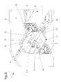
- an appliance for locking wheel rims for vehicles particularly used to lock the rim of a wheel on repair workshop machines, such as tyre-changing machine or the like.
- the appliance 1 comprises supporting means 2 associable with conventional rotation means A of a machine B.
- the supporting means 2 can be made up of a plate that can be fixed to the rotation means A of the machine B, suitable for supporting the rim of a wheel.
- the appliance 1 also comprises at least two jaws 3 for locking the rim associated with the plate 2 and moving along a reciprocal direction of moving close/away D between a maximum opening position, wherein they are arranged at a maximum distance the one from the other, and a minimum opening position, wherein they are arranged at a minimum distance the one from the other.
- the appliance 1 comprises two pairs of jaws 3 which move along respective directions of moving close/away D at right angles the one to the other.
- the plate 2 has four guides 4, made up e.g. of radial slots and angularly equidistant, inside which are fitted sliding respective carriages 5 for supporting each of the jaws 3.
- Different supporting means 2 cannot however be ruled out, having plates with different shapes and dimensions with respect to that shown in the illustrations and having slots 4 for guiding the jaws 3 of different number, conformation and inclination.
- the appliance 1 comprises movement means 6 connected to each of the jaws 3 and suitable for moving the jaws 3 between the maximum opening position and the minimum opening position.
- the movement means 6 comprise an opportune system of self-centring levers connected to each of the jaws 3 suitable for keeping each of the jaws 3 always at the same distance with respect to a central axis C for the rotation of the plate 2.
- the movement means 6 comprise two linear actuators 7.
- the linear actuators 7 can be made up, e.g., of actuator cylinders with fluid operation.
- the system of self-centring levers is arranged below the plate 2 and comprises four pairs of connecting rods 8 articulated, at one extremity, to a lower portion of respective carriages 5 and articulated, at the opposite extremities, to the corners of two respective rotatable plates 9.
- the rotatable plates 9 are substantially square and are mounted substantially superimposed and idle on a central pin 10 of the plate 2, so the connecting rods 8 of each single pair are symmetrically arranged the one to the other with respect to the direction of moving close/away D of the respective jaw 3.
- the appliance 1 comprises at least one adjustment device 11, placed between the movement means 6 and at least one of the jaws 3 and suitable for adjusting the maximum opening position and the minimum opening position of the jaws themselves.
- the adjustment device 11 therefore permits adjusting the distance between the jaws 3 according to the size of the rim to be locked, without having to change the stroke of the linear actuators 7 used.
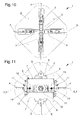
- the adjustment device 11 shown in detail and in a preferred embodiment in the figures 2 and 3 , comprises:
- the rotation of the adjustment element 12 around its longitudinal axis E permits moving the mobile element 13 on the threaded portion, along a direction of adjustment F parallel to the direction of moving close/away of the jaw 3.
- the adjustment element 12 can be composed of a pin having at least one threaded section.
- the adjustment device 11 comprises a gripping element 15 fixed integral to an extremity of the pin 12, arranged so as to be easily reachable and suitable for making it easier for the operator to grip and rotate the pin itself.
- the gripping element 15 can be composed of a specific knob fixed integral to the extremity of the pin 12 turned outwards.
- the pin 12 is connected axially revolving to a connection element 16 fixed to the linear actuators 7.
- connection element 16 is made up of a body of elongated shape having two opposite extremities fixed to the extremities of each of the pistons of the linear actuators 7, respectively.
- connection element 16 also comprises a central portion having a through hole inside which the pin 12 is inserted axially rotatable.
- a first and a second thrust bearing fastened to the pin 12 in correspondence to sections opposite the through hole on the connection element 16, prevent the movement of the pin 12 with respect to the connection element 16 along the longitudinal axis E.
- the mobile element 13 is substantially cup-shaped and the pin 12 is at least in part housed inside it.
- the adjustment device 11 comprises guide means 17 for guiding the translation of the mobile element 13 with respect to the pin 12.
- the guide means 17 are made of a pair of straight and elongated slots 17 extending on walls of the mobile element 13 opposite with respect to the pin 12, along a direction parallel to the direction of adjustment F, inside which are fitted sliding respective portions of the connection element.
- the appliance 1 comprises two adjustment devices 11, placed in between the linear actuators 7 and respective and opposite jaws 3.
- a second adjustment device 11 has the respective connection element 16 with the opposite extremities fixed to the extremities of each of the cylinders of the linear actuators 7, respectively.
- the appliance 1 is shown with the linear actuators 7 fully extended and, therefore, with the jaws 3 separated from one another in the maximum opening position.
- the appliance 1 is shown with the linear actuators 7 fully collected up and, therefore, with the jaws 3 close to one another in the minimum opening position.
- an operator can e.g. adjust one of the adjustment devices 11, unscrewing the pin 12 up to end of stroke, moving the mobile element 13 along the direction of adjustment F and towards the centre of the plate 2.
- the movement of the mobile element 13 corresponds to the movement of the carriage 5 to which it is fixed and, consequently, all the jaws 3 are moved closer to one another being connected to one another by the self-centring lever system ( figures 6 and 7 ).
- the operation of the second adjustment device 11 permits further moving the jaws 3 closer to one another.
- the operator can adjust the second adjustment device 11, by unscrewing the pin 12 up to end of stroke, moving the second mobile element 13 along the direction of adjustment F and towards the centre of the plate 2.
- the movement of the second mobile element 13 corresponds to a further movement of the carriage 5 to which it is fixed and, consequently, to a further movement of all the jaws ( figures 8 and 9 ).
- the adjustment device 11 permits a further adjustment of the position of the jaws 3, irrespective of the adjustment made by means of the linear actuators 7, by means of a solution which is structurally simple, rational, easy and effective to use and inexpensive.
- the adjustment device 11 permits accurately adjusting the position of the gripping jaws 3, which can be performed according to the specific dimensions of the rim to be locked.
- the particular adjustment device 11 permits considerably reducing the number of jobs required to adjust the jaws during the fitting/removal operations on rims of different dimensions.
Landscapes
- Engineering & Computer Science (AREA)
- Mechanical Engineering (AREA)
- Vehicle Cleaning, Maintenance, Repair, Refitting, And Outriggers (AREA)
- Lock And Its Accessories (AREA)
Applications Claiming Priority (1)
| Application Number | Priority Date | Filing Date | Title |
|---|---|---|---|
| IT000212A ITMO20120212A1 (it) | 2012-09-07 | 2012-09-07 | Apparecchiatura per il bloccaggio di cerchi di ruote per veicoli in macchine da autofficina o simili |
Publications (2)
| Publication Number | Publication Date |
|---|---|
| EP2705964A1 true EP2705964A1 (de) | 2014-03-12 |
| EP2705964B1 EP2705964B1 (de) | 2015-08-12 |
Family
ID=47138055
Family Applications (1)
| Application Number | Title | Priority Date | Filing Date |
|---|---|---|---|
| EP13155355.4A Active EP2705964B1 (de) | 2012-09-07 | 2013-02-15 | Anwendung zum Fixieren von Radfelgen auf Reparaturwerkstattmaschinen oder dergleichen |
Country Status (5)
| Country | Link |
|---|---|
| US (1) | US9114672B2 (de) |
| EP (1) | EP2705964B1 (de) |
| JP (1) | JP5776910B2 (de) |
| CN (1) | CN103660813B (de) |
| IT (1) | ITMO20120212A1 (de) |
Families Citing this family (4)
| Publication number | Priority date | Publication date | Assignee | Title |
|---|---|---|---|---|
| CN103921621B (zh) * | 2014-04-10 | 2016-05-25 | 中意泰达(营口)汽车保修设备有限公司 | 轮胎拆装机可调转盘装置 |
| IT201600129591A1 (it) * | 2016-12-21 | 2018-06-21 | Butler Eng And Marketing S P A | Gruppo di serraggio per un cerchione di o per una ruota gommata |
| CN107160705A (zh) * | 2017-05-19 | 2017-09-15 | 中信戴卡股份有限公司 | 改进的车轮压装装置 |
| CN108725106A (zh) * | 2018-06-26 | 2018-11-02 | 上海巴兰仕汽车检测设备股份有限公司 | 一种可调节工作台卡位的拆胎机 |
Citations (4)
| Publication number | Priority date | Publication date | Assignee | Title |
|---|---|---|---|---|
| US4196766A (en) * | 1978-01-17 | 1980-04-08 | Hennessy Industries, Inc. | Tire changing apparatus |
| CA1093955A (en) * | 1978-05-26 | 1981-01-20 | John E. Troyer | Tire changer |
| EP1518718A1 (de) | 2003-09-29 | 2005-03-30 | CORGHI S.p.A. | Selbstzentrierendes Futter |
| EP1852274A1 (de) * | 2006-05-05 | 2007-11-07 | Giuliano S.P.A. | Spindel zum Befestigen von Fahrzeugfelgen an Werkstattmaschinen, insbesondere Reifenwechselmaschinen und dergleichen |
Family Cites Families (19)
| Publication number | Priority date | Publication date | Assignee | Title |
|---|---|---|---|---|
| US4245686A (en) * | 1973-06-25 | 1981-01-20 | Hennessy Industries, Inc. | Tire changing apparatus |
| JPS5739926Y2 (de) * | 1976-07-09 | 1982-09-02 | ||
| US4061173A (en) * | 1976-12-29 | 1977-12-06 | The Coats Company, Inc. | Tire servicing apparatus |
| US4327794A (en) * | 1978-09-07 | 1982-05-04 | Hennessy Industries, Inc. | Tire changing apparatus |
| JPS5651604U (de) * | 1979-09-28 | 1981-05-07 | ||
| JPS6116904U (ja) * | 1984-07-06 | 1986-01-31 | 株式会社 ホフマンジヤパン | タイヤチエンジヤ−のホイ−ルクランプ装置 |
| USD293916S (en) * | 1985-11-27 | 1988-01-26 | Hennessy Industries, Inc. | Rim clamp tire changer |
| US4804029A (en) * | 1987-09-14 | 1989-02-14 | Ammco Tools, Inc. | Tire bead seater |
| JPH056166Y2 (de) * | 1988-01-20 | 1993-02-17 | ||
| IT224585Z2 (it) * | 1991-03-15 | 1996-05-29 | Corghi Spa | Gruppo autocentrante. |
| JP2593129Y2 (ja) * | 1993-06-16 | 1999-04-05 | 株式会社マサダ製作所 | タイヤ交換装置 |
| IT1262836B (it) * | 1993-09-09 | 1996-07-04 | Giuliano Vignoli | Macchina smontagomme ad azionamento pneumatico. |
| US6056034A (en) * | 1998-05-20 | 2000-05-02 | Matnick; Michael | Difficult to mount tire changer and method for handling thereof |
| US6182736B1 (en) * | 1998-06-15 | 2001-02-06 | Hennessy Industries, Inc. | Helper arm for a rim holding tire changer |
| IT248249Y1 (it) * | 1999-04-30 | 2002-12-16 | Elettromeccaniche S I C E Spa | Macchina smontagomme con torretta a posizionamento manuale oautomatico |
| JP2002068691A (ja) * | 2000-08-24 | 2002-03-08 | Nippon Yusoki Co Ltd | シリンダの伸縮方向調整装置 |
| US7343955B2 (en) * | 2005-12-28 | 2008-03-18 | Hennessy Industries, Inc. | Tire changing machine |
| US8333228B1 (en) * | 2008-10-15 | 2012-12-18 | Hennessy Industries, Inc. | Tire changer with attached inflation cage |
| IT1402588B1 (it) * | 2010-11-02 | 2013-09-13 | Teco Srl | Dispositivo di orientamento di un attrezzo di lavoro in una macchina smontagomme |
-
2012
- 2012-09-07 IT IT000212A patent/ITMO20120212A1/it unknown
-
2013
- 2013-02-04 JP JP2013019801A patent/JP5776910B2/ja not_active Expired - Fee Related
- 2013-02-15 EP EP13155355.4A patent/EP2705964B1/de active Active
- 2013-02-22 US US13/773,669 patent/US9114672B2/en active Active
- 2013-03-22 CN CN201310094749.2A patent/CN103660813B/zh active Active
Patent Citations (4)
| Publication number | Priority date | Publication date | Assignee | Title |
|---|---|---|---|---|
| US4196766A (en) * | 1978-01-17 | 1980-04-08 | Hennessy Industries, Inc. | Tire changing apparatus |
| CA1093955A (en) * | 1978-05-26 | 1981-01-20 | John E. Troyer | Tire changer |
| EP1518718A1 (de) | 2003-09-29 | 2005-03-30 | CORGHI S.p.A. | Selbstzentrierendes Futter |
| EP1852274A1 (de) * | 2006-05-05 | 2007-11-07 | Giuliano S.P.A. | Spindel zum Befestigen von Fahrzeugfelgen an Werkstattmaschinen, insbesondere Reifenwechselmaschinen und dergleichen |
Also Published As
| Publication number | Publication date |
|---|---|
| ITMO20120212A1 (it) | 2014-03-08 |
| CN103660813B (zh) | 2016-12-28 |
| US20140069589A1 (en) | 2014-03-13 |
| US9114672B2 (en) | 2015-08-25 |
| EP2705964B1 (de) | 2015-08-12 |
| JP5776910B2 (ja) | 2015-09-09 |
| CN103660813A (zh) | 2014-03-26 |
| JP2014051271A (ja) | 2014-03-20 |
Similar Documents
| Publication | Publication Date | Title |
|---|---|---|
| EP2425993B1 (de) | Vorrichtung zum Spannen von Radfelgen für Fahrzeuge auf Werkstattmaschinen, insbesondere auf Reifenwechselmaschinen oder dergleichen | |
| JP6559664B2 (ja) | 工具機械のためのターレット | |
| EP2551131B1 (de) | Vorrichtung zum Spannen von Radfelgen für Fahrzeuge auf Aufnahmen von Reifenwechselmaschinen | |
| EP2705964B1 (de) | Anwendung zum Fixieren von Radfelgen auf Reparaturwerkstattmaschinen oder dergleichen | |
| EP1852274B1 (de) | Spindel zum Befestigen von Fahrzeugfelgen an Werkstattmaschinen, insbesondere Reifenwechselmaschinen und dergleichen | |
| EP1591280B1 (de) | Spindel zur Befestigung einer Felge auf eine Reifen-Montagemaschine | |
| CN105235456B (zh) | 用于装配和移除轮胎的机器和方法 | |
| EP2524819B1 (de) | Wulstlösevorrichtung für Reifenwechselgeräte | |
| EP2362836B1 (de) | Vorrichtung zum anbringen und abnehmen von reifen | |
| US20140375072A1 (en) | Gripper device having holding points | |
| WO2012052970A1 (en) | A tyre demounting machine | |
| EP2995478A2 (de) | Maschine zum abnehmen und anbringen von radreifen für fahrzeuge | |
| EP2338705A1 (de) | Reifenwulstabdrückvorrichtung für Reifenwechselgeräte | |
| EP2602131A1 (de) | Zubehör für Reifenwechselmaschinen, insbesondere für die Fixierung von Radfelgen für Fahrzeuge | |
| EP1518718A1 (de) | Selbstzentrierendes Futter | |
| US8307874B1 (en) | Tire changing method and machine with angularly positionable drive axis | |
| CN105414356A (zh) | 一种数控转塔冲床的换模装置 | |
| JP2014501180A (ja) | 改良型研削機械及び研削方法 | |
| CN205200353U (zh) | 数控转塔冲床的换模装置 | |
| CN104526620A (zh) | 一种可伸缩定位销 | |
| US8424584B2 (en) | Unit for beading tires in tire changing machines or the like | |
| CN103909116A (zh) | 用于压圆空心圆柱形工件的装置 |
Legal Events
| Date | Code | Title | Description |
|---|---|---|---|
| PUAI | Public reference made under article 153(3) epc to a published international application that has entered the european phase |
Free format text: ORIGINAL CODE: 0009012 |
|
| AK | Designated contracting states |
Kind code of ref document: A1 Designated state(s): AL AT BE BG CH CY CZ DE DK EE ES FI FR GB GR HR HU IE IS IT LI LT LU LV MC MK MT NL NO PL PT RO RS SE SI SK SM TR |
|
| AX | Request for extension of the european patent |
Extension state: BA ME |
|
| 17P | Request for examination filed |
Effective date: 20140910 |
|
| RBV | Designated contracting states (corrected) |
Designated state(s): AL AT BE BG CH CY CZ DE DK EE ES FI FR GB GR HR HU IE IS IT LI LT LU LV MC MK MT NL NO PL PT RO RS SE SI SK SM TR |
|
| GRAP | Despatch of communication of intention to grant a patent |
Free format text: ORIGINAL CODE: EPIDOSNIGR1 |
|
| RIC1 | Information provided on ipc code assigned before grant |
Ipc: B60C 25/05 20060101AFI20150202BHEP |
|
| INTG | Intention to grant announced |
Effective date: 20150311 |
|
| GRAS | Grant fee paid |
Free format text: ORIGINAL CODE: EPIDOSNIGR3 |
|
| GRAA | (expected) grant |
Free format text: ORIGINAL CODE: 0009210 |
|
| AK | Designated contracting states |
Kind code of ref document: B1 Designated state(s): AL AT BE BG CH CY CZ DE DK EE ES FI FR GB GR HR HU IE IS IT LI LT LU LV MC MK MT NL NO PL PT RO RS SE SI SK SM TR |
|
| REG | Reference to a national code |
Ref country code: GB Ref legal event code: FG4D |
|
| REG | Reference to a national code |
Ref country code: CH Ref legal event code: EP |
|
| REG | Reference to a national code |
Ref country code: AT Ref legal event code: REF Ref document number: 741798 Country of ref document: AT Kind code of ref document: T Effective date: 20150815 |
|
| REG | Reference to a national code |
Ref country code: IE Ref legal event code: FG4D |
|
| REG | Reference to a national code |
Ref country code: DE Ref legal event code: R096 Ref document number: 602013002557 Country of ref document: DE |
|
| REG | Reference to a national code |
Ref country code: LT Ref legal event code: MG4D |
|
| REG | Reference to a national code |
Ref country code: AT Ref legal event code: MK05 Ref document number: 741798 Country of ref document: AT Kind code of ref document: T Effective date: 20150812 |
|
| REG | Reference to a national code |
Ref country code: NL Ref legal event code: MP Effective date: 20150812 |
|
| PG25 | Lapsed in a contracting state [announced via postgrant information from national office to epo] |
Ref country code: NO Free format text: LAPSE BECAUSE OF FAILURE TO SUBMIT A TRANSLATION OF THE DESCRIPTION OR TO PAY THE FEE WITHIN THE PRESCRIBED TIME-LIMIT Effective date: 20151112 Ref country code: LV Free format text: LAPSE BECAUSE OF FAILURE TO SUBMIT A TRANSLATION OF THE DESCRIPTION OR TO PAY THE FEE WITHIN THE PRESCRIBED TIME-LIMIT Effective date: 20150812 Ref country code: GR Free format text: LAPSE BECAUSE OF FAILURE TO SUBMIT A TRANSLATION OF THE DESCRIPTION OR TO PAY THE FEE WITHIN THE PRESCRIBED TIME-LIMIT Effective date: 20151113 Ref country code: FI Free format text: LAPSE BECAUSE OF FAILURE TO SUBMIT A TRANSLATION OF THE DESCRIPTION OR TO PAY THE FEE WITHIN THE PRESCRIBED TIME-LIMIT Effective date: 20150812 Ref country code: LT Free format text: LAPSE BECAUSE OF FAILURE TO SUBMIT A TRANSLATION OF THE DESCRIPTION OR TO PAY THE FEE WITHIN THE PRESCRIBED TIME-LIMIT Effective date: 20150812 |
|
| REG | Reference to a national code |
Ref country code: FR Ref legal event code: PLFP Year of fee payment: 4 |
|
| PG25 | Lapsed in a contracting state [announced via postgrant information from national office to epo] |
Ref country code: SE Free format text: LAPSE BECAUSE OF FAILURE TO SUBMIT A TRANSLATION OF THE DESCRIPTION OR TO PAY THE FEE WITHIN THE PRESCRIBED TIME-LIMIT Effective date: 20150812 Ref country code: HR Free format text: LAPSE BECAUSE OF FAILURE TO SUBMIT A TRANSLATION OF THE DESCRIPTION OR TO PAY THE FEE WITHIN THE PRESCRIBED TIME-LIMIT Effective date: 20150812 Ref country code: IS Free format text: LAPSE BECAUSE OF FAILURE TO SUBMIT A TRANSLATION OF THE DESCRIPTION OR TO PAY THE FEE WITHIN THE PRESCRIBED TIME-LIMIT Effective date: 20151212 Ref country code: PT Free format text: LAPSE BECAUSE OF FAILURE TO SUBMIT A TRANSLATION OF THE DESCRIPTION OR TO PAY THE FEE WITHIN THE PRESCRIBED TIME-LIMIT Effective date: 20151214 Ref country code: ES Free format text: LAPSE BECAUSE OF FAILURE TO SUBMIT A TRANSLATION OF THE DESCRIPTION OR TO PAY THE FEE WITHIN THE PRESCRIBED TIME-LIMIT Effective date: 20150812 Ref country code: AT Free format text: LAPSE BECAUSE OF FAILURE TO SUBMIT A TRANSLATION OF THE DESCRIPTION OR TO PAY THE FEE WITHIN THE PRESCRIBED TIME-LIMIT Effective date: 20150812 Ref country code: RS Free format text: LAPSE BECAUSE OF FAILURE TO SUBMIT A TRANSLATION OF THE DESCRIPTION OR TO PAY THE FEE WITHIN THE PRESCRIBED TIME-LIMIT Effective date: 20150812 Ref country code: PL Free format text: LAPSE BECAUSE OF FAILURE TO SUBMIT A TRANSLATION OF THE DESCRIPTION OR TO PAY THE FEE WITHIN THE PRESCRIBED TIME-LIMIT Effective date: 20150812 |
|
| PG25 | Lapsed in a contracting state [announced via postgrant information from national office to epo] |
Ref country code: NL Free format text: LAPSE BECAUSE OF FAILURE TO SUBMIT A TRANSLATION OF THE DESCRIPTION OR TO PAY THE FEE WITHIN THE PRESCRIBED TIME-LIMIT Effective date: 20150812 |
|
| PG25 | Lapsed in a contracting state [announced via postgrant information from national office to epo] |
Ref country code: EE Free format text: LAPSE BECAUSE OF FAILURE TO SUBMIT A TRANSLATION OF THE DESCRIPTION OR TO PAY THE FEE WITHIN THE PRESCRIBED TIME-LIMIT Effective date: 20150812 Ref country code: SK Free format text: LAPSE BECAUSE OF FAILURE TO SUBMIT A TRANSLATION OF THE DESCRIPTION OR TO PAY THE FEE WITHIN THE PRESCRIBED TIME-LIMIT Effective date: 20150812 Ref country code: CZ Free format text: LAPSE BECAUSE OF FAILURE TO SUBMIT A TRANSLATION OF THE DESCRIPTION OR TO PAY THE FEE WITHIN THE PRESCRIBED TIME-LIMIT Effective date: 20150812 Ref country code: DK Free format text: LAPSE BECAUSE OF FAILURE TO SUBMIT A TRANSLATION OF THE DESCRIPTION OR TO PAY THE FEE WITHIN THE PRESCRIBED TIME-LIMIT Effective date: 20150812 |
|
| REG | Reference to a national code |
Ref country code: DE Ref legal event code: R097 Ref document number: 602013002557 Country of ref document: DE |
|
| PG25 | Lapsed in a contracting state [announced via postgrant information from national office to epo] |
Ref country code: BE Free format text: LAPSE BECAUSE OF NON-PAYMENT OF DUE FEES Effective date: 20160229 Ref country code: RO Free format text: LAPSE BECAUSE OF FAILURE TO SUBMIT A TRANSLATION OF THE DESCRIPTION OR TO PAY THE FEE WITHIN THE PRESCRIBED TIME-LIMIT Effective date: 20150812 |
|
| PLBE | No opposition filed within time limit |
Free format text: ORIGINAL CODE: 0009261 |
|
| STAA | Information on the status of an ep patent application or granted ep patent |
Free format text: STATUS: NO OPPOSITION FILED WITHIN TIME LIMIT |
|
| 26N | No opposition filed |
Effective date: 20160513 |
|
| PG25 | Lapsed in a contracting state [announced via postgrant information from national office to epo] |
Ref country code: SI Free format text: LAPSE BECAUSE OF FAILURE TO SUBMIT A TRANSLATION OF THE DESCRIPTION OR TO PAY THE FEE WITHIN THE PRESCRIBED TIME-LIMIT Effective date: 20150812 |
|
| PG25 | Lapsed in a contracting state [announced via postgrant information from national office to epo] |
Ref country code: MC Free format text: LAPSE BECAUSE OF FAILURE TO SUBMIT A TRANSLATION OF THE DESCRIPTION OR TO PAY THE FEE WITHIN THE PRESCRIBED TIME-LIMIT Effective date: 20150812 Ref country code: LU Free format text: LAPSE BECAUSE OF FAILURE TO SUBMIT A TRANSLATION OF THE DESCRIPTION OR TO PAY THE FEE WITHIN THE PRESCRIBED TIME-LIMIT Effective date: 20160215 |
|
| REG | Reference to a national code |
Ref country code: CH Ref legal event code: PL |
|
| PG25 | Lapsed in a contracting state [announced via postgrant information from national office to epo] |
Ref country code: LI Free format text: LAPSE BECAUSE OF NON-PAYMENT OF DUE FEES Effective date: 20160229 Ref country code: CH Free format text: LAPSE BECAUSE OF NON-PAYMENT OF DUE FEES Effective date: 20160229 |
|
| REG | Reference to a national code |
Ref country code: IE Ref legal event code: MM4A |
|
| PG25 | Lapsed in a contracting state [announced via postgrant information from national office to epo] |
Ref country code: BE Free format text: LAPSE BECAUSE OF FAILURE TO SUBMIT A TRANSLATION OF THE DESCRIPTION OR TO PAY THE FEE WITHIN THE PRESCRIBED TIME-LIMIT Effective date: 20150812 |
|
| PG25 | Lapsed in a contracting state [announced via postgrant information from national office to epo] |
Ref country code: IE Free format text: LAPSE BECAUSE OF NON-PAYMENT OF DUE FEES Effective date: 20160215 |
|
| REG | Reference to a national code |
Ref country code: FR Ref legal event code: PLFP Year of fee payment: 5 |
|
| PG25 | Lapsed in a contracting state [announced via postgrant information from national office to epo] |
Ref country code: MT Free format text: LAPSE BECAUSE OF FAILURE TO SUBMIT A TRANSLATION OF THE DESCRIPTION OR TO PAY THE FEE WITHIN THE PRESCRIBED TIME-LIMIT Effective date: 20150812 |
|
| REG | Reference to a national code |
Ref country code: FR Ref legal event code: PLFP Year of fee payment: 6 |
|
| PG25 | Lapsed in a contracting state [announced via postgrant information from national office to epo] |
Ref country code: HU Free format text: LAPSE BECAUSE OF FAILURE TO SUBMIT A TRANSLATION OF THE DESCRIPTION OR TO PAY THE FEE WITHIN THE PRESCRIBED TIME-LIMIT; INVALID AB INITIO Effective date: 20130215 Ref country code: SM Free format text: LAPSE BECAUSE OF FAILURE TO SUBMIT A TRANSLATION OF THE DESCRIPTION OR TO PAY THE FEE WITHIN THE PRESCRIBED TIME-LIMIT Effective date: 20150812 Ref country code: CY Free format text: LAPSE BECAUSE OF FAILURE TO SUBMIT A TRANSLATION OF THE DESCRIPTION OR TO PAY THE FEE WITHIN THE PRESCRIBED TIME-LIMIT Effective date: 20150812 |
|
| PG25 | Lapsed in a contracting state [announced via postgrant information from national office to epo] |
Ref country code: TR Free format text: LAPSE BECAUSE OF FAILURE TO SUBMIT A TRANSLATION OF THE DESCRIPTION OR TO PAY THE FEE WITHIN THE PRESCRIBED TIME-LIMIT Effective date: 20150812 Ref country code: MT Free format text: LAPSE BECAUSE OF FAILURE TO SUBMIT A TRANSLATION OF THE DESCRIPTION OR TO PAY THE FEE WITHIN THE PRESCRIBED TIME-LIMIT Effective date: 20160229 Ref country code: MK Free format text: LAPSE BECAUSE OF FAILURE TO SUBMIT A TRANSLATION OF THE DESCRIPTION OR TO PAY THE FEE WITHIN THE PRESCRIBED TIME-LIMIT Effective date: 20150812 |
|
| PG25 | Lapsed in a contracting state [announced via postgrant information from national office to epo] |
Ref country code: BG Free format text: LAPSE BECAUSE OF FAILURE TO SUBMIT A TRANSLATION OF THE DESCRIPTION OR TO PAY THE FEE WITHIN THE PRESCRIBED TIME-LIMIT Effective date: 20150812 |
|
| PG25 | Lapsed in a contracting state [announced via postgrant information from national office to epo] |
Ref country code: AL Free format text: LAPSE BECAUSE OF FAILURE TO SUBMIT A TRANSLATION OF THE DESCRIPTION OR TO PAY THE FEE WITHIN THE PRESCRIBED TIME-LIMIT Effective date: 20150812 |
|
| PGFP | Annual fee paid to national office [announced via postgrant information from national office to epo] |
Ref country code: FR Payment date: 20230223 Year of fee payment: 11 |
|
| PGFP | Annual fee paid to national office [announced via postgrant information from national office to epo] |
Ref country code: IT Payment date: 20230221 Year of fee payment: 11 Ref country code: GB Payment date: 20230227 Year of fee payment: 11 Ref country code: DE Payment date: 20230223 Year of fee payment: 11 |