EP2705911A2 - Vorrichtung zum Transportieren von Brammen - Google Patents
Vorrichtung zum Transportieren von Brammen Download PDFInfo
- Publication number
- EP2705911A2 EP2705911A2 EP13176451.6A EP13176451A EP2705911A2 EP 2705911 A2 EP2705911 A2 EP 2705911A2 EP 13176451 A EP13176451 A EP 13176451A EP 2705911 A2 EP2705911 A2 EP 2705911A2
- Authority
- EP
- European Patent Office
- Prior art keywords
- hood
- receptacle
- slab
- floor
- slabs
- Prior art date
- Legal status (The legal status is an assumption and is not a legal conclusion. Google has not performed a legal analysis and makes no representation as to the accuracy of the status listed.)
- Granted
Links
Images


Classifications
-
- B—PERFORMING OPERATIONS; TRANSPORTING
- B21—MECHANICAL METAL-WORKING WITHOUT ESSENTIALLY REMOVING MATERIAL; PUNCHING METAL
- B21B—ROLLING OF METAL
- B21B39/00—Arrangements for moving, supporting, or positioning work, or controlling its movement, combined with or arranged in, or specially adapted for use in connection with, metal-rolling mills
-
- B—PERFORMING OPERATIONS; TRANSPORTING
- B65—CONVEYING; PACKING; STORING; HANDLING THIN OR FILAMENTARY MATERIAL
- B65D—CONTAINERS FOR STORAGE OR TRANSPORT OF ARTICLES OR MATERIALS, e.g. BAGS, BARRELS, BOTTLES, BOXES, CANS, CARTONS, CRATES, DRUMS, JARS, TANKS, HOPPERS, FORWARDING CONTAINERS; ACCESSORIES, CLOSURES, OR FITTINGS THEREFOR; PACKAGING ELEMENTS; PACKAGES
- B65D88/00—Large containers
- B65D88/02—Large containers rigid
- B65D88/12—Large containers rigid specially adapted for transport
- B65D88/122—Large containers rigid specially adapted for transport with access from above
- B65D88/124—Large containers rigid specially adapted for transport with access from above closable top
- B65D88/126—Large containers rigid specially adapted for transport with access from above closable top by rigid element, e.g. lid
Definitions
- the present invention relates to a device for transporting at least one slab, preferably at least one slab emerging from a continuous casting plant.
- the continuous casting products are usually produced in such a way that they still have a very high heat content when they leave the respective plant.
- the average temperature of a slab when leaving a continuous casting plant is still about 1000 ° C.
- the slabs - or other continuous casting products, such as billets, rods, etc. - are then usually spent in warehouses, where they are stored until further processing in a rolling mill for the production of a finish-rolled product.
- the slabs usually cool down strongly and can even reach ambient temperature.
- the slabs In order to be processed in the rolling process, the slabs must then be reheated to the working temperature of the rolling process, which is typically 1200 ° C. Accordingly, a high energy input is necessary to bring the cooled slabs from the slab storage back to hot rolling process temperature. This results in high costs and the environmental impact of a corresponding process suffers.
- insulation blankets which are used to transport the slabs from the continuous caster to a rolling line.
- An appropriate facility for Keeping warm emerging from a continuous casting slabs is for example from the WO 2008/025325 A1 known.
- the slabs are transported here in the corresponding closed containers via roller tables and then removed from the containers before the hot rolling mill.
- the said isolation devices of the prior art are limited in that they are each bound to a specific means of transport, for example to the presence of roller tracks or railway wagons or transport trailers with insulated floors.
- the device for transporting at least one slab comprises a floor for receiving the at least one slab and a hood which can be placed on the floor.
- the floor has at least one receptacle for receiving and removing at least the total weight of the hood and the at least one slab received on the floor.
- the device for transporting is very flexible with respect to the means of transport used.
- the total weight is carried by the rollers of the roller conveyor, for example, on the usual in steel mills lifting equipment, such as lifting cranes, be lifted and implemented together with the content.
- lifting equipment such as lifting cranes
- the device is also designed to be self-supporting, so that the floor can also support itself.
- the dead weight of the floor can also be recorded via the receptacles so that the apparatus can be transported on the most diverse means of transport without being structurally damaged.
- the device is preferably dimensioned such that at least two slabs can be stacked one above the other on the at least one receptacle.
- the efficiency of the device can be further increased because inter alia, the amount of heat introduced into the device is higher and thus the slabs can be kept warm longer. In this way it can also be achieved that a slower decrease in the heat in the stacked slabs can be achieved, as in the transport of a single slab.
- the hood has at least one removal means for removing the weight of at least one further device stacked on the hood, wherein the at least one removal means removes the weight to the bottom of the lower device.
- the proposed device for transporting slabs in such a way that they can be stacked and the necessary base area can accordingly be reduced in a slab bearing or a higher number of slabs can be temporarily stored on a given base area.
- this is also achieved in that at least two slabs stacked one above the other can be accommodated in a single device for transporting.
- the device is compatible with commonly used in steel mills transport and lifting equipment, preferably heavy duty low loaders, railway cars, roller tables and cranes and other lifting devices, particularly preferably the hood and / or the bottom of the device has corresponding stop devices for crane and lifting devices.
- transport and lifting equipment preferably heavy duty low loaders, railway cars, roller tables and cranes and other lifting devices, particularly preferably the hood and / or the bottom of the device has corresponding stop devices for crane and lifting devices.
- the existing transport and lifting devices can be achieved in a steel mill, for example, with the existing low loaders, railway cars and crane devices, which can then all be used in conjunction with existing roller tables for handling the respective devices.
- the floor is particularly preferably designed so that it can be used on roller tables.
- it is sufficiently flat on its underside to be guided accordingly over the roller tables.
- the hood is preferably connectable via locking means to the ground so that the floor, hood and the slab received on the floor or the slabs received can be lifted by means of a stop means arranged on the hood. Also by this leaves significantly simplify the handling of the device, since a corresponding lifting device must be struck only on the top of the hood.
- the hood and / or the floor guide means for guiding the hood in its Aufsetzposition or locking position on the ground.
- a simple lifting and re-putting the hood on the ground can be achieved to allow loading of the soil with slabs and then to achieve a quick and easy closing.
- Particularly suitable for this purpose are refractory bricks, preferably based on silicate, which are applied to the corresponding receptacles in such a way that the slabs can be laid on the corresponding refractory bricks and the loads registered by the slabs are removed directly on the receptacles of the floor.
- the refractory bricks are preferably positioned over anchors on the receptacles.
- the number of refractory bricks is limited to the number required for the safe removal of the slab weight used.
- a further insulation of the soil, in particular between the shots or between on the recordings launched refractory bricks, can be achieved with advantage over a Blähton sectionung, which is taken in the ground.
- the hood preferably has a support structure on which wall elements are advantageously mounted, which are lined with insulating materials.
- the insulation can also be designed in several layers.
- the device has identification means for identifying the content recorded on the ground, so that a largely automated logistics can be applied.
- FIG. 1 shows a device 1 for transporting at least one slab, not shown in this figure, wherein the device 1 comprises a bottom 2 and a bottom 2 can be placed on the hood 3.
- the device 1 comprises a bottom 2 and a bottom 2 can be placed on the hood 3.
- FIGS. 2 to 11 different aspects and details of the proposed device 1 are shown.
- the bottom 2 of the device for example, in the FIGS. 5 and 6 Shown in detail recordings for receiving and removing at least the total weight of the hood 3 and launched on the floor 2 and in the Figures 1 and 2 Slabs not shown on.
- the bottom 2 or the recordings are also self-supporting.
- the dead weight of the bottom 2 can also be recorded via the receptacles.
- the entire device 1 is thus self-supporting.
- the hood 3 is in the in the FIG. 1 shown lifted off the floor 2, so that the empty device 1 is shown open.
- FIG. 2 shows in a schematic perspective view of the device 1 in a closed state, namely when mounted on the bottom 2 hood 3.
- the in FIG. 2 The state shown is the state used to transport the slab and suitable condition.
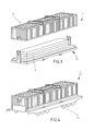
- FIG. 3 shows the device 1 again with lifted from the bottom 2 hood 3, in which case three arranged on the bottom 2 slabs 4 are shown, which are received in the device 1.
- the shots of the bottom 2 are dimensioned accordingly so that they - in addition to the weight of the bottom 2 and the weight of the hood 3 - also record and remove the weight of the three stacked slabs 4.
- the floor 3 is structured such that it can receive and remove the said weights, without requiring separate support of the floor 3.
- FIG. 4 shows schematically the device 1 when transported on a schematically indicated railway wagon 5.
- the device 1 is also used for transport on other, in the field of steel production Transport and lifting means suitable because the transport and lifting means by the design of the bottom 2 no own support of recorded in the device 1 slabs must provide.
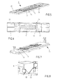
- FIGS. 5 and 6 schematically the bottom 2 of the device 1 with corresponding longitudinal members 20 and cross members 22 is shown.
- the longitudinal members 20 and cross member 22 are formed so that they form the respective receptacles for receiving and removing at least the total weight of the bottom 2, the hood 3, as well as recorded on the bottom 2 slabs 4.
- the side members 20 and the cross member 22 are dimensioned so that a deflection of the bottom 2 does not occur appreciably even at full load of the device 1 and according to the recordings forming longitudinal beams 20 and cross members 22 slabs safely and without distortion or deformation of the Floor 2 can be supported.
- the cross member 22 have in their extension stops 24, which serve for coupling a lifting device, such as a crane. At the stops 24, the bottom 2 can be lifted together with the hood shown in the preceding figures and the slabs 4 received therein via a corresponding lifting device and be relocated to another means of transport, or stored in a warehouse, preferably stacked, are.
- the structure, dimensioning and design of the floor 2 differs from those known in the prior art, inter alia, in that supporting the floor 2 at several points or areas, for example by a roller conveyor, is not necessary, but rather the device 1, for example at the stops 24 without losing their structural integrity.
- FIG. 6 is schematically in a plan view the in FIG. 5 shown frame structure, wherein schematically a large slab 4 and darker hatched - a smallest recordable slab 4 'are recorded in their dimensions.
- the large slab 4 is both on the longitudinal members 20 and on the cross members 22, a smallest slab 4 ', however, only on the longitudinal members 20.
- the distances between the cross members 22 and the longitudinal members 20 are designed accordingly that all in slabs produced on the respective continuous casting plant can be accommodated on the floor 2 so that the respective slabs 4, 4 'can be supported correspondingly via the receptacles, for example in the form of the crossbeams 22 and longitudinal members 20.
- the device Since an essential aspect of the proposed device 1 is to achieve a particularly good insulation of the heat energy absorbed in the slabs 4, 4 'relative to the outside and to correspondingly reduce the energy loss, the device is correspondingly thermally insulated.
- FIGS. 7 and 8 shown the ground 2 in the area through the in FIG. 5 shown longitudinal members 20 and cross member 22, which act as recordings, with corresponding, high strength insulation 6 in the form of refractory bricks, preferably based on silicate, occupied.
- the slabs as in FIG. 6 shown, are placed on the refractory bricks 6 so that the corresponding weight of the slabs rests directly on the longitudinal members 20 and cross members 22 and is correspondingly removed into the structure of the bottom 2.
- a further insulation against the radiant heat of the soil is achieved via an introduced between the refractory bricks 6 Blumbleton sectionung 60, by means of which the bottom 2 is insulated towards the bottom.
- FIGS. 5 and 6 shown further frame members 26 which surround the longitudinal members 20 and cross member 22, serve to accommodate insulating elements, which are necessary for a complete shield, and continue to serve as a receptacle for ablating the registered through the hood 3 loads and transfer to the receptacles 20, 22.
- the refractory bricks 6 are preferably slightly above the Blähton sectionung 60 out, so that a direct contact of the respective slab underside with the Blähton sectionung 60 does not take place.
- FIG. 8 schematically shows an exemplary arrangement of the refractory bricks 6 on the cross members 22, wherein 6 anchors corresponding to the anchoring of the refractory bricks 62 are positioned on the cross members 22, by means of which the refractory bricks 6 can be held in position.
- About the material thickness of the armature 62 is in the in FIG. 8 embodiment shown also further provided an expansion joint between the individual refractory bricks 6, so that different temperatures of the refractory bricks 6 does not lead to excessive stress on the refractory material.
- the insulation in the form of refractory bricks 6, the Blähton sectionung 60, as well as the insulation elements 62 may be formed for quick change or refilling in case of wear.
- the insulation elements 62 are either hung on the hood 3 or can be quickly replaced via detachable connections.
- the refractory bricks 6 can also be easily lifted out of the anchors 62 shown and replaced with new refractory bricks.
- FIGS. 9 and 10 schematically the construction of the hood 3 is shown, which according to FIG. 9 consists of a support structure 30, which with, as from FIG. 10 can be seen, walls, for example, trapezoidal sheets 32 is filled.
- stops 34 which serve to lift the hood 3 by means of a crane or other lifting device of the bottom 2 to allow filling or emptying of the device 1.
- the stops 34 may also serve, with a suitable dimensioning, to raise the hood 3 together with the bottom 2 and the slabs set up on the bottom 2.
- receptacles 36 are provided in addition to the stop 34, which serve to receive the weight of another device 1 and remove.
- the support structure 30 of the hood 3 is correspondingly dimensioned so that a lifting of the device 1 on the stop 34 and / or a settling of a further device 1 on the receptacles 36 on an already loaded device 1 is possible.
- the frame structure 30 and the walls 32 are lined with Isoliermodulen 64, wherein, as shown in the detailed illustration, the individual Isoliermodule 64 are connected via anchors 66 with the corresponding support structure 30 and the trapezoidal sheets 32.
- a transverse plate 68 attached to the lowermost insulating module 64 is provided, by means of which the individual insulating modules 64 of a wall are prevented from slipping off.
- 2 guide means 70 are provided on the bottom, in which complementary guide means 72 engage the hood 3. Accordingly, when lowering the hood 3 to the floor 2, the guide means 72 provided on the hood is guided in the guide means 70 provided on the floor 2 in such a way that a precise and precisely aligned placing of the hood 3 on the floor 2 is achieved.
- the hood 3 can still be locked to the bottom 2.
- this lock is then designed so that the entire device 2 can be completely raised over the stop 34, so both the hood 3 and the bottom 2 can be raised with a possibly recorded thereon slab on the cover 34 provided on the hood 3 ,
- the device 1 Due to the construction shown and in particular the corresponding design of the images of the bottom 2 ensures that the device 1 is very flexible and can be transported on roller skates due to the flat bottom of the shots forming longitudinal supports 20 and cross member. About the stops 24, 34 but the device 1 can also be raised in lifting devices, such as cranes, and then in a simple manner to a heavy-load low loader or the example in FIG. 4 shown railroad car 5 are implemented. Furthermore, the stackability of the individual devices is such that two or more of the insulating boxes shown can be stacked one above the other.
- the content of the device 1 can preferably be identified via corresponding identification means.
- identification means for example, offer RFID transponder or other means of identification, which can be detected automatically.
- the insulation box described can be operated with optimally short open times, since it can be opened and closed at the appropriate intended processing locations. Due to the corresponding design of the floor, the insulating box can be placed directly on the continuous casting plant so that the finished cast slab can be directly absorbed, and on the other hand, the Isolierbox due to the structural design of the Soil can be lifted directly to the beginning of the hot rolling mill, whereby the actual open times can be kept short.
- the insulating box is self-sufficient in that it requires no additional power supply or power supply, but acts as a passive element. It can be used accordingly without blocking transport or lifting capacity as a buffer for decoupling the workflow between continuous casting and hot rolling mill.
- it is also stackable, taking advantage of the available storage space almost as well as uninsulated boxes. The stackability makes it a slightly larger volume immediately.
- the insulation box makes a significant contribution to reducing the environmental impact in this context.
Landscapes
- Engineering & Computer Science (AREA)
- Mechanical Engineering (AREA)
- Furnace Housings, Linings, Walls, And Ceilings (AREA)
- Loading Or Unloading Of Vehicles (AREA)
- Heat Treatments In General, Especially Conveying And Cooling (AREA)
Description
- Die vorliegende Erfindung betrifft eine Vorrichtung zum Transportieren mindestens einer Bramme, bevorzugt mindestens einer aus einer Stranggießanlage austretenden Bramme.
- In Stranggießanlagen werden die Stranggießprodukte üblicherweise so erzeugt, dass sie beim Verlassen der jeweiligen Anlage noch einen sehr großen Wärmegehalt haben. Typischerweise beträgt die mittlere Temperatur einer Bramme beim Verlassen einer Stranggießanlage noch etwa 1000°C. Die Brammen - beziehungsweise andere Stranggießprodukte, wie Knüppel, Stangen etc. - werden dann meist in Lager verbracht, in denen sie bis zur Weiterverarbeitung in einem Walzwerk zur Herstellung eines fertiggewalzten Produktes zwischengelagert werden. Während dieses Lagerprozesses kühlen die Brammen üblicherweise stark ab und können dabei sogar Umgebungstemperatur erreichen. Um im Walzprozess verarbeitet zu werden, müssen die Brammen dann erneut auf die Arbeitstemperatur des Walzvorgangs erhitzt werden, welche typischerweise bei 1200°C liegt. Entsprechend ist ein hoher Energieeinsatz notwendig, um die abgekühlten Brammen aus dem Brammenlager wieder auf Warmwalzprozesstemperatur zu bringen. Hierdurch entstehen hohe Kosten und die Umweltverträglichkeit eines entsprechenden Prozesses leidet.
- Entsprechend ist es aus dem Stand der Technik bekannt, Isolationswärmehauben bereitzustellen, welche für den Transport der Brammen von der Stranggießanlage zu einer Walzstraße verwendet werden. Eine entsprechende Einrichtung zum Warmhalten von aus einer Stranggießanlage austretenden Brammen ist beispielsweise aus der
WO 2008/025325 A1 bekannt. Die Brammen werden hier in den entsprechenden geschlossenen Behältern über Rollgänge transportiert und dann vor dem Warmwalzwerk den Behältern wieder entnommen. - In einer Alternative ist es bekannt, die Rollgänge, auf welchen Stranggießprodukte geführt werden, mittels entsprechenden Isolationen abzuschirmen. Eine entsprechende Wärmeabschirmungsanordnung ist beispielsweise aus der
EP 0 042 652 A1 bekannt. - Die genannten Isolationsvorrichtungen aus dem Stand der Technik sind dahingehend beschränkt, dass sie jeweils an ein bestimmtes Transportmittel gebunden sind, beispielsweise an das Vorhandensein von Rollengängen oder an Eisenbahnwaggons oder Transportanhänger mit isolierten Böden.
- Ausgehend von dem bekannten Stand der Technik ist es eine Aufgabe der vorliegenden Erfindung, eine Vorrichtung zum Transportieren mindestens einer Bramme anzugeben, welche flexibler eingesetzt werden kann.
- Die genannte Aufgabe wird durch eine Vorrichtung zum Transportieren mindestens einer Bramme mit den Merkmalen des Anspruchs 1 gelöst.
- Entsprechend umfasst die Vorrichtung zum Transportieren mindestens einer Bramme einen Boden zur Aufnahme der mindestens einen Bramme und eine auf den Boden aufsetzbare Haube. Erfindungsgemäß weist der Boden mindestens eine Aufnahme zum Aufnehmen und Abtragen zumindest des Gesamtgewichts der Haube und der auf dem Boden aufgenommenen mindestens einen Bramme auf.
- Dadurch, dass der Boden der Vorrichtung die genannten Aufnahmen zum Aufnehmen und Abtragen zumindest des Gesamtgewichts der Haube und der auf dem Boden aufgenommenen mindestens eine Bramme aufweist, ist die Vorrichtung zum Transportieren sehr flexibel in Bezug auf das verwendete Transportmittel. Insbesondere kann sie neben der Verwendung auf Rollengängen, bei welchen ein Abtragen des Gesamtgewichtes der Vorrichtung über den Boden im Prinzip keine Rolle spielt, da das Gesamtgewicht von den Rollen des Rollenganges getragen wird, auch beispielsweise über die in Stahlwerken üblichen Hebevorrichtungen, wie beispielsweise Hebekräne, mitsamt dem Inhalt angehoben und umgesetzt werden. Darüber hinaus wird es auf diese Weise möglich, die Vorrichtung auf einen Schwerlasttieflader oder einen Eisenbahnwaggon beziehungsweise ein Eisenbahngestell umzusetzen, um auf diese Weise ein flexibles Transportieren der jeweiligen Bramme zu erreichen.
- Besonders bevorzugt ist die Vorrichtung auch selbsttragend ausgebildet, so dass sich auch der Boden selbst tragen kann. Mit anderen Worten kann über die Aufnahmen neben dem Gesamtgewicht der Haube und der auf den Aufnahmen aufgelegten Brammen auch das Eigengewicht des Bodens aufgenommen werden, so dass die Vorrichtung auf den unterschiedlichsten Transportmitteln transportiert werden kann, ohne strukturell beschädigt zu werden.
- Die Vorrichtung ist bevorzugt so dimensioniert, dass mindestens zwei Brammen übereinander auf der mindestens einen Aufnahme stapelbar sind. Damit kann die Effizienz der Vorrichtung noch weiter gesteigert werden, da unter anderem auch die in die Vorrichtung eingetragene Wärmemenge höher ist und damit die Brammen noch länger warm gehalten werden können. Auf diese Weise lässt sich auch erreichen, dass ein langsamerer Abfall der Wärme in den aufeinander gestapelten Brammen erreicht werden kann, als beim Transport einer einzelnen Bramme.
- Um ein besonders einfaches Heben und Transportieren zu erreichen, weist die Haube mindestens ein Abtragmittel zum Abtragen des Gewichts mindestens einer auf der Haube gestapelten weiteren Vorrichtung auf, wobei das mindestens eine Abtragmittel das Gewicht auf den Boden der unteren Vorrichtung abträgt. Auf diese Weise wird es auch möglich, die vorgeschlagene Vorrichtung zum Transportieren von Brammen so einzusetzen, dass sie gestapelt werden kann und entsprechend in einem Brammenlager die notwendige Grundfläche verringert werden kann oder auf einer gegebenen Grundfläche eine höhere Anzahl an Brammen zwischengelagert werden kann. Dies wird im Übrigen auch dadurch erreicht, dass mindestens zwei Brammen übereinander gestapelt in einer einzelnen Vorrichtung zum Transportieren aufgenommen werden können.
- Bevorzugt ist die Vorrichtung kompatibel zu üblicherweise in Stahlwerken verwendeten Transport- und Hebemitteln, bevorzugt zu Schwerlasttiefladern, Eisenbahnwaggons, Rollgängen sowie Kränen und anderen Hubvorrichtungen, wobei besonders bevorzugt die Haube und/oder der Boden der Vorrichtung entsprechende Anschlagvorrichtungen für Kran- und Hebevorrichtungen aufweist. Auf diese Weise kann ein einfaches Handling mit den vorhandenen Transport- und Hebevorrichtungen in einem Stahlwerk erreicht werden, beispielsweise mit den vorhandenen Tiefladern, Eisenbahnwaggons sowie Kranvorrichtungen, welche dann sämtlich in Verbindung mit vorhandenen Rollgängen zum Handling der jeweiligen Vorrichtungen verwendet werden können.
- Insbesondere ist der Boden besonders bevorzugt so ausgestaltet, dass er auf Rollgängen verwendet werden kann. Bevorzugt ist er an seiner Unterseite ausreichend plan, um entsprechend über die Rollgänge geführt zu werden.
- Die Haube ist bevorzugt über Verriegelungsmittel mit dem Boden so verbindbar, dass Boden, Haube und die auf dem Boden aufgenommene Bramme beziehungsweise die aufgenommenen Brammen über ein an der Haube angeordnetes Anschlagmittel angehoben werden können. Auch hierdurch lässt sich das Handling der Vorrichtung deutlich vereinfachen, da eine entsprechende Hubvorrichtung lediglich auf der Oberseite der Haube angeschlagen werden muss.
- Bevorzugt weist die Haube und/oder der Boden Führungsmittel zum Führen der Haube in ihre Aufsetzposition beziehungsweise Verriegelungsposition auf dem Boden auf. So kann ein einfaches Abheben und erneutes Aufsetzen der Haube auf den Boden erreicht werden, um ein Beladen des Bodens mit Brammen zu ermöglichen und danach ein schnelles und einfaches Verschließen zu erreichen.
- Bevorzugt weisen die Aufnahmen des Bodens Längsträger und/oder Querträger auf, wobei besonders bevorzugt eine Isolierung hoher Festigkeit auf den Aufnahmen aufgebracht ist. Hierzu eignen sich besonders bevorzugt Feuerfeststeine, bevorzugt auf Silikatbasis, welche auf den entsprechenden Aufnahmen so aufgebracht werden, dass die Brammen auf den entsprechenden Feuerfeststeinen aufgelegt werden können und die durch die Brammen eingetragenen Lasten direkt auf den Aufnahmen des Bodens abgetragen werden. Hierdurch lässt sich auf der einen Seite eine bevorzugte Isolierung erreichen, auf der anderen Seite ermöglicht das Vorsehen der Aufnahmen im Boden eine sichere und plane Auflage für die Brammen während des Transportes und der Lagerung. Die Feuerfeststeine sind bevorzugt über Anker auf den Aufnahmen positioniert.
- Bevorzugt wird die Anzahl der Feuerfeststeine auf die Zahl begrenzt, die für das sichere Abtragen des eingesetzten Brammengewichts erforderlich ist.
- Eine weitere Isolierung des Bodens, insbesondere zwischen den Aufnahmen beziehungsweise zwischen auf den Aufnahmen aufgelegten Feuerfeststeinen, kann mit Vorteil über eine Blähtonschüttung erreicht werden, welche im Boden aufgenommen ist.
- Die Haube weist bevorzugt eine Trägerkonstruktion auf, an welcher mit Vorteil Wandelemente angebracht sind, die mit Isoliermaterialien ausgekleidet sind.
- Bevorzugt kann die Isolation auch mehrlagig ausgeführt sein.
- In einer weiteren bevorzugten Ausgestaltung weist die Vorrichtung Identifikationsmittel zur Identifikation des auf dem Boden aufgenommenen Inhalts auf, so dass eine weitgehend automatisierte Logistik angewendet werden kann.
- Bevorzugte weitere Ausführungsformen und Aspekte der vorliegenden Erfindung werden durch die nachfolgende Beschreibung der Figur näher erläutert. Dabei zeigen
- Figur 1
- schematisch eine Vorrichtung zum Transportieren mindestens einer Bramme mit einem Boden und einer Haube in einer perspektivischen Ansicht im geöffneten Zustand;
- Figur 2
- die in
Figur 1 gezeigte Vorrichtung perspektivisch im geschlossenen Zustand; - Figur 3
- die in den
Figuren 1 und 2 gezeigte Vorrichtung im geöffneten Zustand und mit drei Brammen beladen; - Figur 4
- die in den
Figuren 1 bis 3 gezeigte Vorrichtung schematisch auf einen Eisenbahnwaggon geladen; - Figur 5
- schematisch eine Struktur des Bodens in einer schematischen perspektivischen Ansicht;
- Figur 6
- den Boden der
Figur 5 in einer schematischen Draufsicht; - Figur 7
- den Boden der
Figur 5 mit Isolationsmaterial ausgestattet; - Figur 8
- eine schematische Detailansicht einer Verankerung des Isolationsmaterials;
- Figur 9
- eine schematische Konstruktion einer Rahmenkonstruktion der Haube;
- Figur 10
- die Haube mit Wandelementen ausgestattet; und
- Figur 11
- einen schematischen Querschnitt durch die Haube mit den entsprechenden Isolationsmaterialien.
- Im Folgenden werden bevorzugte Ausführungsbeispiele anhand der Figuren beschrieben. Dabei werden gleiche, ähnliche oder gleichwirkende Elemente in den unterschiedlichen Figuren mit identischen Bezugszeichen bezeichnet und auf eine wiederholte Beschreibung dieser Elemente wird in der nachfolgenden Beschreibung teilweise verzichtet, um Redundanzen zu vermeiden.
-
Figur 1 zeigt eine Vorrichtung 1 zum Transport mindestens einer in dieser Figur nicht gezeigten Bramme, wobei die Vorrichtung 1 einen Boden 2 und eine auf den Boden 2 aufsetzbare Haube 3 umfasst. In den weiterenFiguren 2 bis 11 werden unterschiedliche Aspekte und Details der vorgeschlagenen Vorrichtung 1 gezeigt. - Der Boden 2 der Vorrichtung 1 weist beispielsweise in den
Figuren 5 und 6 detailliert gezeigte Aufnahmen zum Aufnehmen und Abtragen zumindest des Gesamtgewichts der Haube 3 und der auf den Boden 2 aufgelegten und in denFiguren 1 und 2 nicht gezeigten Brammen auf. Der Boden 2 beziehungsweise die Aufnahmen sind dabei auch selbsttragend ausgebildet. Mit anderen Worten kann über die Aufnahmen neben dem Gesamtgewicht der Haube 3 und der auf den Aufnahmen aufgelegten Brammen auch das Eigengewicht des Bodens 2 aufgenommen werden. Die gesamte Vorrichtung 1 ist damit selbsttragend ausgebildet. - Die Haube 3 ist in dem in der
Figur 1 gezeigten Zustand vom Boden 2 abgehoben, so dass die leere Vorrichtung 1 geöffnet gezeigt ist. -
Figur 2 zeigt in einer schematischen perspektivischen Ansicht die Vorrichtung 1 in einem verschlossenen Zustand, nämlich bei auf dem Boden 2 aufgesetzter Haube 3. Der inFigur 2 gezeigte Zustand ist der zum Transportieren der Bramme verwendete und geeignete Zustand. -
Figur 3 zeigt die Vorrichtung 1 erneut mit vom Boden 2 abgehobener Haube 3, wobei hier drei auf dem Boden 2 angeordnete Brammen 4 gezeigt sind, welche in der Vorrichtung 1 aufgenommen sind. Die Aufnahmen des Bodens 2 sind entsprechend derart dimensioniert, dass sie - neben dem Eigengewicht des Bodens 2 und dem Gewicht der Haube 3 - auch das Gewicht der drei übereinander gestapelten Brammen 4 aufnehmen und abtragen können. Mit anderen Worten ist der Boden 3 derart strukturiert, dass er die genannten Gewichte aufnehmen und abtragen kann, ohne dass es einer separaten Unterstützung des Bodens 3 bedürfte. In herkömmlichen Vorrichtungen zum Transport von Brammen war es notwendig, dass der Boden separat unterstützt wird, um die jeweiligen Gewichte abtragen zu können. Dies wurde beispielsweise durch eine Rollenbahn erreicht, auf welcher die entsprechende -
Figur 4 zeigt schematisch die Vorrichtung 1 bei einem Transport auf einem schematisch angedeuteten Eisenbahnwaggon 5. Die Vorrichtung 1 ist aber auch zum Transport auf anderen, im Bereich der Stahlherstellung verwendeten Transport- und Hebemitteln geeignet, da die Transport- und Hebemittel durch die Auslegung des Bodens 2 keine eigene Unterstützung der in der Vorrichtung 1 aufgenommenen Brammen bereit stellen müssen. - In den
Figuren 5 und 6 ist schematisch der Boden 2 der Vorrichtung 1 mit entsprechenden Längsträgern 20 und Querträgern 22 gezeigt. Die Längsträger 20 und Querträger 22 sind dabei so ausgebildet, dass sie die jeweiligen Aufnahmen zum Aufnehmen und Abtragen zumindest des Gesamtgewichts des Bodens 2, der Haube 3, sowie der auf dem Boden 2 aufgenommenen Brammen 4 ausbilden. Entsprechend sind die Längsträger 20 und die Querträger 22 so dimensioniert, dass eine Durchbiegung des Bodens 2 auch bei voller Beladung der Vorrichtung 1 nicht nennenswert auftritt und entsprechend die auf den die Aufnahmen ausbildenden Längsträgern 20 und Querträgern 22 aufliegenden Brammen sicher und ohne Verwindung beziehungsweise Verformung des Bodens 2 gestützt werden können. Die Querträger 22 weisen in ihrer Verlängerung Anschläge 24 auf, welche zum Ankoppeln einer Hubvorrichtung, beispielsweise eines Krans, dienen. An den Anschlägen 24 kann der Boden 2 mitsamt der in den vorhergehenden Figuren gezeigten Haube und den darin aufgenommenen Brammen 4 über eine entsprechende Hubvorrichtung angehoben werden und entsprechend auf ein anderes Transportmittel umgelagert werden, oder in eine Lager gelagert, bevorzugt gestapelt, werden. - Entsprechend unterscheidet sich die Struktur, Dimensionierung und Auslegung des Bodens 2 gegenüber den im Stand der Technik bekannten unter anderem dahingehend, dass eine an mehreren Punkten beziehungsweise Bereichen aufliegende Unterstützung des Bodens 2, beispielsweise durch eine Rollenbahn, nicht notwendig ist, sondern die Vorrichtung 1 beispielsweise an den Anschlägen 24 angehoben werden kann, ohne ihre strukturelle Integrität zu verlieren.
- In
Figur 6 ist schematisch in einer Draufsicht die inFigur 5 gezeigte Rahmenkonstruktion gezeigt, wobei schematisch eine große Bramme 4 sowie - dunkler schraffiert - eine kleinste aufzunehmende Bramme 4' in ihren Dimensionen aufgezeichnet sind. Entsprechend liegt die große Bramme 4 sowohl auf den Längsträgern 20 als auch auf den Querträgern 22 auf, eine kleinste Bramme 4' hingegen jedoch nur auf den Längsträgern 20. Die Abstände zwischen den Querträgern 22 und den Längsträgern 20 sind entsprechend so ausgebildet, dass sämtliche in der jeweiligen Stranggießanlage hergestellten Brammen auf dem Boden 2 so aufgenommen werden können, dass die jeweiligen Brammen 4, 4' über die Aufnahmen, beispielsweise in Form der Querträger 22 und Längsträger 20, entsprechend abgestützt werden können. - Da ein wesentlicher Aspekt der vorgeschlagenen Vorrichtung 1 darin liegt, eine besonders gute Isolierung der in den Brammen 4, 4' aufgenommenen Wärmeenergie gegenüber der Außenseite zu erreichen und entsprechend den Energieverlust zu reduzieren, ist die Vorrichtung entsprechend wärmeisoliert. Dazu ist, wie in
Figuren 7 und 8 gezeigt, der Boden 2 im Bereich der durch die inFigur 5 gezeigten Längsträger 20 und Querträger 22, welche als Aufnahmen fungieren, mit entsprechenden, hohe Festigkeit aufweisenden Isolierungen 6 in Form von Feuerfeststeinen, bevorzugt auf Silikatbasis, belegt. Entsprechend können die Brammen, so wie inFigur 6 gezeigt, auf die Feuerfeststeine 6 so aufgelegt werden, dass das entsprechende Gewicht der Brammen direkt auf den Längsträgern 20 und Querträgern 22 aufliegt und entsprechend in die Struktur des Bodens 2 abgetragen wird. Über die Feuerfeststeine 6 wird dabei eine sehr gute Isolierung der Bramme von den entsprechenden Aufnahmen 20, 22 erreicht. - Eine weitere Isolierung gegen die Strahlungshitze des Bodens wird über eine zwischen den Feuerfeststeinen 6 eingebrachte Blähtonschüttung 60 erreicht, mittels welcher der Boden 2 nach unten hin isoliert wird.
- Die in den
Figuren 5 und 6 gezeigten weiteren Rahmenelemente 26, welche die Längsträger 20 und Querträger 22 umgeben, dienen dazu, Isolierelemente aufzunehmen, welche für eine vollständige Abschirmung notwendig sind, und dienen weiterhin als Aufnahme dafür, die durch die Haube 3 eingetragenen Lasten abzutragen und auf die Aufnahmen 20, 22 zu übertragen. - Wie in
Figur 7 gezeigt, stehen die Feuerfeststeine 6 bevorzugt etwas über die Blähtonschüttung 60 heraus, so dass ein direkter Kontakt der jeweiligen Brammenunterseite mit der Blähtonschüttung 60 nicht stattfindet. -
Figur 8 zeigt schematisch eine exemplarische Anordnung der Feuerfeststeine 6 auf den Querträgern 22, wobei hier zur Verankerung der Feuerfeststeine 6 entsprechende Anker 62 auf den Querträgern 22 positioniert sind, mittels welchen die Feuerfeststeine 6 in ihrer Position gehalten werden können. Über die Materialstärke der Anker 62 wird in der inFigur 8 gezeigten Ausführungsform weiterhin auch eine Dehnungsfuge zwischen den einzelnen Feuerfeststeinen 6 bereitgestellt, so dass unterschiedliche Temperaturen der Feuerfeststeine 6 nicht zu übermäßiger Beanspruchung des Feuerfestmaterials führt. - Die Isolierungen in Form der Feuerfeststeine 6, der Blähtonschüttung 60, sowie der Isolationselemente 62 können zum schnellen Wechsel beziehungsweise zum Nachfüllen bei Verschleiß ausgebildet sein. Dazu sind die Isolationselemente 62 an der Haube 3 entweder eingehängt oder können über lösbare Verbindungen schnell ausgetauscht werden.
- Die Feuerfeststeine 6 können ebenfalls einfach aus den gezeigten Ankern 62 herausgehoben werden und durch neue Feuerfeststeine ersetzt werden.
- In den
Figuren 9 und 10 ist schematisch die Konstruktion der Haube 3 gezeigt, welche gemäßFigur 9 aus einer Trägerkonstruktion 30 besteht, welche mit, wie ausFigur 10 zu erkennen ist, Wänden, beispielsweise aus Trapezblechen 32 ausgefüllt ist. - Auf der Oberseite sind entsprechende Anschläge 34 vorgesehen, welche dazu dienen, die Haube 3 mittels eines Kranes oder einer anderen Hubvorrichtung von dem Boden 2 abzuheben, um eine Befüllung oder Entleerung der Vorrichtung 1 zu ermöglichen. Die Anschläge 34 können bei einer geeigneten Dimensionierung auch dazu dienen, die Haube 3 mitsamt dem Boden 2 und den auf dem Boden 2 aufgelegten Brammen anzuheben.
- Weiterhin sind neben dem Anschlag 34 auch Aufnahmen 36 vorgesehen, welche dazu dienen, das Gewicht einer weiteren Vorrichtung 1 aufzunehmen und abzutragen. Mit anderen Worten können zwei der oben beschriebenen Vorrichtungen - beispielsweise in
Figur 2 gezeigten Art - übereinander gestapelt werden. Die Trägerkonstruktion 30 der Haube 3 ist entsprechend so dimensioniert, dass ein Anheben der Vorrichtung 1 an dem Anschlag 34 und/oder ein Absetzen einer weiteren Vorrichtung 1 auf den Aufnahmen 36 auf einer bereits beladenen Vorrichtung 1 möglich ist. - Um auch eine ausreichende Isolierung der Haube 3 bereitzustellen, sind die Rahmenkonstruktion 30 sowie die Wände 32 mit Isoliermodulen 64 ausgekleidet, wobei, wie in der Detaildarstellung gezeigt, die einzelnen Isoliermodule 64 über Anker 66 mit der entsprechenden Trägerkonstruktion 30 beziehungsweise den Trapezblechen 32 verbunden sind. Bevorzugt ist ein am untersten Isoliermodul 64 angebrachtes Querblech 68 vorgesehen, mittels welchem die einzelnen Isoliermodule 64 einer Wand am Herunterrutschen gehindert werden.
- Um ein einfaches Aufsetzen der Haube 3 auf den Boden 2 zu ermöglichen, sind am Boden 2 Führungsmittel 70 vorgesehen, in welche dazu komplementäre Führungsmittel 72 an der Haube 3 eingreifen. Entsprechend wird beim Absenken der Haube 3 auf den Boden 2 die an der Haube vorgesehene Führungsmittel 72 in der am Boden 2 vorgesehenen Führungsmittel 70 so geführt, dass ein zielgenaues und exakt ausgerichtetes Platzieren der Haube 3 auf dem Boden 2 erreicht wird.
- Über nicht gezeigte Verriegelungsmittel kann weiterhin die Haube 3 am Boden 2 verriegelt werden. Bevorzugt ist diese Verriegelung dann so ausgebildet, dass die gesamte Vorrichtung 2 über den Anschlag 34 komplett angehoben werden kann, also über den an der Haube 3 vorgesehenen Anschlag 34 sowohl die Haube 3 als auch der Boden 2 mit einer möglicherweise darauf aufgenommenen Bramme angehoben werden kann.
- Durch die gezeigte Konstruktion und insbesondere die entsprechende Auslegung der Aufnahmen des Bodens 2 wird erreicht, dass die Vorrichtung 1 sehr flexibel einsetzbar ist und aufgrund der flachen Unterseite der die Aufnahmen ausbildenden Längsträger 20 und Querträger 22 auf Rollgängen transportiert werden kann. Über die Anschläge 24, 34 kann die Vorrichtung 1 aber auch in Hubvorrichtungen, wie beispielsweise Kränen, angehoben werden und dann entsprechend auf einfache Weise auf einen Schwerlasttieflader oder den beispielhaft in
Figur 4 gezeigten Eisenbahnwaggon 5 umgesetzt werden. Weiterhin ergibt sich eine Stapelfähigkeit der einzelnen Vorrichtungen derart, dass zwei oder mehrere der gezeigten Isolierboxen übereinander gestapelt werden können. - Der Inhalt der Vorrichtung 1 kann bevorzugt über entsprechende Identifikationsmittel identifiziert werden. Hierzu bieten sich beispielsweise RFID-Transponder oder andere Identifikationsmittel an, welche automatisch erkannt werden können.
- Die beschriebene Isolierbox kann mit optimal kurzen Offenzeiten betrieben werden, da sie an den entsprechenden vorgesehenen Verarbeitungsorten geöffnet und verschlossen werden kann. Durch die entsprechende Auslegung des Bodens kann die Isolierbox nämlich zum einen direkt an der Stranggießanlage so platziert werden, dass die fertig gegossene Bramme direkt aufgenommen werden kann, und zum anderen kann die Isolierbox aufgrund der strukturellen Auslegung des Bodens direkt zum Beginn der Warmwalzstraße angehoben werden, wodurch die eigentlichen Offenzeiten kurz gehalten werden können.
- Weiterhin ist die Isolierbox dahingehend autark, dass sie keine zusätzliche Stromversorgung oder Energieversorgung benötigt, sondern als passives Element wirkt. Sie kann entsprechend ohne Blockierung von Transport- oder Hebekapazitäten als Puffer zur Entkopplung der Arbeitsabläufe zwischen Stranggießanlage und Warmwalzwerk genutzt werden. Insbesondere ist sie auch stapelfähig und nutzt dabei den verfügbaren Lagerplatz nahezu so gut aus, wie nicht isolierte Boxen. Durch die Stapelfähigkeit macht sie ein etwas größeres Volumen sofort wett.
- Dadurch leistet die Isolierbox einen signifikanten Beitrag zur Reduzierung der Umweltbelastung in diesem Zusammenhang.
- Soweit anwendbar, können alle einzelnen Merkmale, die in den einzelnen Ausführungsbeispielen dargestellt sind, miteinander kombiniert und/oder ausgetauscht werden, ohne den Bereich der Erfindung zu verlassen.
-
- 1
- Vorrichtung zum Transportieren mindestens einer Bramme
- 2
- Boden
- 20
- Längsträger
- 22
- Querträger
- 24
- Anschlag
- 26
- Rahmenelement
- 3
- Haube
- 30
- Trägerkonstruktion
- 32
- Trapezblech
- 34
- Anschlag
- 36
- Aufnahme
- 4
- Bramme
- 4'
- kleinste Bramme
- 5
- Eisenbahnwaggon
- 6
- Feuerfeststein
- 60
- Blähtonschüttung
- 62
- Anker
- 64
- Isoliermodul
- 66
- Anker
- 68
- Querblech
- 70
- Führungsmittel
- 72
- Führungsmittel
Claims (15)
- Vorrichtung (1) zum Transportieren mindestens einer Bramme (4), umfassend einen Boden (2) zur Aufnahme der mindestens einen Bramme und eine auf den Boden (2) aufsetzbare Haube (3),
dadurch gekennzeichnet, dass
der Boden (2) mindestens eine Aufnahme (20, 22) zum Aufnehmen und Abtragen zumindest des Gesamtgewichts der Haube (3) und der auf dem Boden aufgenommenen mindestens einen Bramme (4) aufweist. - Vorrichtung (1) gemäß Anspruch 1, dadurch gekennzeichnet, dass mindestens zwei Brammen (4) übereinander auf der mindestens einen Aufnahme (20, 22) stapelbar sind.
- Vorrichtung (1) gemäß Anspruch 1 oder 2, dadurch gekennzeichnet, dass die Haube (3) mindestens eine Aufnahme (36) zum Abtragen des Gewichts mindestens einer auf der Haube (3) gestapelten weiteren Vorrichtung (1) aufweist, wobei die mindestens eine Aufnahme (36) das Gewicht auf den Boden (2) der unteren Vorrichtung (1) abträgt.
- Vorrichtung (1) gemäß einem der vorstehenden Ansprüche, dadurch gekennzeichnet, dass die Vorrichtung (1) zum Transport mit Transport- und Hebemitteln kompatibel ist, bevorzugt zum Transport mit Schwerlasttiefladern, Eisenbahnwaggons, Rollgängen und/oder Kränen.
- Vorrichtung (1) gemäß Anspruch 4, dadurch gekennzeichnet, dass die Haube (3) und/oder der Boden (2) mindestens ein Anschlagmittel (24, 34) zum Anschlagen einer Hub- oder Transportvorrichtung aufweisen.
- Vorrichtung (1) gemäß Anspruch 4 oder 5, dadurch gekennzeichnet, dass der Boden (2) kompatibel zum Transport auf Rollgängen gestaltet ist und die mindestens eine Aufnahme (20, 22) bevorzugt an ihrer Unterseite plan ist und bevorzugt eine plane Ebene ausbildet.
- Vorrichtung (1) gemäß einem der vorstehenden Ansprüche, dadurch gekennzeichnet, dass mindestens ein Führungsmittel (70, 72) zum Führen der Haube (3) in eine mit dem Boden (2) verschlossene Position vorgesehen ist.
- Vorrichtung (1) gemäß einem der vorstehenden Ansprüche, dadurch gekennzeichnet, dass die Haube (3) über mindestens ein Verriegelungsmittel mit dem Boden (2) verbindbar ist, bevorzugt derart, dass der Boden (2), die Haube (3) sowie die mindestens eine darin aufgenommene Bramme (4) über mindestens einen an der Haube (3) abgeordneten Anschlag (34) anhebbar ist.
- Vorrichtung (1) gemäß einem der vorstehenden Ansprüche, dadurch gekennzeichnet, dass die mindestens eine Aufnahme mindestens einen Längsträger (20) und/oder mindestens einen Querträger (22) umfasst.
- Vorrichtung (1) gemäß einem der vorstehenden Ansprüche, dadurch gekennzeichnet, dass mindestens eine Isolierung (6) hoher Festigkeit auf der mindestens einen Aufnahme (20, 22) vorgesehen ist, bevorzugt mindestens ein Feuerfeststein auf Silikatbasis, welcher besonders bevorzugt über mindestens einen Anker (62) auf der Aufnahme (20, 22) gehalten ist.
- Vorrichtung (1) gemäß einem der vorstehenden Ansprüche, dadurch gekennzeichnet, dass der Boden (2) eine flächige Isolierung über eine Blähtonschüttung (60) aufweist.
- Vorrichtung (1) gemäß einem der vorstehenden Ansprüche, dadurch gekennzeichnet, dass die Haube (3) eine Trägerkonstruktion (30) aufweist und die Wände mit Isolationsmaterial (64) belegt sind.
- Vorrichtung (1) gemäß einem der Ansprüche 10 bis 12, dadurch gekennzeichnet, dass die Isolation (6, 60, 62) auswechselbar angeordnet ist.
- Vorrichtung (1) gemäß einem der vorstehenden Ansprüche, dadurch gekennzeichnet, dass Identifikationsmittel zur Identifikation des auf dem Boden (2) aufgenommenen Inhalts vorgesehen sind.
- Vorrichtung (1) gemäß einem der vorstehenden Ansprüche, dadurch gekennzeichnet, dass sie selbsttragend ausgebildet ist.
Applications Claiming Priority (1)
| Application Number | Priority Date | Filing Date | Title |
|---|---|---|---|
| DE201210215769 DE102012215769A1 (de) | 2012-09-05 | 2012-09-05 | Heiße Kiste |
Publications (3)
| Publication Number | Publication Date |
|---|---|
| EP2705911A2 true EP2705911A2 (de) | 2014-03-12 |
| EP2705911A3 EP2705911A3 (de) | 2014-06-18 |
| EP2705911B1 EP2705911B1 (de) | 2018-09-26 |
Family
ID=48875515
Family Applications (1)
| Application Number | Title | Priority Date | Filing Date |
|---|---|---|---|
| EP13176451.6A Active EP2705911B1 (de) | 2012-09-05 | 2013-07-15 | Brammentransportvorrichtung |
Country Status (2)
| Country | Link |
|---|---|
| EP (1) | EP2705911B1 (de) |
| DE (1) | DE102012215769A1 (de) |
Citations (2)
| Publication number | Priority date | Publication date | Assignee | Title |
|---|---|---|---|---|
| EP0042652A1 (de) | 1980-06-20 | 1981-12-30 | Trefileries De Bourbourg | Verfahren zum Bündeln von Drahtnetzrollen |
| WO2008025325A1 (de) | 2006-09-01 | 2008-03-06 | Sms Demag Ag | Einrichtung zum warmhalten von aus einer stranggiessanlage austretenden brammen |
Family Cites Families (3)
| Publication number | Priority date | Publication date | Assignee | Title |
|---|---|---|---|---|
| TW336184B (en) * | 1995-01-11 | 1998-07-11 | Tippins Inc | Intermediate thickness slab caster and inline hot strip and plate line, method of processing metal slabs and slab container |
| US8002134B2 (en) * | 2006-04-20 | 2011-08-23 | Cakeboxx, Llc | Doorless intermodal cargo container |
| FI121747B (fi) * | 2009-06-12 | 2011-03-31 | Oy Langh Ship Ab | Kuljetusteline |
-
2012
- 2012-09-05 DE DE201210215769 patent/DE102012215769A1/de not_active Withdrawn
-
2013
- 2013-07-15 EP EP13176451.6A patent/EP2705911B1/de active Active
Patent Citations (2)
| Publication number | Priority date | Publication date | Assignee | Title |
|---|---|---|---|---|
| EP0042652A1 (de) | 1980-06-20 | 1981-12-30 | Trefileries De Bourbourg | Verfahren zum Bündeln von Drahtnetzrollen |
| WO2008025325A1 (de) | 2006-09-01 | 2008-03-06 | Sms Demag Ag | Einrichtung zum warmhalten von aus einer stranggiessanlage austretenden brammen |
Also Published As
| Publication number | Publication date |
|---|---|
| EP2705911A3 (de) | 2014-06-18 |
| EP2705911B1 (de) | 2018-09-26 |
| DE102012215769A1 (de) | 2014-03-06 |
Similar Documents
| Publication | Publication Date | Title |
|---|---|---|
| DE602006000358T2 (de) | Anordnung und Verfahren zum Verpacken eines Gestells für Computer, Gestell für Computer und Palette für dieses Gestell | |
| DE102009049563B4 (de) | Shuttle-Kanallager, Shuttle-Bahnhof, Shuttle und Verfahren zum Betreiben des Shuttle-Kanallagers | |
| EP3194232B1 (de) | Güterwaggon mit einem waggonaufsatz, güterumschlagvorrichtung mit derartigen güterwaggons und güterumschlagverfahren | |
| WO2009132687A1 (de) | Shuttle-kanallager, shuttle-bahnhof, shuttle und verfahren zum betreiben des shuttle-kanallagers | |
| WO2008046728A1 (de) | Flurgebundenes transportfahrzeug, insbesondere für den transport von containern | |
| DE102019106033A1 (de) | Regalbediengerät zum Verladen von stapelfähigen Waren und Logistiksystem mit einem solchen Regalbediengerät | |
| AT506918A1 (de) | Aufnahmevorrichtung für ein förderfahrzeug | |
| DE102008007826A1 (de) | Transferfahrzeug, insbesondere im Luftfrachtverkehr, zum Ein- und Auslagern von Stückgutcontainern | |
| DE102017113499A1 (de) | Transportsystem | |
| DE102008052238B4 (de) | Einrichtung zum Transportieren von im Wesentlichen langgestreckten runden Gegenständen | |
| DE102013102778A1 (de) | Regallager mit einem tiefgekühlten und/oder inertisierten Lagerbereich | |
| EP2705911B1 (de) | Brammentransportvorrichtung | |
| DE102008031981A1 (de) | Transportfahrzeug zum Anheben und Transportieren von ULDs und Cargopaletten | |
| EP2261129A1 (de) | Palette zum Transportieren von Gegenständen mittels eines Gabelstaplers | |
| DE102013106722A1 (de) | Hubeinrichtung sowie Entnahmevorrichtung mit einer Hubeinrichtung | |
| EP1696095B1 (de) | Regallagertor | |
| EP3642136B1 (de) | Wechselaufbau | |
| DE202008007269U1 (de) | Palettenlageranlage zur Lagerhaltung von Lagergütern, insbesondere für den Einsatz in Schiffen | |
| EP2106996B1 (de) | Palettenlageranlage zur Lagerhaltung von Lagergütern | |
| DE19733963C2 (de) | Verfahren und Vorrichtung zum Umschlagen von Ladung | |
| DE102024200261B3 (de) | Integration Containerinstandhaltung | |
| DE2931911C3 (de) | Einrichtung zum gesteuerten Abkühlen von Stäben oder Profilen | |
| DE102015107003A1 (de) | Holzhackschnitzeltransportwagen | |
| DE10234310A1 (de) | Ladevorrichtung und Verfahren zum Be- und Entladen eines Güterschiffs | |
| DE102013001484B3 (de) | Transportpalette für Druckgasflaschen |
Legal Events
| Date | Code | Title | Description |
|---|---|---|---|
| PUAI | Public reference made under article 153(3) epc to a published international application that has entered the european phase |
Free format text: ORIGINAL CODE: 0009012 |
|
| 17P | Request for examination filed |
Effective date: 20130715 |
|
| AK | Designated contracting states |
Kind code of ref document: A2 Designated state(s): AL AT BE BG CH CY CZ DE DK EE ES FI FR GB GR HR HU IE IS IT LI LT LU LV MC MK MT NL NO PL PT RO RS SE SI SK SM TR |
|
| AX | Request for extension of the european patent |
Extension state: BA ME |
|
| PUAL | Search report despatched |
Free format text: ORIGINAL CODE: 0009013 |
|
| AK | Designated contracting states |
Kind code of ref document: A3 Designated state(s): AL AT BE BG CH CY CZ DE DK EE ES FI FR GB GR HR HU IE IS IT LI LT LU LV MC MK MT NL NO PL PT RO RS SE SI SK SM TR |
|
| AX | Request for extension of the european patent |
Extension state: BA ME |
|
| RIC1 | Information provided on ipc code assigned before grant |
Ipc: B21B 39/00 20060101AFI20140513BHEP |
|
| 17Q | First examination report despatched |
Effective date: 20141104 |
|
| RBV | Designated contracting states (corrected) |
Designated state(s): AL AT BE BG CH CY CZ DE DK EE ES FI FR GB GR HR HU IE IS IT LI LT LU LV MC MK MT NL NO PL PT RO RS SE SI SK SM TR |
|
| RAP1 | Party data changed (applicant data changed or rights of an application transferred) |
Owner name: SMS GROUP GMBH |
|
| STAA | Information on the status of an ep patent application or granted ep patent |
Free format text: STATUS: EXAMINATION IS IN PROGRESS |
|
| GRAP | Despatch of communication of intention to grant a patent |
Free format text: ORIGINAL CODE: EPIDOSNIGR1 |
|
| STAA | Information on the status of an ep patent application or granted ep patent |
Free format text: STATUS: GRANT OF PATENT IS INTENDED |
|
| INTG | Intention to grant announced |
Effective date: 20180507 |
|
| GRAS | Grant fee paid |
Free format text: ORIGINAL CODE: EPIDOSNIGR3 |
|
| GRAA | (expected) grant |
Free format text: ORIGINAL CODE: 0009210 |
|
| STAA | Information on the status of an ep patent application or granted ep patent |
Free format text: STATUS: THE PATENT HAS BEEN GRANTED |
|
| AK | Designated contracting states |
Kind code of ref document: B1 Designated state(s): AL AT BE BG CH CY CZ DE DK EE ES FI FR GB GR HR HU IE IS IT LI LT LU LV MC MK MT NL NO PL PT RO RS SE SI SK SM TR |
|
| REG | Reference to a national code |
Ref country code: GB Ref legal event code: FG4D Free format text: NOT ENGLISH |
|
| REG | Reference to a national code |
Ref country code: CH Ref legal event code: EP |
|
| REG | Reference to a national code |
Ref country code: AT Ref legal event code: REF Ref document number: 1045379 Country of ref document: AT Kind code of ref document: T Effective date: 20181015 |
|
| REG | Reference to a national code |
Ref country code: IE Ref legal event code: FG4D Free format text: LANGUAGE OF EP DOCUMENT: GERMAN |
|
| REG | Reference to a national code |
Ref country code: DE Ref legal event code: R096 Ref document number: 502013011157 Country of ref document: DE |
|
| REG | Reference to a national code |
Ref country code: NL Ref legal event code: MP Effective date: 20180926 |
|
| PG25 | Lapsed in a contracting state [announced via postgrant information from national office to epo] |
Ref country code: LT Free format text: LAPSE BECAUSE OF FAILURE TO SUBMIT A TRANSLATION OF THE DESCRIPTION OR TO PAY THE FEE WITHIN THE PRESCRIBED TIME-LIMIT Effective date: 20180926 Ref country code: BG Free format text: LAPSE BECAUSE OF FAILURE TO SUBMIT A TRANSLATION OF THE DESCRIPTION OR TO PAY THE FEE WITHIN THE PRESCRIBED TIME-LIMIT Effective date: 20181226 Ref country code: SE Free format text: LAPSE BECAUSE OF FAILURE TO SUBMIT A TRANSLATION OF THE DESCRIPTION OR TO PAY THE FEE WITHIN THE PRESCRIBED TIME-LIMIT Effective date: 20180926 Ref country code: NO Free format text: LAPSE BECAUSE OF FAILURE TO SUBMIT A TRANSLATION OF THE DESCRIPTION OR TO PAY THE FEE WITHIN THE PRESCRIBED TIME-LIMIT Effective date: 20181226 Ref country code: GR Free format text: LAPSE BECAUSE OF FAILURE TO SUBMIT A TRANSLATION OF THE DESCRIPTION OR TO PAY THE FEE WITHIN THE PRESCRIBED TIME-LIMIT Effective date: 20181227 Ref country code: RS Free format text: LAPSE BECAUSE OF FAILURE TO SUBMIT A TRANSLATION OF THE DESCRIPTION OR TO PAY THE FEE WITHIN THE PRESCRIBED TIME-LIMIT Effective date: 20180926 Ref country code: FI Free format text: LAPSE BECAUSE OF FAILURE TO SUBMIT A TRANSLATION OF THE DESCRIPTION OR TO PAY THE FEE WITHIN THE PRESCRIBED TIME-LIMIT Effective date: 20180926 |
|
| REG | Reference to a national code |
Ref country code: LT Ref legal event code: MG4D |
|
| PG25 | Lapsed in a contracting state [announced via postgrant information from national office to epo] |
Ref country code: LV Free format text: LAPSE BECAUSE OF FAILURE TO SUBMIT A TRANSLATION OF THE DESCRIPTION OR TO PAY THE FEE WITHIN THE PRESCRIBED TIME-LIMIT Effective date: 20180926 Ref country code: AL Free format text: LAPSE BECAUSE OF FAILURE TO SUBMIT A TRANSLATION OF THE DESCRIPTION OR TO PAY THE FEE WITHIN THE PRESCRIBED TIME-LIMIT Effective date: 20180926 Ref country code: HR Free format text: LAPSE BECAUSE OF FAILURE TO SUBMIT A TRANSLATION OF THE DESCRIPTION OR TO PAY THE FEE WITHIN THE PRESCRIBED TIME-LIMIT Effective date: 20180926 |
|
| PG25 | Lapsed in a contracting state [announced via postgrant information from national office to epo] |
Ref country code: ES Free format text: LAPSE BECAUSE OF FAILURE TO SUBMIT A TRANSLATION OF THE DESCRIPTION OR TO PAY THE FEE WITHIN THE PRESCRIBED TIME-LIMIT Effective date: 20180926 Ref country code: IS Free format text: LAPSE BECAUSE OF FAILURE TO SUBMIT A TRANSLATION OF THE DESCRIPTION OR TO PAY THE FEE WITHIN THE PRESCRIBED TIME-LIMIT Effective date: 20190126 Ref country code: IT Free format text: LAPSE BECAUSE OF FAILURE TO SUBMIT A TRANSLATION OF THE DESCRIPTION OR TO PAY THE FEE WITHIN THE PRESCRIBED TIME-LIMIT Effective date: 20180926 Ref country code: EE Free format text: LAPSE BECAUSE OF FAILURE TO SUBMIT A TRANSLATION OF THE DESCRIPTION OR TO PAY THE FEE WITHIN THE PRESCRIBED TIME-LIMIT Effective date: 20180926 Ref country code: CZ Free format text: LAPSE BECAUSE OF FAILURE TO SUBMIT A TRANSLATION OF THE DESCRIPTION OR TO PAY THE FEE WITHIN THE PRESCRIBED TIME-LIMIT Effective date: 20180926 Ref country code: PL Free format text: LAPSE BECAUSE OF FAILURE TO SUBMIT A TRANSLATION OF THE DESCRIPTION OR TO PAY THE FEE WITHIN THE PRESCRIBED TIME-LIMIT Effective date: 20180926 Ref country code: NL Free format text: LAPSE BECAUSE OF FAILURE TO SUBMIT A TRANSLATION OF THE DESCRIPTION OR TO PAY THE FEE WITHIN THE PRESCRIBED TIME-LIMIT Effective date: 20180926 Ref country code: RO Free format text: LAPSE BECAUSE OF FAILURE TO SUBMIT A TRANSLATION OF THE DESCRIPTION OR TO PAY THE FEE WITHIN THE PRESCRIBED TIME-LIMIT Effective date: 20180926 |
|
| PG25 | Lapsed in a contracting state [announced via postgrant information from national office to epo] |
Ref country code: SM Free format text: LAPSE BECAUSE OF FAILURE TO SUBMIT A TRANSLATION OF THE DESCRIPTION OR TO PAY THE FEE WITHIN THE PRESCRIBED TIME-LIMIT Effective date: 20180926 Ref country code: PT Free format text: LAPSE BECAUSE OF FAILURE TO SUBMIT A TRANSLATION OF THE DESCRIPTION OR TO PAY THE FEE WITHIN THE PRESCRIBED TIME-LIMIT Effective date: 20190126 Ref country code: SK Free format text: LAPSE BECAUSE OF FAILURE TO SUBMIT A TRANSLATION OF THE DESCRIPTION OR TO PAY THE FEE WITHIN THE PRESCRIBED TIME-LIMIT Effective date: 20180926 |
|
| REG | Reference to a national code |
Ref country code: DE Ref legal event code: R097 Ref document number: 502013011157 Country of ref document: DE |
|
| PG25 | Lapsed in a contracting state [announced via postgrant information from national office to epo] |
Ref country code: DK Free format text: LAPSE BECAUSE OF FAILURE TO SUBMIT A TRANSLATION OF THE DESCRIPTION OR TO PAY THE FEE WITHIN THE PRESCRIBED TIME-LIMIT Effective date: 20180926 |
|
| PLBE | No opposition filed within time limit |
Free format text: ORIGINAL CODE: 0009261 |
|
| STAA | Information on the status of an ep patent application or granted ep patent |
Free format text: STATUS: NO OPPOSITION FILED WITHIN TIME LIMIT |
|
| 26N | No opposition filed |
Effective date: 20190627 |
|
| PG25 | Lapsed in a contracting state [announced via postgrant information from national office to epo] |
Ref country code: SI Free format text: LAPSE BECAUSE OF FAILURE TO SUBMIT A TRANSLATION OF THE DESCRIPTION OR TO PAY THE FEE WITHIN THE PRESCRIBED TIME-LIMIT Effective date: 20180926 |
|
| PG25 | Lapsed in a contracting state [announced via postgrant information from national office to epo] |
Ref country code: MC Free format text: LAPSE BECAUSE OF FAILURE TO SUBMIT A TRANSLATION OF THE DESCRIPTION OR TO PAY THE FEE WITHIN THE PRESCRIBED TIME-LIMIT Effective date: 20180926 |
|
| REG | Reference to a national code |
Ref country code: CH Ref legal event code: PL |
|
| GBPC | Gb: european patent ceased through non-payment of renewal fee |
Effective date: 20190715 |
|
| PG25 | Lapsed in a contracting state [announced via postgrant information from national office to epo] |
Ref country code: TR Free format text: LAPSE BECAUSE OF FAILURE TO SUBMIT A TRANSLATION OF THE DESCRIPTION OR TO PAY THE FEE WITHIN THE PRESCRIBED TIME-LIMIT Effective date: 20180926 |
|
| REG | Reference to a national code |
Ref country code: BE Ref legal event code: MM Effective date: 20190731 |
|
| PG25 | Lapsed in a contracting state [announced via postgrant information from national office to epo] |
Ref country code: GB Free format text: LAPSE BECAUSE OF NON-PAYMENT OF DUE FEES Effective date: 20190715 |
|
| PG25 | Lapsed in a contracting state [announced via postgrant information from national office to epo] |
Ref country code: BE Free format text: LAPSE BECAUSE OF NON-PAYMENT OF DUE FEES Effective date: 20190731 Ref country code: LU Free format text: LAPSE BECAUSE OF NON-PAYMENT OF DUE FEES Effective date: 20190715 Ref country code: LI Free format text: LAPSE BECAUSE OF NON-PAYMENT OF DUE FEES Effective date: 20190731 Ref country code: CH Free format text: LAPSE BECAUSE OF NON-PAYMENT OF DUE FEES Effective date: 20190731 |
|
| PG25 | Lapsed in a contracting state [announced via postgrant information from national office to epo] |
Ref country code: FR Free format text: LAPSE BECAUSE OF NON-PAYMENT OF DUE FEES Effective date: 20190731 |
|
| PG25 | Lapsed in a contracting state [announced via postgrant information from national office to epo] |
Ref country code: IE Free format text: LAPSE BECAUSE OF NON-PAYMENT OF DUE FEES Effective date: 20190715 |
|
| REG | Reference to a national code |
Ref country code: AT Ref legal event code: MM01 Ref document number: 1045379 Country of ref document: AT Kind code of ref document: T Effective date: 20190715 |
|
| PG25 | Lapsed in a contracting state [announced via postgrant information from national office to epo] |
Ref country code: AT Free format text: LAPSE BECAUSE OF NON-PAYMENT OF DUE FEES Effective date: 20190715 |
|
| PG25 | Lapsed in a contracting state [announced via postgrant information from national office to epo] |
Ref country code: CY Free format text: LAPSE BECAUSE OF FAILURE TO SUBMIT A TRANSLATION OF THE DESCRIPTION OR TO PAY THE FEE WITHIN THE PRESCRIBED TIME-LIMIT Effective date: 20180926 |
|
| PG25 | Lapsed in a contracting state [announced via postgrant information from national office to epo] |
Ref country code: HU Free format text: LAPSE BECAUSE OF FAILURE TO SUBMIT A TRANSLATION OF THE DESCRIPTION OR TO PAY THE FEE WITHIN THE PRESCRIBED TIME-LIMIT; INVALID AB INITIO Effective date: 20130715 Ref country code: MT Free format text: LAPSE BECAUSE OF FAILURE TO SUBMIT A TRANSLATION OF THE DESCRIPTION OR TO PAY THE FEE WITHIN THE PRESCRIBED TIME-LIMIT Effective date: 20180926 |
|
| PG25 | Lapsed in a contracting state [announced via postgrant information from national office to epo] |
Ref country code: MK Free format text: LAPSE BECAUSE OF FAILURE TO SUBMIT A TRANSLATION OF THE DESCRIPTION OR TO PAY THE FEE WITHIN THE PRESCRIBED TIME-LIMIT Effective date: 20180926 |
|
| P01 | Opt-out of the competence of the unified patent court (upc) registered |
Effective date: 20230707 |
|
| PGFP | Annual fee paid to national office [announced via postgrant information from national office to epo] |
Ref country code: DE Payment date: 20250722 Year of fee payment: 13 |