EP2703637B1 - Ignition device for battery-less engine and method for starting and operating battery-less engine - Google Patents
Ignition device for battery-less engine and method for starting and operating battery-less engine Download PDFInfo
- Publication number
- EP2703637B1 EP2703637B1 EP13179661.7A EP13179661A EP2703637B1 EP 2703637 B1 EP2703637 B1 EP 2703637B1 EP 13179661 A EP13179661 A EP 13179661A EP 2703637 B1 EP2703637 B1 EP 2703637B1
- Authority
- EP
- European Patent Office
- Prior art keywords
- engine
- engine speed
- control circuit
- time period
- ignition control
- Prior art date
- Legal status (The legal status is an assumption and is not a legal conclusion. Google has not performed a legal analysis and makes no representation as to the accuracy of the status listed.)
- Not-in-force
Links
Images


Classifications
-
- F—MECHANICAL ENGINEERING; LIGHTING; HEATING; WEAPONS; BLASTING
- F02—COMBUSTION ENGINES; HOT-GAS OR COMBUSTION-PRODUCT ENGINE PLANTS
- F02P—IGNITION, OTHER THAN COMPRESSION IGNITION, FOR INTERNAL-COMBUSTION ENGINES; TESTING OF IGNITION TIMING IN COMPRESSION-IGNITION ENGINES
- F02P1/00—Installations having electric ignition energy generated by magneto- or dynamo- electric generators without subsequent storage
- F02P1/04—Installations having electric ignition energy generated by magneto- or dynamo- electric generators without subsequent storage the generator being specially adapted for use with specific engine types, e.g. engines with V arrangement of cylinders
-
- F—MECHANICAL ENGINEERING; LIGHTING; HEATING; WEAPONS; BLASTING
- F02—COMBUSTION ENGINES; HOT-GAS OR COMBUSTION-PRODUCT ENGINE PLANTS
- F02P—IGNITION, OTHER THAN COMPRESSION IGNITION, FOR INTERNAL-COMBUSTION ENGINES; TESTING OF IGNITION TIMING IN COMPRESSION-IGNITION ENGINES
- F02P1/00—Installations having electric ignition energy generated by magneto- or dynamo- electric generators without subsequent storage
- F02P1/08—Layout of circuits
- F02P1/083—Layout of circuits for generating sparks by opening or closing a coil circuit
-
- F—MECHANICAL ENGINEERING; LIGHTING; HEATING; WEAPONS; BLASTING
- F02—COMBUSTION ENGINES; HOT-GAS OR COMBUSTION-PRODUCT ENGINE PLANTS
- F02N—STARTING OF COMBUSTION ENGINES; STARTING AIDS FOR SUCH ENGINES, NOT OTHERWISE PROVIDED FOR
- F02N11/00—Starting of engines by means of electric motors
- F02N11/08—Circuits specially adapted for starting of engines
- F02N11/0848—Circuits specially adapted for starting of engines with means for detecting successful engine start, e.g. to stop starter actuation
-
- F—MECHANICAL ENGINEERING; LIGHTING; HEATING; WEAPONS; BLASTING
- F02—COMBUSTION ENGINES; HOT-GAS OR COMBUSTION-PRODUCT ENGINE PLANTS
- F02N—STARTING OF COMBUSTION ENGINES; STARTING AIDS FOR SUCH ENGINES, NOT OTHERWISE PROVIDED FOR
- F02N3/00—Other muscle-operated starting apparatus
- F02N3/02—Other muscle-operated starting apparatus having pull-cords
-
- F—MECHANICAL ENGINEERING; LIGHTING; HEATING; WEAPONS; BLASTING
- F02—COMBUSTION ENGINES; HOT-GAS OR COMBUSTION-PRODUCT ENGINE PLANTS
- F02P—IGNITION, OTHER THAN COMPRESSION IGNITION, FOR INTERNAL-COMBUSTION ENGINES; TESTING OF IGNITION TIMING IN COMPRESSION-IGNITION ENGINES
- F02P15/00—Electric spark ignition having characteristics not provided for in, or of interest apart from, groups F02P1/00 - F02P13/00 and combined with layout of ignition circuits
- F02P15/12—Electric spark ignition having characteristics not provided for in, or of interest apart from, groups F02P1/00 - F02P13/00 and combined with layout of ignition circuits having means for strengthening spark during starting
-
- F—MECHANICAL ENGINEERING; LIGHTING; HEATING; WEAPONS; BLASTING
- F02—COMBUSTION ENGINES; HOT-GAS OR COMBUSTION-PRODUCT ENGINE PLANTS
- F02P—IGNITION, OTHER THAN COMPRESSION IGNITION, FOR INTERNAL-COMBUSTION ENGINES; TESTING OF IGNITION TIMING IN COMPRESSION-IGNITION ENGINES
- F02P17/00—Testing of ignition installations, e.g. in combination with adjusting; Testing of ignition timing in compression-ignition engines
- F02P17/12—Testing characteristics of the spark, ignition voltage or current
- F02P2017/121—Testing characteristics of the spark, ignition voltage or current by measuring spark voltage
Definitions
- the present invention relates to an ignition device for a battery-less engine configured such that a transistor-type ignition control circuit of an engine including a manual starting device and equipped with no battery is actuated by using output of a generator driven by the engine, and that a primary winding of an ignition coil is powered from the ignition control circuit.
- the invention also relates to an associated method.
- An ignition device for an engine configured such that an ignition control circuit is actuated by using output of a generator driven by a battery-less engine including a manual starting device has conventionally been known, as disclosed in EP2031218 or in Japanese Utility Model Registration No. 2518904 .
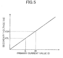
- required secondary voltage V2 of such an ignition device is generally low (V2L) while the engine speed is low relative to a predetermined value N2 and high (V2H) while the engine speed is high relative to the predetermined value N2, due to a correlation between the required secondary voltage V2 and compression pressure in the engine.
- V2L voltage
- V2H voltage
- the secondary voltage V2 increases to V2L and to V2H.
- the generator needs a large-capacity magneto coil capable of generating a sufficient amount of power from when the engine speed is low. This results in increase in the size of the generator, which is disadvantageous in terms of cost.
- An object of at least the preferred embodiments of the invention is to provide an ignition device for a battery-less engine capable of securely performing ignition of the battery-less engine from a state where the engine is started through a manual starting operation to a state where the engine in a high engine speed range, without particularly increasing the capacity of a magneto coil of a generator.
- an ignition device for a battery-less engine is configured such that a transistor-type ignition control circuit of an engine including a manual starting device is actuated by using output of a generator driven by the engine, and that a primary winding of an ignition coil is powered from the ignition control circuit.
- the ignition control circuit is configured such that a primary powering time period for powering the primary winding from the ignition control circuit is set shorter than a predetermined time period while an engine speed of the engine is within a low engine speed range below a predetermined engine speed and the primary powering time period is set equal to or longer than the predetermined time period while the engine speed of the engine is within a high engine speed range at and above the predetermined engine speed.
- the primary powering time period for powering the primary winding from the ignition control circuit is set shorter than the predetermined time period while the engine speed is within the low engine speed range below the predetermined engine speed.
- the primary powering time period is set equal to or longer than the predetermined time period while the engine speed is within the high engine speed range equal to or greater than the predetermined engine speed.
- the primary powering time period is relatively short, power consumption of the primary winding is small.
- the power outputted from the generator is sufficient to actuate the spark plug and start the engine.
- the ignition control circuit is actuated well and securely.
- the spark plug securely generates an electric spark, thereby making it possible to easily perform complete combustion in the engine and start the engine.
- the engine may enter the high engine speed range, in which case the primary powering time period is controlled to or above a predetermined time period.
- the secondary voltage is increased.
- the spark plug is securely actuated, thereby making it possible to achieve a good high rotation state. Accordingly, ignition of the battery-less engine can be performed securely from a state where the engine is started via a manual starting operation to a state where the engine is in the high engine speed range, without particularly increasing the capacity of a magneto coil of the generator.
- a method for starting and operating a battery-less engine said engine being provided with a transistor-type ignition control circuit that includes a manual starting device, said ignition control circuit being actuated using an output of a generator driven by the engine, and wherein a primary winding of an ignition coil is powered from the ignition control circuit, comprising the steps of: determining a speed of the engine; setting a primary powering time period for powering the primary winding from the ignition control circuit to a value that is less than a predetermined time period when the engine is operating in a low engine speed range, said low engine speed range being below a predetermined engine speed; and, setting the primary powering time period for powering the primary winding from the ignition control circuit to a value that is at least equal to the predetermined time period when the engine speed is operating in a high engine speed range, said high engine speed range being equal to or greater than said predetermined engine speed.
- reference numeral 1 denotes an engine for a work machine such as a pump, a string trimmer, a small cultivator, or the like, which is battery-less, i.e. equipped with no battery.
- the engine 1 includes a recoil starter 2 as a manual starting device.
- a crankshaft 1a of the engine 1 is directly connected to and drives a generator 3.
- the generator 3 includes a magneto coil 3a and a pulser coil 3b, and an electronic control unit 4 is connected to them.
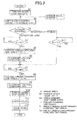
- the electronic control unit 4 includes a power supply circuit 5, a pulse processing circuit 6, and a transistor-type ignition control circuit 7.
- the power supply circuit 5 converts alternating-current output of the magneto coil 3a into direct-current output and adjusts it.
- the pulse processing circuit 6 is supplied with power from the power supply circuit 5 and adjusts each output pulse of the pulser coil 3b into a predetermined signal waveform.
- the ignition control circuit 7 powers a primary winding 8a of an ignition coil 8 by using the output of the power supply circuit 5.
- a spark plug 9 of the engine 1 is connected to a secondary winding 8b of the ignition coil 8.
- the ignition control circuit 7 determines an ignition timing, i.e. the timing to power the primary winding 8a, based upon the output signal of the pulse processing circuit 6. At the same time, the ignition control circuit 7 detects the engine speed of the engine 1 and controls and switches the time period of the powering of the primary winding to a value smaller than a predetermined value while the engine speed is within a predetermined low engine speed range including engine speeds for cranking, and to a value equal to or greater than the predetermined value while the engine speed is within a high engine speed range lying next to the low engine speed range.
- a short circuit 10 connected between the ignition control circuit 7 and the primary winding 8a is provided with a normally-open engine stop switch 11.
- the engine stop switch 11 when the engine stop switch 11 is turned on, the output side of the ignition control circuit 7 is brought into a short-circuited state, thereby disabling the powering of the primary winding 8a. Hence, the engine operation can be stopped.
- step S1 the engine stop switch 11 is turned off in step S1.
- the recoil starter 2 is operated to crank the engine 1.
- the rotations of the crankshaft 1a by the operation of the recoil starter are transmitted to and drive the generator 3 and thereby actuate the power supply circuit 5.
- step S2 the ignition control circuit 7 shifts to a standby state in response to input from the power supply circuit 5.
- step S3 the engine 1 is determined to be rotating. Such determination indicates that the engine 1 is battery-less.
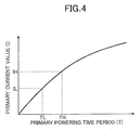
- step S4 If the engine 1 is determined as battery-less in step S3, it is determined in step S4 whether an engine speed N is equal to or greater than an ignition-start engine speed N1 (see FIG. 3 ). In the case of YES, the ignition control circuit 7 controls a primary powering time period T for the primary winding 8a to a relatively short predetermined time period TL (see FIG. 4 ) in step S5. As a result, in step S6, secondary voltage V2 generated in the secondary winding 8b becomes a relatively low value V2L (see FIG. 5 ).
- step S7 After the engine is started, it is determined in step S7 whether the engine speed N is equal to or greater than a relatively high predetermined value N2 (see FIG. 3 ). In the case of YES, in step S8, the primary powering time period T is controlled to a relatively long predetermined time period TH (see FIG. 4 ). As a result, in step S9, the secondary voltage V2 becomes a relatively high value V2H (see FIG. 5 ). Thus, in the high engine speed range, too, where the compression pressure in the engine is increased, the spark plug 9 is securely actuated, thereby making it possible to achieve a good high rotation state.
- ignition of the battery-less engine 1 can be performed securely not only when the engine 1 is started by operation of the recoil starter 2 but also when the engine 1 is operated in the high engine speed range, without particularly increasing the capacity of the magneto coil 3a of the generator 3.
- step S10 the engine stop switch 11 is turned on (step S10).
- step S11 the actuation of the spark plug 9 stops automatically (step S11), so that the engine 1 shifts to a stopped state (step S12).
- step S2 the secondary voltage V2 is V2H, which is relatively high as compared to the beginning of the start of the engine.
- the present invention is not limited to the foregoing embodiment, and various design changes can be made without departing from the scope of the gist of the present invention.
- a kick starter may be employed instead of the recoil starter 2.
- the primary powering time period is switched between two levels based on two, high and low engine speed ranges in the foregoing embodiment, there may be three or more different engine speed ranges, and the primary powering time period may be switched between three or more levels corresponding to those ranges.
Landscapes
- Engineering & Computer Science (AREA)
- Chemical & Material Sciences (AREA)
- Combustion & Propulsion (AREA)
- Mechanical Engineering (AREA)
- General Engineering & Computer Science (AREA)
- Ignition Installations For Internal Combustion Engines (AREA)
Applications Claiming Priority (1)
| Application Number | Priority Date | Filing Date | Title |
|---|---|---|---|
| JP2012186567A JP5910943B2 (ja) | 2012-08-27 | 2012-08-27 | バッテリレスエンジンの点火装置 |
Publications (2)
| Publication Number | Publication Date |
|---|---|
| EP2703637A1 EP2703637A1 (en) | 2014-03-05 |
| EP2703637B1 true EP2703637B1 (en) | 2016-10-26 |
Family
ID=48998417
Family Applications (1)
| Application Number | Title | Priority Date | Filing Date |
|---|---|---|---|
| EP13179661.7A Not-in-force EP2703637B1 (en) | 2012-08-27 | 2013-08-08 | Ignition device for battery-less engine and method for starting and operating battery-less engine |
Country Status (3)
| Country | Link |
|---|---|
| US (1) | US9366218B2 (enExample) |
| EP (1) | EP2703637B1 (enExample) |
| JP (1) | JP5910943B2 (enExample) |
Families Citing this family (3)
| Publication number | Priority date | Publication date | Assignee | Title |
|---|---|---|---|---|
| JP6815260B2 (ja) * | 2017-04-04 | 2021-01-20 | 本田技研工業株式会社 | エンジンシステム |
| JP7136631B2 (ja) * | 2018-08-29 | 2022-09-13 | ダイハツ工業株式会社 | 内燃機関の制御装置 |
| US11319915B2 (en) | 2020-06-11 | 2022-05-03 | Kohler Co. | Engine system, and method of starting the engine |
Family Cites Families (24)
| Publication number | Priority date | Publication date | Assignee | Title |
|---|---|---|---|---|
| US4043302A (en) * | 1975-08-25 | 1977-08-23 | Motorola, Inc. | Solid state ignition system and method for linearly regulating the dwell time thereof |
| JPS5823281A (ja) * | 1981-08-06 | 1983-02-10 | Nissan Motor Co Ltd | 内燃機関の点火装置 |
| DE3303675C2 (de) | 1982-02-03 | 1987-03-26 | Mitsubishi Denki K.K., Tokio/Tokyo | Brennkraftmaschinen-Zündsystem |
| JPS58133475A (ja) * | 1982-02-03 | 1983-08-09 | Mitsubishi Electric Corp | 内燃機関点火装置 |
| JPS5947366U (ja) * | 1982-09-21 | 1984-03-29 | 新電元工業株式会社 | トランジスタ点火装置 |
| DE3321768A1 (de) * | 1983-06-16 | 1984-12-20 | Robert Bosch Gmbh, 7000 Stuttgart | Zuendanlage fuer brennkraftmaschinen |
| JP2518904B2 (ja) | 1988-10-07 | 1996-07-31 | 株式会社テック | 給紙方法 |
| US5245252A (en) * | 1988-11-15 | 1993-09-14 | Frus John R | Apparatus and method for providing ignition to a turbine engine |
| JP2518904Y2 (ja) | 1991-06-14 | 1996-12-04 | 川崎重工業株式会社 | バッテリレス車両用始動装置 |
| US5383433A (en) * | 1993-05-19 | 1995-01-24 | Briggs & Stratton Corporation | Microprocessor-controlled inductive ignition system |
| DE4328524A1 (de) * | 1993-08-25 | 1995-03-02 | Volkswagen Ag | Steuerbare Zündanlage |
| BG100297A (en) * | 1996-01-22 | 1997-08-29 | БЪЧВАРОВ Христо | SYSTEM OF STARTING INTERNAL COMBUSTION ENGINES (ICEs) |
| JP3421211B2 (ja) * | 1997-02-03 | 2003-06-30 | 三菱電機株式会社 | 内燃機関の点火制御装置 |
| US6058908A (en) * | 1998-05-29 | 2000-05-09 | Autotronic Controls Corporation | Hall effect ignition |
| DE10201422B4 (de) * | 2001-09-03 | 2015-06-18 | Prüfrex-Elektro-Apparatebau Inh. Helga Müller, geb. Dutschke | Verfahren und Anordnung zur Steuerung und/oder Diagnose einer Brennkraftmaschine |
| US7017565B2 (en) * | 2004-03-17 | 2006-03-28 | Fuller Gerald D | Supplemental capacitive discharge ignition system |
| US6932064B1 (en) * | 2004-04-28 | 2005-08-23 | Walbro Engine Management, L.L.C. | Capacitor discharge ignition |
| WO2007038945A1 (en) * | 2005-09-21 | 2007-04-12 | Freescale Semiconductor, Inc. | Controller and method for controlling an ignition coil |
| DE102007031396B4 (de) * | 2007-07-05 | 2020-04-23 | Andreas Stihl Ag & Co. Kg | Verfahren zum Betrieb eines Zweitaktmotors |
| JP4925976B2 (ja) * | 2007-08-29 | 2012-05-09 | 株式会社ケーヒン | 内燃機関制御装置 |
| DE102009040321B4 (de) * | 2009-09-05 | 2020-08-27 | Andreas Stihl Ag & Co. Kg | Verfahren zum Betrieb eines Verbrennungsmotors |
| DE102009058971A1 (de) * | 2009-12-18 | 2011-06-22 | Andreas Stihl AG & Co. KG, 71336 | Verfahren und Vorrichtung zur Bereitstellung elektrischer Energie für ein Motorsteuergerät |
| US8286617B2 (en) * | 2010-12-23 | 2012-10-16 | Grady John K | Dual coil ignition |
| JP2012136965A (ja) * | 2010-12-24 | 2012-07-19 | Mitsubishi Motors Corp | 内燃機関の制御装置 |
-
2012
- 2012-08-27 JP JP2012186567A patent/JP5910943B2/ja not_active Expired - Fee Related
-
2013
- 2013-08-08 EP EP13179661.7A patent/EP2703637B1/en not_active Not-in-force
- 2013-08-15 US US13/967,592 patent/US9366218B2/en not_active Expired - Fee Related
Also Published As
| Publication number | Publication date |
|---|---|
| US20140053820A1 (en) | 2014-02-27 |
| EP2703637A1 (en) | 2014-03-05 |
| US9366218B2 (en) | 2016-06-14 |
| JP5910943B2 (ja) | 2016-04-27 |
| JP2014043811A (ja) | 2014-03-13 |
Similar Documents
| Publication | Publication Date | Title |
|---|---|---|
| EP2339168B1 (en) | Engine control apparatus and engine control method | |
| US6868832B2 (en) | Electronic controlled fuel injection apparatus of internal combustion engine | |
| US9982647B2 (en) | Engine start system | |
| JP6665734B2 (ja) | エンジン始動装置 | |
| EP2703637B1 (en) | Ignition device for battery-less engine and method for starting and operating battery-less engine | |
| JP2003506627A (ja) | 自動車用の始動及び充電装置 | |
| JP2017203435A (ja) | エンジンの始動制御システム | |
| EP1445481A4 (en) | MOTOR STATE CONTROL METHOD AND DEVICE | |
| WO2013035168A1 (ja) | 車両用始動装置 | |
| JP2018170862A (ja) | 発電機システム | |
| US6957636B2 (en) | Apparatus and method for preventing an overshoot in the rotation speed of an internal-combustion engine | |
| JP2014043811A5 (enExample) | ||
| US9777693B2 (en) | Method and device for controlling the operation of an internal combustion engine of a portable work device | |
| JP4618693B2 (ja) | エンジン発電システムおよびそのコントローラ | |
| JP2018084219A (ja) | 始動制御装置、始動装置及び始動制御システム | |
| US10655588B2 (en) | Restart control system | |
| JP2021017874A (ja) | エンジン始動システム及びエンジン始動方法 | |
| JP2009255128A (ja) | エンジン駆動溶接機 | |
| KR101791700B1 (ko) | 건설기계의 연비 절감 장치 및 방법 | |
| TWI541432B (zh) | 引擎啓動裝置 | |
| JP4480026B2 (ja) | エンジンの点火装置 | |
| KR20040011935A (ko) | 하이브리드 전기 차량의 모터 시동 제어방법 | |
| JP2017206050A (ja) | ハイブリッド車両 | |
| KR19990009146A (ko) | 차량의 엔진 시동방법 | |
| JPWO2013035168A1 (ja) | 車両用始動装置 |
Legal Events
| Date | Code | Title | Description |
|---|---|---|---|
| 17P | Request for examination filed |
Effective date: 20130808 |
|
| AK | Designated contracting states |
Kind code of ref document: A1 Designated state(s): AL AT BE BG CH CY CZ DE DK EE ES FI FR GB GR HR HU IE IS IT LI LT LU LV MC MK MT NL NO PL PT RO RS SE SI SK SM TR |
|
| AX | Request for extension of the european patent |
Extension state: BA ME |
|
| PUAI | Public reference made under article 153(3) epc to a published international application that has entered the european phase |
Free format text: ORIGINAL CODE: 0009012 |
|
| RIC1 | Information provided on ipc code assigned before grant |
Ipc: F02P 1/08 20060101AFI20150716BHEP Ipc: F02P 17/12 20060101ALN20150716BHEP Ipc: F02N 3/02 20060101ALN20150716BHEP Ipc: F02P 15/12 20060101ALN20150716BHEP Ipc: F02N 11/08 20060101ALN20150716BHEP |
|
| GRAP | Despatch of communication of intention to grant a patent |
Free format text: ORIGINAL CODE: EPIDOSNIGR1 |
|
| INTG | Intention to grant announced |
Effective date: 20151109 |
|
| GRAS | Grant fee paid |
Free format text: ORIGINAL CODE: EPIDOSNIGR3 |
|
| RIC1 | Information provided on ipc code assigned before grant |
Ipc: F02P 15/12 20060101ALN20160323BHEP Ipc: F02N 3/02 20060101ALN20160323BHEP Ipc: F02P 17/12 20060101ALN20160323BHEP Ipc: F02P 1/08 20060101AFI20160323BHEP Ipc: F02N 11/08 20060101ALN20160323BHEP |
|
| GRAP | Despatch of communication of intention to grant a patent |
Free format text: ORIGINAL CODE: EPIDOSNIGR1 |
|
| INTG | Intention to grant announced |
Effective date: 20160531 |
|
| GRAS | Grant fee paid |
Free format text: ORIGINAL CODE: EPIDOSNIGR3 |
|
| GRAA | (expected) grant |
Free format text: ORIGINAL CODE: 0009210 |
|
| AK | Designated contracting states |
Kind code of ref document: B1 Designated state(s): AL AT BE BG CH CY CZ DE DK EE ES FI FR GB GR HR HU IE IS IT LI LT LU LV MC MK MT NL NO PL PT RO RS SE SI SK SM TR |
|
| REG | Reference to a national code |
Ref country code: GB Ref legal event code: FG4D |
|
| REG | Reference to a national code |
Ref country code: CH Ref legal event code: EP |
|
| REG | Reference to a national code |
Ref country code: AT Ref legal event code: REF Ref document number: 840213 Country of ref document: AT Kind code of ref document: T Effective date: 20161115 |
|
| REG | Reference to a national code |
Ref country code: IE Ref legal event code: FG4D |
|
| REG | Reference to a national code |
Ref country code: DE Ref legal event code: R096 Ref document number: 602013013150 Country of ref document: DE |
|
| REG | Reference to a national code |
Ref country code: LT Ref legal event code: MG4D |
|
| PG25 | Lapsed in a contracting state [announced via postgrant information from national office to epo] |
Ref country code: LV Free format text: LAPSE BECAUSE OF FAILURE TO SUBMIT A TRANSLATION OF THE DESCRIPTION OR TO PAY THE FEE WITHIN THE PRESCRIBED TIME-LIMIT Effective date: 20161026 |
|
| REG | Reference to a national code |
Ref country code: NL Ref legal event code: MP Effective date: 20161026 |
|
| REG | Reference to a national code |
Ref country code: AT Ref legal event code: MK05 Ref document number: 840213 Country of ref document: AT Kind code of ref document: T Effective date: 20161026 |
|
| RIN2 | Information on inventor provided after grant (corrected) |
Inventor name: KEIICHIRO, BUNGO Inventor name: TAKESHIGE, TAKAMASA |
|
| PG25 | Lapsed in a contracting state [announced via postgrant information from national office to epo] |
Ref country code: NO Free format text: LAPSE BECAUSE OF FAILURE TO SUBMIT A TRANSLATION OF THE DESCRIPTION OR TO PAY THE FEE WITHIN THE PRESCRIBED TIME-LIMIT Effective date: 20170126 Ref country code: SE Free format text: LAPSE BECAUSE OF FAILURE TO SUBMIT A TRANSLATION OF THE DESCRIPTION OR TO PAY THE FEE WITHIN THE PRESCRIBED TIME-LIMIT Effective date: 20161026 Ref country code: LT Free format text: LAPSE BECAUSE OF FAILURE TO SUBMIT A TRANSLATION OF THE DESCRIPTION OR TO PAY THE FEE WITHIN THE PRESCRIBED TIME-LIMIT Effective date: 20161026 Ref country code: GR Free format text: LAPSE BECAUSE OF FAILURE TO SUBMIT A TRANSLATION OF THE DESCRIPTION OR TO PAY THE FEE WITHIN THE PRESCRIBED TIME-LIMIT Effective date: 20170127 |
|
| PG25 | Lapsed in a contracting state [announced via postgrant information from national office to epo] |
Ref country code: IS Free format text: LAPSE BECAUSE OF FAILURE TO SUBMIT A TRANSLATION OF THE DESCRIPTION OR TO PAY THE FEE WITHIN THE PRESCRIBED TIME-LIMIT Effective date: 20170226 Ref country code: HR Free format text: LAPSE BECAUSE OF FAILURE TO SUBMIT A TRANSLATION OF THE DESCRIPTION OR TO PAY THE FEE WITHIN THE PRESCRIBED TIME-LIMIT Effective date: 20161026 Ref country code: ES Free format text: LAPSE BECAUSE OF FAILURE TO SUBMIT A TRANSLATION OF THE DESCRIPTION OR TO PAY THE FEE WITHIN THE PRESCRIBED TIME-LIMIT Effective date: 20161026 Ref country code: NL Free format text: LAPSE BECAUSE OF FAILURE TO SUBMIT A TRANSLATION OF THE DESCRIPTION OR TO PAY THE FEE WITHIN THE PRESCRIBED TIME-LIMIT Effective date: 20161026 Ref country code: BE Free format text: LAPSE BECAUSE OF FAILURE TO SUBMIT A TRANSLATION OF THE DESCRIPTION OR TO PAY THE FEE WITHIN THE PRESCRIBED TIME-LIMIT Effective date: 20161026 Ref country code: PT Free format text: LAPSE BECAUSE OF FAILURE TO SUBMIT A TRANSLATION OF THE DESCRIPTION OR TO PAY THE FEE WITHIN THE PRESCRIBED TIME-LIMIT Effective date: 20170227 Ref country code: RS Free format text: LAPSE BECAUSE OF FAILURE TO SUBMIT A TRANSLATION OF THE DESCRIPTION OR TO PAY THE FEE WITHIN THE PRESCRIBED TIME-LIMIT Effective date: 20161026 Ref country code: FI Free format text: LAPSE BECAUSE OF FAILURE TO SUBMIT A TRANSLATION OF THE DESCRIPTION OR TO PAY THE FEE WITHIN THE PRESCRIBED TIME-LIMIT Effective date: 20161026 Ref country code: PL Free format text: LAPSE BECAUSE OF FAILURE TO SUBMIT A TRANSLATION OF THE DESCRIPTION OR TO PAY THE FEE WITHIN THE PRESCRIBED TIME-LIMIT Effective date: 20161026 Ref country code: AT Free format text: LAPSE BECAUSE OF FAILURE TO SUBMIT A TRANSLATION OF THE DESCRIPTION OR TO PAY THE FEE WITHIN THE PRESCRIBED TIME-LIMIT Effective date: 20161026 |
|
| RIN2 | Information on inventor provided after grant (corrected) |
Inventor name: BUNGO, KEIICHIRO Inventor name: TAKESHIGE, TAKAMASA |
|
| REG | Reference to a national code |
Ref country code: DE Ref legal event code: R097 Ref document number: 602013013150 Country of ref document: DE |
|
| PG25 | Lapsed in a contracting state [announced via postgrant information from national office to epo] |
Ref country code: SK Free format text: LAPSE BECAUSE OF FAILURE TO SUBMIT A TRANSLATION OF THE DESCRIPTION OR TO PAY THE FEE WITHIN THE PRESCRIBED TIME-LIMIT Effective date: 20161026 Ref country code: CZ Free format text: LAPSE BECAUSE OF FAILURE TO SUBMIT A TRANSLATION OF THE DESCRIPTION OR TO PAY THE FEE WITHIN THE PRESCRIBED TIME-LIMIT Effective date: 20161026 Ref country code: EE Free format text: LAPSE BECAUSE OF FAILURE TO SUBMIT A TRANSLATION OF THE DESCRIPTION OR TO PAY THE FEE WITHIN THE PRESCRIBED TIME-LIMIT Effective date: 20161026 Ref country code: RO Free format text: LAPSE BECAUSE OF FAILURE TO SUBMIT A TRANSLATION OF THE DESCRIPTION OR TO PAY THE FEE WITHIN THE PRESCRIBED TIME-LIMIT Effective date: 20161026 Ref country code: DK Free format text: LAPSE BECAUSE OF FAILURE TO SUBMIT A TRANSLATION OF THE DESCRIPTION OR TO PAY THE FEE WITHIN THE PRESCRIBED TIME-LIMIT Effective date: 20161026 |
|
| REG | Reference to a national code |
Ref country code: FR Ref legal event code: PLFP Year of fee payment: 5 |
|
| PG25 | Lapsed in a contracting state [announced via postgrant information from national office to epo] |
Ref country code: SM Free format text: LAPSE BECAUSE OF FAILURE TO SUBMIT A TRANSLATION OF THE DESCRIPTION OR TO PAY THE FEE WITHIN THE PRESCRIBED TIME-LIMIT Effective date: 20161026 Ref country code: BG Free format text: LAPSE BECAUSE OF FAILURE TO SUBMIT A TRANSLATION OF THE DESCRIPTION OR TO PAY THE FEE WITHIN THE PRESCRIBED TIME-LIMIT Effective date: 20170126 Ref country code: IT Free format text: LAPSE BECAUSE OF FAILURE TO SUBMIT A TRANSLATION OF THE DESCRIPTION OR TO PAY THE FEE WITHIN THE PRESCRIBED TIME-LIMIT Effective date: 20161026 |
|
| PLBE | No opposition filed within time limit |
Free format text: ORIGINAL CODE: 0009261 |
|
| STAA | Information on the status of an ep patent application or granted ep patent |
Free format text: STATUS: NO OPPOSITION FILED WITHIN TIME LIMIT |
|
| 26N | No opposition filed |
Effective date: 20170727 |
|
| PG25 | Lapsed in a contracting state [announced via postgrant information from national office to epo] |
Ref country code: SI Free format text: LAPSE BECAUSE OF FAILURE TO SUBMIT A TRANSLATION OF THE DESCRIPTION OR TO PAY THE FEE WITHIN THE PRESCRIBED TIME-LIMIT Effective date: 20161026 |
|
| REG | Reference to a national code |
Ref country code: CH Ref legal event code: PL |
|
| PG25 | Lapsed in a contracting state [announced via postgrant information from national office to epo] |
Ref country code: MC Free format text: LAPSE BECAUSE OF FAILURE TO SUBMIT A TRANSLATION OF THE DESCRIPTION OR TO PAY THE FEE WITHIN THE PRESCRIBED TIME-LIMIT Effective date: 20161026 |
|
| PG25 | Lapsed in a contracting state [announced via postgrant information from national office to epo] |
Ref country code: LI Free format text: LAPSE BECAUSE OF NON-PAYMENT OF DUE FEES Effective date: 20170831 Ref country code: CH Free format text: LAPSE BECAUSE OF NON-PAYMENT OF DUE FEES Effective date: 20170831 |
|
| REG | Reference to a national code |
Ref country code: IE Ref legal event code: MM4A |
|
| PG25 | Lapsed in a contracting state [announced via postgrant information from national office to epo] |
Ref country code: LU Free format text: LAPSE BECAUSE OF NON-PAYMENT OF DUE FEES Effective date: 20170808 |
|
| REG | Reference to a national code |
Ref country code: FR Ref legal event code: PLFP Year of fee payment: 6 |
|
| PG25 | Lapsed in a contracting state [announced via postgrant information from national office to epo] |
Ref country code: IE Free format text: LAPSE BECAUSE OF NON-PAYMENT OF DUE FEES Effective date: 20170808 |
|
| PG25 | Lapsed in a contracting state [announced via postgrant information from national office to epo] |
Ref country code: MT Free format text: LAPSE BECAUSE OF NON-PAYMENT OF DUE FEES Effective date: 20170808 |
|
| PG25 | Lapsed in a contracting state [announced via postgrant information from national office to epo] |
Ref country code: HU Free format text: LAPSE BECAUSE OF FAILURE TO SUBMIT A TRANSLATION OF THE DESCRIPTION OR TO PAY THE FEE WITHIN THE PRESCRIBED TIME-LIMIT; INVALID AB INITIO Effective date: 20130808 |
|
| PG25 | Lapsed in a contracting state [announced via postgrant information from national office to epo] |
Ref country code: CY Free format text: LAPSE BECAUSE OF NON-PAYMENT OF DUE FEES Effective date: 20161026 |
|
| PG25 | Lapsed in a contracting state [announced via postgrant information from national office to epo] |
Ref country code: MK Free format text: LAPSE BECAUSE OF FAILURE TO SUBMIT A TRANSLATION OF THE DESCRIPTION OR TO PAY THE FEE WITHIN THE PRESCRIBED TIME-LIMIT Effective date: 20161026 |
|
| REG | Reference to a national code |
Ref country code: DE Ref legal event code: R084 Ref document number: 602013013150 Country of ref document: DE |
|
| REG | Reference to a national code |
Ref country code: GB Ref legal event code: 746 Effective date: 20191219 |
|
| PG25 | Lapsed in a contracting state [announced via postgrant information from national office to epo] |
Ref country code: TR Free format text: LAPSE BECAUSE OF FAILURE TO SUBMIT A TRANSLATION OF THE DESCRIPTION OR TO PAY THE FEE WITHIN THE PRESCRIBED TIME-LIMIT Effective date: 20161026 |
|
| PG25 | Lapsed in a contracting state [announced via postgrant information from national office to epo] |
Ref country code: AL Free format text: LAPSE BECAUSE OF FAILURE TO SUBMIT A TRANSLATION OF THE DESCRIPTION OR TO PAY THE FEE WITHIN THE PRESCRIBED TIME-LIMIT Effective date: 20161026 |
|
| REG | Reference to a national code |
Ref country code: DE Ref legal event code: R082 Ref document number: 602013013150 Country of ref document: DE |
|
| PGFP | Annual fee paid to national office [announced via postgrant information from national office to epo] |
Ref country code: FR Payment date: 20210714 Year of fee payment: 9 |
|
| PGFP | Annual fee paid to national office [announced via postgrant information from national office to epo] |
Ref country code: GB Payment date: 20210701 Year of fee payment: 9 |
|
| PGFP | Annual fee paid to national office [announced via postgrant information from national office to epo] |
Ref country code: DE Payment date: 20220608 Year of fee payment: 10 |
|
| GBPC | Gb: european patent ceased through non-payment of renewal fee |
Effective date: 20220808 |
|
| PG25 | Lapsed in a contracting state [announced via postgrant information from national office to epo] |
Ref country code: FR Free format text: LAPSE BECAUSE OF NON-PAYMENT OF DUE FEES Effective date: 20220831 |
|
| PG25 | Lapsed in a contracting state [announced via postgrant information from national office to epo] |
Ref country code: GB Free format text: LAPSE BECAUSE OF NON-PAYMENT OF DUE FEES Effective date: 20220808 |
|
| REG | Reference to a national code |
Ref country code: DE Ref legal event code: R119 Ref document number: 602013013150 Country of ref document: DE |
|
| PG25 | Lapsed in a contracting state [announced via postgrant information from national office to epo] |
Ref country code: DE Free format text: LAPSE BECAUSE OF NON-PAYMENT OF DUE FEES Effective date: 20240301 |