EP2703229B1 - Anordnung zur Stromversorgung von in einem Kraftfahrzeug angeordneten elektrischen Verbrauchern - Google Patents
Anordnung zur Stromversorgung von in einem Kraftfahrzeug angeordneten elektrischen Verbrauchern Download PDFInfo
- Publication number
- EP2703229B1 EP2703229B1 EP12306023.8A EP12306023A EP2703229B1 EP 2703229 B1 EP2703229 B1 EP 2703229B1 EP 12306023 A EP12306023 A EP 12306023A EP 2703229 B1 EP2703229 B1 EP 2703229B1
- Authority
- EP
- European Patent Office
- Prior art keywords
- support elements
- vehicle
- motor car
- consumers
- electrical
- Prior art date
- Legal status (The legal status is an assumption and is not a legal conclusion. Google has not performed a legal analysis and makes no representation as to the accuracy of the status listed.)
- Revoked
Links
- 230000005611 electricity Effects 0.000 title 2
- 239000004020 conductor Substances 0.000 claims description 14
- 229910000838 Al alloy Inorganic materials 0.000 claims description 3
- XAGFODPZIPBFFR-UHFFFAOYSA-N aluminium Chemical compound [Al] XAGFODPZIPBFFR-UHFFFAOYSA-N 0.000 claims description 3
- 229910052782 aluminium Inorganic materials 0.000 claims description 3
- RYGMFSIKBFXOCR-UHFFFAOYSA-N Copper Chemical compound [Cu] RYGMFSIKBFXOCR-UHFFFAOYSA-N 0.000 claims description 2
- 229910000881 Cu alloy Inorganic materials 0.000 claims description 2
- 229910000831 Steel Inorganic materials 0.000 claims description 2
- 239000010949 copper Substances 0.000 claims description 2
- 229910052802 copper Inorganic materials 0.000 claims description 2
- 239000010959 steel Substances 0.000 claims description 2
- 239000004411 aluminium Substances 0.000 claims 1
- 230000000295 complement effect Effects 0.000 description 3
- -1 polyethylene Polymers 0.000 description 2
- FYYHWMGAXLPEAU-UHFFFAOYSA-N Magnesium Chemical compound [Mg] FYYHWMGAXLPEAU-UHFFFAOYSA-N 0.000 description 1
- 239000004952 Polyamide Substances 0.000 description 1
- 239000004698 Polyethylene Substances 0.000 description 1
- 239000004743 Polypropylene Substances 0.000 description 1
- 238000005275 alloying Methods 0.000 description 1
- 230000005540 biological transmission Effects 0.000 description 1
- 239000000919 ceramic Substances 0.000 description 1
- 230000009977 dual effect Effects 0.000 description 1
- 238000009434 installation Methods 0.000 description 1
- 239000011810 insulating material Substances 0.000 description 1
- 238000009413 insulation Methods 0.000 description 1
- 229910052749 magnesium Inorganic materials 0.000 description 1
- 239000011777 magnesium Substances 0.000 description 1
- 238000004519 manufacturing process Methods 0.000 description 1
- 229920002647 polyamide Polymers 0.000 description 1
- 229920000573 polyethylene Polymers 0.000 description 1
- 229920001155 polypropylene Polymers 0.000 description 1
- 229920002635 polyurethane Polymers 0.000 description 1
- 239000004814 polyurethane Substances 0.000 description 1
Images
Classifications
-
- B—PERFORMING OPERATIONS; TRANSPORTING
- B60—VEHICLES IN GENERAL
- B60L—PROPULSION OF ELECTRICALLY-PROPELLED VEHICLES; SUPPLYING ELECTRIC POWER FOR AUXILIARY EQUIPMENT OF ELECTRICALLY-PROPELLED VEHICLES; ELECTRODYNAMIC BRAKE SYSTEMS FOR VEHICLES IN GENERAL; MAGNETIC SUSPENSION OR LEVITATION FOR VEHICLES; MONITORING OPERATING VARIABLES OF ELECTRICALLY-PROPELLED VEHICLES; ELECTRIC SAFETY DEVICES FOR ELECTRICALLY-PROPELLED VEHICLES
- B60L50/00—Electric propulsion with power supplied within the vehicle
- B60L50/50—Electric propulsion with power supplied within the vehicle using propulsion power supplied by batteries or fuel cells
-
- B—PERFORMING OPERATIONS; TRANSPORTING
- B60—VEHICLES IN GENERAL
- B60L—PROPULSION OF ELECTRICALLY-PROPELLED VEHICLES; SUPPLYING ELECTRIC POWER FOR AUXILIARY EQUIPMENT OF ELECTRICALLY-PROPELLED VEHICLES; ELECTRODYNAMIC BRAKE SYSTEMS FOR VEHICLES IN GENERAL; MAGNETIC SUSPENSION OR LEVITATION FOR VEHICLES; MONITORING OPERATING VARIABLES OF ELECTRICALLY-PROPELLED VEHICLES; ELECTRIC SAFETY DEVICES FOR ELECTRICALLY-PROPELLED VEHICLES
- B60L1/00—Supplying electric power to auxiliary equipment of vehicles
- B60L1/02—Supplying electric power to auxiliary equipment of vehicles to electric heating circuits
- B60L1/04—Supplying electric power to auxiliary equipment of vehicles to electric heating circuits fed by the power supply line
- B60L1/06—Supplying electric power to auxiliary equipment of vehicles to electric heating circuits fed by the power supply line using only one supply
-
- B—PERFORMING OPERATIONS; TRANSPORTING
- B60—VEHICLES IN GENERAL
- B60L—PROPULSION OF ELECTRICALLY-PROPELLED VEHICLES; SUPPLYING ELECTRIC POWER FOR AUXILIARY EQUIPMENT OF ELECTRICALLY-PROPELLED VEHICLES; ELECTRODYNAMIC BRAKE SYSTEMS FOR VEHICLES IN GENERAL; MAGNETIC SUSPENSION OR LEVITATION FOR VEHICLES; MONITORING OPERATING VARIABLES OF ELECTRICALLY-PROPELLED VEHICLES; ELECTRIC SAFETY DEVICES FOR ELECTRICALLY-PROPELLED VEHICLES
- B60L50/00—Electric propulsion with power supplied within the vehicle
- B60L50/50—Electric propulsion with power supplied within the vehicle using propulsion power supplied by batteries or fuel cells
- B60L50/60—Electric propulsion with power supplied within the vehicle using propulsion power supplied by batteries or fuel cells using power supplied by batteries
- B60L50/66—Arrangements of batteries
-
- Y—GENERAL TAGGING OF NEW TECHNOLOGICAL DEVELOPMENTS; GENERAL TAGGING OF CROSS-SECTIONAL TECHNOLOGIES SPANNING OVER SEVERAL SECTIONS OF THE IPC; TECHNICAL SUBJECTS COVERED BY FORMER USPC CROSS-REFERENCE ART COLLECTIONS [XRACs] AND DIGESTS
- Y02—TECHNOLOGIES OR APPLICATIONS FOR MITIGATION OR ADAPTATION AGAINST CLIMATE CHANGE
- Y02T—CLIMATE CHANGE MITIGATION TECHNOLOGIES RELATED TO TRANSPORTATION
- Y02T10/00—Road transport of goods or passengers
- Y02T10/60—Other road transportation technologies with climate change mitigation effect
- Y02T10/70—Energy storage systems for electromobility, e.g. batteries
Definitions
- the invention relates to a motor vehicle with an arrangement for the power supply of electrical consumers arranged in the same according to the preamble of patent claim 1.
- Such a mounted in a motor vehicle assembly is for example from the JP 2006 290 227 A out.
- the arrangement is international state of the art and basically in all vehicles - hereinafter referred to as "vehicle” - available.
- vehicle As a voltage source, at least one battery is mounted in the vehicle, which may also be rechargeable, especially in electric vehicles.
- the word “battery” is used instead of the word “voltage source”.
- the vehicle-mounted electrical lines in so-called cable harnesses or cable harnesses are each combined to form a unit.
- Known wire harnesses go, for example, from the publications DE 37 10 642 A1 .
- the electrical consumers of a vehicle are connected via the electrical lines to the battery thereof.
- the electrical conductors of a cable harness have different lengths and usually also different cross sections. Because of the usually large number of individual, to be joined to a unit ladder is not only the production of a wiring harness consuming, but also its installation in the vehicle when, for example, consumers located in the rear should be connected to the battery.
- JP 2006 290 227 A describes an arrangement which is arranged as a relatively short unit in the region of the fittings of a vehicle and protrudes into the gap between the driver's seat and the passenger seat.
- a component On two connected to a voltage source and attached to the bottom of the vehicle, electrically conductive guides a component is slidably disposed. It serves, for example, the connection to a CD device or a DVD device arranged in the dashboard area.
- the component can be locked by means of a lever in a predetermined position.
- the invention has for its object to make the initially described vehicle so that the arranged in a vehicle consumers can be connected in a simpler manner with the battery.
- two support members are used, the same serve as a mechanically stable support for the structures of the vehicle and on the other hand as a kind of busbars for electrically conductive connection of the consumer to the battery thereof.
- the support members have contact points along their entire length, to which individual conductors leading to the consumers or even two or more previously combined conductors can be connected with a relatively short length, which is essentially only the distance of the consumer from one of the contact points or two Complementary contact points of the support elements is determined.
- the position of the battery inside the vehicle is not important. Since the support elements extend over the entire length of the vehicle, resulting in particular in the rear of the same essential simplifications, because even the local consumers can be connected via relatively short lines to the contact points of the support elements. This advantage is particularly important when the battery of the vehicle is mounted in the engine compartment of the same, so far away from the rear area.
- the support elements used in the arrangement according to the invention have a dual function. On the one hand, they are mechanically stable supports for the superstructures of the vehicle and, on the other hand, electrical conductors in the form of "busbars" for the electrically conductive connection of the consumers.
- the support elements must therefore be mechanically strong enough on the one hand and have on the other hand a sufficient electrical conductivity and a sufficiently large cross-section for the transmission of sufficient for all connectable consumers current. It is possible to design the support elements as a "busbars" for high current and connect the consumers according to their voltage requirements, if necessary via converter to the same.
- the support elements may for example consist of aluminum or an aluminum alloy, copper or a copper alloy or steel. For reasons of weight, it is advantageously possible to use aluminum or an aluminum alloy, in particular magnesium as alloying element, for the supporting elements.
- the support elements are surrounded all around and over their entire length by an insulation, by which they are covered against contact with the bodies of the vehicle.
- Suitable insulating materials include polyethylene, polyurethane, polyamide, polypropylene and ceramics.
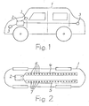
- FIG. 1 schematically illustrated vehicle 1 should be a car. It has in the illustrated embodiment arranged in the engine compartment battery 2 and a plurality of electrical loads 3, of which only three located at different positions in the vehicle 1 are shown as circles. All consumers 3 are electrically connected to the battery 2 via insulated conductors.
- the vehicle 1 may also have a different shape than a car and may also have less than four wheels. It can also be, for example, a van or a bus.
- Fig. 2 only the bottom area of the vehicle 1 is shown schematically. Any structures are omitted for clarity.
- two support elements 4 and 5 are mounted in the illustrated embodiment, the extend substantially over the entire length of the vehicle 1.
- more than two support elements can be arranged in the vehicle 1, which are optionally electrically connected to each other in a suitable manner.
- Each support element 4 or 5 is connected at one end to one of the poles of the battery 2.
- the battery 2 is arranged in the illustrated embodiment in the region of one end of the vehicle 1.
- the support elements 4 and 5 may be formed in one piece according to the drawings.
- the support members 4 and 5 may also each consist of two parts, which extend on different sides of the battery 2 each to an end portion of the vehicle 1.
- the support members 4 and 5 are made according to the foregoing embodiments of mechanically stable and electrically conductive material.
- the support elements 4 and 5 are fitted over their entire length with separate contact points 6 and 7, to which the leading to the consumers 3 electrical conductors can be connected directly or indirectly.
- the contact points 6 and 7 can be designed as customary in electrical connection technology contact points. It may accordingly be, for example, components for a plug connection, a screw connection or a welded or soldered connection. At the ends of the conductors to be connected in each case components are mounted, which can be connected in a simple manner with the attached to the contact points 6 and 7 of the support members 4 and 5 components.
- the conductors leading to the consumers 3 can be directly connected individually to two complementary contact points 6 and 7 of the support elements 4 and 5 having different polarities. It is also possible to combine two or more conductors and to connect together directly to two complementary contact points 6 and 7. This is particularly suitable for the connection of located in the rear area or in the engine compartment of the vehicle 1 larger number of consumers 3.
- An indirect connection of the conductors to the contact posts 6 and 7 is given when, for example, converters or other electrical or electronic devices must be interposed, which in turn are directly connected to the corresponding contact points 6 and 7.
- the conductors are then connected to such devices.
- the arrangement can be designed in this sense for multi-voltage systems, such as 12 V, 24 V or 48 V but also 600 V. In this case, the different voltages can be tapped at corresponding connections with the battery 2 on different support elements (busbars).
Landscapes
- Engineering & Computer Science (AREA)
- Power Engineering (AREA)
- Transportation (AREA)
- Mechanical Engineering (AREA)
- Life Sciences & Earth Sciences (AREA)
- Sustainable Development (AREA)
- Sustainable Energy (AREA)
- Battery Mounting, Suspending (AREA)
- Charge And Discharge Circuits For Batteries Or The Like (AREA)
- Body Structure For Vehicles (AREA)
- Electric Propulsion And Braking For Vehicles (AREA)
Description
- Die Erfindung bezieht sich auf ein Kraftfahrzeug mit einer Anordnung zur Stromversorgung von in demselben angeordneten elektrischen Verbrauchern gemäß dem Oberbegriff des Patentanspruchs 1.
- Eine solche in einem Kraftfahrzeug angebrachte Anordnung geht beispielsweise aus der
JP 2006 290 227 A - Die Anordnung ist internationaler Stand der Technik und grundsätzlich in allen Kraftfahrzeugen - im folgenden kurz "Fahrzeug" genannt - vorhanden. Als Spannungsquelle ist mindestens eine Batterie im Fahrzeug angebracht, die insbesondere bei Elektrofahrzeugen auch wiederaufladbar sein kann. Im folgenden wird statt des Wortes "Spannungsquelle" das Wort "Batterie" verwendet.
- In bekannter Technik sind die in einem Fahrzeug montierten elektrischen Leitungen in sogenannten Kabelbäumen bzw. Kabelsträngen jeweils zu einer Einheit zusammengefaßt. Bekannte Kabelbäume gehen beispielsweise aus den Druckschriften
DE 37 10 642 A1 ,DE 36 09 704 A1 undDE 36 16 649 A1 hervor. Die elektrischen Verbraucher eines Fahrzeugs sind über die elektrischen Leitungen mit der Batterie desselben verbunden. - Die elektrischen Leiter eines Kabelbaums haben unterschiedliche Längen und in der Regel auch unterschiedliche Querschnitte. Wegen der meist großen Anzahl einzelner, zu einer Einheit zu verbindenden Leiter ist nicht nur die Herstellung eines Kabelbaums aufwendig, sondern auch seine Verlegung im Fahrzeug, wenn beispielsweise im Heckbereich befindliche Verbraucher mit der Batterie verbunden werden sollen.
- Die eingangs erwähnte
JP 2006 290 227 A - Der Erfindung liegt die Aufgabe zugrunde, das eingangs geschilderte Fahrzeug so zu gestalten, daß die in einem Fahrzeug angeordneten Verbraucher auf einfachere Art und Weise mit der Batterie verbunden werden können.
- Diese Aufgabe wird entsprechend den kennzeichnenden Merkmalen des Patentanspruchs 1 gelöst.
- Bei dem Fahrzeug mit dieser Anordnung sind zwei Tragelemente eingesetzt, die einerseits als mechanisch stabile Träger für die Aufbauten des Fahrzeugs und andererseits als eine Art Stromschienen zum elektrisch leitenden Anschluß der Verbraucher an die Batterie desselben dienen. Die Tragelemente haben auf ihrer ganzen Länge Kontaktstellen, an welche zu den Verbrauchern führende einzelne Leiter oder auch zwei oder mehr vorher zusammengefaßte Leiter mit einer relativ kurzen Länge angeschlossen werden können, die im wesentlichen nur vom Abstand der Verbraucher von einer der Kontaktstellen bzw. von zwei komplementären Kontaktstellen der Tragelemente bestimmt ist. Die Position der Batterie innerhalb des Fahrzeugs ist dabei nicht von Bedeutung. Da die Tragelemente sich über die ganze Länge des Fahrzeugs erstrecken, ergeben sich insbesondere im Heckbereich desselben wesentliche Vereinfachungen, weil auch die dortigen Verbraucher über relativ kurze Leitungen an die Kontaktstellen der Tragelemente angeschlossen werden können. Dieser Vorteil ist insbesondere dann von Bedeutung, wenn die Batterie des Fahrzeugs im Motorraum desselben angebracht ist, also weit entfernt vom Heckbereich.
- Ein Ausführungsbeispiel des Erfindungsgegenstandes ist in den Zeichnungen dargestellt.
- Es zeigen:
-
Fig. 1 in schematischer Darstellung eine Seitenansicht eines Fahrzeugs. -
Fig. 2 ebenfalls in schematischer Darstellung eine Anordnung nach der Erfindung. - Die in der Anordnung nach der Erfindung verwendeten Tragelemente haben eine Doppelfunktion. Sie sind einerseits mechanisch stabiler Träger für die Aufbauten des Fahrzeugs und andererseits elektrischer Leiter in Form von "Stromschienen" zum elektrisch leitenden Anschluß der Verbraucher. Die Tragelemente müssen auf der einen Seite also mechanisch ausreichend fest sein und auf der anderen Seite eine ausreichende elektrische Leitfähigkeit und einen ausreichend großen Querschnitt zur Übertragung eines für alle anschließbaren Verbraucher ausreichenden Stroms haben. Dabei ist es möglich, die Tragelemente als "Stromschienen" für Hochstrom auszulegen und die Verbraucher entsprechend ihrem Spannungsbedarf gegebenenfalls über Wandler an dieselben anzuschließen. In diesem Sinne können die Tragelemente beispielsweise aus Aluminium bzw. einer Aluminiumlegierung, aus Kupfer bzw. einer Kupferlegierung oder aus Stahl bestehen. Aus Gewichtsgründen kann mit Vorteil Aluminium bzw. eine Aluminiumlegierung, insbesondere mit Magnesium als Legierungselement, für die Tragelemente eingesetzt werden.
- Die Tragelemente sind rundum und über ihre ganze Länge von einer Isolierung umgeben, durch welche sie gegenüber den Aufbauten des Fahrzeugs berührungssicher abgedeckt sind. Geeignete Isoliermaterialien sind beispielsweise Polyethylen, Polyurethan, Polyamid, Polypropylen und Keramik.
- Das in
Fig. 1 schematisch dargestellte Fahrzeug 1 soll ein PKW sein. Es hat im dargestellten Ausführungsbeispiel eine im Motorraum angeordnete Batterie 2 und eine Vielzahl von elektrischen Verbrauchern 3, von denen nur drei an unterschiedlichen Positionen im Fahrzeug 1 befindliche als Kreise eingezeichnet sind. Alle Verbraucher 3 sind über isolierte Leiter elektrisch leitend mit der Batterie 2 verbunden. Das Fahrzeug 1 kann auch eine andere Form als ein PKW haben und es kann auch weniger als vier Räder aufweisen. Es kann beispielsweise auch ein Transporter oder ein Bus sein. - In
Fig. 2 ist nur der Bodenbereich des Fahrzeugs 1 schematisch dargestellt. Jedwede Aufbauten sind der Übersichtlichkeit halber fortgelassen. In diesem Bodenbereich sind im dargestellten Ausführungsbeispiel zwei Tragelemente 4 und 5 angebracht, die sich im wesentlichen über die ganze Länge des Fahrzeugs 1 erstrecken. Es können grundsätzlich auch mehr als zwei Tragelemente im Fahrzeug 1 angeordnet werden, die gegebenenfalls in geeigneter Weise elektrisch miteinander verbunden sind. Jedes Tragelement 4 bzw. 5 ist mit einem Ende mit einem der Pole der Batterie 2 verbunden. - Die Batterie 2 ist im dargestellten Ausführungsbeispiel im Bereich eines Endes des Fahrzeugs 1 angeordnet. Die Tragelemente 4 und 5 können entsprechend der zeichnerischen Darstellung jeweils einstückig ausgebildet sein. Wenn die Batterie 2 beispielsweise im mittleren Bereich des Fahrzeugs 1 angebracht ist, können die Tragelemente 4 und 5 auch jeweils aus zwei Teilen bestehen, die sich auf unterschiedlichen Seiten der Batterie 2 jeweils bis zu einem Endbereich des Fahrzeugs 1 erstrecken. Die Tragelemente 4 und 5 bestehen entsprechend den vorangehenden Ausführungen aus mechanisch stabilem und elektrisch leitfähigem Material.
- Die Tragelemente 4 und 5 sind auf ihrer ganzen Länge mit voneinander getrennten Kontaktstellen 6 bzw. 7 bestückt, an welche die zu den Verbrauchern 3 führenden elektrischen Leiter direkt oder indirekt angeschlossen werden können. Die Kontaktstellen 6 und 7 können als in der elektrischen Verbindungstechnik übliche Kontaktstellen ausgeführt sein. Es kann sich dementsprechend beispielsweise um Bauteile für eine Steckverbindung, eine Schraubverbindung oder eine Schweiß- bzw. Lötverbindung handeln. An den Enden der anzuschließenden Leiter sind jeweils Bauteile angebracht, die auf einfache Weise mit den an den Kontaktstellen 6 und 7 der Tragelemente 4 und 5 angebrachten Bauteilen verbunden werden können.
- Die zu den Verbrauchern 3 führenden Leiter können direkt einzeln an zwei komplementäre Kontaktstellen 6 und 7 der unterschiedliche Polaritäten aufweisenden Tragelemente 4 und 5 angeschlossen werden. Es ist auch möglich, zwei oder mehr Leiter zusammenzufassen und gemeinsam direkt an zwei komplementäre Kontaktstellen 6 und 7 anzuschließen. Das bietet sich insbesondere für den Anschluß der im Heckbereich oder im Motorraum des Fahrzeugs 1 befindlichen größeren Anzahl von Verbrauchern 3 an.
- Ein indirekter Anschluß der Leiter an die Kontaktstelen 6 und 7 ist dann gegeben, wenn beispielsweise Wandler oder andere elektrische bzw. elektronische Geräte zwischengeschaltet werden müssen, die ihrerseits direkt mit den entsprechenden Kontaktstellen 6 und 7 verbunden werden. Die Leiter werden dann an solche Geräte angeschlossen. Die Anordnung kann in diesem Sinne auch für Mehrspannungsbordnetze ausgelegt sein, wie beispielsweise 12 V, 24 V oder 48 V aber auch 600 V. Dabei können die unterschiedlichen Spannungen bei entsprechenden Verbindungen mit der Batterie 2 auch auf unterschiedlichen Tragelementen (Stromschienen) abgegriffen werden.
Claims (4)
- Kraftfahrzeug mit einer Anordnung zur Stromversorgung von in demselben angeordneten elektrischen Verbrauchern, in welchem mindestens eine elektrische Spannungsquelle (2) angebracht ist, mit welcher die Verbraucher (3) elektrisch leitend verbunden sind, und bei welchem im Bodenbereich elektrisch leitende Führungen angeordnet sind, die an ihrem einen Ende jeweils mit einem der Pole der Spannungsquelle (2) elektrisch leitend verbunden sind, dadurch gekennzeichnet,- daß die Führungen in Doppelfunktion einerseits elektrische Leiter und andererseits Tragelemente (4,5) sind, die sich in der Funktion als mechanisch stabile Träger für die Aufbauten des Kraftfahrzeugs (1) im Wesentlichen über die ganze Länge desselben erstrecken, und- daß die beiden Tragelemente (4,5) in der Funktion als elektrische Leiter auf ihrer ganzen Länge voneinander getrennte Kontaktstellen (6,7) zum Anschluß der Verbraucher (3) des Kraftfahrzeugs (1) aufweisen.
- Kraftfahrzeug nach Anspruch 1, dadurch gekennzeichnet, daß die Tragelemente (4,5) aus Aluminium bzw. einer Aluminiumlegierung bestehen.
- Kraftfahrzeug nach Anspruch 1, dadurch gekennzeichnet, daß die Tragelemente (4,5) aus Kupfer bzw. einer Kupferlegierung bestehen.
- Kraftfahrzeug nach Anspruch 1, dadurch gekennzeichnet, daß die Tragelemente (4,5) aus Stahl bestehen.
Priority Applications (3)
| Application Number | Priority Date | Filing Date | Title |
|---|---|---|---|
| ES12306023.8T ES2523942T3 (es) | 2012-08-27 | 2012-08-27 | Automóvil con una disposición para el abastecimiento de corriente de consumidores eléctricos dispuestos en el mismo |
| EP12306023.8A EP2703229B1 (de) | 2012-08-27 | 2012-08-27 | Anordnung zur Stromversorgung von in einem Kraftfahrzeug angeordneten elektrischen Verbrauchern |
| US13/970,885 US9827858B2 (en) | 2012-08-27 | 2013-08-20 | Arrangement for the current supply of electrical users arranged in a motor vehicle |
Applications Claiming Priority (1)
| Application Number | Priority Date | Filing Date | Title |
|---|---|---|---|
| EP12306023.8A EP2703229B1 (de) | 2012-08-27 | 2012-08-27 | Anordnung zur Stromversorgung von in einem Kraftfahrzeug angeordneten elektrischen Verbrauchern |
Publications (2)
| Publication Number | Publication Date |
|---|---|
| EP2703229A1 EP2703229A1 (de) | 2014-03-05 |
| EP2703229B1 true EP2703229B1 (de) | 2014-10-22 |
Family
ID=46888978
Family Applications (1)
| Application Number | Title | Priority Date | Filing Date |
|---|---|---|---|
| EP12306023.8A Revoked EP2703229B1 (de) | 2012-08-27 | 2012-08-27 | Anordnung zur Stromversorgung von in einem Kraftfahrzeug angeordneten elektrischen Verbrauchern |
Country Status (3)
| Country | Link |
|---|---|
| US (1) | US9827858B2 (de) |
| EP (1) | EP2703229B1 (de) |
| ES (1) | ES2523942T3 (de) |
Families Citing this family (2)
| Publication number | Priority date | Publication date | Assignee | Title |
|---|---|---|---|---|
| DE102014202195B4 (de) * | 2014-02-06 | 2020-09-17 | Volkswagen Aktiengesellschaft | Kraftfahrzeug |
| PT3184373T (pt) * | 2015-12-22 | 2023-02-03 | Nexans | Método e conjunto para o fornecimento de energia de consumidores elétricos de um veículo motorizado |
Family Cites Families (10)
| Publication number | Priority date | Publication date | Assignee | Title |
|---|---|---|---|---|
| FR2571009B1 (fr) * | 1984-10-03 | 1986-12-26 | Peugeot | Vehicule automobile avec amenagement interieur permettant le branchement d'appareils amovibles divers |
| DE3609704C2 (de) | 1986-03-20 | 1995-04-20 | Siemens Ag | Kabelbaum für Kraftfahrzeuge |
| DE3616649A1 (de) | 1986-05-16 | 1987-11-19 | Bosch Siemens Hausgeraete | Kabelbaum, insbesondere fuer haushaltsgeraete |
| DE3710642A1 (de) | 1987-03-31 | 1988-10-20 | Leonische Drahtwerke Ag | Kabelbaum, insbesondere fuer kraftfahrzeuge |
| DE19816031B4 (de) * | 1998-04-09 | 2015-04-02 | Volkswagen Ag | Bodengruppe eines Personenkraftwagens |
| DE10052643A1 (de) * | 2000-10-24 | 2002-05-02 | Bayerische Motoren Werke Ag | Kraftfahrzeug |
| US6669260B2 (en) * | 2001-05-01 | 2003-12-30 | Johnson Controls Technology Company | Modular system for a vehicle |
| JP2006290227A (ja) * | 2005-04-13 | 2006-10-26 | Nissan Motor Co Ltd | 自動車用コンソールの給電構造 |
| DE102005058610A1 (de) * | 2005-12-07 | 2007-06-14 | Acts Advanced Car Technology Systems Gmbh & Co.Kg | Dachträgermodul |
| US8244419B2 (en) * | 2006-10-24 | 2012-08-14 | Mi-Jack Canada, Inc. | Marine power train system and method of storing energy in a marine vehicle |
-
2012
- 2012-08-27 ES ES12306023.8T patent/ES2523942T3/es active Active
- 2012-08-27 EP EP12306023.8A patent/EP2703229B1/de not_active Revoked
-
2013
- 2013-08-20 US US13/970,885 patent/US9827858B2/en active Active
Also Published As
| Publication number | Publication date |
|---|---|
| US9827858B2 (en) | 2017-11-28 |
| ES2523942T3 (es) | 2014-12-02 |
| US20140054958A1 (en) | 2014-02-27 |
| EP2703229A1 (de) | 2014-03-05 |
Similar Documents
| Publication | Publication Date | Title |
|---|---|---|
| EP2913863B1 (de) | Elektrische Energiespeichervorrichtung für Kraftfahrzeuge | |
| DE102015118812B4 (de) | Fahrzeug | |
| DE102012200979B4 (de) | Energieversorgung und Stabilisierung des Bordnetzes mit Multischiene | |
| DE19521887C2 (de) | Cockpit für ein Kraftfahrzeug | |
| EP3528305B1 (de) | Verwendung von antriebsbatterien in kraftfahrzeugen | |
| DE102010007414A1 (de) | Einbaumodul für ein Hybrid- oder Elektrofahrzeug | |
| DE102018214516A1 (de) | Fahrzeugschaltungsträgerkörper | |
| DE112015005781T5 (de) | Kraftfahrzeug-Stromversorgungsvorrichtung | |
| DE202010000551U1 (de) | Antriebssystem für ein Fahrzeug | |
| DE102012112540A1 (de) | Fahrzeugbauteil | |
| DE102011050707A1 (de) | Lagerung eines elektrischen oder elektronischen Bauteils in einem Motorraum eines Kraftfahrzeugs | |
| DE102022112734A1 (de) | Batteriesystem und Fahrzeug | |
| EP2703229A1 (de) | Anordnung zur Stromversorgung von in einem Kraftfahrzeug angeordneten elektrischen Verbrauchern | |
| EP1921635B1 (de) | Elektrische Anschlussleitung für ein elektrisches Aggregat eines Kraftfahrzeugs | |
| DE102021202496B4 (de) | Verteilungssystem für ein Bordnetz sowie Versorgungsstrang für ein solches Verteilungssystem | |
| EP3010762B1 (de) | Polnischenintegrierter startstrombegrenzer | |
| DE102018209018A1 (de) | Hochvoltbordnetzanordnung für ein Kraftfahrzeug und Kraftfahrzeug | |
| WO2015113853A1 (de) | Batteriemodul | |
| DE102012106514A1 (de) | Elektrosteuerungseinrichtung | |
| EP1701362A2 (de) | Stromkabel | |
| DE102017007394A1 (de) | Leiterplatte für Fahrzeuge zum Übertragen von elektrischen Signalen und/oder elektrischen Strömen und Fahrzeug mit einer solchen Leiterplatte | |
| DE102022003155A1 (de) | Fahrzeugbatterie | |
| EP3184373B1 (de) | Verfahren und anordnung zur stromversorgung von elektrischen verbrauchern eines kraftfahrzeugs | |
| EP2789496B1 (de) | Batterieanordnung für ein elektrisch antreibbares Kraftfahrzeug | |
| DE102013016816A1 (de) | Ladekabel für Elektrokraftfahrzeuge |
Legal Events
| Date | Code | Title | Description |
|---|---|---|---|
| 17P | Request for examination filed |
Effective date: 20130318 |
|
| AK | Designated contracting states |
Kind code of ref document: A1 Designated state(s): AL AT BE BG CH CY CZ DE DK EE ES FI FR GB GR HR HU IE IS IT LI LT LU LV MC MK MT NL NO PL PT RO RS SE SI SK SM TR |
|
| AX | Request for extension of the european patent |
Extension state: BA ME |
|
| PUAI | Public reference made under article 153(3) epc to a published international application that has entered the european phase |
Free format text: ORIGINAL CODE: 0009012 |
|
| GRAP | Despatch of communication of intention to grant a patent |
Free format text: ORIGINAL CODE: EPIDOSNIGR1 |
|
| INTG | Intention to grant announced |
Effective date: 20140530 |
|
| GRAS | Grant fee paid |
Free format text: ORIGINAL CODE: EPIDOSNIGR3 |
|
| GRAA | (expected) grant |
Free format text: ORIGINAL CODE: 0009210 |
|
| AK | Designated contracting states |
Kind code of ref document: B1 Designated state(s): AL AT BE BG CH CY CZ DE DK EE ES FI FR GB GR HR HU IE IS IT LI LT LU LV MC MK MT NL NO PL PT RO RS SE SI SK SM TR |
|
| REG | Reference to a national code |
Ref country code: GB Ref legal event code: FG4D Free format text: NOT ENGLISH |
|
| REG | Reference to a national code |
Ref country code: CH Ref legal event code: EP |
|
| REG | Reference to a national code |
Ref country code: AT Ref legal event code: REF Ref document number: 692463 Country of ref document: AT Kind code of ref document: T Effective date: 20141115 |
|
| REG | Reference to a national code |
Ref country code: IE Ref legal event code: FG4D Free format text: LANGUAGE OF EP DOCUMENT: GERMAN |
|
| REG | Reference to a national code |
Ref country code: ES Ref legal event code: FG2A Ref document number: 2523942 Country of ref document: ES Kind code of ref document: T3 Effective date: 20141202 |
|
| REG | Reference to a national code |
Ref country code: DE Ref legal event code: R096 Ref document number: 502012001469 Country of ref document: DE Effective date: 20141204 |
|
| REG | Reference to a national code |
Ref country code: NL Ref legal event code: VDEP Effective date: 20141022 |
|
| REG | Reference to a national code |
Ref country code: LT Ref legal event code: MG4D |
|
| PG25 | Lapsed in a contracting state [announced via postgrant information from national office to epo] |
Ref country code: NO Free format text: LAPSE BECAUSE OF FAILURE TO SUBMIT A TRANSLATION OF THE DESCRIPTION OR TO PAY THE FEE WITHIN THE PRESCRIBED TIME-LIMIT Effective date: 20150122 Ref country code: PT Free format text: LAPSE BECAUSE OF FAILURE TO SUBMIT A TRANSLATION OF THE DESCRIPTION OR TO PAY THE FEE WITHIN THE PRESCRIBED TIME-LIMIT Effective date: 20150223 Ref country code: IS Free format text: LAPSE BECAUSE OF FAILURE TO SUBMIT A TRANSLATION OF THE DESCRIPTION OR TO PAY THE FEE WITHIN THE PRESCRIBED TIME-LIMIT Effective date: 20150222 Ref country code: LT Free format text: LAPSE BECAUSE OF FAILURE TO SUBMIT A TRANSLATION OF THE DESCRIPTION OR TO PAY THE FEE WITHIN THE PRESCRIBED TIME-LIMIT Effective date: 20141022 Ref country code: NL Free format text: LAPSE BECAUSE OF FAILURE TO SUBMIT A TRANSLATION OF THE DESCRIPTION OR TO PAY THE FEE WITHIN THE PRESCRIBED TIME-LIMIT Effective date: 20141022 Ref country code: FI Free format text: LAPSE BECAUSE OF FAILURE TO SUBMIT A TRANSLATION OF THE DESCRIPTION OR TO PAY THE FEE WITHIN THE PRESCRIBED TIME-LIMIT Effective date: 20141022 |
|
| PG25 | Lapsed in a contracting state [announced via postgrant information from national office to epo] |
Ref country code: SE Free format text: LAPSE BECAUSE OF FAILURE TO SUBMIT A TRANSLATION OF THE DESCRIPTION OR TO PAY THE FEE WITHIN THE PRESCRIBED TIME-LIMIT Effective date: 20141022 Ref country code: CY Free format text: LAPSE BECAUSE OF FAILURE TO SUBMIT A TRANSLATION OF THE DESCRIPTION OR TO PAY THE FEE WITHIN THE PRESCRIBED TIME-LIMIT Effective date: 20141022 Ref country code: GR Free format text: LAPSE BECAUSE OF FAILURE TO SUBMIT A TRANSLATION OF THE DESCRIPTION OR TO PAY THE FEE WITHIN THE PRESCRIBED TIME-LIMIT Effective date: 20150123 Ref country code: PL Free format text: LAPSE BECAUSE OF FAILURE TO SUBMIT A TRANSLATION OF THE DESCRIPTION OR TO PAY THE FEE WITHIN THE PRESCRIBED TIME-LIMIT Effective date: 20141022 Ref country code: HR Free format text: LAPSE BECAUSE OF FAILURE TO SUBMIT A TRANSLATION OF THE DESCRIPTION OR TO PAY THE FEE WITHIN THE PRESCRIBED TIME-LIMIT Effective date: 20141022 Ref country code: RS Free format text: LAPSE BECAUSE OF FAILURE TO SUBMIT A TRANSLATION OF THE DESCRIPTION OR TO PAY THE FEE WITHIN THE PRESCRIBED TIME-LIMIT Effective date: 20141022 Ref country code: LV Free format text: LAPSE BECAUSE OF FAILURE TO SUBMIT A TRANSLATION OF THE DESCRIPTION OR TO PAY THE FEE WITHIN THE PRESCRIBED TIME-LIMIT Effective date: 20141022 |
|
| REG | Reference to a national code |
Ref country code: DE Ref legal event code: R026 Ref document number: 502012001469 Country of ref document: DE |
|
| PLBI | Opposition filed |
Free format text: ORIGINAL CODE: 0009260 |
|
| 26 | Opposition filed |
Opponent name: AUTO-KABEL MANAGEMENT GMBH Effective date: 20150624 |
|
| PG25 | Lapsed in a contracting state [announced via postgrant information from national office to epo] |
Ref country code: CZ Free format text: LAPSE BECAUSE OF FAILURE TO SUBMIT A TRANSLATION OF THE DESCRIPTION OR TO PAY THE FEE WITHIN THE PRESCRIBED TIME-LIMIT Effective date: 20141022 Ref country code: DK Free format text: LAPSE BECAUSE OF FAILURE TO SUBMIT A TRANSLATION OF THE DESCRIPTION OR TO PAY THE FEE WITHIN THE PRESCRIBED TIME-LIMIT Effective date: 20141022 Ref country code: SK Free format text: LAPSE BECAUSE OF FAILURE TO SUBMIT A TRANSLATION OF THE DESCRIPTION OR TO PAY THE FEE WITHIN THE PRESCRIBED TIME-LIMIT Effective date: 20141022 Ref country code: RO Free format text: LAPSE BECAUSE OF FAILURE TO SUBMIT A TRANSLATION OF THE DESCRIPTION OR TO PAY THE FEE WITHIN THE PRESCRIBED TIME-LIMIT Effective date: 20141022 Ref country code: EE Free format text: LAPSE BECAUSE OF FAILURE TO SUBMIT A TRANSLATION OF THE DESCRIPTION OR TO PAY THE FEE WITHIN THE PRESCRIBED TIME-LIMIT Effective date: 20141022 |
|
| PLAX | Notice of opposition and request to file observation + time limit sent |
Free format text: ORIGINAL CODE: EPIDOSNOBS2 |
|
| PLBB | Reply of patent proprietor to notice(s) of opposition received |
Free format text: ORIGINAL CODE: EPIDOSNOBS3 |
|
| PG25 | Lapsed in a contracting state [announced via postgrant information from national office to epo] |
Ref country code: SI Free format text: LAPSE BECAUSE OF FAILURE TO SUBMIT A TRANSLATION OF THE DESCRIPTION OR TO PAY THE FEE WITHIN THE PRESCRIBED TIME-LIMIT Effective date: 20141022 |
|
| PG25 | Lapsed in a contracting state [announced via postgrant information from national office to epo] |
Ref country code: LU Free format text: LAPSE BECAUSE OF FAILURE TO SUBMIT A TRANSLATION OF THE DESCRIPTION OR TO PAY THE FEE WITHIN THE PRESCRIBED TIME-LIMIT Effective date: 20150827 Ref country code: MC Free format text: LAPSE BECAUSE OF FAILURE TO SUBMIT A TRANSLATION OF THE DESCRIPTION OR TO PAY THE FEE WITHIN THE PRESCRIBED TIME-LIMIT Effective date: 20141022 |
|
| REG | Reference to a national code |
Ref country code: CH Ref legal event code: PL |
|
| PG25 | Lapsed in a contracting state [announced via postgrant information from national office to epo] |
Ref country code: CH Free format text: LAPSE BECAUSE OF NON-PAYMENT OF DUE FEES Effective date: 20150831 Ref country code: LI Free format text: LAPSE BECAUSE OF NON-PAYMENT OF DUE FEES Effective date: 20150831 |
|
| REG | Reference to a national code |
Ref country code: IE Ref legal event code: MM4A |
|
| PG25 | Lapsed in a contracting state [announced via postgrant information from national office to epo] |
Ref country code: IE Free format text: LAPSE BECAUSE OF NON-PAYMENT OF DUE FEES Effective date: 20150827 |
|
| REG | Reference to a national code |
Ref country code: FR Ref legal event code: PLFP Year of fee payment: 5 |
|
| PG25 | Lapsed in a contracting state [announced via postgrant information from national office to epo] |
Ref country code: MT Free format text: LAPSE BECAUSE OF FAILURE TO SUBMIT A TRANSLATION OF THE DESCRIPTION OR TO PAY THE FEE WITHIN THE PRESCRIBED TIME-LIMIT Effective date: 20141022 |
|
| GBPC | Gb: european patent ceased through non-payment of renewal fee |
Effective date: 20160827 |
|
| PG25 | Lapsed in a contracting state [announced via postgrant information from national office to epo] |
Ref country code: SM Free format text: LAPSE BECAUSE OF FAILURE TO SUBMIT A TRANSLATION OF THE DESCRIPTION OR TO PAY THE FEE WITHIN THE PRESCRIBED TIME-LIMIT Effective date: 20141022 Ref country code: BG Free format text: LAPSE BECAUSE OF FAILURE TO SUBMIT A TRANSLATION OF THE DESCRIPTION OR TO PAY THE FEE WITHIN THE PRESCRIBED TIME-LIMIT Effective date: 20141022 Ref country code: HU Free format text: LAPSE BECAUSE OF FAILURE TO SUBMIT A TRANSLATION OF THE DESCRIPTION OR TO PAY THE FEE WITHIN THE PRESCRIBED TIME-LIMIT; INVALID AB INITIO Effective date: 20120827 |
|
| RAP2 | Party data changed (patent owner data changed or rights of a patent transferred) |
Owner name: NEXANS |
|
| PG25 | Lapsed in a contracting state [announced via postgrant information from national office to epo] |
Ref country code: GB Free format text: LAPSE BECAUSE OF NON-PAYMENT OF DUE FEES Effective date: 20160827 Ref country code: BE Free format text: LAPSE BECAUSE OF NON-PAYMENT OF DUE FEES Effective date: 20150831 |
|
| REG | Reference to a national code |
Ref country code: FR Ref legal event code: PLFP Year of fee payment: 6 |
|
| APBM | Appeal reference recorded |
Free format text: ORIGINAL CODE: EPIDOSNREFNO |
|
| APBP | Date of receipt of notice of appeal recorded |
Free format text: ORIGINAL CODE: EPIDOSNNOA2O |
|
| APAH | Appeal reference modified |
Free format text: ORIGINAL CODE: EPIDOSCREFNO |
|
| APBQ | Date of receipt of statement of grounds of appeal recorded |
Free format text: ORIGINAL CODE: EPIDOSNNOA3O |
|
| PG25 | Lapsed in a contracting state [announced via postgrant information from national office to epo] |
Ref country code: TR Free format text: LAPSE BECAUSE OF FAILURE TO SUBMIT A TRANSLATION OF THE DESCRIPTION OR TO PAY THE FEE WITHIN THE PRESCRIBED TIME-LIMIT Effective date: 20141022 Ref country code: MK Free format text: LAPSE BECAUSE OF FAILURE TO SUBMIT A TRANSLATION OF THE DESCRIPTION OR TO PAY THE FEE WITHIN THE PRESCRIBED TIME-LIMIT Effective date: 20141022 |
|
| REG | Reference to a national code |
Ref country code: FR Ref legal event code: PLFP Year of fee payment: 7 |
|
| REG | Reference to a national code |
Ref country code: AT Ref legal event code: MM01 Ref document number: 692463 Country of ref document: AT Kind code of ref document: T Effective date: 20170827 |
|
| PG25 | Lapsed in a contracting state [announced via postgrant information from national office to epo] |
Ref country code: AL Free format text: LAPSE BECAUSE OF FAILURE TO SUBMIT A TRANSLATION OF THE DESCRIPTION OR TO PAY THE FEE WITHIN THE PRESCRIBED TIME-LIMIT Effective date: 20141022 |
|
| PG25 | Lapsed in a contracting state [announced via postgrant information from national office to epo] |
Ref country code: AT Free format text: LAPSE BECAUSE OF NON-PAYMENT OF DUE FEES Effective date: 20170827 |
|
| PGFP | Annual fee paid to national office [announced via postgrant information from national office to epo] |
Ref country code: ES Payment date: 20190924 Year of fee payment: 8 Ref country code: DE Payment date: 20190822 Year of fee payment: 8 Ref country code: IT Payment date: 20190829 Year of fee payment: 8 Ref country code: FR Payment date: 20190822 Year of fee payment: 8 |
|
| APBU | Appeal procedure closed |
Free format text: ORIGINAL CODE: EPIDOSNNOA9O |
|
| REG | Reference to a national code |
Ref country code: DE Ref legal event code: R064 Ref document number: 502012001469 Country of ref document: DE Ref country code: DE Ref legal event code: R103 Ref document number: 502012001469 Country of ref document: DE |
|
| RDAF | Communication despatched that patent is revoked |
Free format text: ORIGINAL CODE: EPIDOSNREV1 |
|
| RDAG | Patent revoked |
Free format text: ORIGINAL CODE: 0009271 |
|
| STAA | Information on the status of an ep patent application or granted ep patent |
Free format text: STATUS: PATENT REVOKED |
|
| REG | Reference to a national code |
Ref country code: FI Ref legal event code: MGE |
|
| 27W | Patent revoked |
Effective date: 20200219 |
|
| REG | Reference to a national code |
Ref country code: AT Ref legal event code: MA03 Ref document number: 692463 Country of ref document: AT Kind code of ref document: T Effective date: 20200219 |