EP2702263B1 - Startvorrichtung für eine brennkraftmaschine - Google Patents
Startvorrichtung für eine brennkraftmaschine Download PDFInfo
- Publication number
- EP2702263B1 EP2702263B1 EP12715926.7A EP12715926A EP2702263B1 EP 2702263 B1 EP2702263 B1 EP 2702263B1 EP 12715926 A EP12715926 A EP 12715926A EP 2702263 B1 EP2702263 B1 EP 2702263B1
- Authority
- EP
- European Patent Office
- Prior art keywords
- pinion
- starter
- recess
- starter pinion
- securing
- Prior art date
- Legal status (The legal status is an assumption and is not a legal conclusion. Google has not performed a legal analysis and makes no representation as to the accuracy of the status listed.)
- Active
Links
- 238000002485 combustion reaction Methods 0.000 title claims description 12
- 239000007858 starting material Substances 0.000 claims description 97
- 230000033001 locomotion Effects 0.000 claims description 12
- 238000004804 winding Methods 0.000 description 9
- OKTJSMMVPCPJKN-UHFFFAOYSA-N Carbon Chemical compound [C] OKTJSMMVPCPJKN-UHFFFAOYSA-N 0.000 description 3
- 229910052799 carbon Inorganic materials 0.000 description 3
- 230000005284 excitation Effects 0.000 description 3
- 239000004020 conductor Substances 0.000 description 1
- 238000011161 development Methods 0.000 description 1
- 230000018109 developmental process Effects 0.000 description 1
- 238000006073 displacement reaction Methods 0.000 description 1
- 230000005672 electromagnetic field Effects 0.000 description 1
- 238000009434 installation Methods 0.000 description 1
- 239000002655 kraft paper Substances 0.000 description 1
- 238000011144 upstream manufacturing Methods 0.000 description 1
Images


Classifications
-
- F—MECHANICAL ENGINEERING; LIGHTING; HEATING; WEAPONS; BLASTING
- F02—COMBUSTION ENGINES; HOT-GAS OR COMBUSTION-PRODUCT ENGINE PLANTS
- F02N—STARTING OF COMBUSTION ENGINES; STARTING AIDS FOR SUCH ENGINES, NOT OTHERWISE PROVIDED FOR
- F02N15/00—Other power-operated starting apparatus; Component parts, details, or accessories, not provided for in, or of interest apart from groups F02N5/00 - F02N13/00
- F02N15/02—Gearing between starting-engines and started engines; Engagement or disengagement thereof
- F02N15/04—Gearing between starting-engines and started engines; Engagement or disengagement thereof the gearing including disengaging toothed gears
- F02N15/06—Gearing between starting-engines and started engines; Engagement or disengagement thereof the gearing including disengaging toothed gears the toothed gears being moved by axial displacement
- F02N15/062—Starter drives
-
- F—MECHANICAL ENGINEERING; LIGHTING; HEATING; WEAPONS; BLASTING
- F02—COMBUSTION ENGINES; HOT-GAS OR COMBUSTION-PRODUCT ENGINE PLANTS
- F02N—STARTING OF COMBUSTION ENGINES; STARTING AIDS FOR SUCH ENGINES, NOT OTHERWISE PROVIDED FOR
- F02N15/00—Other power-operated starting apparatus; Component parts, details, or accessories, not provided for in, or of interest apart from groups F02N5/00 - F02N13/00
- F02N15/006—Assembling or mounting of starting devices
-
- F—MECHANICAL ENGINEERING; LIGHTING; HEATING; WEAPONS; BLASTING
- F02—COMBUSTION ENGINES; HOT-GAS OR COMBUSTION-PRODUCT ENGINE PLANTS
- F02N—STARTING OF COMBUSTION ENGINES; STARTING AIDS FOR SUCH ENGINES, NOT OTHERWISE PROVIDED FOR
- F02N15/00—Other power-operated starting apparatus; Component parts, details, or accessories, not provided for in, or of interest apart from groups F02N5/00 - F02N13/00
- F02N15/02—Gearing between starting-engines and started engines; Engagement or disengagement thereof
- F02N15/04—Gearing between starting-engines and started engines; Engagement or disengagement thereof the gearing including disengaging toothed gears
- F02N15/06—Gearing between starting-engines and started engines; Engagement or disengagement thereof the gearing including disengaging toothed gears the toothed gears being moved by axial displacement
- F02N15/062—Starter drives
- F02N15/065—Starter drives with blocking means
-
- F—MECHANICAL ENGINEERING; LIGHTING; HEATING; WEAPONS; BLASTING
- F02—COMBUSTION ENGINES; HOT-GAS OR COMBUSTION-PRODUCT ENGINE PLANTS
- F02N—STARTING OF COMBUSTION ENGINES; STARTING AIDS FOR SUCH ENGINES, NOT OTHERWISE PROVIDED FOR
- F02N15/00—Other power-operated starting apparatus; Component parts, details, or accessories, not provided for in, or of interest apart from groups F02N5/00 - F02N13/00
- F02N15/10—Safety devices not otherwise provided for
-
- F—MECHANICAL ENGINEERING; LIGHTING; HEATING; WEAPONS; BLASTING
- F02—COMBUSTION ENGINES; HOT-GAS OR COMBUSTION-PRODUCT ENGINE PLANTS
- F02N—STARTING OF COMBUSTION ENGINES; STARTING AIDS FOR SUCH ENGINES, NOT OTHERWISE PROVIDED FOR
- F02N11/00—Starting of engines by means of electric motors
-
- F—MECHANICAL ENGINEERING; LIGHTING; HEATING; WEAPONS; BLASTING
- F02—COMBUSTION ENGINES; HOT-GAS OR COMBUSTION-PRODUCT ENGINE PLANTS
- F02N—STARTING OF COMBUSTION ENGINES; STARTING AIDS FOR SUCH ENGINES, NOT OTHERWISE PROVIDED FOR
- F02N15/00—Other power-operated starting apparatus; Component parts, details, or accessories, not provided for in, or of interest apart from groups F02N5/00 - F02N13/00
- F02N15/02—Gearing between starting-engines and started engines; Engagement or disengagement thereof
- F02N15/04—Gearing between starting-engines and started engines; Engagement or disengagement thereof the gearing including disengaging toothed gears
- F02N15/043—Gearing between starting-engines and started engines; Engagement or disengagement thereof the gearing including disengaging toothed gears the gearing including a speed reducer
- F02N15/046—Gearing between starting-engines and started engines; Engagement or disengagement thereof the gearing including disengaging toothed gears the gearing including a speed reducer of the planetary type
-
- F—MECHANICAL ENGINEERING; LIGHTING; HEATING; WEAPONS; BLASTING
- F02—COMBUSTION ENGINES; HOT-GAS OR COMBUSTION-PRODUCT ENGINE PLANTS
- F02N—STARTING OF COMBUSTION ENGINES; STARTING AIDS FOR SUCH ENGINES, NOT OTHERWISE PROVIDED FOR
- F02N15/00—Other power-operated starting apparatus; Component parts, details, or accessories, not provided for in, or of interest apart from groups F02N5/00 - F02N13/00
- F02N15/02—Gearing between starting-engines and started engines; Engagement or disengagement thereof
- F02N15/04—Gearing between starting-engines and started engines; Engagement or disengagement thereof the gearing including disengaging toothed gears
- F02N15/06—Gearing between starting-engines and started engines; Engagement or disengagement thereof the gearing including disengaging toothed gears the toothed gears being moved by axial displacement
- F02N15/062—Starter drives
- F02N15/063—Starter drives with resilient shock absorbers
-
- F—MECHANICAL ENGINEERING; LIGHTING; HEATING; WEAPONS; BLASTING
- F02—COMBUSTION ENGINES; HOT-GAS OR COMBUSTION-PRODUCT ENGINE PLANTS
- F02N—STARTING OF COMBUSTION ENGINES; STARTING AIDS FOR SUCH ENGINES, NOT OTHERWISE PROVIDED FOR
- F02N15/00—Other power-operated starting apparatus; Component parts, details, or accessories, not provided for in, or of interest apart from groups F02N5/00 - F02N13/00
- F02N15/02—Gearing between starting-engines and started engines; Engagement or disengagement thereof
- F02N15/04—Gearing between starting-engines and started engines; Engagement or disengagement thereof the gearing including disengaging toothed gears
- F02N15/06—Gearing between starting-engines and started engines; Engagement or disengagement thereof the gearing including disengaging toothed gears the toothed gears being moved by axial displacement
- F02N15/067—Gearing between starting-engines and started engines; Engagement or disengagement thereof the gearing including disengaging toothed gears the toothed gears being moved by axial displacement the starter comprising an electro-magnetically actuated lever
-
- Y—GENERAL TAGGING OF NEW TECHNOLOGICAL DEVELOPMENTS; GENERAL TAGGING OF CROSS-SECTIONAL TECHNOLOGIES SPANNING OVER SEVERAL SECTIONS OF THE IPC; TECHNICAL SUBJECTS COVERED BY FORMER USPC CROSS-REFERENCE ART COLLECTIONS [XRACs] AND DIGESTS
- Y02—TECHNOLOGIES OR APPLICATIONS FOR MITIGATION OR ADAPTATION AGAINST CLIMATE CHANGE
- Y02E—REDUCTION OF GREENHOUSE GAS [GHG] EMISSIONS, RELATED TO ENERGY GENERATION, TRANSMISSION OR DISTRIBUTION
- Y02E10/00—Energy generation through renewable energy sources
- Y02E10/30—Energy from the sea, e.g. using wave energy or salinity gradient
Definitions
- the invention relates to a starting device for an internal combustion engine according to the preamble of claim 1.
- a starter pinion is axially adjustable between a retracted non-functional position and an advanced drive position in which the starter pinion meshes with the ring gear of an internal combustion engine.
- the starter pinion sits on a pinion shaft that is set in rotary motion by a drive shaft.
- the pinion shaft including the starter pinion is axially pre-engaged by means of an engagement relay.
- the starter pinion is designed as a component formed separately from the pinion shaft, which is coupled to the pinion shaft in a rotationally fixed manner, but is arranged axially displaceable on the pinion shaft.
- the starter pinion is supported by a plate spring on a shoulder of the pinion shaft, with a locking ring located in a circumferential groove in the outer surface of the pinion shaft on the end face opposite the spring, which limits the axial displacement of the starter pinion on the pinion shaft.
- the securing ring is overlapped by an end-face recess in the starter pinion, a securing element additionally being introduced into the recess, which radially overlaps the securing ring.
- the disc spring and then the starter pinion must be pushed onto the pinion shaft. Then the circlip is inserted into the groove in the outer surface of the pinion shaft. As a last step, the securing element is inserted into the recess in order to prevent the securing ring from spreading at high speeds.
- the invention is based on the object of using simple structural measures to limit the axial movement of a starter pinion in a starter device for an internal combustion engine.
- the starting device is used to start an internal combustion engine. It can be a free-ejecting starter or a mouth starter.
- the starter pinion can be adjusted axially between an inoperative position and an advanced drive position in which the starter pinion meshes with a ring gear of an internal combustion engine.
- the starter pinion is arranged to be axially displaceable with respect to a driving component in order to be able to carry out the feed movement.
- the driving component is, in particular, a drive shaft which is set in rotation by an electric starter motor.
- the starter pinion is axially supported by a spring element, so that the momentum when advancing and when a tooth-on-tooth hits the ring gear of the internal combustion engine is significantly reduced.
- the spring element exerts an axial spring force on the starter pinion, with the spring element being compressed and energy being stored in the spring element in the event of tooth-to-tooth contact.
- the starter pinion can advance axially through the stored spring force until it reaches the final start position.
- the starter pinion is designed as a plug-in pinion which can be pushed onto a pinion shaft with which the starter pinion is coupled in a rotationally fixed manner in the mounted position, but can perform an axial relative movement.
- the pinion shaft is set in rotation by the motor-driven drive shaft to start the internal combustion engine.
- a locking ring sits on the shaft and forms a stop for the starter pinion.
- a locking recess into which the locking ring protrudes is made in the end face of the starter pinion.
- the locking ring is fixed radially in its position on the shaft by the overlapping wall of the locking recess in the starter pinion.
- the starter pinion is axially displaceable into a removal position in which the locking ring is axially outside the locking recess, so that the locking ring can be expanded radially.
- This is particularly important for assembly purposes, since the locking ring is usually pushed onto the receiving shaft in the expanded state or has to be removed from the shaft for a change.
- the starting device is structurally designed so that the starter pinion can be adjusted into an axial removal position in which the radial expansion of the locking ring is possible without hindrance from the overlapping wall of the locking recess.
- This design allows the assembly or replacement of the locking ring without the need for additional components on the starter pinion or the locking recess, as is the case in the prior art, where an additional, annular locking element is subsequently inserted into the locking recess on the face of the Starter pinion is required to limit the radial expansion of the locking ring.
- an annular securing element can be dispensed with, so that overall a structurally simpler embodiment is provided. It only has to be ensured that the starter pinion can be moved axially into the removal position.
- the locking ring can be axially in front of the end face of the starter pinion in the removal position.
- This structurally simple design only requires that the starter pinion is axially displaced to reach the removal position so far that the locking ring the end face of the starter pinion is axially upstream, so that a radial expansion of the locking ring is easily possible.
- the securing recess is followed by a removal recess which has a larger diameter than the securing recess, so that the securing ring can be expanded radially even if the securing ring is located inside the starter pinion.
- the removal recess expediently adjoins the end face of the starter pinion and, like the securing recess, is annular.
- the axial extent of the removal recess can at least approximately correspond to the thickness of the locking ring, the removal recess having to have a smaller axial extent than the thickness of the locking ring, so that the locking ring partially protrudes beyond the end face of the starter pinion when the removal position is reached.
- the securing recess expediently has a diameter which is dimensioned such that there is an annular gap between the outside of the securing ring and the inside of the securing recess.
- a diameter which is dimensioned such that the outside of the locking ring is in contact with the inside of the locking recess is also possible.
- the starter pinion is expediently to be moved against the force of the spring element. This ensures that the starter pinion is pushed axially into the securing position in which the locking ring is located within the securing recess in the starter pinion without any external influence by the force of the spring element.
- a circumferential groove into which the locking ring is inserted, can be made in the outer surface of the shaft. The locking recess encompassing the locking ring avoids the locking ring at high Speeds jumps out of the groove by widening it and detaches itself from the shaft.
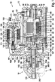
- a starting device 10 is shown in longitudinal section.
- the starting device 10 has, for example, a starter motor 13 and an engagement relay 16.
- the starter motor 13 and the engagement relay 16 are on a common drive end shield 19 attached.
- the starter motor 13 is functionally used to drive a cranking or starter pinion 22 when it is meshed in the ring gear 25 of the internal combustion engine, not shown here.
- the starter motor 13 has a pole tube 28 as a housing, which carries pole shoes 31 on its inner circumference, each of which is wrapped by an excitation winding 34.
- the pole shoes 31 in turn surround an armature 37, which has an armature package 43 made up of lamellae 40 and an armature winding 49 arranged in grooves 46.
- the armature package 43 is pressed onto a drive shaft 44.
- a collector or commutator 52 is also attached, which is made up of individual commutator segments 55, among other things.
- the commutator segments 55 are electrically connected in a known manner to the armature winding 49 in such a way that when the commutator segments 55 are energized by carbon brushes 58, a rotary movement of the armature 37 in the pole tube 28 results.
- a power supply 61 arranged between the engaging relay 16 and the starter motor 13 supplies both the carbon brushes 58 and the excitation winding 34 with power in the switched-on state.
- the drive shaft 44 is supported on the commutator side with a shaft journal 64 in a slide bearing 67, which in turn is held stationary in a commutator bearing cover 70.
- the commutator cover 70 is in turn fastened in the drive end shield 19 by means of tie rods 73 which are arranged distributed over the circumference of the pole tube 28 (screws, for example 2, 3 or 4 pieces).
- the pole tube 28 is supported on the drive end shield 19, and the commutator bearing cover 70 on the pole tube 28.
- a so-called sun gear 80 which is part of a planetary gear 83, adjoins the armature 37 in the drive direction.
- the sun gear 80 is surrounded by several planet gears 86, usually three planet gears 86, which are supported on axle journals 92 by means of roller bearings 89.
- the planet gears 86 roll in a ring gear 95 which is mounted on the outside in the pole tube 28.
- the planet gears 86 are adjoined by a planet carrier 98 in which the axle journals 92 are received.
- the planet carrier 98 is in turn stored in an intermediate bearing 101 and a slide bearing 104 arranged therein.
- the intermediate bearing 101 is designed in such a pot-shaped manner that both the planet carrier 98 and the planet gears 86 are received in it.
- the ring gear 95 is arranged in the cup-shaped intermediate bearing 101, which is ultimately closed with respect to the armature 37 by a cover 107.
- the intermediate bearing 101 is also supported with its outer circumference on the inside of the pole tube 28.
- the armature 37 On the end of the drive shaft 44 facing away from the commutator 52, the armature 37 has a further shaft journal 110, which is likewise received in a sliding bearing 113.
- the slide bearing 113 is in turn received in a central bore of the planet carrier 98.
- the planet carrier 98 is connected in one piece to the output shaft 116.
- This output shaft 116 is supported with its end 119 facing away from the intermediate bearing 101 in a further bearing 122 which is fastened in the drive end shield 19.
- the output shaft 116 is divided into different sections: The section which is arranged in the plain bearing 104 of the intermediate bearing 101 is followed by a section with a so-called straight toothing 125 (internal toothing), which is part of a so-called shaft-hub connection.
- this shaft-hub connection 128 enables a driver 131 to slide axially in a straight line.
- This driver 131 is a sleeve-like extension which is integral with a cup-shaped outer ring 132 of the freewheel 137.
- This freewheel 137 (directional lock) also consists of the inner ring 140, which is arranged radially inside the outer ring 132.
- Clamping bodies 138 are arranged between the inner ring 140 and the outer ring 132.
- the inner ring 140 forms the pinion shaft designed as a separate component, on which the turning or starter pinion 22, which has the helical toothing 143 (external helical toothing), rests non-rotatably, but with an axial adjustment option.
- the starter pinion 22 can alternatively also be designed as a straight-toothed pinion.
- electromagnetically excited pole shoes 31 with excitation winding 34 permanent magnetically excited poles can also be used.
- a spring element 300 which is designed, for example, as a plate spring or helical spring and axially supports the cranking or starter pinion 22.
- the axial relative movement of the cranking or starter pinion 22 on the pinion shaft 140 is on the end face facing away from the spring element 300 limited by a stop device 302, which is described in more detail in the following figures.
- the engagement relay 16 has a bolt 150 which is an electrical contact and which is connected to the positive pole of an electrical starter battery, which is not shown here.
- This bolt 150 is passed through a relay cover 153.
- This relay cover 153 closes off a relay housing 156 which is fastened to the drive end shield 19 by means of several fastening elements 159 (screws).
- a pull-in winding 162 and a so-called holding winding 165 are also arranged in the engagement relay 16.
- the pull-in winding 162 and the holding winding 165 each cause an electromagnetic field in the switched-on state, which flows through the relay housing 156 (made of electromagnetically conductive material), a linearly movable armature 168 and an armature yoke 171.
- the armature 168 carries a push rod 174 which is moved in the direction of a switching pin 177 when the armature 168 is drawn in linearly. With this movement of the push rod 174 to the switching pin 177, the latter is moved from its rest position towards two contacts 180 and 181, so that a contact bridge 184 attached to the contacts 180 and 181 end of the switching pin 177 electrically connects the two contacts 180 and 181 with one another. As a result, electrical power is fed from the bolt 150 via the contact bridge 184 to the power supply 61 and thus to the carbon brushes 58. The starter motor 13 is energized.
- the engagement relay 16 or armature 168 also has the task of using a tension element 187 to move a lever that is rotatably arranged on the drive end shield 19.
- This lever 190 usually designed as a fork lever, with two prongs (not shown here) on its outer circumference, engages two disks 193 and 194 in order to move a driver ring 197 clamped between them to the freewheel 137 against the resistance of the spring 200 and thereby the starting pinion 22 in to mesh the ring gear 25.
- the stop device 302 is shown, via which the axial relative movement of the starter pinion 22 with respect to the pinion shaft 140 is limited.
- the stop device 302 comprises a securing ring on the side opposite the spring element 300 304, which is inserted into a circumferential groove in the outer surface of the pinion shaft 140, and a securing recess 306, which is made as an annular recess in the end face of the starter pinion facing away from the spring element 300.
- a securing ring on the side opposite the spring element 300 304, which is inserted into a circumferential groove in the outer surface of the pinion shaft 140, and a securing recess 306, which is made as an annular recess in the end face of the starter pinion facing away from the spring element 300.
- the starter pinion 22 is axially displaced against the force of the spring element 300 into a removal position in which the locking ring 304 is directly in front of the end face of the starter pinion 22, so that the locking ring 304 is inserted into or removed from the groove in the outer surface of the pinion shaft 140 can be.
- the starter pinion 22 can be seen through the force of the spring element 300 in the axially advanced position in which the locking ring 304 is received in the locking recess 306 which is made in the end face of the starter pinion 22.
- the securing ring 304 is completely in the securing recess 306.
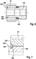
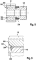
- FIG. 6 to 9 Another exemplary embodiment of a stop device 2 between the starter pinion 22 and a locking ring 304 on the pinion shaft 140 is shown.
- the stop device 302 comprises the securing ring 304, which is received in a circumferential groove in the lateral surface of the pinion shaft 140, and a securing recess 306 which is made in the starter pinion 22 adjacent to the end face.
- the securing ring 304 is completely received in the securing recess 306.
- the securing ring 304 is not in front of the end face of the starter pinion 22, but rather is located in a removal recess 308, which is also made in the starter pinion 22 and directly adjoins the end face of the starter pinion.
- the removal recess 308 is axially directly in front of the securing recess 306 and has a larger diameter than the securing recess 306 on so that how in particular Fig. 7 it can be seen that the securing ring 304 has sufficient radial distance to the inside of the removal recess 308 so that a radial expansion of the securing ring 304 and removal from the groove in the lateral surface of the starter pinion 140 is possible. This allows the securing ring 304 to be removed from within the starter pinion 22 or to be inserted into the groove in the outer surface of the pinion shaft.
Landscapes
- Engineering & Computer Science (AREA)
- Chemical & Material Sciences (AREA)
- Combustion & Propulsion (AREA)
- Mechanical Engineering (AREA)
- General Engineering & Computer Science (AREA)
- Connection Of Motors, Electrical Generators, Mechanical Devices, And The Like (AREA)
- Revetment (AREA)
Description
- Die Erfindung bezieht sich auf eine Startvorrichtung für eine Brennkraftmaschine nach dem Oberbegriff des Anspruches 1.
- In der
DE 10 2008 000 883 A1 wird eine Startvorrichtung für eine Brennkraftmaschine beschrieben, bei der ein Starterritzel axial zwischen einer zurückgezogenen Außerfunktionsposition und einer vorgerückten Antriebsposition verstellbar ist, in welcher das Starterritzel mit dem Zahnkranz einer Brennkraftmaschine kämmt. Das Starterritzel sitzt auf einer Ritzelwelle auf, die über eine Antriebswelle in Drehbewegung versetzt wird. Mittels eines Einrückrelais wird die Ritzelwelle einschließlich Starterritzel axial vorgespurt. Das Starterritzel ist als ein separat von der Ritzelwelle ausgebildetes Bauteil ausgeführt, das drehfest mit der Ritzelwelle gekoppelt ist, jedoch axial auf der Ritzelwelle verschieblich angeordnet ist. Das Starterritzel ist über eine Tellerfeder an einem Absatz der Ritzelwelle abgestützt, wobei auf der der Feder gegenüberliegenden Stirnseite ein Sicherungsring in einer umlaufenden Nut in der Mantelfläche der Ritzelwelle angeordnet ist, der die axiale Verschiebebewegung des Starterritzels auf der Ritzelwelle begrenzt. Um bei hohen Drehzahlen ein Aufspreizen des Sicherungsrings und damit die Gefahr des Lösens des Sicherungsrings zu vermeiden, ist der Sicherungsring von einer stirnseitigen Ausnehmung im Starterritzel übergriffen, wobei in die Ausnehmung zusätzlich ein Sicherungselement eingebracht ist, welches den Sicherungsring radial übergreift. - Zur Montage muss zunächst die Tellerfeder und anschließend das Starterritzel auf die Ritzelwelle aufgeschoben werden. Danach wird der Sicherungsring in die Nut in der Mantelfläche der Ritzelwelle eingesetzt. Als letzter Schritt wird das Sicherungselement in die Ausnehmung eingeführt, um das Aufspreizen des Sicherungsrings bei hohen Drehzahlen zu verhindern.
- Aus der
JP60-114274 U DE 69207927 T2 sind jeweils Startvorrichtungen bekannt, deren Sicherungsring durch einen Anschlag gegen Aufweiten gesichert ist. Aus derJP58-108270 U - Der Erfindung liegt die Aufgabe zugrunde, mit einfachen konstruktiven Maßnahmen die Axialbewegung eines Starterritzels in einer Startvorrichtung für eine Brennkraftmaschine zu begrenzen.
- Diese Aufgabe wird erfindungsgemäß mit den Merkmalen des Anspruches 1 gelöst. Die Unteransprüche geben zweckmäßige Weiterbildungen an.
- Die erfindungsgemäße Startvorrichtung wird zum Starten einer Brennkraftmaschine eingesetzt. Es kann sich um einen frei ausstoßenden Starter oder um einen Maulstarter handeln. Das Starterritzel ist axial zwischen einer Außerfunktionsposition und einer vorgerückten Antriebsposition zu verstellen, in der das Starterritzel in Eingriff mit einem Zahnkranz einer Brennkraftmaschine steht. Das Starterritzel ist gegenüber einem antreibenden Bauteil axial verschieblich angeordnet, um die Vorschubbewegung ausführen zu können. Bei dem antreibenden Bauteil handelt es sich insbesondere um eine Antriebswelle, welche von einem elektrischen Startermotor in Rotation versetzt wird.
- Gegenüber dem antreibenden Bauteil ist das Starterritzel über ein Federelement axial abgestützt, so dass der Impuls beim Vorrücken und einem auftreffenden Zahn-auf-Zahn auf den Zahnkranz der Brennkraftmaschine signifikant reduziert wird. Das Federelement übt auf das Starterritzel eine axiale Federkraft aus, wobei im Falle des Zahn-auf-Zahn-Auftreffens das Federelement zusammengedrückt und Energie im Federelement gespeichert wird. Mit dem Einspuren in den Zahnkranz kann das Starterritzel durch die gespeicherte Federkraft axial bis zum Erreichen der endgültigen Startposition vorrücken.
- Gemäß einer zweckmäßigen Ausführung ist das Starterritzel als ein Steckritzel ausgebildet, das auf eine Ritzelwelle aufschiebbar ist, mit der in der montierten Position das Starterritzel drehfest gekoppelt ist, jedoch eine axiale Relativbewegung ausführen kann. Die Ritzelwelle wird von der motorisch angetriebenen Antriebswelle zum Starten der Brennkraftmaschine in die Drehbewegung versetzt.
- Zur Begrenzung der Axialbewegung des Starterritzels sitzt auf der Welle ein Sicherungsring auf, der einen Anschlag für das Starterritzel bildet. Um zu vermeiden, dass der Sicherungsring bei hohen Umdrehungen sich aufspreizt und von der Welle löst, ist in die Stirnseite des Starterritzels eine Sicherungsausnehmung eingebracht, in die der Sicherungsring einragt. Der Sicherungsring wird radial in seiner Position auf der Welle durch die übergreifende Wandung der Sicherungsausnehmung im Starterritzel fixiert.
- Bei der erfindungsgemäßen Startvorrichtung ist das Starterritzel axial in eine Entnahmeposition verschiebbar, in welcher der Sicherungsring axial außerhalb der Sicherungsausnehmung liegt, so dass der Sicherungsring radial aufgeweitet werden kann. Dies ist insbesondere für Montagezwecke von Bedeutung, da der Sicherungsring üblicherweise im aufgeweiteten Zustand auf die aufnehmende Welle aufgeschoben wird bzw. für einen Wechsel von der Welle entnommen werden muss. Um das Aufweiten des Sicherungsrings in einfacher Weise bewerkstelligen zu können, ist die Startvorrichtung konstruktiv so ausgebildet, dass das Starterritzel in eine axiale Entnahmeposition verstellbar ist, in der das radiale Aufweiten des Sicherungsring ohne Behinderung durch die übergreifende Wandung der Sicherungsausnehmung möglich ist. Diese Ausführung erlaubt die Montage bzw. den Wechsel des Sicherungsrings, ohne dass zusätzliche Bauteile am Starterritzel bzw. der Sicherungsausnehmung erforderlich sind, so wie dies im Stand der Technik der Fall ist, wo ein zusätzliches, ringförmiges Sicherungselement nachträglich in die Sicherungsausnehmung an der Stirnseite des Starterritzels zur Begrenzung des radialen Aufweitens des Sicherungsrings erforderlich ist. Bei der erfindungsgemäßen Ausführung kann auf ein derartiges, ringförmiges Sicherungselement verzichtet werden, so dass insgesamt eine konstruktiv einfachere Ausführung gegeben ist. Es muss lediglich sichergestellt werden, dass das Starterritzel axial in die Entnahmeposition verschiebbar ist.
- Es kommen grundsätzlich verschiedene Möglichkeiten der Positionierung des Sicherungsrings axial außerhalb der Sicherungsausnehmung in der Entnahmeposition in Betracht. Zum einen kann der Sicherungsring in der Entnahmeposition der Stirnseite des Starterritzels axial vorgelagert sein. Diese konstruktiv einfache Ausführung erfordert lediglich, dass das Starterritzel zum Erreichen der Entnahmeposition axial so weit verschoben wird, dass der Sicherungsring der Stirnseite des Starterritzels axial vorgelagert ist, so dass ein radiales Aufweiten des Sicherungsrings ohne Weiteres möglich ist.
- Gemäß einer erfindungsgemäßen Ausführung ist vorgesehen, dass sich innerhalb des Starterritzels an die Sicherungsausnehmung eine Entnahmeausnehmung anschließt, welche einen größeren Durchmesser als die Sicherungsausnehmung aufweist, so dass der Sicherungsring radial aufgeweitet werden kann, auch wenn sich der Sicherungsring innerhalb des Starterritzels befindet. Die Entnahmeausnehmung schließt sich zweckmäßigerweise unmittelbar benachbart zur Stirnseite des Starterritzels an und ist ebenso wie die Sicherungsausnehmung ringförmig ausgebildet. Diese Ausführung hat den Vorteil, dass die Startvorrichtung in Achsrichtung klein bauend ausgeführt sein kann, da der Bauraum für das Erreichen der Entnahmeposition innerhalb der axialen Erstreckung des Starterritzels liegt. Die axiale Erstreckung der Entnahmeausnehmung kann hierbei zumindest annähernd der Dicke des Sicherungsrings entsprechen, wobei die Entnahmeausnehmung eine kleinere axiale Erstreckung als die Dicke des Sicherungsrings aufweisen muss, so dass der Sicherungsring mit dem Erreichen der Entnahmeposition teilweise über die Stirnseite des Starterritzels hinausragt.
- Die Sicherungsausnehmung weist zweckmäßigerweise einen Durchmesser auf, der so bemessen ist, dass ein Ringspalt zwischen der Außenseite des Sicherungsrings und der Innenseite der Sicherungsausnehmung besteht. Möglich ist aber auch ein Durchmesser, der so bemessen ist, dass die Außenseite des Sicherungsrings in Kontakt mit der Innenseite der Sicherungsausnehmung steht.
- Zum Erreichen der Entnahmeposition ist das Starterritzel zweckmäßigerweise gegen die Kraft des Federelementes zu verschieben. Dadurch ist sichergestellt, dass das Starterritzel ohne äußere Einwirkung durch die Kraft des Federelementes axial in die sichernde Position vorgeschoben ist, in welcher der Sicherungsring innerhalb der Sicherungsausnehmung im Starterritzel liegt. Zur axialen Sicherung kann in die Mantelfläche der Welle eine umlaufende Nut eingebracht sein, in welche der Sicherungsring eingesetzt ist. Die den Sicherungsring umgreifende Sicherungsausnehmung vermeidet, dass der Sicherungsring bei hohen Drehzahlen durch Aufweiten aus der Nut herausspringt und sich von der Welle löst.
- Weitere Vorteile und zweckmäßige Ausführungen sind den weiteren Ansprüchen, der Figurenbeschreibung und den Zeichnungen zu entnehmen. Es zeigen:
- Fig. 1
- einen Starter für eine Brennkraftmaschine in einem Längsschnitt,
- Fig. 2
- einen Schnitt durch das Starterritzel und die Ritzelwelle, auf der das Starterritzel aufsitzt, mit einem Sicherungsring auf der Ritzelwelle, welcher die axiale Vorschubbewegung des Starterritzels begrenzt, wobei das Starterritzel in einer Entnahmeposition steht, in welcher der Sicherungsring der Stirnseite des Starterritzels axial vorgelagert ist,
- Fig. 3
- in vergrößerter Darstellung der Bereich zwischen Starterritzel und Ritzelwelle mit dem Sicherungsring,
- Fig. 4
- eine
Fig. 2 entsprechende Darstellung, jedoch mit dem Starterritzel in der durch die Kraft eines Federelementes vorgeschobenen Position, in welcher sich der Sicherungsring in einer Sicherungsausnehmung befindet, die in die Stirnseite des Starterritzels eingebracht ist, - Fig. 5
- in vergrößerter Darstellung das Starterritzel und die Ritzelwelle mit dem Sicherungsring in der Sicherungsausnehmung,
- Fig. 6 bis Fig. 9
- ein weiteres Ausführungsbeispiel mit Darstellungen gemäß den
Fig. 2 bis 5 , jedoch mit einer zusätzlichen Entnahmeausnehmung im Starterritzel, die sich unmittelbar an die Sicherungsausnehmung zur Aufnahme des Sicherungsrings anschließt. - In den Figuren sind gleiche Bauteile mit gleichen Bezugszeichen versehen.
- In
Fig. 1 ist eine Startvorrichtung 10 im Längsschnitt dargestellt. Die Startvorrichtung 10 weist beispielsweise einen Startermotor 13 und ein Einrückrelais 16 auf. Der Startermotor 13 und das Einrückrelais 16 sind an einem gemeinsamen Antriebslagerschild 19 befestigt. Der Startermotor 13 dient funktionell dazu, ein Andreh- bzw. Starterritzel 22 anzutreiben, wenn es im Zahnkranz 25 der hier nicht dargestellten Brennkraftmaschine eingespurt ist. - Der Startermotor 13 weist als Gehäuse ein Polrohr 28 auf, das an seinem Innenumfang Polschuhe 31 trägt, die jeweils von einer Erregerwicklung 34 umwickelt sind. Die Polschuhe 31 umgeben wiederum einen Anker 37, der ein aus Lamellen 40 aufgebautes Ankerpaket 43 und eine in Nuten 46 angeordnete Ankerwicklung 49 aufweist. Das Ankerpaket 43 ist auf eine Antriebswelle 44 aufgepresst. An dem Andrehritzel 22 abgewandten Ende der Antriebswelle 44 ist des Weiteren ein Kollektor bzw. Kommutator 52 angebracht, der unter anderem aus einzelnen Kommutatorlamellen 55 aufgebaut ist. Die Kommutatorlamellen 55 sind in bekannter Weise mit der Ankerwicklung 49 derartig elektrisch verbunden, dass sich bei Bestromung der Kommutatorlamellen 55 durch Kohlebürsten 58 eine Drehbewegung des Ankers 37 im Polrohr 28 ergibt. Eine zwischen dem Einspurrelais 16 und dem Startermotor 13 angeordnete Stromzuführung 61 versorgt im Einschaltzustand sowohl die Kohlebürsten 58 als auch die Erregerwicklung 34 mit Strom. Die Antriebswelle 44 ist kommutatorseitig mit einem Wellenzapfen 64 in einem Gleitlager 67 abgestützt, welches wiederum in einem Kommutatorlagerdeckel 70 ortsfest gehalten ist. Der Kommutatordeckel 70 wiederum wird mittels Zuganker 73, die über den Umfang des Polrohrs 28 verteilt angeordnet sind (Schrauben, beispielsweise 2, 3 oder 4 Stück) im Antriebslagerschild 19 befestigt. Es stützt sich dabei das Polrohr 28 am Antriebslagerschild 19 ab, und der Kommutatorlagerdeckel 70 am Polrohr 28.
- In Antriebsrichtung schließt sich an den Anker 37 ein sogenanntes Sonnenrad 80 an, das Teil eines Planetengetriebes 83 ist. Das Sonnenrad 80 ist von mehreren Planetenrädern 86 umgeben, üblicherweise drei Planetenräder 86, die mittels Wälzlager 89 auf Achszapfen 92 abgestützt sind. Die Planetenräder 86 wälzen in einem Hohlrad 95 ab, das im Polrohr 28 außenseitig gelagert ist. In Richtung zur Abtriebsseite schließt sich an die Planetenräder 86 ein Planetenträger 98 an, in dem die Achszapfen 92 aufgenommen sind. Der Planetenträger 98 wird wiederum in einem Zwischenlager 101 und einem darin angeordneten Gleitlager 104 gelagert. Das Zwischenlager 101 ist derartig topfförmig gestaltet, dass in diesem sowohl der Planetenträger 98, als auch die Planetenräder 86 aufgenommen sind. Desweiteren ist im topfförmigen Zwischenlager 101 das Hohlrad 95 angeordnet, das letztlich durch einen Deckel 107 gegenüber dem Anker 37 geschlossen ist. Auch das Zwischenlager 101 stützt sich mit seinem Außenumfang an der Innenseite des Polrohrs 28 ab. Der Anker 37 weist auf dem vom Kommutator 52 abgewandten Ende der Antriebswelle 44 einen weiteren Wellenzapfen 110 auf, der ebenfalls in einem Gleitlager 113 aufgenommen ist, ab. Das Gleitlager 113 wiederum ist in einer zentralen Bohrung des Planetenträgers 98 aufgenommen. Der Planetenträger 98 ist einstückig mit der Abtriebswelle 116 verbunden. Diese Abtriebswelle 116 ist mit ihrem vom Zwischenlager 101 abgewandten Ende 119 in einem weiteren Lager 122, welches im Antriebslagerschild 19 befestigt ist, abgestützt. Die Abtriebswelle 116 ist in verschiedene Abschnitte aufgeteilt: So folgt dem Abschnitt, der im Gleitlager 104 des Zwischenlagers 101 angeordnet ist, ein Abschnitt mit einer sogenannten Geradverzahnung 125 (Innenverzahnung), die Teil einer sogenannten Wellen-Nabe-Verbindung ist. Diese Welle-Nabe-Verbindung 128 ermöglicht in diesem Fall das axial geradlinige Gleiten eines Mitnehmers 131. Dieser Mitnehmer 131 ist ein hülsenartiger Fortsatz, der einstückig mit einem topfförmigen Außenring 132 des Freilaufs 137 ist. Dieser Freilauf 137 (Richtgesperre) besteht des Weiteren aus dem Innenring 140, der radial innerhalb des Außenrings 132 angeordnet ist. Zwischen dem Innenring 140 und dem Außenring 132 sind Klemmkörper 138 angeordnet. Diese Klemmkörper 138 verhindern in Zusammenwirkung mit dem Innen- und dem Außenring eine Relativdrehung zwischen dem Außenring und dem Innenring in einer zweiten Richtung. Mit anderen Worten: Der Freilauf 137 ermöglicht eine Relativbewegung zwischen Innenring 140 und Außenring 132 nur in eine Richtung. Im Ausführungsbeispiel bildet der Innenring 140 die als separates Bauteil ausgeführte Ritzelwelle, auf der das Andreh- bzw. Starterritzel 22, das die Schrägverzahnung 143 (Außenschrägverzahnung) aufweist, drehfest, jedoch mit axialer Stellmöglichkeit aufsitzt. Das Andrehritzel 22 kann alternativ auch als geradverzahntes Ritzel ausgeführt sein. Statt elektromagnetisch erregter Polschuhe 31 mit Erregerwicklung 34 können auch permanentmagnetisch erregte Pole verwendet werden.
- Zwischen dem Andreh- bzw. Starterritzel 22 und einem radial erweiterten Bund der Ritzelwelle 140 befindet sich ein Federelement 300, das beispielsweise als Tellerfeder oder Schraubenfeder ausgebildet ist und das Andreh- bzw. Starterritzel 22 axial abstützt. Die axiale Relativbewegung des Andreh- bzw. Starterritzels 22 auf der Ritzelwelle 140 ist auf der dem Federelement 300 abgewandten Stirnseite von einer Anschlagseinrichtung 302 begrenzt, die in den folgenden Figuren näher beschrieben wird.
- Nachfolgend wird auf den Einspurmechanismus eingegangen. Das Einrückrelais 16 weist einen Bolzen 150 auf, der ein elektrischer Kontakt ist und der an den Pluspol einer elektrischen Starterbatterie, die hier nicht dargestellt ist, angeschlossen ist. Dieser Bolzen 150 ist durch einen Relaisdeckel 153 hindurchgeführt. Dieser Relaisdeckel 153 schließt ein Relaisgehäuse 156 ab, das mittels mehrerer Befestigungselemente 159 (Schrauben) am Antriebslagerschild 19 befestigt ist. Im Einrückrelais 16 ist weiterhin eine Einzugswicklung 162 und eine sogenannte Haltewicklung 165 angeordnet. Die Einzugswicklung 162 und die Haltewicklung 165 bewirken beide jeweils im eingeschalteten Zustand ein elektromagnetisches Feld, welches sowohl das Relaisgehäuse 156 (aus elektromagnetisch leitfähigem Material), einen linear beweglichen Anker 168 und einen Ankerrückschluss 171 durchströmt. Der Anker 168 trägt eine Schubstange 174, die beim linearen Einzug des Ankers 168 in Richtung zu einem Schaltbolzen 177 bewegt wird. Mit dieser Bewegung der Schubstange 174 zum Schaltbolzen 177 wird dieser aus seiner Ruhelage in Richtung zu zwei Kontakten 180 und 181 bewegt, so dass eine am zu den Kontakten 180 und 181 Ende des Schaltbolzens 177 angebrachte Kontaktbrücke 184 beide Kontakte 180 und 181 elektrisch miteinander verbindet. Dadurch wird vom Bolzen 150 elektrische Leistung über die Kontaktbrücke 184 hinweg zur Stromzuführung 61 und damit zu den Kohlebürsten 58 geführt. Der Startermotor 13 wird dabei bestromt.
- Das Einrückrelais 16 bzw. der Anker 168 hat darüber hinaus die Aufgabe, mit einem Zugelement 187 einen dem Antriebslagerschild 19 drehbeweglich angeordneten Hebel zu bewegen. Dieser Hebel 190, üblicherweise als Gabelhebel ausgeführt, umgreift mit zwei hier nicht dargestellten Zinken an ihrem Außenumfang zwei Scheiben 193 und 194, um einen zwischen diesen eingeklemmten Mitnehmerring 197 zum Freilauf 137 hin gegen den Widerstand der Feder 200 zu bewegen und dadurch das Andrehritzel 22 in den Zahnkranz 25 einzuspuren.
- In den
Fig. 2 bis 5 ist in einem ersten Ausführungsbeispiel die Anschlagseinrichtung 302 dargestellt, über die die axiale Relativbewegung des Starterritzels 22 gegenüber der Ritzelwelle 140 begrenzt ist. Die Anschlagseinrichtung 302 umfasst auf der dem Federelement 300 gegenüberliegenden Seite einen Sicherungsring 304, der in eine umlaufende Nut in der Mantelfläche der Ritzelwelle 140 eingesetzt ist, sowie eine Sicherungsausnehmung 306, die als ringförmige Ausnehmung in die dem Federelement 300 abgewandten Stirnseite des Starterritzels eingebracht ist. In denFig. 2 und 3 ist das Starterritzel 22 axial gegen die Kraft des Federelementes 300 in eine Entnahmeposition verstellt, in der der Sicherungsring 304 der Stirnseite des Starterritzels 22 unmittelbar vorgelagert ist, so dass der Sicherungsring 304 in die Nut in der Mantelfläche der Ritzelwelle 140 eingesetzt bzw. aus dieser entnommen werden kann. - In den
Fig. 4 und 5 ist dagegen das Starterritzel 22 durch die Kraft des Federelementes 300 in der axial vorgerückten Position zu sehen, in welcher der Sicherungsring 304 in der Sicherungsausnehmung 306, welche in die Stirnseite des Starterritzels 22 eingebracht ist, aufgenommen ist. Wie der vergrößerten Darstellung gemäßFig. 5 zu entnehmen, befindet sich in der Anschlags- bzw. Sicherungsposition der Sicherungsring 304 vollständig in der Sicherungsausnehmung 306. Zwischen der radialen Außenfläche des Sicherungsrings 304 und der radial umgreifenden Innenseite der Ausnehmung 306 befindet sich ein kleiner Ringspalt, wobei gegebenenfalls auch Ausführungen in Betracht kommen, in denen kein Ringspalt besteht, so dass die Außenseite des Sicherungsrings 304 unmittelbar auf Kontakt zur Innenwand der Sicherungsausnehmung 306 liegt. - In den
Fig. 6 bis 9 ist ein weiteres Ausführungsbeispiel für eine Anschlagseinrichtung 2 zwischen dem Starterritzel 22 und einem Sicherungsring 304 auf der Ritzelwelle 140 dargestellt. Wie im vorangegangenen Ausführungsbeispiel umfasst die Anschlagseinrichtung 302 den Sicherungsring 304, der in einer umlaufenden Nut in der Mantelfläche der Ritzelwelle 140 aufgenommen ist, sowie eine Sicherungsausnehmung 306, die benachbart zur Stirnseite in das Starterritzel 22 eingebracht ist. In der Anschlagsposition gemäß denFig. 8 und 9 ist der Sicherungsring 304 vollständig in der Sicherungsausnehmung 306 aufgenommen. In der Entnahmeposition gemäß denFig. 6 und 7 liegt dagegen im Unterschied zum vorangegangenen Ausführungsbeispiel der Sicherungsring 304 nicht vor der Stirnseite des Starterritzels 22, sondern befindet sich vielmehr in einer Entnahmeausnehmung 308, die ebenfalls in das Starterritzel 22 eingebracht ist und sich unmittelbar an die Stirnseite des Starterritzels anschließt. Die Entnahmeausnehmung 308 ist der Sicherungsausnehmung 306 axial direkt vorgelagert und weist einen größeren Durchmesser als die Sicherungsausnehmung 306 auf, so dass, wie insbesondereFig. 7 zu entnehmen ist, der Sicherungsring 304 radial genügend Abstand zur Innenseite der Entnahmeausnehmung 308 aufweist, so dass ein radiales Aufweiten des Sicherungsringes 304 und Entnehmen aus der Nut in der Mantelfläche des Starterritzels 140 möglich ist. Dies erlaubt es, den Sicherungsring 304 innerhalb des Starterritzels 22 zu entnehmen bzw. in die Nut in der Mantelfläche der Ritzelwelle einzusetzen.
Claims (5)
- Startvorrichtung für eine Brennkraftmaschine,
mit einem Starterritzel (22), das axial zwischen einer Außerfunktionsposition und einer vorgerückten Antriebsposition verstellbar ist und auf einer Welle aufsitzt,
mit einem auf der Welle aufsitzenden Sicherungsring (304) zur Begrenzung der Axialbewegung des Starterritzels (22),
wobei in die Stirnseite des Starterritzels (22) eine Sicherungsausnehmung (306) eingebracht ist, in die der Sicherungsring (304) einragt und die den Sicherungsring (304) radial in seiner Position auf der Welle fixiert,
wobei das Starterritzel (22) axial in eine Entnahmeposition verschiebbar ist, in der der Sicherungsring (304) axial außerhalb der Sicherungsausnehmung (306) liegt und radial aufgeweitet werden kann,
wobei sich innerhalb des Starterritzels an die Sicherungsausnehmung (306) eine Entnahmeausnehmung (308) anschließt, die in das Starterritzel (22) eingebracht ist und einen größeren Durchmesser als die Sicherungsausnehmung (306) aufweist,
wobei die Entnahmeausnehmung (308) unmittelbar benachbart zur Stirnseite im Starterritzel (22) angeordnet ist,
dadurch gekennzeichnet, dass die Entnahmeausnehmung eine kleinere axiale Erstreckung aufweist als die Dicke des Sicherungsrings. - Startvorrichtung nach Anspruch 1, dadurch gekennzeichnet, dass die Entnahmeausnehmung (308) ringförmig ausgebildet ist.
- Startvorrichtung nach einem der Ansprüche 1 bis 2, dadurch gekennzeichnet, dass das Starterritzel (22) gegen die Kraft eines Federelements (300) in die Entnahmeposition verschiebbar ist.
- Startvorrichtung nach einem der Ansprüche 1 bis 3, dadurch gekennzeichnet, dass in die Welle eine Nut zur Aufnahme der Sicherungsrings (304) eingebracht ist.
- Startvorrichtung nach einem der Ansprüche 1 bis 4, dadurch gekennzeichnet, dass das Starterritzel (22) auf einer Ritzelwelle (140) aufsitzt und axial beweglich auf der Ritzelwelle (140) gelagert ist, wobei der Sicherungsring (304) auf der Ritzelwelle (140) angeordnet ist.
Applications Claiming Priority (2)
| Application Number | Priority Date | Filing Date | Title |
|---|---|---|---|
| DE102011017534.2A DE102011017534B4 (de) | 2011-04-26 | 2011-04-26 | Startvorrichtung für eine Brennkraftmaschine |
| PCT/EP2012/056784 WO2012146495A2 (de) | 2011-04-26 | 2012-04-13 | Startvorrichtung für eine brennkraftmaschine |
Publications (2)
| Publication Number | Publication Date |
|---|---|
| EP2702263A2 EP2702263A2 (de) | 2014-03-05 |
| EP2702263B1 true EP2702263B1 (de) | 2021-06-02 |
Family
ID=45998298
Family Applications (1)
| Application Number | Title | Priority Date | Filing Date |
|---|---|---|---|
| EP12715926.7A Active EP2702263B1 (de) | 2011-04-26 | 2012-04-13 | Startvorrichtung für eine brennkraftmaschine |
Country Status (7)
| Country | Link |
|---|---|
| US (1) | US9617964B2 (de) |
| EP (1) | EP2702263B1 (de) |
| CN (1) | CN103649523B (de) |
| DE (1) | DE102011017534B4 (de) |
| HU (1) | HUE055359T2 (de) |
| MX (1) | MX349535B (de) |
| WO (1) | WO2012146495A2 (de) |
Families Citing this family (8)
| Publication number | Priority date | Publication date | Assignee | Title |
|---|---|---|---|---|
| DE102011017534B4 (de) | 2011-04-26 | 2020-06-04 | Seg Automotive Germany Gmbh | Startvorrichtung für eine Brennkraftmaschine |
| DE102013204430B4 (de) * | 2013-03-14 | 2021-05-12 | Seg Automotive Germany Gmbh | Startvorrichtung für eine Brennkraftmaschine |
| DE102014217350B4 (de) * | 2014-08-29 | 2022-03-24 | Seg Automotive Germany Gmbh | Elektrische Maschine mit einem als Antriebslager ausgebildeten Gehäuse und darin gelagertem Hohlrad |
| CN106837650B (zh) * | 2015-12-07 | 2021-05-11 | 索恩格汽车德国有限责任公司 | 起动机及其中驱动齿轮结构的组装方法 |
| WO2017175597A1 (ja) * | 2016-04-06 | 2017-10-12 | 日立オートモティブシステムズ株式会社 | スタータ |
| FR3058475A1 (fr) * | 2016-11-07 | 2018-05-11 | Valeo Equipements Electriques Moteur | Lanceur pour demarreur de vehicule automobile a moteur thermique |
| FR3081939B1 (fr) * | 2018-06-01 | 2021-05-21 | Valeo Equip Electr Moteur | Lanceur pour demarreur de vehicule automobile |
| CN110821731B (zh) * | 2019-12-03 | 2022-03-22 | 福建永强力加动力设备有限公司 | 一种启动马达 |
Citations (5)
| Publication number | Priority date | Publication date | Assignee | Title |
|---|---|---|---|---|
| DE102006051578A1 (de) * | 2006-11-02 | 2008-05-08 | Robert Bosch Gmbh | Starter zum Andrehen einer Brennkraftmaschine mit Ritzelwellenabstützung |
| DE102008000883A1 (de) * | 2008-03-31 | 2009-10-01 | Robert Bosch Gmbh | Startvorrichtung |
| DE102008054979A1 (de) * | 2008-12-19 | 2010-06-24 | Robert Bosch Gmbh | Verfahren und Vorrichtung für Start-Stopp-Anlagen von Brennkraftmaschinen in Kraftfahrzeugen |
| WO2011114052A2 (fr) * | 2010-03-19 | 2011-09-22 | Valeo Equipements Electriques Moteur | Demarreur de moteur thermique a pignon sortant |
| EP2436913A1 (de) * | 2010-09-30 | 2012-04-04 | Robert Bosch GmbH | Starter für eine Brennkraftmaschine |
Family Cites Families (25)
| Publication number | Priority date | Publication date | Assignee | Title |
|---|---|---|---|---|
| US1971740A (en) * | 1932-01-30 | 1934-08-28 | Eclipse Machine Co | Rebound check for engine starters |
| US2710606A (en) * | 1954-05-18 | 1955-06-14 | Charles Greif Raible | Hydraulic starter |
| US3490255A (en) * | 1967-12-19 | 1970-01-20 | Gen Motors Corp | Vehicle control locking system |
| US4330713A (en) * | 1980-04-16 | 1982-05-18 | Eaton Stamping Company | Cushioned starter pinion |
| JPS58108270A (ja) | 1981-12-21 | 1983-06-28 | Pilot Ink Co Ltd | マ−キングペン用インキ |
| JPS58108270U (ja) * | 1982-01-18 | 1983-07-23 | 三菱電機株式会社 | 機関始動装置 |
| JPS60114274A (ja) | 1983-11-25 | 1985-06-20 | 東急車輌製造株式会社 | 消防車用タレツトノズルの方向制御システム |
| JPS60114274U (ja) * | 1984-01-12 | 1985-08-02 | 三菱電機株式会社 | スタ−タ |
| JPS6247771A (ja) | 1985-08-27 | 1987-03-02 | Nec Corp | スケジユ−ル入力編集方法 |
| JPS6247771U (de) * | 1985-09-10 | 1987-03-24 | ||
| JPH0744811B2 (ja) * | 1989-08-31 | 1995-05-15 | 三菱電機株式会社 | スタータ |
| JPH04104164U (ja) * | 1991-02-18 | 1992-09-08 | 三菱電機株式会社 | スタータ装置 |
| JPH06213114A (ja) * | 1993-01-20 | 1994-08-02 | Hitachi Ltd | ピニオンストッパー装置 |
| FR2772433B1 (fr) * | 1997-12-17 | 2000-02-04 | Valeo Equip Electr Moteur | Demarreur de vehicule automobile comportant un lanceur perfectionne |
| CZ293544B6 (cs) * | 2001-04-10 | 2004-05-12 | Magnetonáa@Ás | Spouštěč pro spalovací motory |
| JP2004183586A (ja) * | 2002-12-05 | 2004-07-02 | Denso Corp | スタータ |
| FR2850136B1 (fr) * | 2003-01-21 | 2006-05-26 | Valeo Equip Electr Moteur | Procede de montage d'un anneau d'arret sur un arbre de demarreur electrique muni d'un lanceur avec butee sur cannelures |
| CN101044314A (zh) * | 2004-10-20 | 2007-09-26 | 株式会社美姿把 | 带惰轮的起动电动机 |
| US20060230599A1 (en) * | 2005-04-18 | 2006-10-19 | Kabushiki Kaisha Toshiba | Clamp ring detaching method, clamp ring detaching tool, and method of manufacturing magnetic disk device |
| JP2007071164A (ja) * | 2005-09-08 | 2007-03-22 | Denso Corp | スタータ |
| DE112006002520B4 (de) * | 2005-09-21 | 2018-01-04 | Mitsuba Corp. | Anlasser |
| DE102008042525A1 (de) * | 2008-10-01 | 2010-04-08 | Robert Bosch Gmbh | Startvorrichtung |
| US9175657B2 (en) * | 2011-03-31 | 2015-11-03 | Mitsubishi Electric Corporation | Engine starting device |
| DE102011017534B4 (de) | 2011-04-26 | 2020-06-04 | Seg Automotive Germany Gmbh | Startvorrichtung für eine Brennkraftmaschine |
| JP2013083176A (ja) * | 2011-10-07 | 2013-05-09 | Denso Corp | スタータ |
-
2011
- 2011-04-26 DE DE102011017534.2A patent/DE102011017534B4/de not_active Expired - Fee Related
-
2012
- 2012-04-13 CN CN201280020584.8A patent/CN103649523B/zh not_active Expired - Fee Related
- 2012-04-13 US US14/113,468 patent/US9617964B2/en not_active Expired - Fee Related
- 2012-04-13 WO PCT/EP2012/056784 patent/WO2012146495A2/de not_active Ceased
- 2012-04-13 EP EP12715926.7A patent/EP2702263B1/de active Active
- 2012-04-13 HU HUE12715926A patent/HUE055359T2/hu unknown
- 2012-09-23 MX MX2013012515A patent/MX349535B/es active IP Right Grant
Patent Citations (5)
| Publication number | Priority date | Publication date | Assignee | Title |
|---|---|---|---|---|
| DE102006051578A1 (de) * | 2006-11-02 | 2008-05-08 | Robert Bosch Gmbh | Starter zum Andrehen einer Brennkraftmaschine mit Ritzelwellenabstützung |
| DE102008000883A1 (de) * | 2008-03-31 | 2009-10-01 | Robert Bosch Gmbh | Startvorrichtung |
| DE102008054979A1 (de) * | 2008-12-19 | 2010-06-24 | Robert Bosch Gmbh | Verfahren und Vorrichtung für Start-Stopp-Anlagen von Brennkraftmaschinen in Kraftfahrzeugen |
| WO2011114052A2 (fr) * | 2010-03-19 | 2011-09-22 | Valeo Equipements Electriques Moteur | Demarreur de moteur thermique a pignon sortant |
| EP2436913A1 (de) * | 2010-09-30 | 2012-04-04 | Robert Bosch GmbH | Starter für eine Brennkraftmaschine |
Also Published As
| Publication number | Publication date |
|---|---|
| WO2012146495A2 (de) | 2012-11-01 |
| EP2702263A2 (de) | 2014-03-05 |
| WO2012146495A3 (de) | 2013-01-17 |
| MX349535B (es) | 2017-08-02 |
| DE102011017534A1 (de) | 2012-10-31 |
| CN103649523A (zh) | 2014-03-19 |
| MX2013012515A (es) | 2014-02-03 |
| DE102011017534B4 (de) | 2020-06-04 |
| US9617964B2 (en) | 2017-04-11 |
| CN103649523B (zh) | 2017-05-03 |
| HUE055359T2 (hu) | 2021-11-29 |
| US20140060472A1 (en) | 2014-03-06 |
Similar Documents
| Publication | Publication Date | Title |
|---|---|---|
| DE102009027117B4 (de) | Elektrischer Antrieb sowie Verfahren zur Montage eben dieses Antriebs | |
| DE102011017534B4 (de) | Startvorrichtung für eine Brennkraftmaschine | |
| EP2622208A2 (de) | Anlasser für eine brennkraftmaschine mit einem dämpfungsanschlag für das einspurgetriebe | |
| EP2172645B1 (de) | Startvorrichtung | |
| EP2677161B1 (de) | Starterrelais für eine Startvorrichtung | |
| EP2436913B1 (de) | Starter für eine Brennkraftmaschine | |
| WO2009095115A1 (de) | Verfahren zum betreiben einer startvorrichtung sowie startvorrichtung | |
| DE102013102241A1 (de) | Elektromagnetische Stellvorrichtung, insbesondere zur Nockenwellenverstellung einer Brennkraftmaschine | |
| EP2375055B1 (de) | Abdeckring für Startvorrichtung | |
| WO2011012472A2 (de) | Elektromotor mit permanentmagnet-erregung | |
| DE102014210687A1 (de) | Elektromagnetisches Relais, insbesondere Starterrelais für eine Startvorrichtung | |
| EP2472101B1 (de) | Vorrichtung zur Sicherung eines Ritzels | |
| EP2887508B1 (de) | Elektromotor, insbesondere Startermotor für eine Startvorrichtung | |
| DE102010040527B4 (de) | Starter für eine Brennkraftmaschine | |
| DE102014224581A1 (de) | Elektromagnetisches Relais, insbesondere Starterrelais für eine Startvorrichtung | |
| DE102015225872A1 (de) | Elektromagnetisches Relais, insbesondere Starterrelais für eine Startvorrichtung | |
| DE102010063507A1 (de) | Geräuschoptimierte Startervorrichtung | |
| DE102013222629A1 (de) | Kommutierungseinrichtung in einer elektrischen Maschine | |
| DE102015222319A1 (de) | Starterrelais für eine Startvorrichtung | |
| DE102014224584A1 (de) | Elektromagnetisches Relais, insbesondere Starterrelais für eine Startvorrichtung | |
| EP2413473A2 (de) | Elektrische Maschine | |
| WO2011107379A1 (de) | Starter für eine brennkraftmaschine | |
| DE102014224589A1 (de) | Elektromagnetisches Relais, insbesondere Starterrelais für eine Startvorrichtung | |
| DE102014225520A1 (de) | Kommutierungseinrichtung für eine elektrische Maschine |
Legal Events
| Date | Code | Title | Description |
|---|---|---|---|
| PUAI | Public reference made under article 153(3) epc to a published international application that has entered the european phase |
Free format text: ORIGINAL CODE: 0009012 |
|
| 17P | Request for examination filed |
Effective date: 20131126 |
|
| AK | Designated contracting states |
Kind code of ref document: A2 Designated state(s): AL AT BE BG CH CY CZ DE DK EE ES FI FR GB GR HR HU IE IS IT LI LT LU LV MC MK MT NL NO PL PT RO RS SE SI SK SM TR |
|
| DAX | Request for extension of the european patent (deleted) | ||
| RAP1 | Party data changed (applicant data changed or rights of an application transferred) |
Owner name: SEG AUTOMOTIVE GERMANY GMBH |
|
| STAA | Information on the status of an ep patent application or granted ep patent |
Free format text: STATUS: EXAMINATION IS IN PROGRESS |
|
| 17Q | First examination report despatched |
Effective date: 20191114 |
|
| RIC1 | Information provided on ipc code assigned before grant |
Ipc: F02N 11/00 20060101ALN20201016BHEP Ipc: F02N 15/04 20060101ALN20201016BHEP Ipc: F02N 15/00 20060101AFI20201016BHEP Ipc: F02N 15/06 20060101ALI20201016BHEP Ipc: F02N 15/10 20060101ALI20201016BHEP |
|
| REG | Reference to a national code |
Ref country code: DE Ref legal event code: R079 Ref document number: 502012016779 Country of ref document: DE Free format text: PREVIOUS MAIN CLASS: F02N0015060000 Ipc: F02N0015000000 |
|
| GRAP | Despatch of communication of intention to grant a patent |
Free format text: ORIGINAL CODE: EPIDOSNIGR1 |
|
| STAA | Information on the status of an ep patent application or granted ep patent |
Free format text: STATUS: GRANT OF PATENT IS INTENDED |
|
| INTG | Intention to grant announced |
Effective date: 20201211 |
|
| RIC1 | Information provided on ipc code assigned before grant |
Ipc: F02N 15/04 20060101ALN20201130BHEP Ipc: F02N 11/00 20060101ALN20201130BHEP Ipc: F02N 15/06 20060101ALI20201130BHEP Ipc: F02N 15/00 20060101AFI20201130BHEP Ipc: F02N 15/10 20060101ALI20201130BHEP |
|
| GRAS | Grant fee paid |
Free format text: ORIGINAL CODE: EPIDOSNIGR3 |
|
| GRAA | (expected) grant |
Free format text: ORIGINAL CODE: 0009210 |
|
| STAA | Information on the status of an ep patent application or granted ep patent |
Free format text: STATUS: THE PATENT HAS BEEN GRANTED |
|
| REG | Reference to a national code |
Ref country code: CH Ref legal event code: EP |
|
| AK | Designated contracting states |
Kind code of ref document: B1 Designated state(s): AL AT BE BG CH CY CZ DE DK EE ES FI FR GB GR HR HU IE IS IT LI LT LU LV MC MK MT NL NO PL PT RO RS SE SI SK SM TR |
|
| REG | Reference to a national code |
Ref country code: GB Ref legal event code: FG4D Free format text: NOT ENGLISH |
|
| REG | Reference to a national code |
Ref country code: AT Ref legal event code: REF Ref document number: 1398668 Country of ref document: AT Kind code of ref document: T Effective date: 20210615 |
|
| REG | Reference to a national code |
Ref country code: IE Ref legal event code: FG4D Free format text: LANGUAGE OF EP DOCUMENT: GERMAN |
|
| REG | Reference to a national code |
Ref country code: DE Ref legal event code: R096 Ref document number: 502012016779 Country of ref document: DE |
|
| REG | Reference to a national code |
Ref country code: LT Ref legal event code: MG9D |
|
| PG25 | Lapsed in a contracting state [announced via postgrant information from national office to epo] |
Ref country code: FI Free format text: LAPSE BECAUSE OF FAILURE TO SUBMIT A TRANSLATION OF THE DESCRIPTION OR TO PAY THE FEE WITHIN THE PRESCRIBED TIME-LIMIT Effective date: 20210602 Ref country code: LT Free format text: LAPSE BECAUSE OF FAILURE TO SUBMIT A TRANSLATION OF THE DESCRIPTION OR TO PAY THE FEE WITHIN THE PRESCRIBED TIME-LIMIT Effective date: 20210602 Ref country code: BG Free format text: LAPSE BECAUSE OF FAILURE TO SUBMIT A TRANSLATION OF THE DESCRIPTION OR TO PAY THE FEE WITHIN THE PRESCRIBED TIME-LIMIT Effective date: 20210902 Ref country code: HR Free format text: LAPSE BECAUSE OF FAILURE TO SUBMIT A TRANSLATION OF THE DESCRIPTION OR TO PAY THE FEE WITHIN THE PRESCRIBED TIME-LIMIT Effective date: 20210602 |
|
| REG | Reference to a national code |
Ref country code: NL Ref legal event code: MP Effective date: 20210602 |
|
| REG | Reference to a national code |
Ref country code: HU Ref legal event code: AG4A Ref document number: E055359 Country of ref document: HU |
|
| PG25 | Lapsed in a contracting state [announced via postgrant information from national office to epo] |
Ref country code: RS Free format text: LAPSE BECAUSE OF FAILURE TO SUBMIT A TRANSLATION OF THE DESCRIPTION OR TO PAY THE FEE WITHIN THE PRESCRIBED TIME-LIMIT Effective date: 20210602 Ref country code: SE Free format text: LAPSE BECAUSE OF FAILURE TO SUBMIT A TRANSLATION OF THE DESCRIPTION OR TO PAY THE FEE WITHIN THE PRESCRIBED TIME-LIMIT Effective date: 20210602 Ref country code: LV Free format text: LAPSE BECAUSE OF FAILURE TO SUBMIT A TRANSLATION OF THE DESCRIPTION OR TO PAY THE FEE WITHIN THE PRESCRIBED TIME-LIMIT Effective date: 20210602 Ref country code: GR Free format text: LAPSE BECAUSE OF FAILURE TO SUBMIT A TRANSLATION OF THE DESCRIPTION OR TO PAY THE FEE WITHIN THE PRESCRIBED TIME-LIMIT Effective date: 20210903 Ref country code: NO Free format text: LAPSE BECAUSE OF FAILURE TO SUBMIT A TRANSLATION OF THE DESCRIPTION OR TO PAY THE FEE WITHIN THE PRESCRIBED TIME-LIMIT Effective date: 20210902 Ref country code: PL Free format text: LAPSE BECAUSE OF FAILURE TO SUBMIT A TRANSLATION OF THE DESCRIPTION OR TO PAY THE FEE WITHIN THE PRESCRIBED TIME-LIMIT Effective date: 20210602 |
|
| REG | Reference to a national code |
Ref country code: DE Ref legal event code: R082 Ref document number: 502012016779 Country of ref document: DE Representative=s name: DEHNSGERMANY PARTNERSCHAFT VON PATENTANWAELTEN, DE Ref country code: DE Ref legal event code: R082 Ref document number: 502012016779 Country of ref document: DE Representative=s name: DEHNS GERMANY PARTNERSCHAFT MBB, DE |
|
| PG25 | Lapsed in a contracting state [announced via postgrant information from national office to epo] |
Ref country code: RO Free format text: LAPSE BECAUSE OF FAILURE TO SUBMIT A TRANSLATION OF THE DESCRIPTION OR TO PAY THE FEE WITHIN THE PRESCRIBED TIME-LIMIT Effective date: 20210602 Ref country code: PT Free format text: LAPSE BECAUSE OF FAILURE TO SUBMIT A TRANSLATION OF THE DESCRIPTION OR TO PAY THE FEE WITHIN THE PRESCRIBED TIME-LIMIT Effective date: 20211004 Ref country code: NL Free format text: LAPSE BECAUSE OF FAILURE TO SUBMIT A TRANSLATION OF THE DESCRIPTION OR TO PAY THE FEE WITHIN THE PRESCRIBED TIME-LIMIT Effective date: 20210602 Ref country code: ES Free format text: LAPSE BECAUSE OF FAILURE TO SUBMIT A TRANSLATION OF THE DESCRIPTION OR TO PAY THE FEE WITHIN THE PRESCRIBED TIME-LIMIT Effective date: 20210602 Ref country code: EE Free format text: LAPSE BECAUSE OF FAILURE TO SUBMIT A TRANSLATION OF THE DESCRIPTION OR TO PAY THE FEE WITHIN THE PRESCRIBED TIME-LIMIT Effective date: 20210602 Ref country code: CZ Free format text: LAPSE BECAUSE OF FAILURE TO SUBMIT A TRANSLATION OF THE DESCRIPTION OR TO PAY THE FEE WITHIN THE PRESCRIBED TIME-LIMIT Effective date: 20210602 Ref country code: SK Free format text: LAPSE BECAUSE OF FAILURE TO SUBMIT A TRANSLATION OF THE DESCRIPTION OR TO PAY THE FEE WITHIN THE PRESCRIBED TIME-LIMIT Effective date: 20210602 Ref country code: SM Free format text: LAPSE BECAUSE OF FAILURE TO SUBMIT A TRANSLATION OF THE DESCRIPTION OR TO PAY THE FEE WITHIN THE PRESCRIBED TIME-LIMIT Effective date: 20210602 |
|
| REG | Reference to a national code |
Ref country code: DE Ref legal event code: R097 Ref document number: 502012016779 Country of ref document: DE |
|
| PLBE | No opposition filed within time limit |
Free format text: ORIGINAL CODE: 0009261 |
|
| STAA | Information on the status of an ep patent application or granted ep patent |
Free format text: STATUS: NO OPPOSITION FILED WITHIN TIME LIMIT |
|
| PG25 | Lapsed in a contracting state [announced via postgrant information from national office to epo] |
Ref country code: DK Free format text: LAPSE BECAUSE OF FAILURE TO SUBMIT A TRANSLATION OF THE DESCRIPTION OR TO PAY THE FEE WITHIN THE PRESCRIBED TIME-LIMIT Effective date: 20210602 |
|
| 26N | No opposition filed |
Effective date: 20220303 |
|
| PG25 | Lapsed in a contracting state [announced via postgrant information from national office to epo] |
Ref country code: AL Free format text: LAPSE BECAUSE OF FAILURE TO SUBMIT A TRANSLATION OF THE DESCRIPTION OR TO PAY THE FEE WITHIN THE PRESCRIBED TIME-LIMIT Effective date: 20210602 |
|
| PG25 | Lapsed in a contracting state [announced via postgrant information from national office to epo] |
Ref country code: IT Free format text: LAPSE BECAUSE OF FAILURE TO SUBMIT A TRANSLATION OF THE DESCRIPTION OR TO PAY THE FEE WITHIN THE PRESCRIBED TIME-LIMIT Effective date: 20210602 |
|
| PGFP | Annual fee paid to national office [announced via postgrant information from national office to epo] |
Ref country code: HU Payment date: 20220403 Year of fee payment: 11 Ref country code: FR Payment date: 20220420 Year of fee payment: 11 |
|
| REG | Reference to a national code |
Ref country code: CH Ref legal event code: PL |
|
| GBPC | Gb: european patent ceased through non-payment of renewal fee |
Effective date: 20220413 |
|
| REG | Reference to a national code |
Ref country code: BE Ref legal event code: MM Effective date: 20220430 |
|
| PG25 | Lapsed in a contracting state [announced via postgrant information from national office to epo] |
Ref country code: MC Free format text: LAPSE BECAUSE OF FAILURE TO SUBMIT A TRANSLATION OF THE DESCRIPTION OR TO PAY THE FEE WITHIN THE PRESCRIBED TIME-LIMIT Effective date: 20210602 Ref country code: LU Free format text: LAPSE BECAUSE OF NON-PAYMENT OF DUE FEES Effective date: 20220413 Ref country code: LI Free format text: LAPSE BECAUSE OF NON-PAYMENT OF DUE FEES Effective date: 20220430 Ref country code: GB Free format text: LAPSE BECAUSE OF NON-PAYMENT OF DUE FEES Effective date: 20220413 Ref country code: CH Free format text: LAPSE BECAUSE OF NON-PAYMENT OF DUE FEES Effective date: 20220430 |
|
| PG25 | Lapsed in a contracting state [announced via postgrant information from national office to epo] |
Ref country code: BE Free format text: LAPSE BECAUSE OF NON-PAYMENT OF DUE FEES Effective date: 20220430 |
|
| PG25 | Lapsed in a contracting state [announced via postgrant information from national office to epo] |
Ref country code: IE Free format text: LAPSE BECAUSE OF NON-PAYMENT OF DUE FEES Effective date: 20220413 |
|
| REG | Reference to a national code |
Ref country code: AT Ref legal event code: MM01 Ref document number: 1398668 Country of ref document: AT Kind code of ref document: T Effective date: 20220413 |
|
| PG25 | Lapsed in a contracting state [announced via postgrant information from national office to epo] |
Ref country code: AT Free format text: LAPSE BECAUSE OF NON-PAYMENT OF DUE FEES Effective date: 20220413 |
|
| PGFP | Annual fee paid to national office [announced via postgrant information from national office to epo] |
Ref country code: DE Payment date: 20220623 Year of fee payment: 12 |
|
| PG25 | Lapsed in a contracting state [announced via postgrant information from national office to epo] |
Ref country code: HU Free format text: LAPSE BECAUSE OF NON-PAYMENT OF DUE FEES Effective date: 20230414 Ref country code: FR Free format text: LAPSE BECAUSE OF NON-PAYMENT OF DUE FEES Effective date: 20230430 |
|
| PG25 | Lapsed in a contracting state [announced via postgrant information from national office to epo] |
Ref country code: MK Free format text: LAPSE BECAUSE OF FAILURE TO SUBMIT A TRANSLATION OF THE DESCRIPTION OR TO PAY THE FEE WITHIN THE PRESCRIBED TIME-LIMIT Effective date: 20210602 Ref country code: CY Free format text: LAPSE BECAUSE OF FAILURE TO SUBMIT A TRANSLATION OF THE DESCRIPTION OR TO PAY THE FEE WITHIN THE PRESCRIBED TIME-LIMIT Effective date: 20210602 |
|
| PG25 | Lapsed in a contracting state [announced via postgrant information from national office to epo] |
Ref country code: TR Free format text: LAPSE BECAUSE OF FAILURE TO SUBMIT A TRANSLATION OF THE DESCRIPTION OR TO PAY THE FEE WITHIN THE PRESCRIBED TIME-LIMIT Effective date: 20210602 |
|
| PG25 | Lapsed in a contracting state [announced via postgrant information from national office to epo] |
Ref country code: MT Free format text: LAPSE BECAUSE OF FAILURE TO SUBMIT A TRANSLATION OF THE DESCRIPTION OR TO PAY THE FEE WITHIN THE PRESCRIBED TIME-LIMIT Effective date: 20210602 |
|
| REG | Reference to a national code |
Ref country code: DE Ref legal event code: R119 Ref document number: 502012016779 Country of ref document: DE |
|
| PG25 | Lapsed in a contracting state [announced via postgrant information from national office to epo] |
Ref country code: DE Free format text: LAPSE BECAUSE OF NON-PAYMENT OF DUE FEES Effective date: 20241105 |
|
| PG25 | Lapsed in a contracting state [announced via postgrant information from national office to epo] |
Ref country code: DE Free format text: LAPSE BECAUSE OF NON-PAYMENT OF DUE FEES Effective date: 20241105 |