EP2702002B1 - Drive unit for moving loads and people, and devices for moving people and loads comprising such drive units - Google Patents
Drive unit for moving loads and people, and devices for moving people and loads comprising such drive units Download PDFInfo
- Publication number
- EP2702002B1 EP2702002B1 EP12721912.9A EP12721912A EP2702002B1 EP 2702002 B1 EP2702002 B1 EP 2702002B1 EP 12721912 A EP12721912 A EP 12721912A EP 2702002 B1 EP2702002 B1 EP 2702002B1
- Authority
- EP
- European Patent Office
- Prior art keywords
- drive unit
- deflection
- pulleys
- elevator
- moving
- Prior art date
- Legal status (The legal status is an assumption and is not a legal conclusion. Google has not performed a legal analysis and makes no representation as to the accuracy of the status listed.)
- Active
Links
- 239000000725 suspension Substances 0.000 claims description 9
- 239000003921 oil Substances 0.000 description 4
- 238000013519 translation Methods 0.000 description 3
- 238000013461 design Methods 0.000 description 2
- 238000011161 development Methods 0.000 description 2
- 239000010720 hydraulic oil Substances 0.000 description 2
- 238000011084 recovery Methods 0.000 description 2
- 238000006243 chemical reaction Methods 0.000 description 1
- 230000001419 dependent effect Effects 0.000 description 1
- 238000007599 discharging Methods 0.000 description 1
- 230000005611 electricity Effects 0.000 description 1
- 238000005265 energy consumption Methods 0.000 description 1
- 230000007613 environmental effect Effects 0.000 description 1
- 238000003912 environmental pollution Methods 0.000 description 1
- 239000012530 fluid Substances 0.000 description 1
- 238000012423 maintenance Methods 0.000 description 1
- 238000004519 manufacturing process Methods 0.000 description 1
- 238000012544 monitoring process Methods 0.000 description 1
- 230000001105 regulatory effect Effects 0.000 description 1
Images


Classifications
-
- B—PERFORMING OPERATIONS; TRANSPORTING
- B66—HOISTING; LIFTING; HAULING
- B66B—ELEVATORS; ESCALATORS OR MOVING WALKWAYS
- B66B11/00—Main component parts of lifts in, or associated with, buildings or other structures
- B66B11/04—Driving gear ; Details thereof, e.g. seals
- B66B11/043—Driving gear ; Details thereof, e.g. seals actuated by rotating motor; Details, e.g. ventilation
- B66B11/0446—Driving gear ; Details thereof, e.g. seals actuated by rotating motor; Details, e.g. ventilation with screw-nut or worm-screw gear
-
- B—PERFORMING OPERATIONS; TRANSPORTING
- B66—HOISTING; LIFTING; HAULING
- B66B—ELEVATORS; ESCALATORS OR MOVING WALKWAYS
- B66B9/00—Kinds or types of lifts in, or associated with, buildings or other structures
- B66B9/02—Kinds or types of lifts in, or associated with, buildings or other structures actuated mechanically otherwise than by rope or cable
- B66B9/025—Kinds or types of lifts in, or associated with, buildings or other structures actuated mechanically otherwise than by rope or cable by screw-nut drives
-
- B—PERFORMING OPERATIONS; TRANSPORTING
- B66—HOISTING; LIFTING; HAULING
- B66F—HOISTING, LIFTING, HAULING OR PUSHING, NOT OTHERWISE PROVIDED FOR, e.g. DEVICES WHICH APPLY A LIFTING OR PUSHING FORCE DIRECTLY TO THE SURFACE OF A LOAD
- B66F19/00—Hoisting, lifting, hauling or pushing, not otherwise provided for
Definitions
- the invention relates to a drive unit with which devices for moving loads and persons such as e.g. Elevators can be equipped and which has a spindle and ropes, chains or belts and with which a multiple translation and higher speeds can be achieved.
- the invention further relates to devices, in particular elevators for transporting loads and persons who work with such drive units.
- hydraulically operated drive units are very sensitive and require not only frequent monitoring and maintenance in the pump area but also the hydraulic cylinder system.
- the hydraulic oil must be renewed regularly, which is associated with costs and labor.
- the oil level must be checked during operation and also oil refilled.
- oil is very temperature-dependent in terms of its properties, not to forget the problems of environmental protection such as environmental pollution hazards and regulatory safety requirements. Also, it is very bad that a lot of hydraulic oil is needed.
- German patent DE 198 51 726 C describes an elevator system whose drive operates on the basis of a Spindelhubseilantriebs.
- the drive motor and the spindle with its directly associated parts at the bottom of the shaft that is also arranged below the car.
- Seilumlenkrollen are mounted on a train console located below the elevator system.
- further pulleys are arranged above the car in the shaft head, and a cable suspension.
- the components required for the drive are distributed over several positions over the entire elevator shaft.
- the drive is an integral part of the elevator system.
- the object of the invention is now to bring a further development, improvement and also simplification compared to the known prior art and in particular to provide a drive system available, with which not only loads and people are moved in the vertical direction but also in an oblique or horizontal direction can.
- the object of the invention is also to provide a drive unit for moving loads and persons available that can be produced easily and with few resources and versatile, can be equipped with the particular advantageously systems that a vertical, horizontal and oblique Moving loads and persons allowed and can be transported with the large loads and which allows a high transport speed and which is otherwise designed as a compact unit that can be transported as such or housed in a housing and mounted in place and used can.
- the object of the invention is also to provide an advantageous transport or transport unit, in particular an elevator, which is equipped with such drive units.
- a further object of the invention is to provide a transport system, in particular an elevator with a drive unit, which can be operated with low energy input.
- n -2 to 4, in particular 0.
- the spindle is advantageously designed as a ball screw spindle.
- the drive unit may advantageously be arranged in a housing which has an opening possibility for discharging and connecting the cable to a load.
- Another object of the invention is an apparatus for moving, lifting or lowering in the vertical, horizontal or oblique direction of loads or persons, wherein the device for driving a drive unit of the type described above.
- the device is an elevator.
- n 0, the mass of the counterweight is advantageously exchangeable.
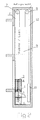
- (5) represents a spindle included by a nut (1).
- two rollers (2) are fixed for the purpose of loose deflection. They are moved up or down depending on the direction of rotation of the spindle.
- (4) represents a suspension to which one or more cables (11) are attached.
- a rope is shown. It can also be several ropes, for example, five ropes, which are led together over the roles. By the number of ropes and the weight of any existing counterweight or the strength of the rope, the carrying capacity of a lift to be connected to the drive unit can be optimized.
- (3) is a role which serves the fixed deflection.
- the rope is led upwards from the suspension (4) over the rollers and can be attached therefrom for the purpose of moving an elevator car as a load.
- the cable can be guided by appropriate deflection (not shown) to the load and can thus serve, for example, for up and down movement of a lift. If necessary, the rope can also be led directly to the load without deflection.
- the spindle is driven by a motor (6).
- the elevator which is moving upwards, may be provided with a device for the recovery of electricity, with recovery going downwards.
- the drive system according to the invention can be used in a variety of ways.
- the effort and cost of manufacturing are extremely low. All items are inexpensive to produce or commercially available at short notice.
- the assembly time is extremely low.
- the drive system can be used for new lifts and for the conversion of old systems, eg when replacing hydraulic drives. It is very environmentally friendly, since no hydraulic drive is required and the associated risk of oil leakage does not exist.
- the system is extremely space-saving due to the small space requirement and can be easily mounted in a pit, in the shaft itself, at the shaft head or outside the shaft. Frictional losses and wear can be practically neglected.
- the handling is very accurate, a drop in the floor does not take place. Also, installed in the shaft shaft copying can be omitted. The system is insensitive to temperature fluctuations and dirt. Power consumption is low, and when moving down, power can be recovered. Further advantages could be enumerated.
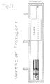
- the embodiment with counterweight is shown schematically and exemplified with reference to Fig. 2 ,
- the unit has a motor (6) or other means, whereby the spindle (5) is driven.
- it can have a device (not shown) with which the spindle can be moved by hand, for example.
- the driven rotating spindle acts on the nut (1) are attached to the two pulleys (2). These are used for loose deflection of the cable 11, which is further attached to a fixed suspension (4).
- the cable (11) extends from the fixed suspension (4) via the right deflection roller (2) to the fixed roller (3), which is located at the upper end of the spindle, then via the left roller (2) to the fixed guide roller (7).
- the counterweight (10) is movable up and down.
- the rope (12) extends from the counterweight over the fixed roller (8) to the load, generally a car. The counterweight thus acts on the load and thus reduces according to the translation, the force that is necessary to move the elevator.
- FIG. 3 an arrangement is shown in which the drive unit is located at the lower part of the shaft, preferably in a shaft pit.
- FIG. 4 an embodiment is shown in which the drive unit is mounted in the shaft head. It is also possible to mount the drive unit above the manhole cover and to guide the cable through an opening to the cabin.
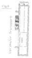
- FIG. 5 An arrangement of the drive unit is shown in the middle part of the shaft.
- FIG. 6 an arrangement outside the elevator shaft is shown.
- the rope is guided over two pulleys to the car.
- FIG. 7 An embodiment for moving loads horizontally is illustrated.
- heavy objects eg tree trunks, but also vehicles such as lorries can be pulled.
- FIG. 8 presented an embodiment for an oblique transport over inclined planes, eg an inclined elevator.
- the load can be influenced by selecting the ratio and the path length, the same applies to the speed at which the elevator can be moved.
- the drive unit can be arranged and transported in a housing and can also be used as an integral part of the housing in place.
Description
Die Erfindung betrifft eine Antriebseinheit, mit welcher Vorrichtungen zum Bewegen von Lasten und Personen wie z.B. Aufzüge ausgerüstet werden können und welche eine Spindel und Seile, Ketten oder Riemen aufweist und mit welcher eine mehrfache Übersetzung und höhere Geschwindigkeiten erreicht werden können. Die Erfindung betrifft ferner Vorrichtungen, insbesondere Aufzüge zum Transportieren von Lasten und Personen, welche mit derartigen Antriebseinheiten arbeiten.The invention relates to a drive unit with which devices for moving loads and persons such as e.g. Elevators can be equipped and which has a spindle and ropes, chains or belts and with which a multiple translation and higher speeds can be achieved. The invention further relates to devices, in particular elevators for transporting loads and persons who work with such drive units.
Antriebseinheiten, welche zum Bewegen von Lasten und Personen mit entsprechenden Vorrichtungen, insbesondere Aufzügen eingesetzt werden können, sind seit langem bekannt.Drive units which can be used for moving loads and persons with corresponding devices, in particular elevators, have long been known.
Dazu gehören beispielsweise die hydraulisch arbeitenden Systeme, wie sie beispielsweise in der deutschen Offenlegungsschrift
Hydraulisch betriebene Antriebseinheiten sind jedoch sehr sensibel und erfordern nicht nur eine häufige Überwachung und Wartung im Pumpenbereich sondern auch des Hydraulikzylindersystems. Auch muss das Hydrauliköl regelmäßig erneuert werden, was mit Kosten und Arbeitsaufwand verbunden ist. Auch muß während des Betriebs der Ölstand kontrolliert werden und auch Öl nachgefüllt werden. Öl ist im übrigen in seinen Eigenschaften sehr temperaturabhängig, nicht zu vergessen sind auch die Probleme des Umweltschutzes wie Gefahren der Verschmutzung der Umwelt und die behördlichen Sicherheitsauflagen.
Auch ist es sehr schlecht, dass sehr viel Hydrauliköl benötigt wird.However, hydraulically operated drive units are very sensitive and require not only frequent monitoring and maintenance in the pump area but also the hydraulic cylinder system. Also, the hydraulic oil must be renewed regularly, which is associated with costs and labor. Also, the oil level must be checked during operation and also oil refilled. Incidentally, oil is very temperature-dependent in terms of its properties, not to forget the problems of environmental protection such as environmental pollution hazards and regulatory safety requirements.
Also, it is very bad that a lot of hydraulic oil is needed.
Ein System, das ohne Hydraulik sondern mittels eines Flaschenzugsystems arbeitet, wird in der
In der deutschen Patentschrift
Mit dieser Anlage sind jedoch nur Bewegungen in vertikaler Richtung möglich. Diese Entwicklung bringt allerdings gegenüber den Aufzügen gemäß dem Stand der Technik schon beachtliche Vorteile.With this system, however, only movements in the vertical direction are possible. However, this development brings considerable advantages over the elevators according to the prior art.
In der
Obwohl bereits eine Reihe von Aufzügen mit verschieden Antrieben bekannt sind, besteht noch ein Bedürfnis nach Aufzügen insbesondere nach Antriebseinheiten, die einfacher aufgebaut sind, vielseitiger anwendbar sind und Vorteile gegenüber dem bekannten Stand der Technik bringen.Although a number of elevators with various drives are already known, there is still a need for elevators, in particular drive units, which are simpler, more versatile, and provide advantages over the prior art.
Aufgabe der Erfindung ist es nun, eine Weiterentwicklung, Verbesserung und auch Vereinfachung gegenüber dem bekannten Stand der Technik zu bringen und insbesondere ein Antriebssystem zur Verfügung zu stellen, mit dem nicht nur Lasten und Personen in vertikaler Richtung sondern auch in schräger oder horizontaler Richtung bewegt werden können.The object of the invention is now to bring a further development, improvement and also simplification compared to the known prior art and in particular to provide a drive system available, with which not only loads and people are moved in the vertical direction but also in an oblique or horizontal direction can.
Aufgabe der Erfindung ist es ferner, eine Antriebseinheit zum Bewegen von Lasten und Personen zur Verfügung zu stellen, die einfach und mit wenigen Mitteln herstellbar und vielseitig einsetzbar ist, mit der insbesondere in vorteilhafter Weise Systeme ausgerüstet werden können, die ein vertikales, horizontales und schräges Bewegen von Lasten und Personen erlaubt und mit dem große Lasten befördert werden können und die eine hohe Transportgeschwindigkeit ermöglicht und die im übrigen als kompakte Einheit ausgeführt ist, die als solche oder in einem Gehäuse untergebracht transportiert werden kann und an Ort und Stelle montiert und eingesetzt werden kann.The object of the invention is also to provide a drive unit for moving loads and persons available that can be produced easily and with few resources and versatile, can be equipped with the particular advantageously systems that a vertical, horizontal and oblique Moving loads and persons allowed and can be transported with the large loads and which allows a high transport speed and which is otherwise designed as a compact unit that can be transported as such or housed in a housing and mounted in place and used can.
Aufgabe der Erfindung ist es ebenfalls, eine vorteilhafte Transport- bzw. Beförderungseinheit insbesondere einen Aufzug zur Verfügung zu stellen, der mit solchen Antriebseinheiten ausgerüstet ist.The object of the invention is also to provide an advantageous transport or transport unit, in particular an elevator, which is equipped with such drive units.
Eine weitere Aufgabe der Erfindung ist es ein Transportsystem insbesondere einen Aufzug mit einer Antriebseinheit zur Verfügung zu stellen, die mit geringem Energieeinsatz betrieben werden kann.A further object of the invention is to provide a transport system, in particular an elevator with a drive unit, which can be operated with low energy input.
Diese Aufgabe wird gelöst durch eine Antriebseinheit, welche aufweist eine Motor (6) angetriebene Spindel (5), die auf eine Mutter (1) einwirkt, an der zwei oder mehrere Umlenkrollen, Zahnräder oder Riemenscheiben (2) befestigt sind zur losen Umlenkung, und eine oder mehrere Umlenkrollen, Zahnräder oder Riemenscheiben (3) zur festen Umlenkung und eine feste Aufhängung (4) für Seile, Ketten oder Riemen (11), und die Seile, Ketten oder Riemen (11) eine Übersetzung von N : 1 bilden und N = 4 + n ist, wobei n eine ganze Zahl von -2 bis + 8 einschließlich 0 ist und das Seil, die Kette oder der Riemen (11), ggf. über eine Umlenkung, direkt mit einem Transportsystem verbunden werden kann.This object is achieved by a drive unit, which has a motor (6) driven spindle (5) which acts on a nut (1), are attached to the two or more pulleys, gears or pulleys (2) for loose deflection, and one or more fixed deflection pulleys, gears or pulleys (3) and a fixed suspension (4) for ropes, chains or belts (11), and the cables, chains or belts (11) provide a ratio of N: 1 and N = 4 + n, where n is an integer from -2 to +8 inclusive 0 and the rope, chain or belt (11), possibly via a diverter, can be connected directly to a transport system.
Andere, auch noch größere, Übersetzungsverhältnisse sind möglich.Other, even larger, ratios are possible.
Vorzugsweise ist n = -2 bis 4, insbesondere 0.Preferably n = -2 to 4, in particular 0.
Die Spindel ist vorteilhaft als Kugelgewindespindel ausgeführt.The spindle is advantageously designed as a ball screw spindle.
Die Antriebseinheit kann vorteilhaft in einem Gehäuse angeordnet sein, das eine Öffnungsmöglichkeit zum Ausleiten und Verbinden des Seils mit einer Last aufweist.The drive unit may advantageously be arranged in a housing which has an opening possibility for discharging and connecting the cable to a load.
Ein weiterer Gegenstand der Erfindung ist eine Vorrichtung zum Bewegen, Heben oder Senken in vertikaler, horizontaler oder schräger Richtung von Lasten oder Personen, wobei die Vorrichtung zum Antrieb eine Antriebseinheit einer der vorstehend beschriebenen Art aufweist.Another object of the invention is an apparatus for moving, lifting or lowering in the vertical, horizontal or oblique direction of loads or persons, wherein the device for driving a drive unit of the type described above.
Vorzugweise ist die Vorrichtung ein Aufzug.Preferably, the device is an elevator.
Eine weitere vorteilhafte Ausführungsform der Erfindung ist ein Aufzug mit einer Antriebseinheit zum auf und abwärts Bewegen eines Personen- und/oder Lastenaufzuges, welche aufweist eine Motor (6) angetriebene Kugelrollspindel (5), die auf eine Mutter (1) einwirkt, an der zwei oder mehrere Umlenkrollen, Zahnräder oder Riemenscheiben (2) befestigt sind zur losen Umlenkung, und ein oder mehrere Umlenkrollen, Zahnräder oder Riemenscheiben (3) zur festen Umlenkung und eine feste Aufhängung (4) für Seile, Ketten oder Riemen (11), wobei die Seile, Ketten oder Riemen eine Übersetzung von N : 1 bilden und N = 4 + n ist und n eine ganze Zahl von - 2 bis + 8 einschließlich = 0, vorzugsweise -2 bis + 4 einschließlich = 0 ist und der Aufzug zwei weitere feste Umlenkrollen, Zahnräder oder Riemenscheiben (7, 8) aufweist und die Kabine/ Last (9) fahrbar mittels Seilen, Ketten oder Riemen über die Rollen, Zahnräder oder Riemenscheiben (7) und (8) angeordnet sind und das über Umlenkrolle, Zahnrad oder Riemenscheibe (8) geführte Seil bzw. Kette oder Riemen mit einem Gegengewicht (10) zur Kabine/Last (9) versehen ist.A further advantageous embodiment of the invention is an elevator with a drive unit for moving up and down a passenger and / or goods lift, which has a motor (6) driven ball screw (5) which acts on a nut (1), on the two or more pulleys, gears or pulleys (2) are mounted for loose deflection, and one or more pulleys, gears or pulleys (3) for fixed deflection and a fixed suspension (4) for ropes, chains or belts (11), wherein the Ropes, chains or belts form a ratio of N: 1 and N = 4 + n and n is an integer from -2 to +8 inclusive = 0, preferably -2 to +4 inclusive = 0 and the elevator is two more fixed ones Pulleys, gears or pulleys (7, 8) and the cabin / load (9) are arranged by means of ropes, chains or belts on the rollers, gears or pulleys (7) and (8) and the over pulley, Gear or pulley (8) guided rope or chain or belt with a counterweight (10) to the cabin / load (9) is provided.
Bevorzugt ist n = 0,die Masse des Gegengewichts ist vorteilhaft austauschbar.Preferably, n = 0, the mass of the counterweight is advantageously exchangeable.
Die Erfindung wird u.a. im Folgenden anhand der schematischen Zeichnungen näher erläutert. Es ist dargestellt in
- Fig. 1
- eine erfindungsgemäße in einem Gehäuse angeordnete Antriebseinheit
- Fig. 2
- eine Antriebseinheit mit Kabine und Gegengewicht
- Fig. 3
- eine Antriebseinheit untergebracht im unteren Teil eines Aufzugschachtes
- Fig. 4
- eine Antriebseinheit untergebracht im oberen Teil des Aufzugschachtes
- Fig. 5
- eine Antriebseinheit untergebracht im mittleren Teil des Schachtes
- Fig. 6
- eine Antriebseinheit angeordnet neben und außerhalb des Schachtes
- Fig. 7
- eine Anordnung zum horizontalen Transport
- Fig. 8
- eine Anordnung zum schrägen Transport
- Fig. 1
- an inventive arranged in a housing drive unit
- Fig. 2
- a drive unit with cabin and counterweight
- Fig. 3
- a drive unit housed in the lower part of a hoistway
- Fig. 4
- a drive unit housed in the upper part of the elevator shaft
- Fig. 5
- a drive unit housed in the middle part of the shaft
- Fig. 6
- a drive unit arranged beside and outside the shaft
- Fig. 7
- an arrangement for horizontal transport
- Fig. 8
- an arrangement for oblique transport
Durch die kompakte Bauweise ist die Bewegungsfreiheit des Aufzuges durch die ganze Schachtlänge gewährleistet, gleichgültig ob die Antriebseinheit am oberen oder unteren Teil des Schachtes oder an einer beliebigen Stelle innerhalb des Schachtes angebracht ist.Due to the compact design, the freedom of movement of the elevator through the entire length of the shaft is ensured, regardless of whether the drive unit is mounted on the upper or lower part of the shaft or at any point within the shaft.
An Hand der
Der nach oben bewegte Aufzug kann mit einer Vorrichtung zur Gewinnung von Strom versehen werden, wobei abwärts rückgewonnen wird.The elevator, which is moving upwards, may be provided with a device for the recovery of electricity, with recovery going downwards.
Das Antriebssystem gemäß der Erfindung kann auf die verschiedenste Weise eingesetzt werden.The drive system according to the invention can be used in a variety of ways.
Besonders geeignet ist es als Antriebssystem für Aufzugsanlagen. Der Aufwand und die Kosten für die Herstellung sind äußerst gering. Alle Einzelteile sind preiswert herstellbar bzw. im Handel kurzfristig erhältlich. Die Montagezeit ist äußerst gering. Das Antriebssystem kann bei Neubau von Aufzügen und beim Umbau von alten Anlagen z.B. bei Ersatz von hydraulischen Antrieben eingesetzt werden. Es ist sehr umweltfreundlich, da kein hydraulischer Antrieb erforderlich ist und die damit verbundene Gefahr von Ölaustritt nicht besteht. Das System ist äußerst Platz sparend auf Grund des geringen Raumbedarfs und kann ohne weiteres in einer Schachtgrube, im Schacht selbst, am Schachtkopf oder auch außerhalb des Schachtes montiert werden. Reibungsverluste und Verschleiß können praktisch vernachlässigt werden.It is particularly suitable as a drive system for elevator systems. The effort and cost of manufacturing are extremely low. All items are inexpensive to produce or commercially available at short notice. The assembly time is extremely low. The drive system can be used for new lifts and for the conversion of old systems, eg when replacing hydraulic drives. It is very environmentally friendly, since no hydraulic drive is required and the associated risk of oil leakage does not exist. The system is extremely space-saving due to the small space requirement and can be easily mounted in a pit, in the shaft itself, at the shaft head or outside the shaft. Frictional losses and wear can be practically neglected.
Das Fahrverhalten ist sehr genau, ein Absinken in der Etage findet nicht statt. Auch kann eine im Schacht installierte Schachtkopierung entfallen. Die Anlage ist unempfindlich gegenüber Temperaturschwankungen und Schmutzeinwirkungen. Der Stromverbrauch ist gering, und bei Abwärtsbewegung kann Strom rückgewonnen werden. Weitere Vorteile ließen sich aufzählen.The handling is very accurate, a drop in the floor does not take place. Also, installed in the shaft shaft copying can be omitted. The system is insensitive to temperature fluctuations and dirt. Power consumption is low, and when moving down, power can be recovered. Further advantages could be enumerated.
Die Ausführungsform mit Gegengewicht wird schematisch dargestellt und beispielhaft erläutert anhand von
In
In
In
In
In
Mit der Erfindung ist es möglich, den Energieverbrauch beim Fahren des Aufzugs zu verringern. Ferner kann die Last mittels Wahl der Übersetzung und die Weglänge beeinflusst werden, das Gleiche gilt auch für die Geschwindigkeit, mit welcher der Aufzug bewegt werden kann.With the invention it is possible to reduce the energy consumption when driving the elevator. Furthermore, the load can be influenced by selecting the ratio and the path length, the same applies to the speed at which the elevator can be moved.
Durch Anpassung der Masse des Gegengewichts kann man sich schnell auf das Gewicht der Kabine bzw. der Lasten, die regelmäßig bewegt werden sollen, einstellen.By adjusting the mass of the counterweight, you can quickly adjust to the weight of the cabin or loads that are to be moved regularly.
Infolge der kompakten Bauweise kann die Antriebseinheit in einem Gehäuse angeordnet und transportiert werden und kann auch als integraler Bestandteil mit dem Gehäuse an Ort und Stelle eingesetzt werden.As a result of the compact design, the drive unit can be arranged and transported in a housing and can also be used as an integral part of the housing in place.
Claims (9)
- A drive unit for moving loads and people comprising a motor (6) driven spindle (5) which acts on a nut (1) to which two or more deflection pulleys, gear wheels or belt pulleys (2) are attached for loose deflection, and one or more deflection pulleys, gear wheels or belt pulleys (3) for fixed deflection and a fixed suspension (4) for cables, chains or belts (11) wherein the cables, chains and belts form a gear ratio of N : 1, and N = 4 + n, whereby n is an integer from -2 to +8 inclusively 0 and the cable, chain or belt, optionally via a deflection, is configured for connection to a transport system.
- The drive unit according to claim 1, characterised in that n = - 2 to 4, in particular 0.
- The drive unit according to claim 1 or 2, characterised in that the spindle is a ball screw spindle.
- The drive unit according to at least one of the claims 1 to 3, characterised in that the drive unit is arranged in a housing, which has an opening for leading and connecting the cable with a load.
- A device for moving, raising or lowering loads or people in a vertical, horizontal or inclined direction, characterised in that the device has for driving a drive unit according to one more of the claims 1 to 4.
- A device according to claim 5, characterised in that the device is an elevator.
- An elevator comprising a linear drive unit according to claim 1 for moving a passenger elevator and or freight elevator up and down which comprises a motor (6) driven ball screw spindle (5) which acts on a nut (1) to which two or more deflection pulleys, gear wheels or belts pulleys(2) are attached for loose deflection, and one or more deflection pulleys, gear wheels or belt pulleys (3) for fixed deflection and a fixed suspension (4) for cables, chains or belts (11) whereby the cables, chains or belts have a gear ratio of N : 1 whereby N = 4 + n and n is an integer from -2 to + 8 inclusively 0, and the elevator comprises two further deflection pulleys, gear wheels or belt pulleys (7) and (8) and the car load (9) is drivably arranged by ways of cables, chains or belts (7) and (8) and the cable (12) which is guided over the deflecion pulley, gear wheel or belt pulley is provided with a counter weight (10) for the car load.
- Linear driving unit according to claim 6, characterized in that n = - 2 to 4 in particular 0.
- Linear driving unit according claim 6 or 7, characterized in that the mass of the counter weight is exchangeable.
Priority Applications (1)
| Application Number | Priority Date | Filing Date | Title |
|---|---|---|---|
| PL12721912T PL2702002T3 (en) | 2011-04-28 | 2012-04-12 | Drive unit for moving loads and people, and devices for moving people and loads comprising such drive units |
Applications Claiming Priority (4)
| Application Number | Priority Date | Filing Date | Title |
|---|---|---|---|
| DE201120005664 DE202011005664U1 (en) | 2011-04-28 | 2011-04-28 | 4: 1 linear drive unit |
| DE102011102199 | 2011-05-19 | ||
| DE201120108577 DE202011108577U1 (en) | 2011-12-03 | 2011-12-03 | 4: 1 linear drive unit with counterweight |
| PCT/IB2012/000736 WO2013050824A1 (en) | 2011-04-28 | 2012-04-12 | Drive unit for moving loads and people, and devices for moving people and loads comprising such drive units |
Publications (3)
| Publication Number | Publication Date |
|---|---|
| EP2702002A1 EP2702002A1 (en) | 2014-03-05 |
| EP2702002B1 true EP2702002B1 (en) | 2015-09-09 |
| EP2702002B8 EP2702002B8 (en) | 2015-12-02 |
Family
ID=46124561
Family Applications (1)
| Application Number | Title | Priority Date | Filing Date |
|---|---|---|---|
| EP12721912.9A Active EP2702002B8 (en) | 2011-04-28 | 2012-04-12 | Drive unit for moving loads and people, and devices for moving people and loads comprising such drive units |
Country Status (10)
| Country | Link |
|---|---|
| US (1) | US9624074B2 (en) |
| EP (1) | EP2702002B8 (en) |
| JP (1) | JP5947373B2 (en) |
| CN (2) | CN108373096A (en) |
| BR (1) | BR112013027552A2 (en) |
| DE (1) | DE102012007174A1 (en) |
| ES (1) | ES2549554T3 (en) |
| PL (1) | PL2702002T3 (en) |
| RU (1) | RU2013152736A (en) |
| WO (1) | WO2013050824A1 (en) |
Families Citing this family (7)
| Publication number | Priority date | Publication date | Assignee | Title |
|---|---|---|---|---|
| CN103863925A (en) * | 2014-03-06 | 2014-06-18 | 金湘江 | Lead-screw multiplying and lifting system |
| CN104003265B (en) * | 2014-06-18 | 2016-04-27 | 沈传良 | Reversely hung Yong side hydraulic pressure goods lift |
| US10054176B2 (en) * | 2015-02-25 | 2018-08-21 | Rock Exotica Llc | Lift systems, line brakes, and methods of vertically moving loads |
| US10173144B2 (en) * | 2016-10-19 | 2019-01-08 | James HEATH | Lift system with moving cam assembly and related methods |
| RU2708403C2 (en) * | 2017-12-12 | 2019-12-06 | Акционерное общество "Информационные спутниковые системы" имени академика М.Ф. Решетнёва" | Motion transmission mechanism |
| CN109533814A (en) * | 2018-11-27 | 2019-03-29 | 浙江德马科技股份有限公司 | Heavy-load reciprocating type vertical conveyor |
| CN113023525A (en) * | 2021-04-14 | 2021-06-25 | 四川孚朗吉建筑工程有限公司 | Compact home elevator |
Family Cites Families (16)
| Publication number | Priority date | Publication date | Assignee | Title |
|---|---|---|---|---|
| US2187390A (en) * | 1938-03-30 | 1940-01-16 | Reliance Elevator Mfg Company | Safety and indicating mechanism for elevators |
| CH615138A5 (en) | 1977-11-18 | 1980-01-15 | Julio Villars | Load elevator |
| CH666250A5 (en) * | 1985-01-31 | 1988-07-15 | Inventio Ag | Two-level goods or personnel lift - has counterweights to cabin corners via toothed belt and lead-screw motor drive |
| DE3621851A1 (en) | 1985-07-09 | 1987-01-29 | Thyssen Aufzuege Gmbh | HYDRAULIC ELEVATOR |
| JPS63106289A (en) * | 1986-10-22 | 1988-05-11 | 株式会社日立製作所 | Fluid pressure elevator |
| JPH0797164A (en) * | 1993-09-29 | 1995-04-11 | Mitsubishi Electric Corp | Brake device for linear motor elevator |
| IT1293687B1 (en) | 1997-08-08 | 1999-03-08 | Primafase S R L | ELEVATOR GROUP, PARTICULARLY FOR THE MOVEMENT OF PEOPLE. |
| DE29820101U1 (en) * | 1997-11-11 | 1999-04-08 | Becker Horst | Elevator with spindle hoist drive |
| JP2000038271A (en) * | 1998-07-23 | 2000-02-08 | Otis Elevator Co | Car self-running type elevator |
| JP2001063934A (en) * | 1999-08-27 | 2001-03-13 | Mitsubishi Electric Corp | Elevator device |
| JP4912526B2 (en) * | 2000-10-27 | 2012-04-11 | 日本エレベーター製造株式会社 | Screw weight for elevator |
| KR100752718B1 (en) * | 2006-01-17 | 2007-08-29 | 조병진 | Elevator of screw shaft type |
| FI119147B (en) * | 2007-05-25 | 2008-08-15 | Kone Corp | Arrangement for equalization of link forces in a drive pulley elevator |
| US20100126807A1 (en) | 2008-11-22 | 2010-05-27 | Tien-Tzu Liao | Screw elevator |
| EP2497739A1 (en) * | 2011-03-10 | 2012-09-12 | Hansruedi Diethelm | Lift |
| DE202011108577U1 (en) * | 2011-12-03 | 2012-06-12 | Horst Becker | 4: 1 linear drive unit with counterweight |
-
2012
- 2012-04-12 ES ES12721912.9T patent/ES2549554T3/en active Active
- 2012-04-12 US US14/114,451 patent/US9624074B2/en active Active
- 2012-04-12 WO PCT/IB2012/000736 patent/WO2013050824A1/en active Application Filing
- 2012-04-12 EP EP12721912.9A patent/EP2702002B8/en active Active
- 2012-04-12 BR BR112013027552A patent/BR112013027552A2/en not_active IP Right Cessation
- 2012-04-12 PL PL12721912T patent/PL2702002T3/en unknown
- 2012-04-12 DE DE102012007174A patent/DE102012007174A1/en not_active Ceased
- 2012-04-12 CN CN201810178522.9A patent/CN108373096A/en active Pending
- 2012-04-12 JP JP2014506943A patent/JP5947373B2/en active Active
- 2012-04-12 RU RU2013152736/11A patent/RU2013152736A/en not_active Application Discontinuation
- 2012-04-12 CN CN201280020746.8A patent/CN103517865A/en active Pending
Also Published As
| Publication number | Publication date |
|---|---|
| ES2549554T3 (en) | 2015-10-29 |
| PL2702002T3 (en) | 2016-05-31 |
| US20140054115A1 (en) | 2014-02-27 |
| CN103517865A (en) | 2014-01-15 |
| CN108373096A (en) | 2018-08-07 |
| EP2702002A1 (en) | 2014-03-05 |
| JP2014512319A (en) | 2014-05-22 |
| BR112013027552A2 (en) | 2017-01-10 |
| US9624074B2 (en) | 2017-04-18 |
| DE102012007174A1 (en) | 2012-10-31 |
| JP5947373B2 (en) | 2016-07-06 |
| RU2013152736A (en) | 2015-06-10 |
| WO2013050824A1 (en) | 2013-04-11 |
| EP2702002B8 (en) | 2015-12-02 |
Similar Documents
| Publication | Publication Date | Title |
|---|---|---|
| EP2702002B1 (en) | Drive unit for moving loads and people, and devices for moving people and loads comprising such drive units | |
| EP2426258B1 (en) | Conveyer and construction machine with a conveyer | |
| EP1184332B1 (en) | Lifting platform for vehicles | |
| DE112005003475T5 (en) | Elevator car with an angled beam stranding arrangement | |
| WO2014001883A1 (en) | Linear-motor drive unit for moving loads and people, and apparatuses for moving people and loads with such drive units | |
| DE19851726C2 (en) | Elevator with spindle hoist drive | |
| DE202011108577U1 (en) | 4: 1 linear drive unit with counterweight | |
| DE2056429A1 (en) | Movable device for reaching under and then lifting loads | |
| DE10200874A1 (en) | Lift for people and or freight has cage driven by drive unit with drive wheel, power transmission unit, chain with links and shaft | |
| AT510921B1 (en) | Device for transporting loads or persons | |
| DE102004019914B4 (en) | Multi-stage lifting system for a forklift | |
| DE19860703A1 (en) | Automatic transport/lifting system for loads in lorries etc. consists of parallel drive units and cradle with toothed gears, acting with drive units and engaging in open transport rail | |
| DE10154171A1 (en) | Hydraulic lift (elevator) modernizing process involves dismantling drive and cable, fitting counterweight with pulley and pulley drive unit, diverting pulley and fixing devices | |
| DE10319731A1 (en) | elevator | |
| DE202005009235U1 (en) | Cable swivel to unwind over-wound cable is integrated into cable run and has outline like that of cable roller, enabling it to pass over cable roller | |
| DE60025802T2 (en) | Truck or forklift with left and right pivoting or rotating load-bearing device | |
| DE202014000758U1 (en) | Mobile high seat | |
| EP2760778B1 (en) | Means of transport for loads or persons | |
| DE102013010455A1 (en) | RBG safety platform for the maintenance and service of stacker cranes (RBG) in high-bay warehouses | |
| EP0957060A1 (en) | Hydraulic rope lift | |
| AT413528B (en) | EMERGENCY EQUIPMENT FOR LIFTS | |
| DE2262063A1 (en) | LOAD ELEVATOR OR LADDER | |
| DE102011054928A1 (en) | Conveyor unit for use in material flow system for handling and/or conveying goods during e.g. storage of goods in free space, has support and/or conveyer surface rotatable around vertical or inclined axis | |
| DE4017304A1 (en) | Auxiliary equipment for loading goods vehicle - makes use of fork lift truck which can be mounted on loading surfaces | |
| WO2003072480A1 (en) | Vertical lift system with an automatically travelling chain drive |
Legal Events
| Date | Code | Title | Description |
|---|---|---|---|
| PUAI | Public reference made under article 153(3) epc to a published international application that has entered the european phase |
Free format text: ORIGINAL CODE: 0009012 |
|
| 17P | Request for examination filed |
Effective date: 20130916 |
|
| AK | Designated contracting states |
Kind code of ref document: A1 Designated state(s): AL AT BE BG CH CY CZ DE DK EE ES FI FR GB GR HR HU IE IS IT LI LT LU LV MC MK MT NL NO PL PT RO RS SE SI SK SM TR |
|
| DAX | Request for extension of the european patent (deleted) | ||
| RIC1 | Information provided on ipc code assigned before grant |
Ipc: B66B 9/02 20060101ALI20150129BHEP Ipc: B66B 11/04 20060101AFI20150129BHEP |
|
| GRAP | Despatch of communication of intention to grant a patent |
Free format text: ORIGINAL CODE: EPIDOSNIGR1 |
|
| INTG | Intention to grant announced |
Effective date: 20150409 |
|
| GRAS | Grant fee paid |
Free format text: ORIGINAL CODE: EPIDOSNIGR3 |
|
| GRAA | (expected) grant |
Free format text: ORIGINAL CODE: 0009210 |
|
| AK | Designated contracting states |
Kind code of ref document: B1 Designated state(s): AL AT BE BG CH CY CZ DE DK EE ES FI FR GB GR HR HU IE IS IT LI LT LU LV MC MK MT NL NO PL PT RO RS SE SI SK SM TR |
|
| REG | Reference to a national code |
Ref country code: GB Ref legal event code: FG4D Free format text: NOT ENGLISH |
|
| REG | Reference to a national code |
Ref country code: AT Ref legal event code: REF Ref document number: 747962 Country of ref document: AT Kind code of ref document: T Effective date: 20150915 Ref country code: CH Ref legal event code: EP |
|
| REG | Reference to a national code |
Ref country code: IE Ref legal event code: FG4D Free format text: LANGUAGE OF EP DOCUMENT: GERMAN |
|
| REG | Reference to a national code |
Ref country code: DE Ref legal event code: R096 Ref document number: 502012004437 Country of ref document: DE |
|
| REG | Reference to a national code |
Ref country code: ES Ref legal event code: FG2A Ref document number: 2549554 Country of ref document: ES Kind code of ref document: T3 Effective date: 20151029 |
|
| RAP2 | Party data changed (patent owner data changed or rights of a patent transferred) |
Owner name: SHS VERMARKTUNG UG (HAFTUNGSBESCHRAENKT) & CO. KG |
|
| REG | Reference to a national code |
Ref country code: SE Ref legal event code: TRGR |
|
| PG25 | Lapsed in a contracting state [announced via postgrant information from national office to epo] |
Ref country code: LT Free format text: LAPSE BECAUSE OF FAILURE TO SUBMIT A TRANSLATION OF THE DESCRIPTION OR TO PAY THE FEE WITHIN THE PRESCRIBED TIME-LIMIT Effective date: 20150909 Ref country code: FI Free format text: LAPSE BECAUSE OF FAILURE TO SUBMIT A TRANSLATION OF THE DESCRIPTION OR TO PAY THE FEE WITHIN THE PRESCRIBED TIME-LIMIT Effective date: 20150909 Ref country code: GR Free format text: LAPSE BECAUSE OF FAILURE TO SUBMIT A TRANSLATION OF THE DESCRIPTION OR TO PAY THE FEE WITHIN THE PRESCRIBED TIME-LIMIT Effective date: 20151210 Ref country code: LV Free format text: LAPSE BECAUSE OF FAILURE TO SUBMIT A TRANSLATION OF THE DESCRIPTION OR TO PAY THE FEE WITHIN THE PRESCRIBED TIME-LIMIT Effective date: 20150909 Ref country code: NO Free format text: LAPSE BECAUSE OF FAILURE TO SUBMIT A TRANSLATION OF THE DESCRIPTION OR TO PAY THE FEE WITHIN THE PRESCRIBED TIME-LIMIT Effective date: 20151209 |
|
| REG | Reference to a national code |
Ref country code: FR Ref legal event code: RM Effective date: 20160104 |
|
| REG | Reference to a national code |
Ref country code: LT Ref legal event code: MG4D |
|
| PG25 | Lapsed in a contracting state [announced via postgrant information from national office to epo] |
Ref country code: RS Free format text: LAPSE BECAUSE OF FAILURE TO SUBMIT A TRANSLATION OF THE DESCRIPTION OR TO PAY THE FEE WITHIN THE PRESCRIBED TIME-LIMIT Effective date: 20150909 Ref country code: HR Free format text: LAPSE BECAUSE OF FAILURE TO SUBMIT A TRANSLATION OF THE DESCRIPTION OR TO PAY THE FEE WITHIN THE PRESCRIBED TIME-LIMIT Effective date: 20150909 |
|
| REG | Reference to a national code |
Ref country code: NL Ref legal event code: FP |
|
| REG | Reference to a national code |
Ref country code: FR Ref legal event code: PLFP Year of fee payment: 5 |
|
| PG25 | Lapsed in a contracting state [announced via postgrant information from national office to epo] |
Ref country code: SK Free format text: LAPSE BECAUSE OF FAILURE TO SUBMIT A TRANSLATION OF THE DESCRIPTION OR TO PAY THE FEE WITHIN THE PRESCRIBED TIME-LIMIT Effective date: 20150909 Ref country code: EE Free format text: LAPSE BECAUSE OF FAILURE TO SUBMIT A TRANSLATION OF THE DESCRIPTION OR TO PAY THE FEE WITHIN THE PRESCRIBED TIME-LIMIT Effective date: 20150909 Ref country code: IS Free format text: LAPSE BECAUSE OF FAILURE TO SUBMIT A TRANSLATION OF THE DESCRIPTION OR TO PAY THE FEE WITHIN THE PRESCRIBED TIME-LIMIT Effective date: 20160109 |
|
| PG25 | Lapsed in a contracting state [announced via postgrant information from national office to epo] |
Ref country code: RO Free format text: LAPSE BECAUSE OF FAILURE TO SUBMIT A TRANSLATION OF THE DESCRIPTION OR TO PAY THE FEE WITHIN THE PRESCRIBED TIME-LIMIT Effective date: 20150909 Ref country code: PT Free format text: LAPSE BECAUSE OF FAILURE TO SUBMIT A TRANSLATION OF THE DESCRIPTION OR TO PAY THE FEE WITHIN THE PRESCRIBED TIME-LIMIT Effective date: 20160111 |
|
| REG | Reference to a national code |
Ref country code: DE Ref legal event code: R097 Ref document number: 502012004437 Country of ref document: DE |
|
| PLBE | No opposition filed within time limit |
Free format text: ORIGINAL CODE: 0009261 |
|
| STAA | Information on the status of an ep patent application or granted ep patent |
Free format text: STATUS: NO OPPOSITION FILED WITHIN TIME LIMIT |
|
| 26N | No opposition filed |
Effective date: 20160610 |
|
| PG25 | Lapsed in a contracting state [announced via postgrant information from national office to epo] |
Ref country code: DK Free format text: LAPSE BECAUSE OF FAILURE TO SUBMIT A TRANSLATION OF THE DESCRIPTION OR TO PAY THE FEE WITHIN THE PRESCRIBED TIME-LIMIT Effective date: 20150909 Ref country code: SI Free format text: LAPSE BECAUSE OF FAILURE TO SUBMIT A TRANSLATION OF THE DESCRIPTION OR TO PAY THE FEE WITHIN THE PRESCRIBED TIME-LIMIT Effective date: 20150909 |
|
| REG | Reference to a national code |
Ref country code: IE Ref legal event code: MM4A |
|
| REG | Reference to a national code |
Ref country code: FR Ref legal event code: PLFP Year of fee payment: 6 |
|
| PG25 | Lapsed in a contracting state [announced via postgrant information from national office to epo] |
Ref country code: IE Free format text: LAPSE BECAUSE OF NON-PAYMENT OF DUE FEES Effective date: 20160412 |
|
| REG | Reference to a national code |
Ref country code: FR Ref legal event code: PLFP Year of fee payment: 7 |
|
| PG25 | Lapsed in a contracting state [announced via postgrant information from national office to epo] |
Ref country code: HU Free format text: LAPSE BECAUSE OF FAILURE TO SUBMIT A TRANSLATION OF THE DESCRIPTION OR TO PAY THE FEE WITHIN THE PRESCRIBED TIME-LIMIT; INVALID AB INITIO Effective date: 20120412 Ref country code: SM Free format text: LAPSE BECAUSE OF FAILURE TO SUBMIT A TRANSLATION OF THE DESCRIPTION OR TO PAY THE FEE WITHIN THE PRESCRIBED TIME-LIMIT Effective date: 20150909 Ref country code: CY Free format text: LAPSE BECAUSE OF FAILURE TO SUBMIT A TRANSLATION OF THE DESCRIPTION OR TO PAY THE FEE WITHIN THE PRESCRIBED TIME-LIMIT Effective date: 20150909 |
|
| PG25 | Lapsed in a contracting state [announced via postgrant information from national office to epo] |
Ref country code: MK Free format text: LAPSE BECAUSE OF FAILURE TO SUBMIT A TRANSLATION OF THE DESCRIPTION OR TO PAY THE FEE WITHIN THE PRESCRIBED TIME-LIMIT Effective date: 20150909 Ref country code: MC Free format text: LAPSE BECAUSE OF FAILURE TO SUBMIT A TRANSLATION OF THE DESCRIPTION OR TO PAY THE FEE WITHIN THE PRESCRIBED TIME-LIMIT Effective date: 20150909 Ref country code: MT Free format text: LAPSE BECAUSE OF FAILURE TO SUBMIT A TRANSLATION OF THE DESCRIPTION OR TO PAY THE FEE WITHIN THE PRESCRIBED TIME-LIMIT Effective date: 20150909 |
|
| PG25 | Lapsed in a contracting state [announced via postgrant information from national office to epo] |
Ref country code: BG Free format text: LAPSE BECAUSE OF FAILURE TO SUBMIT A TRANSLATION OF THE DESCRIPTION OR TO PAY THE FEE WITHIN THE PRESCRIBED TIME-LIMIT Effective date: 20150909 |
|
| PG25 | Lapsed in a contracting state [announced via postgrant information from national office to epo] |
Ref country code: AL Free format text: LAPSE BECAUSE OF FAILURE TO SUBMIT A TRANSLATION OF THE DESCRIPTION OR TO PAY THE FEE WITHIN THE PRESCRIBED TIME-LIMIT Effective date: 20150909 |
|
| REG | Reference to a national code |
Ref country code: DE Ref legal event code: R082 Ref document number: 502012004437 Country of ref document: DE Representative=s name: OANDO OPPERMANN & OPPERMANN LLP, DE |
|
| PGFP | Annual fee paid to national office [announced via postgrant information from national office to epo] |
Ref country code: PL Payment date: 20230331 Year of fee payment: 12 |
|
| PGFP | Annual fee paid to national office [announced via postgrant information from national office to epo] |
Ref country code: NL Payment date: 20230417 Year of fee payment: 12 Ref country code: LU Payment date: 20230417 Year of fee payment: 12 |
|
| PGFP | Annual fee paid to national office [announced via postgrant information from national office to epo] |
Ref country code: IT Payment date: 20230428 Year of fee payment: 12 Ref country code: FR Payment date: 20230417 Year of fee payment: 12 Ref country code: ES Payment date: 20230517 Year of fee payment: 12 Ref country code: DE Payment date: 20230418 Year of fee payment: 12 Ref country code: CZ Payment date: 20230403 Year of fee payment: 12 Ref country code: CH Payment date: 20230502 Year of fee payment: 12 |
|
| PGFP | Annual fee paid to national office [announced via postgrant information from national office to epo] |
Ref country code: TR Payment date: 20230411 Year of fee payment: 12 Ref country code: SE Payment date: 20230419 Year of fee payment: 12 Ref country code: AT Payment date: 20230414 Year of fee payment: 12 |
|
| PGFP | Annual fee paid to national office [announced via postgrant information from national office to epo] |
Ref country code: BE Payment date: 20230417 Year of fee payment: 12 |
|
| PGFP | Annual fee paid to national office [announced via postgrant information from national office to epo] |
Ref country code: GB Payment date: 20230420 Year of fee payment: 12 |