EP2701023A2 - Motorsteuervorrichtung - Google Patents
Motorsteuervorrichtung Download PDFInfo
- Publication number
- EP2701023A2 EP2701023A2 EP13159315.4A EP13159315A EP2701023A2 EP 2701023 A2 EP2701023 A2 EP 2701023A2 EP 13159315 A EP13159315 A EP 13159315A EP 2701023 A2 EP2701023 A2 EP 2701023A2
- Authority
- EP
- European Patent Office
- Prior art keywords
- speed
- observer
- delay element
- order
- controlled object
- Prior art date
- Legal status (The legal status is an assumption and is not a legal conclusion. Google has not performed a legal analysis and makes no representation as to the accuracy of the status listed.)
- Withdrawn
Links
Images







Classifications
-
- G—PHYSICS
- G05—CONTROLLING; REGULATING
- G05B—CONTROL OR REGULATING SYSTEMS IN GENERAL; FUNCTIONAL ELEMENTS OF SUCH SYSTEMS; MONITORING OR TESTING ARRANGEMENTS FOR SUCH SYSTEMS OR ELEMENTS
- G05B11/00—Automatic controllers
- G05B11/01—Automatic controllers electric
- G05B11/36—Automatic controllers electric with provision for obtaining particular characteristics, e.g. proportional, integral, differential
- G05B11/42—Automatic controllers electric with provision for obtaining particular characteristics, e.g. proportional, integral, differential for obtaining a characteristic which is both proportional and time-dependent, e.g. P. I., P. I. D.
-
- G—PHYSICS
- G05—CONTROLLING; REGULATING
- G05B—CONTROL OR REGULATING SYSTEMS IN GENERAL; FUNCTIONAL ELEMENTS OF SUCH SYSTEMS; MONITORING OR TESTING ARRANGEMENTS FOR SUCH SYSTEMS OR ELEMENTS
- G05B19/00—Program-control systems
- G05B19/02—Program-control systems electric
- G05B19/18—Numerical control [NC], i.e. automatically operating machines, in particular machine tools, e.g. in a manufacturing environment, so as to execute positioning, movement or co-ordinated operations by means of program data in numerical form
- G05B19/416—Numerical control [NC], i.e. automatically operating machines, in particular machine tools, e.g. in a manufacturing environment, so as to execute positioning, movement or co-ordinated operations by means of program data in numerical form characterised by control of velocity, acceleration or deceleration
Definitions
- Each of Japanese Patent No. 3856215 and Japanese Patent Application Laid-open No. 2008-299573 discloses, for example, a configuration to make it possible to increase a control gain of a speed control loop in a motor control device by compensating a phase delay of a vibrational component in the speed control loop using a phase compensating speed observer.
- the phase compensating speed observer is provided, on the front stage side, with an equivalent rigid body model that assumes a controlled object as a rigid body, and, on the rear stage side, with a delay element model simulating a delay element that exists in a controller at a stage later than a PI controller or that exists in the controlled object.
- the equivalent rigid body model and the delay element model are connected in series to each other.
- the phase compensating speed observer supplies an output of the PI controller to the equivalent rigid body model, and also feeds back a signal obtained by subtracting an output of the delay element from a speed of the controlled object to an integral element through multiplication by a stabilizing gain. Then, the phase compensating speed observer outputs, as a speed feedback signal of the speed control loop, an input entered into the delay element model.
- the phase compensating speed observer disclosed in Japanese Patent No. 3856215 mentioned above is provided with a delay element model including only one integral element (1/s), that is, a first-order delay element model whose order is one.
- the phase compensating speed observer disclosed in Japanese Patent Application Laid-open No. 2008-299573 mentioned above is provided with a fourth-order delay element model in which the order of the integral element (1/s) is estimated to be high by exactly simulating the delay element existing in the controlled object.
- An object of an aspect of the embodiments is to provide a motor control device that compensates the phase delay in a wider frequency range as far as actually achievable so as to improve the performance of setting the control gain, and thereby that achieves more accurate follow-up performance of the controlled object speed against the speed reference.
- a motor control device includes a first subtractor, a speed controller, and a phase compensating speed observer.
- the first subtractor subtracts a speed reference from a speed feedback signal to obtain a speed deviation.
- the speed controller receives the speed deviation and outputs a first torque reference.
- the phase compensating speed observer receives the first torque reference and a speed of a controlled object including a motor, and outputs the speed feedback signal.
- the phase compensating speed observer includes a delay element model having an integral element of an order optimally satisfying a setting condition based on a degree of easiness for implementation and a degree of usefulness for phase delay compensation of the speed feedback signal to the speed reference.
- FIG. 1 is a block diagram illustrating a system configuration of an entire motor control device according to an embodiment
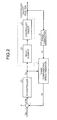
- FIG. 2 is a block diagram of a speed control system loop that is substituted from the viewpoint of a phase control
- FIG. 3 is a detailed block diagram of a phase compensating speed observer
- FIG. 4 is a block diagram of a simplified speed control system loop
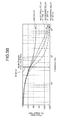
- FIGS. 5A and 5B are Bode diagrams of results obtained by simulating the simplified speed control system loop
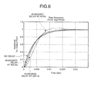
- FIG. 6 is a step response diagram of the results obtained by simulating the simplified speed control system loop
- FIGS. 7A to 7C are diagrams illustrating, by order, evaluation values of a degree of usefulness in phase compensation and of a degree of easiness of implementation, and a total of the evaluation values;
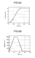
- FIGS. 8A to 8D are diagrams illustrating step response data when the motor control device is provided with PI control and the phase compensating speed observer implemented by a second-order delay element model of the embodiment;
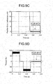
- FIGS. 9A to 9D are diagrams illustrating step response data when the motor control device is provided with the PI control and a phase compensating speed observer implemented by a conventional first-order delay element model;
- FIGS. 10A to 10D are diagrams illustrating step response data when the motor control device is provided with only the PI control but without the phase compensating speed observer;
- FIG. 11 is a block diagram a block diagram illustrating a system configuration of an entire motor control device when the motor control device is provided with an adjustment-free function;
- FIGS. 12A to 12C are diagrams illustrating step response data when the motor control device is provided with only the PI control but without the phase compensating speed observer, with the adjustment-free function disabled;
- FIGS. 13A to 13C are diagrams illustrating step response data when the motor control device is provided with only the PI control but without the phase compensating speed observer, with the adjustment-free function enabled;
- FIGS. 14A to 14C are diagrams illustrating step response data when the motor control device is provided with the PI control and the phase compensating speed observer implemented by a second-order delay element model of a modification, with the adjustment-free function enabled.
- the motor control device 100 controls a rotational position Pa (rotation angle) of a motor M based on a position reference ⁇ a supplied from a higher-level control device (not illustrated). Note that figures and explanations given below will be described all in the form of transfer functions.
- the motor control device 100 of the present embodiment includes a position controller 1, a speed controller 2, a first-order low-pass filter (first-order LPF) 3, a current controller 4, a speed converter 6, and a phase compensating speed observer 7.
- a position error ⁇ a is obtained as a difference between the supplied position reference ⁇ a and the rotational position Pa of the motor M detected by an encoder 5 (to be described later). Based on the position error ⁇ a, the position controller 1 outputs a speed reference Va so as to reduce the position error ⁇ a.
- a speed deviation ⁇ Va is obtained as a difference between the speed reference Va from the position controller 1 and an observer-estimated speed Vb compensated in phase by the phase compensating speed observer 7 (to be described later). Based on the speed deviation ⁇ Va, the speed controller 2 outputs a torque reference Ta so as to reduce the speed deviation ⁇ Va. Note that the speed deviation ⁇ Va is output from a subtractor 9.
- the first-order LPF 3 is composed of, for example, a first-order delay element provided therein with one integral element (1/s), which is not particularly illustrated.
- the first-order LPF 3 removes the high-frequency band component from the torque reference Ta supplied from the speed controller 2, and thus extracts and outputs only the low-frequency band component. With this operation, the first-order LPF 3 functions as a torque reference filter that suppresses vibration generated at a sampling frequency of the torque reference Ta.
- the current controller 4 Based on the torque reference Tb from the first-order LPF 3, the current controller 4 outputs a drive current, for example, by pulse-width modulation (PWM) control to the motor M.
- PWM pulse-width modulation
- the motor M generates torque from the drive current supplied from the current controller 4, and thereby drives a load machine (not illustrated).
- the encoder 5 is composed of, for example, a rotary encoder that is mechanically connected to a rotor of the motor M.
- the encoder 5 detects the rotational position Pa of the motor M.
- the speed converter 6 converts a change in the rotational position Pa of the motor M detected by the encoder 5 into a motor speed Vc of the motor M.
- a differentiator (s) can be sufficiently used as the speed converter 6.
- the phase compensating speed observer 7 outputs, based on the torque reference Ta output by the speed controller 2 and on the motor speed Vc of the motor M output by the speed converter 6, the observer-estimated speed Vb, which is compensated in phase so as to be advanced in phase relative to the motor speed Vc.
- a configuration of the phase compensating speed observer 7 will be described later in detail.
- the motor control device 100 configured as described above includes a triple loop configuration composed of a feedback loop of a position control system, a feedback loop of a speed control system, and a feedback loop of a current control system.
- the position control system loop In the feedback loop of the position control system (hereinafter called the position control system loop), after the position reference ⁇ a is supplied from the higher-level control device (not illustrated), the control signal and the detection signal are transmitted through the position controller 1, the speed controller 2, the first-order LPF 3, the current controller 4, the motor M, and the encoder 5 in this order, and the feedback is performed thereafter.
- the control signal and the detection signal are transmitted through the speed controller 2, the first-order LPF 3, the current controller 4, the motor M, and the encoder 5, the peed converter 6, and the phase compensating speed observer 7 in this order, and the feedback is performed thereafter.
- the speed controller 2 the first-order LPF 3
- the current controller 4 the motor M
- the encoder 5 the peed converter 6, and the phase compensating speed observer 7 in this order
- the feedback is performed thereafter.
- the phase compensating speed observer 7 compensates a phase delay in the speed feedback signal (motor speed) caused by unignorable influences from fluctuations in characteristic parameters of the motor M (such as a resistance of a motor coil, an inductance of the motor coil, and a motor's moment of inertia), or by a dead time caused by a digital servo. This compensation ensures robustness of response characteristics of the motor M.
- characteristic parameters of the motor M such as a resistance of a motor coil, an inductance of the motor coil, and a motor's moment of inertia
- the speed control system loop includes a PI controller 21, a delay element 22, a controlled object 23, the speed converter 6, and the phase compensating speed observer 7.
- the PI controller 21 corresponds to a functional element of the speed controller 2 in FIG. 1 .
- the PI controller 21 performs what is called a PI operation, in which a proportional operation (P operation) and an integrating operation (I operation) are performed in parallel on the speed deviation ⁇ Va, and outputs the torque reference Ta.
- P operation proportional operation
- I operation integrating operation
- a gain in the proportional operation among these operations corresponds to a speed loop gain (not particularly illustrated).
- the delay element 22 corresponds to delay elements included in the first-order LPF 3 and the current controller 4 in FIG. 1 .
- the delay element 22 is an element that generates a delay, relative to a change in the torque reference Ta supplied thereto, in a speed value converted from an output response of the subsequent controlled object, that is, in a response of the motor speed Vc in this example.
- the controlled object 23 corresponds to functional elements of the motor M in FIG. 1 and the load machine connected to the motor M.
- the controlled object 23 has a known inertia moment ratio between the rotor of the motor M and the load machine.
- the controlled object speed (motor speed) is the speed value converted from the output (motor position) of the controlled object, and is a delayed response to a change in the speed reference Va supplied to the speed control system loop. If the controlled object speed is directly fed back, the entire speed control system loop is likely to oscillate. Particularly when the speed loop gain is set to a large value, the entire speed control system loop easily oscillates because the high-frequency component in the torque reference Ta significantly delays in phase.
- the phase compensating speed observer 7 outputs, as the observer-estimated speed Vb, an assumed controlled object speed that is estimated to be output if the controlled object speed responds without a delay to a change in the torque reference Ta supplied to the controller and the controlled object.
- the phase compensating speed observer 7 refers to the actual change in the torque reference Ta and outputs an observer-estimated speed Vb that is obtained by appropriately advancing the phase of the actually detected controlled object speed. Feeding back the observer-estimated speed Vb can prevent the oscillation in the speed control system loop.
- FIG. 3 illustrates a detailed block diagram of the phase compensating speed observer 7 in the present embodiment.
- the phase compensating speed observer 7 mainly includes an equivalent rigid body model 31, a delay element model 32, and an observer compensator 33.
- the equivalent rigid body model 31 is a model (mathematical model expressed by a transfer function) that assumes the controlled object (load machine) in FIG. 2 as the simplest rigid body.
- the delay element model 32 is a model (mathematical model expressed by a transfer function) that simulates the delay element 22 in FIG. 2 .
- the equivalent rigid body model 31 to which the torque reference Ta is supplied from the PI controller 21 is arranged on the front stage side while the delay element model 32 is arranged on the rear stage side, and the equivalent rigid body model 31 is connected in series to the delay element model 32.
- the delay element model 32 can be assumed to produce an output that simulates the actual controlled object speed and that has a small delay in phase.
- the phase compensating speed observer 7 uses the observer compensator 33 to appropriately compensate an error between the output of the delay element model 32 and the actual controlled object speed.
- the phase compensating speed observer 7 also feeds back and circulates the error compensated by the observer compensator 33 to the torque reference Ta supplied to the equivalent rigid body model 31.
- the output of the delay element model 32 can be further approximated to the actual controlled object speed.
- the equivalent rigid body model 31 can be regarded to be producing an output approximate to the controlled object speed from which the phase delay has been eliminated.
- the phase compensating speed observer 7 outputs this output as the observer-estimated speed having a phase ahead of that of the actual controlled object speed. Note that the above-described error is output from a subtractor 10.
- the equivalent rigid body model 31 and the delay element model 32 are provided with integral elements (1/s).
- the observer compensator 33 is configured to multiply the error by the observer stabilizing gains corresponding to each of the integral elements, and then to distribute the products to the input of each of the integral elements.
- the delay element model 32 is desirable to exactly simulate the delay element 22 including the delay elements existing in the first-order LPF 3 and the current controller 4, and further in the controlled object 23 including the motor M. Even in view of only the delay element, in addition to an order of the integral element provided in the first-order LPF 3, an order of the integral element inherent in the current controller 4 needs to be added to the order of the delay element model 32. Thus, the delay element model 32 needs to have a first or higher order. However, each time the total number of the integral elements to be integrated, that is, the order of the integral elements per processing signal is raised by one, it becomes more and more difficult to implement the delay element model 32 as a digital circuit or software.
- the order of the delay element model 32 has been set based on the following consideration.
- the speed control system loop illustrated in FIG. 2 is replaced with the most simplified model such as the one illustrated in FIG. 4 .
- This model multiplies the speed reference Va supplied thereto by a control gain 41 and a delay element 42 and a controlled object 43, and simply feeds back the output of the multiplication (speed).
- the control gain 41 is denoted as K; the delay element 42 as a first-order delay element 1/(1 + Ts); and the controlled object 43 as 1/s.
- FIGS. 5A , 5B , and 6 illustrate results of the simulations.
- FIGS. 5A and 5B are Bode diagrams (gain characteristics in FIG. 5A and phase characteristics in FIG. 5B ) of the above-mentioned results.
- the order of the integral elements in the delay element 22 should also be accurately estimated in order to make the delay element model 32 exactly simulate the delay element 22 including the delay elements existing in the first-order LPF 3 and the current controller 4, and further in the controlled object including the motor M.
- the inventor of the present application has newly found that raising the order of the delay element model 32 to a predetermined value or more hardly improves a degree of usefulness in the phase delay compensation.
- the degree of usefulness of the order of the integral elements in the phase compensation is defined as the influence of the order evaluated from the functional viewpoint of the phase delay compensation as described above.
- FIG. 7A is a diagram illustrating, as a distribution against the order, evaluation values of the degree of usefulness in the delay element model 32 illustrated in FIG. 3 .
- the degree of usefulness always monotonically increases as the order rises, the rate of change of the increase is only small when the order is three or higher, and the degree of usefulness converges into a nearly constant value.
- FIG. 7B is a diagram illustrating, as a distribution against the order, evaluation values of the degree of easiness of implementation in the delay element model 32 illustrated in FIG. 3 .
- the degree of easiness of implementation monotonically decreases substantially inversely proportionally to the rise in the order.
- FIGS. 7A and 7B illustrate the evaluation values in the same scale.
- the delay element model 32 be provided with the integral elements of an order satisfying the condition: the sum of the two evaluation values of the degree of usefulness in the phase compensation and the degree of easiness of the implementation is equal to or greater than a predetermined value.
- the delay element model 32 is provided with the integral elements of an order at which the sum is equal to or greater than the predetermined value in the distribution of FIG. 7C obtained by summing the distribution of FIG. 7A and the distribution of FIG. 7B .
- the sum of the two evaluation values is the highest at the second order.
- the delay element model 32 is provided with two integral elements, and the entire phase compensating speed observer 7 is of a fourth order (refer to FIG. 3 ). Note that the entire phase compensating speed observer 7 is a fourth-order system because a path for disturbance compensation has one integral element as will be described later.
- the observer compensator 33 distributes signals (refer to D, E, and F in FIG. 3 ) to inputs of the single integral element provided in the equivalent rigid body model 31 and of the two integral elements provided in the delay element model 32.
- These signals are signals obtained by multiplying the error between the output of the delay element model 32 and the actual controlled object speed (motor speed) by appropriate observer stabilizing gains.
- the observer compensator 33 adds, separately from the above-described distributed signals, a signal (refer to C in FIG. 3 ) obtained by multiplying the error by an integral element and an observer stabilizing gain to the input of the integral element of the equivalent rigid body model 31.
- This path is a path for disturbance compensation that takes into account an amount of shift due to disturbances caused by friction elements and the like in the load machine of the controlled object 23.
- the observer compensator 33 outputs through a total of four paths via the observer stabilizing gains.
- the effectiveness of the motor control device 100 of the present embodiment will be illustrated below with reference to specific step response data of FIGS. 8A to 10D .
- the axis label "Position" in each of FIGS. 8A , 9A , and 10A represents the position reference supplied from the higher-level control device (not illustrated) and the motor rotational position supplied from the encoder 5 (the same applies to all of FIGS. 12A , 13A , and 14A ). Note that, in any of FIGS. 8A , 9A , and 10A , the position reference and the motor rotational position are illustrated to almost coincide with each other because the motor rotational position responds well to the position reference.
- FIGS. 8B , 9B , and 10B represents the speed reference supplied to the speed control system loop and the motor speed (the same applies to all of FIGS. 12B , 13B , and 14B ).
- the axis label "Position Error” in each of FIGS. 8C , 9C , and 10C represents the position error A8a, which is the difference between the position reference and the motor rotational position supplied from the encoder 5 and is a signal directly supplied to the position controller 1 (the same applies to all of FIGS. 12C , 13C , and 14C ).
- the axis label "Torque” in each of FIGS. 8D , 9D , and 10D represents a torque reference Tb immediately before being supplied to the current controller 4.
- FIGS. 10C and 10D For a case in which the motor control device is provided with only the PI control but without the phase compensating speed observer 7, and in FIGS. 9C and 9D for a case in which the motor control device is provided with the PI control and a phase compensating speed observer implemented by a conventional first-order delay element model.
- FIGS. 9C and 9D it has been found that the suppression effect of the vibration when the motor is stopping is improved (refer to portions in ellipses drawn by dashed lines), in FIGS.
- the torque reference Ta output by the speed controller 2 corresponds to a first torque reference described in claims
- the equivalent rigid body model 31 corresponds to a controlled object model described in claims.
- the whole of the series-connected combination of the equivalent rigid body model 31 and the delay element model 32 corresponds to an observer object described in claims.
- the subtractor 9 corresponds to a first subtractor described in claims
- the subtractor 10 corresponds to a second subtractor described in claims.
- the delay element model 32 is configured to be provided with integral elements of an order optimally satisfying the setting condition based on the degree of usefulness in the phase delay compensation and the degree of easiness of implementation.
- the phase compensating speed observer 7 with an optimal balance can be achieved in consideration of the trade-off between the performance of the phase delay compensation and the feasibility in software implementation.
- the equivalent rigid body model 31 which receives the torque reference Ta output from the speed controller 2, is arranged on the front stage side, while the delay element model 32, which is obtained by modeling the delay elements existing in the control system including the controlled object 23, is arranged on the rear stage side, and the equivalent rigid body model 31 is connected in a series to the delay element model 32.
- the delay element model 32 can be assumed to produce an output that simulates the actual speed of the controlled object 23 and that has a small delay in phase.
- the phase compensating speed observer 7 multiplies the error between the output of the delay element model 32 and the actual speed of the controlled object 23 by the observer stabilizing gains of the observer compensator 33 to compensate the error, and thereafter, adds the products to the equivalent rigid body model 31 and the delay element model 32 to circulate the error.
- the output of the delay element model 32 can be further approximated to the actual speed of the controlled object.
- the equivalent rigid body model 31 can be regarded to be producing an output approximate to the speed of the controlled object from which the delay elements have been eliminated.
- the order that optimally satisfies the setting condition is set to be an order at which the sum of the evaluation values of the degree of usefulness in the phase delay compensation and the degree of easiness of implementation is largest.
- the optimal order can be set that takes into account both the degree of usefulness in the phase delay compensation and the degree of easiness of implementation.
- the setting condition is optimally satisfied when the order is two.
- the second-order delay element model 32 having the two integral elements is particularly the most suitable.
- the observer compensator 33 adds the first output C to the output of the PI controller 21.
- the phase compensating speed observer 7 has therein four integral elements including one integral element in the equivalent rigid body model 31 and one integral element in the path for disturbance compensation.
- the observer compensator 33 adds, to the inputs of the integral elements, the second output D, the third output E, and the fourth output F, which are multiplied by the respective stabilizing gains, thereby making it possible to stabilize the phase compensating speed observer 7.
- the above-described embodiment describes the case in which the fourth-order phase compensating speed observer 7 (second-order with only the delay element model 32) is applied to the motor control device 100 that does not compensate the load moment of inertia using a disturbance observer. In other cases, a favorable effect is also obtained by applying the fourth-order phase compensating speed observer 7 to a motor control device that compensates the load moment of inertia by using a disturbance observer.
- a motor control device 100A of the present modification further includes an inertia moment compensator 51, in addition to the configuration illustrated in FIG. 1
- the inertia moment compensator 51 calculates an estimated value of disturbance torque based on the rotational speed Vc of the motor M output by the speed converter 6 using the internal disturbance observer and on the torque reference that is output from the first-order LPF 3 and is about to be supplied to the current controller 4.
- the estimated value of disturbance torque is added, as an estimated disturbance torque Tc, at an adder 14 to the torque reference immediately after being output from the first-order LPF 3.
- the inertia moment compensator 51 adjusts the torque reference so as to reduce the influence of disturbances given to the rotor of the motor M.
- the robustness in the response characteristics of the motor M can be ensured even if an inertia moment ratio J 0 of the load machine is unknown or fluctuates.
- the inertia moment compensator 51 uses the disturbance observer to compensate the load moment of inertia of the motor M, thereby approximating the control system to a nominal model.
- the moment of inertia moment ratio J 0 increases, the moment of inertia cannot be compensated completely.
- An uncompensated portion of the moment of inertia can be regarded to act as a delay element from the viewpoint of the control system. This delay element breaks down the gain balance between the speed control system loop and the position control system loop, so that the entire motor control device 100A becomes likely to oscillate.
- the delay element model 32 is configured to be provided with integral elements of an order optimally satisfying the setting condition based on the degree of usefulness in the phase delay compensation and the degree of easiness of implementation.
- the phase compensating speed observer 7 with an optimal balance can be achieved in consideration of the performance of the phase delay compensation and the feasibility in software implementation.
- the phase compensating speed observer 7 configured in this manner can compensate a delay element equivalent to the portion of the moment of inertia that cannot be compensated by the inertia moment compensator 51, and thus can further stabilize the control system.
- phase compensating speed observer 7 when the phase compensating speed observer 7 is applied to the motor control device 100A that compensates the load moment of inertia by using the above-described disturbance observer, the phase compensating speed observer 7 can functionally complement the compensation of the load moment of inertia by the disturbance observer, and thus is useful.
- FIGS. 12A to 14C The effectiveness of the motor control device 100A of the present modification will be illustrated below with reference to specific step response data of FIGS. 12A to 14C .
- FIG. 12C illustrates the position error when the motor control device is provided with only the PI control but without the phase compensating speed observer 7.
- FIG. 13C illustrates the position error when the motor control device has the inertia moment compensator 51 and is provided with only the PI control but without the phase compensating speed observer 7.
- the position error in FIG. 13C is slightly delayed in phase relative to the position error in FIG. 12C (refer to portions in ellipses drawn by dashed lines). This means that a portion of the moment of inertia that was not be compensated as described above acted as a delay element from the viewpoint of the control system. Compared with this, FIG.
- FIG. 14C illustrates the position error when the motor control device has the inertia moment compensator 51 and is provided with the PI control and the phase compensating speed observer 7 implemented by the second-order delay element model 32 of the present modification.
- This position error in FIG. 14C maintains nearly the same phase as in the case of FIG. 12C (refer to portions in ellipses drawn by dashed lines). This result has proven that the suppression effect of the phase delay is improved.
Landscapes
- Engineering & Computer Science (AREA)
- Physics & Mathematics (AREA)
- General Physics & Mathematics (AREA)
- Automation & Control Theory (AREA)
- Human Computer Interaction (AREA)
- Manufacturing & Machinery (AREA)
- Control Of Electric Motors In General (AREA)
- Feedback Control In General (AREA)
Applications Claiming Priority (1)
| Application Number | Priority Date | Filing Date | Title |
|---|---|---|---|
| JP2012185923A JP5582425B2 (ja) | 2012-08-24 | 2012-08-24 | モータ制御装置 |
Publications (1)
| Publication Number | Publication Date |
|---|---|
| EP2701023A2 true EP2701023A2 (de) | 2014-02-26 |
Family
ID=47884187
Family Applications (1)
| Application Number | Title | Priority Date | Filing Date |
|---|---|---|---|
| EP13159315.4A Withdrawn EP2701023A2 (de) | 2012-08-24 | 2013-03-15 | Motorsteuervorrichtung |
Country Status (5)
| Country | Link |
|---|---|
| US (1) | US9285782B2 (de) |
| EP (1) | EP2701023A2 (de) |
| JP (1) | JP5582425B2 (de) |
| CN (1) | CN103633914B (de) |
| BR (1) | BR102013004985A2 (de) |
Cited By (1)
| Publication number | Priority date | Publication date | Assignee | Title |
|---|---|---|---|---|
| CN104849488A (zh) * | 2015-05-28 | 2015-08-19 | 南车株洲电力机车研究所有限公司 | 一种直线感应电机的速度监测方法 |
Families Citing this family (12)
| Publication number | Priority date | Publication date | Assignee | Title |
|---|---|---|---|---|
| JPWO2014010020A1 (ja) * | 2012-07-09 | 2016-06-20 | 株式会社安川電機 | モータ制御装置及びモータシステム |
| JP6931980B2 (ja) * | 2015-08-20 | 2021-09-08 | 三菱電機株式会社 | サーボ制御装置 |
| JP6623987B2 (ja) * | 2016-09-09 | 2019-12-25 | 株式会社デンソー | シフトレンジ制御装置 |
| JP7050624B2 (ja) * | 2018-08-24 | 2022-04-08 | 日立Astemo株式会社 | モータ制御装置及びこれを備えた電動ブレーキ装置 |
| CN109546922B (zh) * | 2018-12-05 | 2022-07-26 | 北京爱其科技有限公司 | 伺服电机控制方法和系统 |
| JP7116930B2 (ja) * | 2019-01-31 | 2022-08-12 | 株式会社安川電機 | モータ制御システム、エンコーダ、サーボモータ |
| JP7021147B2 (ja) * | 2019-04-03 | 2022-02-16 | ファナック株式会社 | モータ制御装置及びモータ制御用コンピュータプログラム |
| CN110018634B (zh) * | 2019-04-28 | 2021-11-16 | 北京控制工程研究所 | 一种提升控制力矩陀螺带宽的自适应框架控制系统及方法 |
| CN113114073B (zh) * | 2021-05-06 | 2023-06-20 | 中铁工程装备集团有限公司 | 盾构机的刀盘电机驱动控制方法及装置 |
| CN113311755B (zh) * | 2021-05-26 | 2022-05-10 | 广东电网有限责任公司 | 一种高频噪声幅值增益的自动跟踪改进方法及系统 |
| WO2023050226A1 (zh) * | 2021-09-29 | 2023-04-06 | 西门子股份公司 | 运动控制方法及装置 |
| CN114019874B (zh) * | 2021-11-05 | 2022-10-11 | 哈尔滨明快机电科技有限公司 | 一种基于dsp的液压马达控制装置及方法 |
Family Cites Families (5)
| Publication number | Priority date | Publication date | Assignee | Title |
|---|---|---|---|---|
| JP3804060B2 (ja) * | 2000-12-14 | 2006-08-02 | 株式会社安川電機 | フィードバック制御装置 |
| JP4411796B2 (ja) * | 2001-04-27 | 2010-02-10 | 富士電機システムズ株式会社 | 速度センサを持たない誘導モータドライブの制御システム、オブザーバ及び制御方法 |
| JP3856215B2 (ja) | 2002-03-19 | 2006-12-13 | 株式会社安川電機 | 速度制御装置 |
| DE112005000681B4 (de) * | 2004-03-26 | 2020-09-03 | Kabushiki Kaisha Yaskawa Denki | Motorsteuereinrichtung |
| JP5067656B2 (ja) * | 2007-05-31 | 2012-11-07 | 株式会社安川電機 | ディジタル制御装置 |
-
2012
- 2012-08-24 JP JP2012185923A patent/JP5582425B2/ja active Active
-
2013
- 2013-02-20 US US13/771,085 patent/US9285782B2/en active Active
- 2013-02-28 BR BRBR102013004985-9A patent/BR102013004985A2/pt not_active IP Right Cessation
- 2013-03-15 EP EP13159315.4A patent/EP2701023A2/de not_active Withdrawn
- 2013-03-15 CN CN201310082626.7A patent/CN103633914B/zh active Active
Cited By (2)
| Publication number | Priority date | Publication date | Assignee | Title |
|---|---|---|---|---|
| CN104849488A (zh) * | 2015-05-28 | 2015-08-19 | 南车株洲电力机车研究所有限公司 | 一种直线感应电机的速度监测方法 |
| CN104849488B (zh) * | 2015-05-28 | 2018-05-01 | 南车株洲电力机车研究所有限公司 | 一种直线感应电机的速度监测方法 |
Also Published As
| Publication number | Publication date |
|---|---|
| JP2014045556A (ja) | 2014-03-13 |
| JP5582425B2 (ja) | 2014-09-03 |
| US9285782B2 (en) | 2016-03-15 |
| BR102013004985A2 (pt) | 2014-12-16 |
| CN103633914B (zh) | 2016-03-02 |
| CN103633914A (zh) | 2014-03-12 |
| US20140055074A1 (en) | 2014-02-27 |
Similar Documents
| Publication | Publication Date | Title |
|---|---|---|
| US9285782B2 (en) | Motor control device | |
| KR101515902B1 (ko) | 다이나모미터 시스템의 제어장치 | |
| JP6007987B2 (ja) | モータ制御装置 | |
| JP6007986B2 (ja) | モータ制御装置 | |
| US20140207337A1 (en) | Electric power steering apparatus | |
| WO2008075558A1 (ja) | 位置制御装置 | |
| KR101721777B1 (ko) | 확장형 외란 관측기를 이용하여 1차 시스템을 제어하는 방법 및 장치 | |
| JPWO2016056142A1 (ja) | 電動機制御装置 | |
| JP5652678B2 (ja) | 電動機制御装置 | |
| CN111038576A (zh) | 电动助力转向系统中的抖动噪声管理 | |
| JP2018536381A (ja) | 電気モーターを制御する方法及びシステム | |
| JP7035818B2 (ja) | 巻線界磁型同期モータの制御方法、及び、制御装置 | |
| JP6282481B2 (ja) | 水中航走体の制御装置 | |
| JP6930868B2 (ja) | サーボ制御装置、サーボ制御方法及びシステム | |
| US20100066296A1 (en) | Method for adapting controller parameters of a drive to different operating states | |
| CN102656795A (zh) | 用于起重机驱动器的电动机控制系统 | |
| US20030169004A1 (en) | Motor controller | |
| JPWO2003058355A1 (ja) | 制御システム | |
| US7218074B2 (en) | Method and system for limiting the current output by a speed controller operating according to a U/F control law | |
| CN119543628A (zh) | 对pfc进行控制的方法和设备 | |
| CN111034010B (zh) | 同步控制装置 | |
| Geng et al. | An improved electronic line shafting control for multimotor drive system based on sliding mode observer | |
| RU2399017C1 (ru) | Следящий рулевой электропривод | |
| JP6607097B2 (ja) | 制御装置、制御方法、情報処理プログラム、および記録媒体 | |
| KR101409585B1 (ko) | 전동기의 주기적인 토크 리플에 의한 속도 리플을 저감하는 속도 제어기 및 그 제어방법 |
Legal Events
| Date | Code | Title | Description |
|---|---|---|---|
| PUAI | Public reference made under article 153(3) epc to a published international application that has entered the european phase |
Free format text: ORIGINAL CODE: 0009012 |
|
| AK | Designated contracting states |
Kind code of ref document: A2 Designated state(s): AL AT BE BG CH CY CZ DE DK EE ES FI FR GB GR HR HU IE IS IT LI LT LU LV MC MK MT NL NO PL PT RO RS SE SI SK SM TR |
|
| AX | Request for extension of the european patent |
Extension state: BA ME |
|
| STAA | Information on the status of an ep patent application or granted ep patent |
Free format text: STATUS: THE APPLICATION HAS BEEN WITHDRAWN |
|
| 18W | Application withdrawn |
Effective date: 20160711 |