EP2699864B1 - Kondensator - Google Patents
Kondensator Download PDFInfo
- Publication number
- EP2699864B1 EP2699864B1 EP12715990.3A EP12715990A EP2699864B1 EP 2699864 B1 EP2699864 B1 EP 2699864B1 EP 12715990 A EP12715990 A EP 12715990A EP 2699864 B1 EP2699864 B1 EP 2699864B1
- Authority
- EP
- European Patent Office
- Prior art keywords
- medium
- condenser
- refrigerating
- flow path
- flow
- Prior art date
- Legal status (The legal status is an assumption and is not a legal conclusion. Google has not performed a legal analysis and makes no representation as to the accuracy of the status listed.)
- Not-in-force
Links
Images

Classifications
-
- F—MECHANICAL ENGINEERING; LIGHTING; HEATING; WEAPONS; BLASTING
- F28—HEAT EXCHANGE IN GENERAL
- F28F—DETAILS OF HEAT-EXCHANGE AND HEAT-TRANSFER APPARATUS, OF GENERAL APPLICATION
- F28F1/00—Tubular elements; Assemblies of tubular elements
-
- F—MECHANICAL ENGINEERING; LIGHTING; HEATING; WEAPONS; BLASTING
- F25—REFRIGERATION OR COOLING; COMBINED HEATING AND REFRIGERATION SYSTEMS; HEAT PUMP SYSTEMS; MANUFACTURE OR STORAGE OF ICE; LIQUEFACTION SOLIDIFICATION OF GASES
- F25B—REFRIGERATION MACHINES, PLANTS OR SYSTEMS; COMBINED HEATING AND REFRIGERATION SYSTEMS; HEAT PUMP SYSTEMS
- F25B39/00—Evaporators; Condensers
- F25B39/04—Condensers
-
- F—MECHANICAL ENGINEERING; LIGHTING; HEATING; WEAPONS; BLASTING
- F28—HEAT EXCHANGE IN GENERAL
- F28D—HEAT-EXCHANGE APPARATUS, NOT PROVIDED FOR IN ANOTHER SUBCLASS, IN WHICH THE HEAT-EXCHANGE MEDIA DO NOT COME INTO DIRECT CONTACT
- F28D7/00—Heat-exchange apparatus having stationary tubular conduit assemblies for both heat-exchange media, the media being in contact with different sides of a conduit wall
- F28D7/0008—Heat-exchange apparatus having stationary tubular conduit assemblies for both heat-exchange media, the media being in contact with different sides of a conduit wall the conduits for one medium being in heat conductive contact with the conduits for the other medium
- F28D7/0025—Heat-exchange apparatus having stationary tubular conduit assemblies for both heat-exchange media, the media being in contact with different sides of a conduit wall the conduits for one medium being in heat conductive contact with the conduits for the other medium the conduits for one medium or the conduits for both media being flat tubes or arrays of tubes
-
- F—MECHANICAL ENGINEERING; LIGHTING; HEATING; WEAPONS; BLASTING
- F28—HEAT EXCHANGE IN GENERAL
- F28F—DETAILS OF HEAT-EXCHANGE AND HEAT-TRANSFER APPARATUS, OF GENERAL APPLICATION
- F28F1/00—Tubular elements; Assemblies of tubular elements
- F28F1/02—Tubular elements of cross-section which is non-circular
- F28F1/022—Tubular elements of cross-section which is non-circular with multiple channels
-
- F—MECHANICAL ENGINEERING; LIGHTING; HEATING; WEAPONS; BLASTING
- F28—HEAT EXCHANGE IN GENERAL
- F28F—DETAILS OF HEAT-EXCHANGE AND HEAT-TRANSFER APPARATUS, OF GENERAL APPLICATION
- F28F1/00—Tubular elements; Assemblies of tubular elements
- F28F1/02—Tubular elements of cross-section which is non-circular
- F28F1/04—Tubular elements of cross-section which is non-circular polygonal, e.g. rectangular
-
- F—MECHANICAL ENGINEERING; LIGHTING; HEATING; WEAPONS; BLASTING
- F25—REFRIGERATION OR COOLING; COMBINED HEATING AND REFRIGERATION SYSTEMS; HEAT PUMP SYSTEMS; MANUFACTURE OR STORAGE OF ICE; LIQUEFACTION SOLIDIFICATION OF GASES
- F25B—REFRIGERATION MACHINES, PLANTS OR SYSTEMS; COMBINED HEATING AND REFRIGERATION SYSTEMS; HEAT PUMP SYSTEMS
- F25B2500/00—Problems to be solved
- F25B2500/01—Geometry problems, e.g. for reducing size
-
- F—MECHANICAL ENGINEERING; LIGHTING; HEATING; WEAPONS; BLASTING
- F28—HEAT EXCHANGE IN GENERAL
- F28D—HEAT-EXCHANGE APPARATUS, NOT PROVIDED FOR IN ANOTHER SUBCLASS, IN WHICH THE HEAT-EXCHANGE MEDIA DO NOT COME INTO DIRECT CONTACT
- F28D1/00—Heat-exchange apparatus having stationary conduit assemblies for one heat-exchange medium only, the media being in contact with different sides of the conduit wall, in which the other heat-exchange medium is a large body of fluid, e.g. domestic or motor car radiators
- F28D1/02—Heat-exchange apparatus having stationary conduit assemblies for one heat-exchange medium only, the media being in contact with different sides of the conduit wall, in which the other heat-exchange medium is a large body of fluid, e.g. domestic or motor car radiators with heat-exchange conduits immersed in the body of fluid
- F28D1/04—Heat-exchange apparatus having stationary conduit assemblies for one heat-exchange medium only, the media being in contact with different sides of the conduit wall, in which the other heat-exchange medium is a large body of fluid, e.g. domestic or motor car radiators with heat-exchange conduits immersed in the body of fluid with tubular conduits
- F28D1/053—Heat-exchange apparatus having stationary conduit assemblies for one heat-exchange medium only, the media being in contact with different sides of the conduit wall, in which the other heat-exchange medium is a large body of fluid, e.g. domestic or motor car radiators with heat-exchange conduits immersed in the body of fluid with tubular conduits the conduits being straight
- F28D1/0535—Heat-exchange apparatus having stationary conduit assemblies for one heat-exchange medium only, the media being in contact with different sides of the conduit wall, in which the other heat-exchange medium is a large body of fluid, e.g. domestic or motor car radiators with heat-exchange conduits immersed in the body of fluid with tubular conduits the conduits being straight the conduits having a non-circular cross-section
- F28D1/05366—Assemblies of conduits connected to common headers, e.g. core type radiators
- F28D1/05375—Assemblies of conduits connected to common headers, e.g. core type radiators with particular pattern of flow, e.g. change of flow direction
-
- F—MECHANICAL ENGINEERING; LIGHTING; HEATING; WEAPONS; BLASTING
- F28—HEAT EXCHANGE IN GENERAL
- F28D—HEAT-EXCHANGE APPARATUS, NOT PROVIDED FOR IN ANOTHER SUBCLASS, IN WHICH THE HEAT-EXCHANGE MEDIA DO NOT COME INTO DIRECT CONTACT
- F28D21/00—Heat-exchange apparatus not covered by any of the groups F28D1/00 - F28D20/00
- F28D2021/0019—Other heat exchangers for particular applications; Heat exchange systems not otherwise provided for
- F28D2021/0068—Other heat exchangers for particular applications; Heat exchange systems not otherwise provided for for refrigerant cycles
- F28D2021/007—Condensers
Definitions
- the invention relates to a coolant-cooled condenser, according to the preamble of claim 1.
- WO 2009/013179 discloses such a capacitor.
- a condenser is used in heat engines and refrigeration systems for the liquefaction of the exhaust steam or the vapor refrigerant. This allows a closed cycle process in the plants mentioned.
- a condenser of an air conditioner the heat energy absorbed in the cooling of an interior space is dissipated back to the environment. While in the classic air-cooled condenser the heat is dissipated to the air, with coolant-cooled condensers, the heat is transferred into an intermediate water circuit.
- Generic capacitors are known from the prior art.
- the WO 2004 04 2293 A1 a condenser within an air conditioning circuit.
- the WO 2001 088 454 A1 further discloses a motor vehicle capacitor assembly and a heat exchanger system.
- various embodiments of an indirect capacitor for motor vehicle applications based on a stacking disk arrangement are known from the prior art.
- both flow paths generally have the same hydraulic diameter.
- the cross section of the cooling water side is designed too small, which has high water-side pressure drops result or the hydraulic diameter for the refrigerant side are too high for optimal design.
- the invention has for its object to provide a capacitor of the type mentioned, with which it is possible to use the available cooling water for optimum heat transfer of refrigerant to the coolant without causing too high pressure drops. Furthermore, the present during the condensation temperature profile should be able to be carried out more advantageously.
- the object is achieved according to the invention in that the ratio of the two hydraulic diameter (D h coolant ) to (D h refrigerant ) is greater than (>) 1.3.
- the ratio of the two hydraulic diameters (D h coolant ) to (D h refrigerant ) should be greater than 1.3.
- a further advantageous effect is achieved by a capacitor when the ratio is between 1, 3 and 4, and more preferably between 1.5 and 2.5. This has been shown in correspondingly carried out by the applicant.
- the hydraulic diameter (D h coolant ) may be between 1.5 mm and 3 mm.
- the hydraulic diameter (D h coolant ) is defined, for example, via an intermediate element, which may be designed in the manner of a turbulence insert.
- the intermediate element has a hydraulic diameter between 1.5 mm and 3 mm.
- the flat tube and the intermediate element are connected to one another in a heat-conducting manner, for example soldered. There is thus a combination between flat tube and intermediate layer, by which the coolant is passed in counter-current or direct current on the flat tube. This is an advantage over known plate-type solutions which have the same hydraulic diameters.
- heat transfer and pressure drop can be optimized by increasing the cross section on the coolant side and reducing the cross section on the refrigerant side.
- a preferred embodiment for obtaining the specified refrigerant-side flow cross-section is, for example, a flat tube with a plurality of flow channels.
- the hydraulic diameter (D h refrigerant ) between 0.2 mm and 1.8 mm, preferably between 0.4 mm and 1.3 mm, amount.
- the flow cross section of the refrigerant side flow channels has a substantially rectangular Cross-sectional shape, wherein the width b of each flow channel is preferably at least slightly smaller than its height h.
- extruded flat tubes are used for the refrigerant flow. These consist for example of a pipe jacket and have to increase the strength and increase the heat transfer surface inner webs.
- a preferred tube has a greater height than width, since in this case by capillary effects, an additional performance advantage can be achieved.
- the flow cross-section of each tube is characterized by the hydraulic diameter.
- both the coolant and the refrigerant side flow paths viewed in the course of flow can have a plurality of deflections.
- the refrigerant side deflections it is possible to build an interconnection and to compensate for the density change of the refrigerant in the condensation and to optimize the driving temperature differences.
- the refrigerant-side flow path is switched degressively, such that the flow cross-section of the last refrigerant-side flow path is at least slightly smaller than the refrigerant-side flow path of the first flow path.
- degressive means the relationship between two sizes, for example, when the hydraulic diameters and flow paths of coolant and refrigerant are adapted to the respective flow velocities or if the other increases as one of the sizes increases.
- the condenser itself the refrigerant is cooled down to its condensation temperature. Subsequently, the condensation of the refrigerant takes place before a further supercooling of the refrigerant to a temperature below the condensation temperature.
- the specific volume of the refrigerant decreases significantly (ie to 1/10-1 / 20 of the initial volume).
- the refrigerant flow is guided through the component in a plurality of flow paths arranged one behind the other, which have a flow cross-sectional area decreasing from path to path (-> degressive interconnection). This is achieved by decreasing the number of pipes in parallel in a path from path to path.
- the refrigerant side in this case has a degressive interconnection, while the coolant side has almost no change in the specific volume, so that substantially uniform flow cross-sections are provided here with optimum interconnection.
- the refrigerant used may preferably be R-1234yf and the coolant used may be water-glysanthin (depending on the degree of dilution with water, glysanthin is frost-resistant below -40 degrees Celsius and also protects against corrosion).
- R-1234yf with a GWP factor of only 4, is 357 times more climate-friendly than known common refrigerants and falls below the limit of 150 GWP by 97 percent. Compared to CO2 as a coolant, it works more efficiently, especially at higher temperatures.
- a further preferred embodiment provides that, at least in the first and in the last flow path, but preferably in all flow paths, the coolant-side flow paths and the refrigerant-side flow paths can be in countercurrent.
- An embodiment of the invention further provides for the optimization of the overall depth of a tube / rib unit.
- the depth t in each case of a tube / rib unit or of each flat tube or of each intermediate layer may be between 10 mm and 100 mm, preferably between 16 mm and 35 mm.
- the solution shown here is advantageously inexpensive to produce and has a compact design.
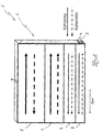
- Fig. 1 shows a schematic representation of the perspective view of a first capacitor according to the invention 1.
- the condenser 1 is formed as a coolant-cooled condenser 1 and consists inter alia of a tube / rib block 2, which in turn is formed of a plurality of flat tubes 3 with intermediate layers 4. Both the flat tubes 3 and the intermediate layers 4 connected to the flat tubes by a soldering process are shown only schematically in the illustration shown here.
- the flat tubes 3 and the intermediate layers 4 extend along the flow path SW.
- the tube / rib block 2 has a construction formed from four tube units 5, 6, 7, 8.
- Each tube unit 5, 6, 7, 8 consists of a plurality of flat tubes 3 and intermediate layers 4.
- the number of flat tubes 3 and intermediate layers 4 and the hydraulic diameter and flow of coolant and refrigerant are adapted to the respective flow velocities.
- the number of flat tubes 3 or of the intermediate layers 4, starting from the tube unit 5 to the tube unit 8 decreases steadily.
- the adjacent in the pipe units 5 and 8 extending flow paths SW thus have substantially opposite directions extending flow directions (flow paths) on.
- two water-side flow paths are shown, wherein the two refrigerant flow paths 5, 6 are connected to a first and the refrigerant flow paths 7, 8 with a second water-side flow path.
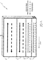
- Fig. 2 shows a second embodiment of a capacitor 1 '.
- the capacitor 1 ' corresponds in its construction substantially to the capacitor 1 according to Fig. 1 ,
- the condenser 1 ' has four tube units 5', 6 ', 7', 8 ', wherein the flow paths SW' of the refrigerant (dashed line) and the coolant (solid line) in contrast to the in Fig. 1 shown condenser 1 in all four tube units 5 ', 6', 7 ', 8' are in countercurrent.
- the flow paths SW 'extending in the tube units 5', 6 ', 7', 8 'thus have essentially opposite directions of flow.
- the flat tube 3 has six flow channels 10, 11, 12, 13, 14, 15 with the same flow cross-section or the same hydraulic diameter (D h refrigerant ) extending in the tube longitudinal direction.
- the refrigerant-side flow channels 10, 11, 12, 13, 14, 15 have a substantially rectangular cross-sectional shape, wherein the width b of each flow channel is preferably at least slightly smaller than its height h.
- the webs 16, 17, 18, 19, 20 have a sufficient to ensure the stability of the flat tube 3 minimum thickness.
- the minimum thickness to be selected can be, for example, the total depth t of the flat tube 3 or by the selected hydraulic Diameter (D h refrigerant ) of the flow channels 10, 11, 12, 13, 14, 15 result.
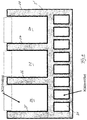
- Fig. 4 shows a further embodiment of a flat tube 3 '.
- the flat tube 3 ' essentially has a plurality of identically formed flow channels 21 and four webs 25, 26, 27, 28 defining the intermediate layer 22, 23, 24.
- the flat tube 3 'thus consists of a combination flat tube / liner.
- a one-piece production or design may be provided.
- the webs 25, 26, 27, 28 may be designed as separate components for forming the intermediate layers (intermediate elements) 22, 23, 24, which are connected to the flat tube 3 'in a further operation, for example by a soldering process ,
Landscapes
- Engineering & Computer Science (AREA)
- Physics & Mathematics (AREA)
- Thermal Sciences (AREA)
- Mechanical Engineering (AREA)
- General Engineering & Computer Science (AREA)
- Geometry (AREA)
- Heat-Exchange Devices With Radiators And Conduit Assemblies (AREA)
- Air-Conditioning For Vehicles (AREA)
Description
- Die Erfindung betrifft einen kühlmittelgekühlten Kondensator, gemäß dem Oberbegriff des Anspruchs 1.
WO 2009/013179 offenbart einen derartigen Kondensator. - Ein Kondensator dient bei Wärmekraftmaschinen und in Kälteanlagen zur Verflüssigung des Abdampfes bzw. des dampfförmigen Kältemittels. Dies ermöglicht in den genannten Anlagen einen geschlossenen Kreisprozess. In einem Kondensator einer Klimaanlage wird die bei der Kühlung eines Innenraumes aufgenommene Wärmeenergie wieder an die Umgebung abgeführt. Während im klassischen luftgekühlten Kondensator die Wärme an die Luft abgeführt wird, trägt man bei kühlmittelgekühlten Kondensatoren die Wärme in einen zwischengeschalteten Wasserkreislauf ein. Gattungsgemäße Kondensatoren sind aus dem Stand der Technik bekannt.
- Beispielsweise offenbart die
WO 2004 04 2293 A1 einen Kondensator innerhalb eines Luftklimatisierungskreislaufs. DieWO 2001 088 454 A1 offenbart ferner eine Kraftfahrzeug-Kondensatoranordnung und ein Wärmetauschersystem. Ferner sind aus dem Stand der Technik diverse Ausführungen eines indirekten Kondensators für Kraftfahrzeug-Anwendungen auf Basis einer Stapelscheibenanordnung bekannt. - Die aus dem Stand der Technik bekannten Lösungen weisen jedoch zumeist mehrere Nachteile auf. So weisen bei der Stapelscheibenanordnung in der Regel beide Strömungswege den gleichen hydraulischen Durchmesser auf. Dadurch wird jedoch entweder der Querschnitt der Kühlwasserseite zu klein ausgelegt, was hohe wasserseitige Druckabfälle zur Folge hat oder die hydraulischen Durchmesser für die Kältemittelseite sind zu hoch für eine optimale Auslegung.
- Der Erfindung liegt die Aufgabe zugrunde, einen Kondensator der eingangs genannten Art zu schaffen, mit dem es ermöglicht wird, das zur Verfügung stehende Kühlwasser für eine optimale Wärmeübertragung von Kältemittel zum Kühlmittel zu nutzen, ohne dabei zu hohe Druckabfälle zu erzeugen. Ferner soll der bei der Kondensation vorliegende Temperaturverlauf vorteilhafter ausgeführt werden können.
- Diese Aufgabe wird gelöst durch einen Kondensator mit den Merkmalen des Anspruchs 1. Vorteilhafte Ausgestaltungen sind Gegenstand der Unteransprüche.
- Gelöst wird die Aufgabe erfindungsgemäß dadurch, dass das Verhältnis der beiden hydraulischen Durchmesser (Dh Kühlmittel) zu (Dh Kältemittel) größer (>) 1,3 beträgt. Durch das angegebene Verhältnis der beiden hydraulischen Durchmesser zueinander bzw. durch bestimmte vorteilhafte Geometrieparameter kann der Wärmeübergang erhöht und zugleich der kühlmittelseitige Druckabfall reduziert werden. Der hydraulische Durchmesser Dh ist eine theoretische Größe, um Berechnungen an Rohren oder Kanälen mit nicht kreisförmigem Querschnitt durchzuführen. Mit dem Term

- Er ist der Quotient aus dem vierfachen Strömungsquerschnitt A und dem vom Fluid benetzten Umfang U (ggf. innen und außen) eines Messquerschnitts.
- Der Anmelder hat herausgefunden, dass das Verhältnis der beiden hydraulischen Durchmesser (Dh Kühlmittel) zu (Dh Kältemittel) größer 1,3 betragen soll. Eine weiter vorteilhafte Wirkung erzielt ein Kondensator, wenn das Verhältnis zwischen 1, 3 und 4, und weiter bevorzugt zwischen 1,5 und 2,5 beträgt. Dies hat sich in entsprechend durchgeführten Versuchen des Anmelders gezeigt.
- Beispielsweise kann der hydraulische Durchmesser (Dh Kühlmittel) zwischen 1,5 mm und 3 mm betragen. Der hydraulische Durchmesser (Dh Kühlmittel) definiert sich beispielsweise über ein Zwischenelement, welches in der Art einer Turbulenzeinlage ausgebildet sein kann. Das Zwischenelement weist dabei einen hydraulischen Durchmesser zwischen 1,5 mm und 3 mm auf. Erfindungsgemäß sind das Flachrohr und das Zwischenelement wärmeleitend miteinander verbunden, beispielsweise verlötet. Es findet somit eine Kombination zwischen Flachrohr und Zwischenlage statt, durch die das Kühlmittel im Gegen- oder Gleichstrom am Flachrohr vorbeigeführt wird. Dies ist ein Vorteil gegenüber bekannten Lösungen in Plattenbauweise, welche gleiche hydraulische Durchmesser aufweisen. Bei der erfindungsgemäßen Lösung hat sich gezeigt, dass durch eine Erhöhung des Querschnittes auf der Kühlmittelseite und einer Verringerung des Querschnittes auf der Kältemittelseite Wärmeübergang und Druckabfall optimiert werden können.
- Eine bevorzugte Ausführungsform zur Erlangung des angegeben kältemittelseitigen Strömungsquerschnittes ist beispielsweise ein Flachrohr mit einer Mehrzahl von Strömungskanälen. Beispielsweise kann der hydraulische Durchmesser (Dh Kältemittel) zwischen 0,2 mm und 1,8 mm, bevorzugt zwischen 0,4 mm und 1,3 mm, betragen. Bevorzugt weist der Strömungsquerschnitt der kältemittelseitigen Strömungskanäle eine im Wesentlichen rechteckige Querschnittsform auf, wobei die Breite b eines jeden Strömungskanals vorzugsweise zumindest geringfügig kleiner als seine Höhe h ist. Für die Kältemittelströmung werden bevorzugt extrudierte Flachrohre eingesetzt. Diese bestehen beispielsweise aus einem Rohrmantel und weisen zur Erhöhung der Festigkeit und zur Erhöhung der Wärmeübertragungsfläche Innenstege auf. Ein bevorzugtes Rohr weist eine größere Höhe als Breite auf, da in diesem Fall durch Kapillareffekte ein zusätzlicher Leistungsvorteil erzielt werden kann. Der Strömungsquerschnitt eines jeden Rohres wird dabei durch den hydraulischen Durchmesser charakterisiert.
- Eine weitere bevorzugte Ausführungsform sieht vor, dass sowohl die kühlmittel- als auch die kältemittelseitigen Strömungspfade im Strömungsverlauf betrachtet eine Mehrzahl von Umlenkungen aufweisen können. Insbesondere durch die kältemittelseitigen Umlenkungen ist es dabei möglich, eine Verschaltung aufzubauen sowie die Dichteänderung des Kältemittels bei der Kondensation zu kompensieren und die treibenden Temperaturdifferenzen zu optimieren.
- Ferner kann vorgesehen sein, dass der kältemittelseitige Strömungspfad degressiv verschaltet ist, dergestalt, dass der Strömungsquerschnitt des letzten kältemittelseitigen Strömungspfades zumindest geringfügig kleiner ist als der kältemittelseitige Strömungspfad des ersten Strömungspfades. Der Begriff degressiv bedeutet hierbei die Beziehung zwischen zwei Größen z.B. wenn die hydraulischen Durchmesser und Stromführungen von Kühlmittel und Kältemittel an die jeweiligen Strömungsgeschwindigkeiten angepasst sind bzw. wenn beim Steigen der einen Größe jeweils auch die andere steigt. Im Kondensator selbst wird das Kältemittel erst bis auf seine Kondensationstemperatur abgekühlt. Anschließend erfolgt die Kondensation des Kältemittels vor einer weiteren Unterkühlung des Kältemittels auf eine Temperatur unterhalb der Kondensationstemperatur. Bei diesem Prozess nimmt das spezifische Volumen des Kältemittels erheblich (d.h. auf 1/10-1/20 des Ausgangsvolumens) ab. Um dieser Volumenabnahme Rechnung zu tragen, wird die Kältemittelströmung in mehreren hintereinander angeordneten Strömungspfaden durch das Bauteil geführt, die eine von Pfad zu Pfad abnehmende Strömungsquerschnittsfläche aufweisen (--> degressive Verschaltung). Das wird dadurch erreicht, dass die Anzahl an Rohren, die in einem Pfad parallel geschaltet werden, von Pfad zu Pfad abnimmt.
- Wie bereits beschrieben, wird das Kältemittel erst enthitzt, dann im Bauteil kondensiert (wobei hier über einen weiten Bereich die Temperatur konstant bleibt) und anschließend unterkühlt. Daher stellen sich in der Praxis folgende Anforderungen an die Führung der Kühlmittelströmung:
- das Kühlmittel sollte im Bereich der Unterkühlung in den Kondensator eingeleitet werden und dann im Gegenstrom geführt werden;
- im Bereich der Kondensation ist durch die konstante Temperatur auf der Kältemittelseite egal, ob die Strömung im Gegen- oder Gleichstrom geführt wird;
- das Kältemittel sollte im Bereich der Überhitzung im Gegenstrom aus dem Apparat geführt werden.
- Dadurch wird das treibende Temperaturgefälle im Wärmeübertrager/Kondensator optimiert und somit eine hohe Leistung erzielt. Wie schon beschrieben, weist die Kältemittelseite hierbei eine degressive Verschaltung auf, während die Kühlmittelseite nahezu keine Veränderung im spezifischen Volumen aufweist, so dass hier bei optimaler Verschaltung im Wesentlichen gleichmäßige Strömungsquerschnitte vorgesehen sind.
- Beispielsweise kann es sich bei dem eingesetzten Kältemittel bevorzugt um R-1234yf und bei dem eingesetzten Kühlmittel bevorzugt um Wasser-Glysanthin (je nach Verdünnungsgrad mit Wasser ist Glysanthin bis unter -40 Grad Celsius frostsicher. Zudem schützt es vor Korrosion) handeln. R-1234yf ist mit einem GWP-Faktor von lediglich 4 um das 357-fache klimafreundlicher als bekannte gängige Kältemittel und unterschreitet den Grenzwert von 150 GWP um 97 Prozent. Im Vergleich zu CO2 als Kühlmittel arbeitet es vor allem bei höheren Temperaturen effizienter.
- Eine weitere bevorzugte Ausführungsform sieht vor, dass sich zumindest im ersten und im letzten Strömungsweg, bevorzugt jedoch in allen Strömungswegen, die kühlmittelseitigen Strömungspfade und die kältemittelseitigen Strömungspfade im Gegenstrom befinden können.
- Eine Ausführungsform der Erfindung sieht ferner die Optimierung der Bautiefe einer Rohr-/Rippeneinheit vor. So kann beispielsweise die Tiefe t jeweils einer Rohr-/Rippeneinheit bzw. eines jeden Flachrohres bzw. einer jeden Zwischenlage zwischen 10 mm und 100 mm, bevorzugt zwischen 16 mm und 35 mm, betragen.
- Die hier aufgezeigte Lösung ist vorteilhafterweise kostengünstig herstellbar und weist eine kompakte Ausgestaltung auf.
- Weitere Vorteile, Merkmale und Einzelheiten der Erfindung ergeben sich aus der nachfolgenden Beschreibung, in der unter Bezugnahme auf die Zeichnungen Ausführungsbeispiele der Erfindung beschrieben sind. Dabei können die in den Ansprüchen und in der Beschreibung erwähnten Merkmale jeweils einzeln für sich oder in beliebiger Kombination erfindungswesentlich sein.
- Es zeigen:
- Fig. 1
- in schematischer Darstellung die perspektivische Ansicht auf einen aus mehreren Flachrohren gebildeten ersten erfindungsgemäßen Kondensator;
- Fig. 2
- in schematischer Darstellung die perspektivische Ansicht auf einen aus mehreren Flachrohren gebildeten zweiten erfindungsgemäßen Kondensator;
- Fig. 3
- in schematischer Darstellung die Ansicht auf die Stirnseite eines erfindungsgemäßen Flachrohres;
- Fig. 4
- die schematische Darstellung einer weiteren Ausführungsform eines erfindungsgemäßen Flachrohres zur Bildung eines Rohr-/Rippenblocks.
-
Fig. 1 zeigt in schematischer Darstellung die perspektivische Ansicht auf einen ersten erfindungsgemäßen Kondensator 1. Der Kondensator 1 ist als kühlmittelgekühlter Kondensator 1 ausgebildet und besteht u.a. aus einem Rohr-/Rippenblock 2, der wiederum aus mehreren Flachrohren 3 mit Zwischenlagen 4 gebildet wird. Sowohl die Flachrohre 3 als auch die mit den Flachrohren durch einen Lötvorgang verbundenen Zwischenlagen 4 sind in der hier gezeigten Darstellung nur schematisch dargestellt. Die Flachrohre 3 bzw. die Zwischenlagen 4 verlaufen längs des Strömungsweges SW. - Der Rohr-/Rippenblock 2 weist bei der hier gezeigten Ausführungsform einen aus vier Rohreinheiten 5, 6, 7, 8 gebildeten Aufbau auf. Jede Rohreinheit 5, 6, 7, 8 besteht aus einer Mehrzahl von Flachrohren 3 bzw. Zwischenlagen 4. Die Anzahl der Flachrohre 3 und Zwischenlagen 4 sowie die hydraulischen Durchmesser und Stromführungen von Kühlmittel und Kältemittel sind an die jeweiligen Strömungsgeschwindigkeiten angepasst. So nehmen beispielsweise die Anzahl der Flachrohre 3 bzw. der Zwischenlagen 4 ausgehend von der Rohreinheit 5 bis Rohreinheit 8 beständig ab.
- Bei der hier gezeigten Ausführungsform befinden sich die Strömungswege SW des Kältemittels (gestrichelte Linie) sowie des Kühlmittels (durchgezogene Linie) in den Rohreinheiten 5 und 8 unter Anwendung mehrerer Umlenkungen im Gegenstrom. Die in den Rohreinheiten 5 und 8 benachbart verlaufenden Strömungswege SW weisen somit im Wesentlichen gegenläufig verlaufende Strömungsrichtungen (Strömungspfade) auf. In dieser Ausführungsform sind zwei wasserseitige Strömungswege dargestellt, wobei die beiden Kältemittelströmungswege 5, 6 mit einem ersten und die Kältemittelströmungswege 7, 8 mit einem zweiten wasserseitigen Strömungsweg verbunden sind.
-
Fig. 2 zeigt eine zweite Ausführungsform eines Kondensators 1'. Der Kondensator 1' entspricht in seinem Aufbau im Wesentlichen dem Kondensator 1 gemäßFig. 1 . - Auch der Kondensator 1' weist vier Rohreinheiten 5', 6', 7', 8' auf, wobei sich die Strömungswege SW' des Kältemittels (gestrichelte Linie) sowie des Kühlmittels (durchgezogene Linie) im Gegensatz zu dem in
Fig. 1 gezeigten Kondensator 1 in allen vier Rohreinheiten 5', 6', 7', 8' im Gegenstrom befinden. Die in den Rohreinheiten 5', 6', 7', 8' benachbart verlaufenden Strömungswege SW' weisen somit im Wesentlichen gegenläufig verlaufende Strömungsrichtungen auf. -
Fig. 3 zeigt in schematischer Darstellung die Ansicht auf die Stirnseite eines Flachrohres 3. Das Flachrohr 3 weist sechs in Rohrlängsrichtung verlaufende Strömungskanäle 10, 11, 12, 13, 14, 15 gleichen Strömungsquerschnitts bzw. gleichen hydraulischen Durchmessers (Dh Kältemittel) auf. Die kältemittelseitigen Strömungskanäle 10, 11, 12, 13, 14, 15 weisen eine im Wesentlichen rechteckige Querschnittsform auf, wobei die Breite b eines jeden Strömungskanals vorzugsweise zumindest geringfügig kleiner als seine Höhe h ist. - Zwischen den Strömungskanälen 10, 11, 12, 13, 14, 15 bilden sich Stege 16, 17, 18, 19, 20 aus. Die Stege 16, 17, 18, 19, 20 weisen dabei eine zur Gewährleistung der Stabilität des Flachrohres 3 ausreichende Mindeststärke auf. Die zu wählende Mindeststärke kann sich beispielsweise durch die Gesamttiefe t des Flachrohres 3 bzw. durch den gewählten hydraulischen Durchmesser (Dh Kältemittel) der Strömungskanäle 10, 11, 12, 13, 14, 15 ergeben.
-
Fig. 4 zeigt eine weitere Ausführungsform eines Flachrohres 3'. Das Flachrohr 3' weist im Wesentlichen mehrere gleich ausgebildete Strömungskanäle 21 sowie vier die Zwischenlage 22, 23, 24 definierende Stege 25, 26, 27, 28 auf. Das Flachrohr 3' besteht somit aus einer Kombination Flachrohr/Zwischenlage. Beispielsweise kann eine einstückige Fertigung bzw. Ausgestaltung vorgesehen sein. Es wäre jedoch auch denkbar, die Stege 25, 26, 27, 28 zur Bildung der Zwischenlagen (Zwischenelemente) 22, 23, 24 als separate Bauteile auszuführen, welche in einem weiteren Arbeitsgang, beispielsweise durch einen Lötvorgang, mit dem Flachrohr 3' verbunden werden.
Claims (11)
- Kühlmittelgekühlter Kondensator (1, 1'), bestehend aus zumindest einem Rohr-/Rippenblock (2) mit mehreren Flachrohren (3, 3'), wobei jedes Flachrohr (3, 3') eine Mehrzahl von in Rohrquerrichtung nebeneinanderliegend verlaufende, einen kältemittelseitigen hydraulischen Durchmesser (Dh Kältemittel) definierende Strömungskanäle (10, 11, 12, 13, 14, 15, 21) aufweist, und wobei im Bereich der Flachrohre (3, 3') zumindest jeweils ein, einen kühlmittelseitigen hydraulischen Durchmesser (Dh Kühlmittel) definierendes Zwischenelement (4) angeordnet ist, wobei das Verhältnis der beiden hydraulischen Durchmesser (Dh Kühlmittel) zu (Dh Kältemittel) größer (>) 1,3 beträgt, dadurch gekennzeichnet, dass das Flachrohr und das Zwischenelement wärmeleitend miteinander verbunden sind, wobei eine Kombination zwischen Flachrohr und Zwischenlage stattfindet, durch die das Kühlmittel am Flachrohr im Gegenstrom oder Gleichstrom vorbei geführt wird.
- Kondensator nach Anspruch 1, dadurch gekennzeichnet, dass das Verhältnis der beiden hydraulischen Durchmesser (Dh Kühlmittel) zu (Dh Käl-temittel) zwischen 1,3 und 4, bevorzugt zwischen 1,5 und 2,5, beträgt.
- Kondensator nach Anspruch 1 und/oder 2, dadurch gekennzeichnet, dass der hydraulische Durchmesser (Dh Kühlmittel) zwischen 1,5 mm und 3 mm beträgt.
- Kondensator nach Anspruch 1 und/oder 2, dadurch gekennzeichnet, dass der hydraulische Durchmesser (Dh Kältemittel) zwischen 0,2 mm und 1,8 mm, bevorzugt zwischen 0,4 mm und 1,3 mm, beträgt.
- Kondensator nach zumindest einem der vorhergehenden Ansprüche, dadurch gekennzeichnet, dass das Zwischenelement (4) in der Art einer Turbulenzeinlage ausgebildet ist.
- Kondensator nach zumindest einem der vorhergehenden Ansprüche, dadurch gekennzeichnet, dass die Flachrohre (3, 3') eine Mehrzahl von nebeneinander angeordneten gleichgerichteten und gleich ausgebildeten Strömungskanälen (10, 11, 12, 13, 14, 15, 21) aufweisen, wobei die Breite b eines jeden Strömungskanals (10, 11, 12, 13, 14, 15, 21) zumindest geringfügig kleiner als seine Höhe h ist.
- Kondensator nach zumindest einem der vorhergenden Ansprüche, dadurch gekennzeichnet, dass sowohl die kühlmittel- als auch die kältemittelseitigen Strömungspfade im Strömungsverlauf betrachtet eine Mehrzahl von Umlenkungen aufweisen.
- Kondensator nach zumindest einem der vorhergehenden Ansprüche, dadurch gekennzeichnet, dass der kältemittelseitige Strömungspfad degressiv verschaltet ist, dergestalt, dass der Strömungsquerschnitt des letzten kältemittelseitigen Strömungspfades zumindest geringfügig kleiner ist als der kältemittelseitige Strömungspfad des ersten Strömungspfades.
- Verwendung eines Kondensators nach zumindest einem der vorhergehenden Ansprüche, dadurch gekennzeichnet, dass sich mindestens ein kältemittelseitiger Strömungspfad und ein kühlmittelseitiger Strömungspfad im Gegenstrom befinden.
- Verwendung eines Kondensators nach Anspruch 9 dadurch gekennzeichnet, dass sich zumindest im ersten und im letzten Strömungsweg (SW, SW'), bevorzugt jedoch in allen Strömungswegen (SW, SW'), die kühlmittelseitigen Strömungspfade und die kältemittelseitigen Strömungspfade im Gegenstrom befinden.
- Kondensator nach zumindest einem der Ansprüche 1 bis 8, dadurch gekennzeichnet, dass die Tiefe t jeweils einer Rohr-/Rippeneinheit (2) bzw. eines Flachrohres (3, 3') zwischen 10 mm und 100 mm, bevorzugt zwischen 16 mm und 35 mm, beträgt.
Applications Claiming Priority (2)
| Application Number | Priority Date | Filing Date | Title |
|---|---|---|---|
| DE102011007784A DE102011007784A1 (de) | 2011-04-20 | 2011-04-20 | Kondensator |
| PCT/EP2012/057174 WO2012143451A1 (de) | 2011-04-20 | 2012-04-19 | Kondensator |
Publications (2)
| Publication Number | Publication Date |
|---|---|
| EP2699864A1 EP2699864A1 (de) | 2014-02-26 |
| EP2699864B1 true EP2699864B1 (de) | 2018-10-24 |
Family
ID=45998351
Family Applications (1)
| Application Number | Title | Priority Date | Filing Date |
|---|---|---|---|
| EP12715990.3A Not-in-force EP2699864B1 (de) | 2011-04-20 | 2012-04-19 | Kondensator |
Country Status (5)
| Country | Link |
|---|---|
| US (1) | US10107566B2 (de) |
| EP (1) | EP2699864B1 (de) |
| CN (1) | CN203772062U (de) |
| DE (1) | DE102011007784A1 (de) |
| WO (1) | WO2012143451A1 (de) |
Families Citing this family (4)
| Publication number | Priority date | Publication date | Assignee | Title |
|---|---|---|---|---|
| DE102013003414B4 (de) * | 2013-02-28 | 2019-10-31 | Webasto SE | Wärmeübertrager |
| DE102013225321A1 (de) | 2013-12-09 | 2015-06-11 | MAHLE Behr GmbH & Co. KG | Stapelscheibe für einen Wärmeübertrager und Wärmeübertrager |
| DE102015103177A1 (de) | 2015-03-05 | 2016-09-08 | Halla Visteon Climate Control Corporation | Hochdruckkältemittelwärmeübertrager mit Mehrkanalflachrohren |
| JPWO2020179651A1 (ja) * | 2019-03-01 | 2021-11-04 | 株式会社ヴァレオジャパン | 車両用バッテリの冷却モジュール |
Citations (10)
| Publication number | Priority date | Publication date | Assignee | Title |
|---|---|---|---|---|
| EP0559983A1 (de) | 1992-03-11 | 1993-09-15 | Modine Manufacturing Company | Verdampfer oder Verdampfer/Verflüssiger |
| GB2346680A (en) | 1999-02-11 | 2000-08-16 | Llanelli Radiators Ltd | Condenser |
| US6125922A (en) | 1992-11-25 | 2000-10-03 | Nippondenso Co., Ltd. | Refrigerant condenser |
| EP1068967A1 (de) | 1999-07-12 | 2001-01-17 | Valeo Climatisation | Heiz- Klimaanlage für Kraftfahrzeuge |
| US20050194123A1 (en) | 2004-03-05 | 2005-09-08 | Roland Strahle | Plate heat exchanger |
| US20060053833A1 (en) | 2002-10-31 | 2006-03-16 | Carlos Martins | Condenser, in particular for a motor vehicle air conditioning circuit, and circuit comprising same |
| US20070261420A1 (en) | 2004-06-17 | 2007-11-15 | Behr Gmbh & Co. Kg | Method and Device for Controlling a Coolant Circuit of an Air Conditioning System for a Vehicle |
| WO2008061918A1 (fr) | 2006-11-21 | 2008-05-29 | Valeo Systemes Thermiques | Echangeur de chaleur interne pour circuit de fluide refrigerant |
| WO2009013179A2 (en) | 2007-07-23 | 2009-01-29 | M.T.A. S.P.A. | Heat exchanger with mini- and/or micro-channels and method for its construction |
| DE202010000951U1 (de) | 2010-01-22 | 2010-04-22 | Behr Gmbh & Co. Kg | Wärmeübertrager, insbesondere Gaskühler für Klimaanlagen in Kraftfahrzeugen |
Family Cites Families (31)
| Publication number | Priority date | Publication date | Assignee | Title |
|---|---|---|---|---|
| US4998580A (en) * | 1985-10-02 | 1991-03-12 | Modine Manufacturing Company | Condenser with small hydraulic diameter flow path |
| US4825941B1 (en) * | 1986-07-29 | 1997-07-01 | Showa Aluminum Corp | Condenser for use in a car cooling system |
| US5190100B1 (en) * | 1986-07-29 | 1994-08-30 | Showa Aluminum Corp | Condenser for use in a car cooling system |
| US5529116A (en) * | 1989-08-23 | 1996-06-25 | Showa Aluminum Corporation | Duplex heat exchanger |
| US5080167A (en) * | 1990-06-12 | 1992-01-14 | General Motors Corporation | Combination radiator and condenser apparatus for motor vehicle |
| JP3017272B2 (ja) * | 1990-11-07 | 2000-03-06 | 株式会社ゼクセル | 熱交換器 |
| DE69719489T2 (de) * | 1996-12-04 | 2003-12-24 | Toyo Radiator Co., Ltd. | Wärmetauscher |
| US6209628B1 (en) * | 1997-03-17 | 2001-04-03 | Denso Corporation | Heat exchanger having several heat exchanging portions |
| KR100264815B1 (ko) * | 1997-06-16 | 2000-09-01 | 신영주 | 다단기액분리형응축기 |
| US6216776B1 (en) * | 1998-02-16 | 2001-04-17 | Denso Corporation | Heat exchanger |
| EP1065454A1 (de) * | 1999-07-02 | 2001-01-03 | Modine Manufacturing Company | Luftgekühlter Kondensator |
| EP1167909A3 (de) * | 2000-02-08 | 2005-10-12 | Calsonic Kansei Corporation | Struktur eines kombinierten Wärmetauscherkerns |
| US6561264B2 (en) * | 2000-03-16 | 2003-05-13 | Denso Corporation | Compound heat exhanger having cooling fins introducing different heat exhanging performances within heat exchanging core portion |
| JP2001304701A (ja) * | 2000-04-19 | 2001-10-31 | Denso Corp | ヒートポンプ式温水器 |
| GB0012033D0 (en) | 2000-05-19 | 2000-07-05 | Llanelli Radiators Ltd | Condenser arrangement and heat exchanger system |
| JP2002277180A (ja) * | 2001-03-16 | 2002-09-25 | Calsonic Kansei Corp | 一体型熱交換器のコア部構造 |
| JP3945208B2 (ja) * | 2001-10-09 | 2007-07-18 | 株式会社デンソー | 熱交換用チューブ及び熱交換器 |
| US6793012B2 (en) * | 2002-05-07 | 2004-09-21 | Valeo, Inc | Heat exchanger |
| EP1546630A4 (de) * | 2002-10-02 | 2010-11-24 | Showa Denko Kk | WûRMEAUSTAUSCHROHR UND WûRMEAUSTAUSCHER |
| JP4037241B2 (ja) * | 2002-10-24 | 2008-01-23 | カルソニックカンセイ株式会社 | コルゲートフィン |
| JP4166591B2 (ja) * | 2003-02-13 | 2008-10-15 | カルソニックカンセイ株式会社 | 熱交換器 |
| US7337832B2 (en) * | 2003-04-30 | 2008-03-04 | Valeo, Inc. | Heat exchanger |
| US6904963B2 (en) * | 2003-06-25 | 2005-06-14 | Valeo, Inc. | Heat exchanger |
| KR100518856B1 (ko) * | 2003-09-04 | 2005-09-30 | 엘지전자 주식회사 | 플랫 튜브 열 교환기 |
| JP2009166529A (ja) * | 2008-01-11 | 2009-07-30 | Calsonic Kansei Corp | 車両用凝縮器 |
| US8759551B2 (en) * | 2008-03-14 | 2014-06-24 | Dic Corporation | Process for producing epoxy (metha)acrylate |
| US9233197B2 (en) * | 2008-10-10 | 2016-01-12 | Gambro Lundia Ab | Heat exchanger and method for heat exchanging |
| US9335077B2 (en) * | 2008-10-20 | 2016-05-10 | Keihin Thermal Technology Corporation | Condenser with first header tank and second header tank provided on one side of the condenser |
| FR2950682B1 (fr) * | 2009-09-30 | 2012-06-01 | Valeo Systemes Thermiques | Condenseur pour vehicule automobile a integration amelioree |
| JP5655676B2 (ja) * | 2010-08-03 | 2015-01-21 | 株式会社デンソー | 凝縮器 |
| JP6073601B2 (ja) * | 2011-09-02 | 2017-02-01 | サンデンホールディングス株式会社 | ヒートポンプシステム |
-
2011
- 2011-04-20 DE DE102011007784A patent/DE102011007784A1/de not_active Withdrawn
-
2012
- 2012-04-19 EP EP12715990.3A patent/EP2699864B1/de not_active Not-in-force
- 2012-04-19 US US14/112,998 patent/US10107566B2/en not_active Expired - Fee Related
- 2012-04-19 WO PCT/EP2012/057174 patent/WO2012143451A1/de not_active Ceased
- 2012-04-19 CN CN201290000436.5U patent/CN203772062U/zh not_active Expired - Fee Related
Patent Citations (10)
| Publication number | Priority date | Publication date | Assignee | Title |
|---|---|---|---|---|
| EP0559983A1 (de) | 1992-03-11 | 1993-09-15 | Modine Manufacturing Company | Verdampfer oder Verdampfer/Verflüssiger |
| US6125922A (en) | 1992-11-25 | 2000-10-03 | Nippondenso Co., Ltd. | Refrigerant condenser |
| GB2346680A (en) | 1999-02-11 | 2000-08-16 | Llanelli Radiators Ltd | Condenser |
| EP1068967A1 (de) | 1999-07-12 | 2001-01-17 | Valeo Climatisation | Heiz- Klimaanlage für Kraftfahrzeuge |
| US20060053833A1 (en) | 2002-10-31 | 2006-03-16 | Carlos Martins | Condenser, in particular for a motor vehicle air conditioning circuit, and circuit comprising same |
| US20050194123A1 (en) | 2004-03-05 | 2005-09-08 | Roland Strahle | Plate heat exchanger |
| US20070261420A1 (en) | 2004-06-17 | 2007-11-15 | Behr Gmbh & Co. Kg | Method and Device for Controlling a Coolant Circuit of an Air Conditioning System for a Vehicle |
| WO2008061918A1 (fr) | 2006-11-21 | 2008-05-29 | Valeo Systemes Thermiques | Echangeur de chaleur interne pour circuit de fluide refrigerant |
| WO2009013179A2 (en) | 2007-07-23 | 2009-01-29 | M.T.A. S.P.A. | Heat exchanger with mini- and/or micro-channels and method for its construction |
| DE202010000951U1 (de) | 2010-01-22 | 2010-04-22 | Behr Gmbh & Co. Kg | Wärmeübertrager, insbesondere Gaskühler für Klimaanlagen in Kraftfahrzeugen |
Also Published As
| Publication number | Publication date |
|---|---|
| US20140054016A1 (en) | 2014-02-27 |
| WO2012143451A1 (de) | 2012-10-26 |
| CN203772062U (zh) | 2014-08-13 |
| DE102011007784A1 (de) | 2012-10-25 |
| EP2699864A1 (de) | 2014-02-26 |
| US10107566B2 (en) | 2018-10-23 |
Similar Documents
| Publication | Publication Date | Title |
|---|---|---|
| DE69428219T2 (de) | Plattenwärmetauscher | |
| DE3780648T2 (de) | Kondensator. | |
| DE69911131T2 (de) | Wärmetauscher | |
| DE102011108892B4 (de) | Kondensator | |
| EP0374895A2 (de) | Verflüssiger für ein Kältemittel einer Fahrzeugklimaanlage | |
| DE102010008176B4 (de) | Wärmeübertrager und Verfahren zum Betreiben eines Wärmeübertragers | |
| EP2699864B1 (de) | Kondensator | |
| DE112005001885T5 (de) | Wärmetauscher, Zwischenwärmetauscher und Kältekreislauf | |
| EP1411310B1 (de) | Wärmeübertrager in Serpentinenbauweise | |
| EP2926073B1 (de) | Wärmeübertrager | |
| EP2606292B1 (de) | Kältemittelkondensatorbaugruppe | |
| DE102004001786A1 (de) | Wärmeübertrager, insbesondere für überkritischen Kältekreislauf | |
| DE4033636A1 (de) | Waermetauscher, insbesondere verfluessiger und verdampfer fuer fahrzeuge - klimaanlagen | |
| EP3009780B1 (de) | Wärmeübertrager | |
| DE102004047304A1 (de) | Unterkühlender Kondensator | |
| EP1798505A2 (de) | Wärmetauscher, insbesondere Verdampfer | |
| DE3843306A1 (de) | Flachrohrverfluessiger fuer ein kaeltemittel einer fahrzeugklimaanlage | |
| DE102005016540A1 (de) | Mehrkanalflachrohr | |
| DE9014655U1 (de) | Wärmetauscher, insbesondere Verflüssiger und Verdampfer für Fahrzeug - Klimaanlagen | |
| EP2606291B1 (de) | Kältemittelkondensatorbaugruppe | |
| DE112018001493T5 (de) | Wärmetauscher | |
| DE202010000951U1 (de) | Wärmeübertrager, insbesondere Gaskühler für Klimaanlagen in Kraftfahrzeugen | |
| DE102011005177A1 (de) | Kondensator | |
| DE102005028510A1 (de) | Verstellbarer innerer Wärmeübertrager | |
| EP2253493B1 (de) | Vorrichtung zur Beheizung des Innenraumes eines Kraftfahrzeuges |
Legal Events
| Date | Code | Title | Description |
|---|---|---|---|
| PUAI | Public reference made under article 153(3) epc to a published international application that has entered the european phase |
Free format text: ORIGINAL CODE: 0009012 |
|
| 17P | Request for examination filed |
Effective date: 20131120 |
|
| AK | Designated contracting states |
Kind code of ref document: A1 Designated state(s): AL AT BE BG CH CY CZ DE DK EE ES FI FR GB GR HR HU IE IS IT LI LT LU LV MC MK MT NL NO PL PT RO RS SE SI SK SM TR |
|
| DAX | Request for extension of the european patent (deleted) | ||
| RAP1 | Party data changed (applicant data changed or rights of an application transferred) |
Owner name: MAHLE BEHR GMBH & CO. KG |
|
| 17Q | First examination report despatched |
Effective date: 20160509 |
|
| STAA | Information on the status of an ep patent application or granted ep patent |
Free format text: STATUS: EXAMINATION IS IN PROGRESS |
|
| RIC1 | Information provided on ipc code assigned before grant |
Ipc: F28D 1/053 20060101ALN20180426BHEP Ipc: F28F 1/04 20060101ALI20180426BHEP Ipc: F28F 1/02 20060101ALI20180426BHEP Ipc: F28D 21/00 20060101ALN20180426BHEP Ipc: F28D 7/00 20060101AFI20180426BHEP Ipc: F25B 39/04 20060101ALN20180426BHEP |
|
| GRAP | Despatch of communication of intention to grant a patent |
Free format text: ORIGINAL CODE: EPIDOSNIGR1 |
|
| STAA | Information on the status of an ep patent application or granted ep patent |
Free format text: STATUS: GRANT OF PATENT IS INTENDED |
|
| RIC1 | Information provided on ipc code assigned before grant |
Ipc: F28D 1/053 20060101ALN20180515BHEP Ipc: F28F 1/02 20060101ALI20180515BHEP Ipc: F28D 21/00 20060101ALN20180515BHEP Ipc: F28D 7/00 20060101AFI20180515BHEP Ipc: F28F 1/04 20060101ALI20180515BHEP Ipc: F25B 39/04 20060101ALN20180515BHEP |
|
| INTG | Intention to grant announced |
Effective date: 20180601 |
|
| GRAJ | Information related to disapproval of communication of intention to grant by the applicant or resumption of examination proceedings by the epo deleted |
Free format text: ORIGINAL CODE: EPIDOSDIGR1 |
|
| STAA | Information on the status of an ep patent application or granted ep patent |
Free format text: STATUS: EXAMINATION IS IN PROGRESS |
|
| GRAR | Information related to intention to grant a patent recorded |
Free format text: ORIGINAL CODE: EPIDOSNIGR71 |
|
| GRAS | Grant fee paid |
Free format text: ORIGINAL CODE: EPIDOSNIGR3 |
|
| STAA | Information on the status of an ep patent application or granted ep patent |
Free format text: STATUS: GRANT OF PATENT IS INTENDED |
|
| GRAA | (expected) grant |
Free format text: ORIGINAL CODE: 0009210 |
|
| STAA | Information on the status of an ep patent application or granted ep patent |
Free format text: STATUS: THE PATENT HAS BEEN GRANTED |
|
| INTC | Intention to grant announced (deleted) | ||
| RIN1 | Information on inventor provided before grant (corrected) |
Inventor name: WALTER, CHRISTOPH Inventor name: FOERSTER, UWE Inventor name: HOFMANN, HERBERT |
|
| RIC1 | Information provided on ipc code assigned before grant |
Ipc: F28F 1/04 20060101ALI20180910BHEP Ipc: F25B 39/04 20060101ALN20180910BHEP Ipc: F28D 1/053 20060101ALN20180910BHEP Ipc: F28F 1/02 20060101ALI20180910BHEP Ipc: F28D 7/00 20060101AFI20180910BHEP Ipc: F28D 21/00 20060101ALN20180910BHEP |
|
| AK | Designated contracting states |
Kind code of ref document: B1 Designated state(s): AL AT BE BG CH CY CZ DE DK EE ES FI FR GB GR HR HU IE IS IT LI LT LU LV MC MK MT NL NO PL PT RO RS SE SI SK SM TR |
|
| INTG | Intention to grant announced |
Effective date: 20180917 |
|
| REG | Reference to a national code |
Ref country code: GB Ref legal event code: FG4D Free format text: NOT ENGLISH |
|
| REG | Reference to a national code |
Ref country code: CH Ref legal event code: EP |
|
| REG | Reference to a national code |
Ref country code: IE Ref legal event code: FG4D Free format text: LANGUAGE OF EP DOCUMENT: GERMAN |
|
| REG | Reference to a national code |
Ref country code: AT Ref legal event code: REF Ref document number: 1057192 Country of ref document: AT Kind code of ref document: T Effective date: 20181115 |
|
| REG | Reference to a national code |
Ref country code: DE Ref legal event code: R096 Ref document number: 502012013680 Country of ref document: DE |
|
| REG | Reference to a national code |
Ref country code: NL Ref legal event code: MP Effective date: 20181024 |
|
| REG | Reference to a national code |
Ref country code: LT Ref legal event code: MG4D |
|
| PG25 | Lapsed in a contracting state [announced via postgrant information from national office to epo] |
Ref country code: NL Free format text: LAPSE BECAUSE OF FAILURE TO SUBMIT A TRANSLATION OF THE DESCRIPTION OR TO PAY THE FEE WITHIN THE PRESCRIBED TIME-LIMIT Effective date: 20181024 |
|
| PG25 | Lapsed in a contracting state [announced via postgrant information from national office to epo] |
Ref country code: LV Free format text: LAPSE BECAUSE OF FAILURE TO SUBMIT A TRANSLATION OF THE DESCRIPTION OR TO PAY THE FEE WITHIN THE PRESCRIBED TIME-LIMIT Effective date: 20181024 Ref country code: ES Free format text: LAPSE BECAUSE OF FAILURE TO SUBMIT A TRANSLATION OF THE DESCRIPTION OR TO PAY THE FEE WITHIN THE PRESCRIBED TIME-LIMIT Effective date: 20181024 Ref country code: HR Free format text: LAPSE BECAUSE OF FAILURE TO SUBMIT A TRANSLATION OF THE DESCRIPTION OR TO PAY THE FEE WITHIN THE PRESCRIBED TIME-LIMIT Effective date: 20181024 Ref country code: PL Free format text: LAPSE BECAUSE OF FAILURE TO SUBMIT A TRANSLATION OF THE DESCRIPTION OR TO PAY THE FEE WITHIN THE PRESCRIBED TIME-LIMIT Effective date: 20181024 Ref country code: NO Free format text: LAPSE BECAUSE OF FAILURE TO SUBMIT A TRANSLATION OF THE DESCRIPTION OR TO PAY THE FEE WITHIN THE PRESCRIBED TIME-LIMIT Effective date: 20190124 Ref country code: LT Free format text: LAPSE BECAUSE OF FAILURE TO SUBMIT A TRANSLATION OF THE DESCRIPTION OR TO PAY THE FEE WITHIN THE PRESCRIBED TIME-LIMIT Effective date: 20181024 Ref country code: IS Free format text: LAPSE BECAUSE OF FAILURE TO SUBMIT A TRANSLATION OF THE DESCRIPTION OR TO PAY THE FEE WITHIN THE PRESCRIBED TIME-LIMIT Effective date: 20190224 Ref country code: FI Free format text: LAPSE BECAUSE OF FAILURE TO SUBMIT A TRANSLATION OF THE DESCRIPTION OR TO PAY THE FEE WITHIN THE PRESCRIBED TIME-LIMIT Effective date: 20181024 Ref country code: BG Free format text: LAPSE BECAUSE OF FAILURE TO SUBMIT A TRANSLATION OF THE DESCRIPTION OR TO PAY THE FEE WITHIN THE PRESCRIBED TIME-LIMIT Effective date: 20190124 |
|
| PG25 | Lapsed in a contracting state [announced via postgrant information from national office to epo] |
Ref country code: GR Free format text: LAPSE BECAUSE OF FAILURE TO SUBMIT A TRANSLATION OF THE DESCRIPTION OR TO PAY THE FEE WITHIN THE PRESCRIBED TIME-LIMIT Effective date: 20190125 Ref country code: RS Free format text: LAPSE BECAUSE OF FAILURE TO SUBMIT A TRANSLATION OF THE DESCRIPTION OR TO PAY THE FEE WITHIN THE PRESCRIBED TIME-LIMIT Effective date: 20181024 Ref country code: AL Free format text: LAPSE BECAUSE OF FAILURE TO SUBMIT A TRANSLATION OF THE DESCRIPTION OR TO PAY THE FEE WITHIN THE PRESCRIBED TIME-LIMIT Effective date: 20181024 Ref country code: SE Free format text: LAPSE BECAUSE OF FAILURE TO SUBMIT A TRANSLATION OF THE DESCRIPTION OR TO PAY THE FEE WITHIN THE PRESCRIBED TIME-LIMIT Effective date: 20181024 Ref country code: PT Free format text: LAPSE BECAUSE OF FAILURE TO SUBMIT A TRANSLATION OF THE DESCRIPTION OR TO PAY THE FEE WITHIN THE PRESCRIBED TIME-LIMIT Effective date: 20190224 |
|
| REG | Reference to a national code |
Ref country code: DE Ref legal event code: R026 Ref document number: 502012013680 Country of ref document: DE |
|
| PLBI | Opposition filed |
Free format text: ORIGINAL CODE: 0009260 |
|
| PG25 | Lapsed in a contracting state [announced via postgrant information from national office to epo] |
Ref country code: DK Free format text: LAPSE BECAUSE OF FAILURE TO SUBMIT A TRANSLATION OF THE DESCRIPTION OR TO PAY THE FEE WITHIN THE PRESCRIBED TIME-LIMIT Effective date: 20181024 Ref country code: IT Free format text: LAPSE BECAUSE OF FAILURE TO SUBMIT A TRANSLATION OF THE DESCRIPTION OR TO PAY THE FEE WITHIN THE PRESCRIBED TIME-LIMIT Effective date: 20181024 Ref country code: CZ Free format text: LAPSE BECAUSE OF FAILURE TO SUBMIT A TRANSLATION OF THE DESCRIPTION OR TO PAY THE FEE WITHIN THE PRESCRIBED TIME-LIMIT Effective date: 20181024 |
|
| PLAX | Notice of opposition and request to file observation + time limit sent |
Free format text: ORIGINAL CODE: EPIDOSNOBS2 |
|
| 26 | Opposition filed |
Opponent name: VALEO SYSTEMES THERMIQUES Effective date: 20190715 |
|
| PG25 | Lapsed in a contracting state [announced via postgrant information from national office to epo] |
Ref country code: RO Free format text: LAPSE BECAUSE OF FAILURE TO SUBMIT A TRANSLATION OF THE DESCRIPTION OR TO PAY THE FEE WITHIN THE PRESCRIBED TIME-LIMIT Effective date: 20181024 Ref country code: EE Free format text: LAPSE BECAUSE OF FAILURE TO SUBMIT A TRANSLATION OF THE DESCRIPTION OR TO PAY THE FEE WITHIN THE PRESCRIBED TIME-LIMIT Effective date: 20181024 Ref country code: SM Free format text: LAPSE BECAUSE OF FAILURE TO SUBMIT A TRANSLATION OF THE DESCRIPTION OR TO PAY THE FEE WITHIN THE PRESCRIBED TIME-LIMIT Effective date: 20181024 Ref country code: SK Free format text: LAPSE BECAUSE OF FAILURE TO SUBMIT A TRANSLATION OF THE DESCRIPTION OR TO PAY THE FEE WITHIN THE PRESCRIBED TIME-LIMIT Effective date: 20181024 |
|
| PG25 | Lapsed in a contracting state [announced via postgrant information from national office to epo] |
Ref country code: SI Free format text: LAPSE BECAUSE OF FAILURE TO SUBMIT A TRANSLATION OF THE DESCRIPTION OR TO PAY THE FEE WITHIN THE PRESCRIBED TIME-LIMIT Effective date: 20181024 |
|
| REG | Reference to a national code |
Ref country code: CH Ref legal event code: PL |
|
| PLBB | Reply of patent proprietor to notice(s) of opposition received |
Free format text: ORIGINAL CODE: EPIDOSNOBS3 |
|
| REG | Reference to a national code |
Ref country code: BE Ref legal event code: MM Effective date: 20190430 |
|
| GBPC | Gb: european patent ceased through non-payment of renewal fee |
Effective date: 20190419 |
|
| PG25 | Lapsed in a contracting state [announced via postgrant information from national office to epo] |
Ref country code: MC Free format text: LAPSE BECAUSE OF FAILURE TO SUBMIT A TRANSLATION OF THE DESCRIPTION OR TO PAY THE FEE WITHIN THE PRESCRIBED TIME-LIMIT Effective date: 20181024 Ref country code: LU Free format text: LAPSE BECAUSE OF NON-PAYMENT OF DUE FEES Effective date: 20190419 |
|
| PG25 | Lapsed in a contracting state [announced via postgrant information from national office to epo] |
Ref country code: GB Free format text: LAPSE BECAUSE OF NON-PAYMENT OF DUE FEES Effective date: 20190419 Ref country code: LI Free format text: LAPSE BECAUSE OF NON-PAYMENT OF DUE FEES Effective date: 20190430 Ref country code: CH Free format text: LAPSE BECAUSE OF NON-PAYMENT OF DUE FEES Effective date: 20190430 |
|
| PG25 | Lapsed in a contracting state [announced via postgrant information from national office to epo] |
Ref country code: BE Free format text: LAPSE BECAUSE OF NON-PAYMENT OF DUE FEES Effective date: 20190430 Ref country code: FR Free format text: LAPSE BECAUSE OF NON-PAYMENT OF DUE FEES Effective date: 20190430 |
|
| PG25 | Lapsed in a contracting state [announced via postgrant information from national office to epo] |
Ref country code: TR Free format text: LAPSE BECAUSE OF FAILURE TO SUBMIT A TRANSLATION OF THE DESCRIPTION OR TO PAY THE FEE WITHIN THE PRESCRIBED TIME-LIMIT Effective date: 20181024 |
|
| PG25 | Lapsed in a contracting state [announced via postgrant information from national office to epo] |
Ref country code: IE Free format text: LAPSE BECAUSE OF NON-PAYMENT OF DUE FEES Effective date: 20190419 |
|
| REG | Reference to a national code |
Ref country code: AT Ref legal event code: MM01 Ref document number: 1057192 Country of ref document: AT Kind code of ref document: T Effective date: 20190419 |
|
| PG25 | Lapsed in a contracting state [announced via postgrant information from national office to epo] |
Ref country code: AT Free format text: LAPSE BECAUSE OF NON-PAYMENT OF DUE FEES Effective date: 20190419 |
|
| PLBD | Termination of opposition procedure: decision despatched |
Free format text: ORIGINAL CODE: EPIDOSNOPC1 |
|
| PLBP | Opposition withdrawn |
Free format text: ORIGINAL CODE: 0009264 |
|
| REG | Reference to a national code |
Ref country code: DE Ref legal event code: R100 Ref document number: 502012013680 Country of ref document: DE |
|
| PLBM | Termination of opposition procedure: date of legal effect published |
Free format text: ORIGINAL CODE: 0009276 |
|
| 27C | Opposition proceedings terminated |
Effective date: 20201227 |
|
| PG25 | Lapsed in a contracting state [announced via postgrant information from national office to epo] |
Ref country code: CY Free format text: LAPSE BECAUSE OF FAILURE TO SUBMIT A TRANSLATION OF THE DESCRIPTION OR TO PAY THE FEE WITHIN THE PRESCRIBED TIME-LIMIT Effective date: 20181024 |
|
| PG25 | Lapsed in a contracting state [announced via postgrant information from national office to epo] |
Ref country code: HU Free format text: LAPSE BECAUSE OF FAILURE TO SUBMIT A TRANSLATION OF THE DESCRIPTION OR TO PAY THE FEE WITHIN THE PRESCRIBED TIME-LIMIT; INVALID AB INITIO Effective date: 20120419 Ref country code: MT Free format text: LAPSE BECAUSE OF FAILURE TO SUBMIT A TRANSLATION OF THE DESCRIPTION OR TO PAY THE FEE WITHIN THE PRESCRIBED TIME-LIMIT Effective date: 20181024 |
|
| PGFP | Annual fee paid to national office [announced via postgrant information from national office to epo] |
Ref country code: DE Payment date: 20210621 Year of fee payment: 10 |
|
| PG25 | Lapsed in a contracting state [announced via postgrant information from national office to epo] |
Ref country code: MK Free format text: LAPSE BECAUSE OF FAILURE TO SUBMIT A TRANSLATION OF THE DESCRIPTION OR TO PAY THE FEE WITHIN THE PRESCRIBED TIME-LIMIT Effective date: 20181024 |
|
| REG | Reference to a national code |
Ref country code: DE Ref legal event code: R119 Ref document number: 502012013680 Country of ref document: DE |
|
| PG25 | Lapsed in a contracting state [announced via postgrant information from national office to epo] |
Ref country code: DE Free format text: LAPSE BECAUSE OF NON-PAYMENT OF DUE FEES Effective date: 20221103 |