EP2698473A2 - Strassenbaumaschine - Google Patents
Strassenbaumaschine Download PDFInfo
- Publication number
- EP2698473A2 EP2698473A2 EP13004039.7A EP13004039A EP2698473A2 EP 2698473 A2 EP2698473 A2 EP 2698473A2 EP 13004039 A EP13004039 A EP 13004039A EP 2698473 A2 EP2698473 A2 EP 2698473A2
- Authority
- EP
- European Patent Office
- Prior art keywords
- hollow body
- construction machine
- road construction
- machine according
- traverse
- Prior art date
- Legal status (The legal status is an assumption and is not a legal conclusion. Google has not performed a legal analysis and makes no representation as to the accuracy of the status listed.)
- Granted
Links
Images

Classifications
-
- E—FIXED CONSTRUCTIONS
- E01—CONSTRUCTION OF ROADS, RAILWAYS, OR BRIDGES
- E01C—CONSTRUCTION OF, OR SURFACES FOR, ROADS, SPORTS GROUNDS, OR THE LIKE; MACHINES OR AUXILIARY TOOLS FOR CONSTRUCTION OR REPAIR
- E01C19/00—Machines, tools or auxiliary devices for preparing or distributing paving materials, for working the placed materials, or for forming, consolidating, or finishing the paving
- E01C19/22—Machines, tools or auxiliary devices for preparing or distributing paving materials, for working the placed materials, or for forming, consolidating, or finishing the paving for consolidating or finishing laid-down unset materials
- E01C19/23—Rollers therefor; Such rollers usable also for compacting soil
-
- B—PERFORMING OPERATIONS; TRANSPORTING
- B60—VEHICLES IN GENERAL
- B60Q—ARRANGEMENT OF SIGNALLING OR LIGHTING DEVICES, THE MOUNTING OR SUPPORTING THEREOF OR CIRCUITS THEREFOR, FOR VEHICLES IN GENERAL
- B60Q1/00—Arrangement of optical signalling or lighting devices, the mounting or supporting thereof or circuits therefor
- B60Q1/0029—Spatial arrangement
- B60Q1/0035—Spatial arrangement relative to the vehicle
-
- B—PERFORMING OPERATIONS; TRANSPORTING
- B60—VEHICLES IN GENERAL
- B60Q—ARRANGEMENT OF SIGNALLING OR LIGHTING DEVICES, THE MOUNTING OR SUPPORTING THEREOF OR CIRCUITS THEREFOR, FOR VEHICLES IN GENERAL
- B60Q1/00—Arrangement of optical signalling or lighting devices, the mounting or supporting thereof or circuits therefor
- B60Q1/26—Arrangement of optical signalling or lighting devices, the mounting or supporting thereof or circuits therefor the devices being primarily intended to indicate the vehicle, or parts thereof, or to give signals, to other traffic
- B60Q1/2661—Arrangement of optical signalling or lighting devices, the mounting or supporting thereof or circuits therefor the devices being primarily intended to indicate the vehicle, or parts thereof, or to give signals, to other traffic mounted on parts having other functions
-
- B—PERFORMING OPERATIONS; TRANSPORTING
- B60—VEHICLES IN GENERAL
- B60Q—ARRANGEMENT OF SIGNALLING OR LIGHTING DEVICES, THE MOUNTING OR SUPPORTING THEREOF OR CIRCUITS THEREFOR, FOR VEHICLES IN GENERAL
- B60Q2800/00—Features related to particular types of vehicles not otherwise provided for
- B60Q2800/20—Utility vehicles, e.g. for agriculture, construction work
Definitions
- the invention relates to a self-propelled road construction machine, such as a road roller, with a lighting system on the front and / or the rear side.
- the invention further relates to a road construction machine designed as a road roller with a front end and a rear carriage, which are connected to each other via a pendulum / articulated, wherein on the front or the rear of a driver's cab is arranged, wherein the front end has two lateral support elements, in which two Supports for the front bandage are mounted, the front of the vehicle further comprises between the two support elements in front of the cab to the front of the road roller down a sloping bevel, and wherein between the two support elements and above the chamfer traverse runs, arranged at which lighting equipment are.
- the lighting systems are integrated in a vehicle trim, or arranged on the vehicle trim or on frame parts of the vehicle.
- the self-propelled construction machines include road rollers used in the construction of roads. Due to the bevel of the front end of the vehicle to the driver as large a viewing area on the ground in front of the road roller to be released. The front edge of the chamfer in the forward direction of travel therefore lies relatively low, so that the lighting devices, such as headlights and signal lights, are arranged on a cross member above the chamfer and at a prescribed height.
- the invention is based on the object to provide a road construction machine of the type specified, in which the assembly, maintenance and repair is simplified with respect to the lighting equipment.
- the lighting devices are integrated into a self-supporting hollow body made of plastic.
- the traverse consists of a self-supporting hollow body made of plastic, in which the lighting devices are integrated.
- the lighting equipment includes high beam and dipped beam as well as fog lights.
- Rear lights include rear lights, rear fog lights, reversing lights, tail lights and brake lights. Both the rear and the front are direction indicators, license plate lights and luminescent license plates.
- passive lighting devices such as reflectors, which are used for example in the form of a contour marking.
- the invention has the advantage that the hollow body and the lighting equipment can be pre-assembled as a unit, so that this unit can be installed with simple means and in a short time on the construction machine. It is a module according to the invention, whose installation shortens the total assembly time of the machine.
- the plastic version allows many possibilities of optical design. Since the hollow body has a certain elasticity, the risk of damage, which impairs the function of the lighting equipment, lower, because shocks u.ä. be caught. If an exchange is required, this is possible in a simple manner.
- the front end between the two straps in front of the driver's cab to the front of the road roller has a top, downwardly sloping fairing of the front end, and that the traverse is spaced from the bevel cantilevered between the two carriers, wherein between the fairing and the traverse a free viewing window is formed.
- the field of view of the roller guide is not limited to the area immediately in front of the road roller, since between the bevel and the traverse the free viewing window is present.
- the traverse with the lighting equipment is at a height in which it does not come into contact with any obstacles, as they are often found on construction sites.
- the hollow body consists of a fiber-reinforced plastic or a composite material, which increases the carrying capacity and the resistance to damage.
- the production of the hollow body can be carried out in a simple manner by a shell casting, in which it is formed from a melt which has solidified on a mold wall of the casting mold.
- a shell casting in which it is formed from a melt which has solidified on a mold wall of the casting mold.
- the shape of the hollow body can be implemented in many ways.
- the hollow body has recesses for receiving headlamps and / or signal lamps.
- the cavity is filled with vibration damping or ballasting material.
- the hollow body may be formed as a liquid tank for water or fuel.
- the assembly, maintenance and replacement of the hollow body are further simplified in that it has integrated electrical connection elements for the lighting equipment, preferably connectors. There are thus no special knowledge or tools required to produce the electrical connections between the hollow body and the rest of the construction machine.
- the traverse is formed from the hollow body and a rigid strut, in particular a metallic strut.
- a rigid strut in particular a metallic strut.
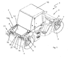
- Fig. 1 illustrates a designed as a road roller 1 self-propelled construction machine with a front end 2 and a rear end 3, which are connected to each other via a pendulum / articulated joint.
- a front drum 4 and the rear carriage 3 At the front of the car 2, a front drum 4 and the rear carriage 3, a rear drum 5 is arranged.
- the two bandages are mounted on vertical side supports 6, 7 on the front end 2 and rear end 3, which are held on frame-side horizontal supports 8 and 9 respectively.
- On the front of the car 2 is also a driver's cab 10th
- the upper side of the front carriage 2 has, between the driver's cab 10 and the front end 11 of the road roller 1, a large area of a panel 12 of the front carriage 4 sloping towards the front end 11 of the road roller 1.
- the cover 12 extends substantially over the entire width of the front carriage 2.
- the side is bounded by the carriers 8 and body parts 12a adjoining therein.
- the cladding 12 is a substantially planar surface. It can consist of a plastic or sheet metal part. Under the panel 12 or can, for example, tanks, drive means and the like. be arranged (not shown).
- the panel 12 terminates in front of the upper apex line of the front bandage 4.
- the front end 11 of the panel 12 is lower than the end of the panel 12, which connects to the cab 10.
- the panel 12 ends in front of the apex line of the front bandage 4.
- the panel 12 thus a sloping to the front slope of the top of the front end 2 is formed to the front bandage 4. This results in a downwardly widening good field of view for an operator from the driver's cab 10 to the upper region of the front drum 4 and the area lying in front of the road roller 1.
- a horizontal cross member 13 is arranged, which runs axially parallel to the front bandage 4 and above the front bandage 4.
- the traverse also extends above the low-lying front end of the top panel 12 and in front of the front end of the top panel 12 or bevel.
- a viewing window 30 is formed between the underside of the crossbar 13 and the front end of the panel 12, which is a free view of the operator between the crossbar 13 and the front end of the panel through and immediately above the crest line of the front bandage 4 on the front of Road roller 1 lying area allows.
- the traverse 13 connects with its two end faces to the carrier 8 and is fixed there. It bridges the area between the two supports 8 with a predetermined height distance D of the front bandage 4 and the front end of the upper-side panel 12, without communicating with the upper-side panel 12.
- the traverse 13 is a self-supporting hollow body 15 ( Fig. 2 ) formed of plastic whose walls form a closed outer surface.
- lighting devices are integrated, which are formed in the example shown as a headlight 16.
- the outer walls are broken only for the implementation of lines for the lighting equipment and, if necessary, to record screw.
- the wall of the hollow body 15 is shaped so that bulges, curves, beads and the like are formed, such as in a central region 31, which is formed as an arc, with which the flexural rigidity is increased.
- it has a front plane surface 14, on which, for example, passive lighting devices, such as reflectors, can be attached.
- the hollow body 15 As the front view and the top view of the hollow body 15 according to Fig. 2 and Fig. 3 show, he has two side portions 17, 18 for receiving the headlights 16.
- the headlights 16 are flush in the side areas 17, 18. Since the hollow body 15 is molded from plastic, it can be brought into a visually appealing shape.
- fastening elements 32 At the two ends of the hollow body 15 are fastening elements 32, here in the form of threaded openings, via which the hollow body 15 is screwed to the carriers 8.
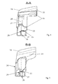
- the hollow body 15 is formed in the side regions 17, 18 as a hollow ring 19 in the manner of a torus having a front and rear open receiving space 20 for the headlights 16 (FIGS. not shown) surrounds.
- the wall of this hollow ring shape of the side portion 18 and the receiving space 20 is well stiffened so that it is sufficiently stable for supporting the headlights 16 and for attachment to the carriers 8, 9.
- the mounting of the headlights 16 is easy due to the access from the front and rear into the receiving space 20.
- a front cover 21 of the receiving space 20 is shown for the headlights 16, which is bolted to the hollow body 15 and the receiving space 20 closes forward.
- the hollow ring 19 is further formed so that it has a larger cross-section in its upper sector 22, as in its underlying sector 23.
- the receiving space 20 upwards a broader shield against external influences than down.
- the hollow body 15 has a middle part 24 which connects the opposite ring sectors of the hollow rings 19 in the side regions 17, 18 to one another.
- the hollow body 15 has on its underside over its entire length a hollow edge 29 with a horizontal leg and a downwardly directed vertical leg.
- a shoulder with a horizontal stop surface 25 and a vertical stop surface 26 are formed over the entire length of the hollow body 15.
- the two abutment surfaces form a semi-open receiving space for a metallic carrier strip 27, which extends horizontally between the carriers 8, 9.
Landscapes
- Engineering & Computer Science (AREA)
- Mechanical Engineering (AREA)
- Architecture (AREA)
- Civil Engineering (AREA)
- Structural Engineering (AREA)
- Road Paving Machines (AREA)
- Body Structure For Vehicles (AREA)
Abstract
Description
- Die Erfindung betrifft eine selbstfahrende Straßenbaumaschine, beispielsweise eine Straßenwalze, mit einer lichttechnischen Anlage an der Frontseite und/oder der Heckseite. Die Erfindung betrifft ferner eine als Straßenwalze ausgebildete Straßenbaumaschine mit einem Vorderwagen und einem Hinterwagen, die über ein Pendel-/Knickgelenk miteinander verbunden sind, wobei auf dem Vorderwagen oder dem Hinterwagen eine Fahrerkabine angeordnet ist, wobei der Vorderwagen zwei seitliche Tragelemente aufweist, an welchen zwei Stützen für die vordere Bandage angebracht sind, wobei der Vorderwagen ferner zwischen den beiden Tragelementen vor der Fahrerkabine zur Frontseite der Straßenwalze hin eine nach unten abfallende Abschrägung aufweist, und wobei zwischen den beiden Tragelementen und oberhalb der Abschrägung eine Traverse verläuft, an welcher lichttechnische Einrichtungen angeordnet sind.
- Bei bekannten selbstfahrenden Baumaschinen sind die lichttechnischen Anlagen in eine Fahrzeugverkleidung integriert, oder auf der Fahrzeugverkleidung oder auf Rahmenteilen des Fahrzeuges angeordnet. Zu den selbstfahrenden Baumaschinen gehören Straßenwalzen, die im Verkehrswegebau eingesetzt werden. Durch die Abschrägung des Vorderwagens soll dem Fahrzeugführer ein möglichst großer Sichtbereich auf den Untergrund vor der Straßenwalze freigegeben werden. Der in Vorwärtsfahrtrichtung liegende vordere Rand der Abschrägung liegt deshalb relativ tief, so dass die lichttechnischen Einrichtungen, wie zum Beispiel Scheinwerfer und Signalleuchten, auf einer Traverse oberhalb der Abschrägung und in einer vorgeschriebenen Höhe angeordnet sind.
- Aus
DE 102007040292 A1 ist bekannt, die Rückleuchten und das Kennzeichen eines Kraftfahrzeugs an einem Hohlkörper anzuordnen, der im Rotationsverfahren aus einem thermoplastischen Kunststoff hergestellt ist. - Der Erfindung liegt die Aufgabe zu Grunde, eine Straßenbaumaschine der eingangs angegebenen Art anzugeben, bei welcher die Montage, Wartung und Reparatur bezüglich der lichttechnischen Einrichtungen vereinfacht ist.
- Diese Aufgabe wird dadurch gelöst, dass die lichttechnischen Einrichtungen in einen selbstragenden Hohlkörper aus Kunststoff integriert sind. Für eine Straßenwalze der eingangs genannten Art wird die Aufgabe dadurch gelöst, dass die Traverse aus einem selbstragenden Hohlkörper aus Kunststoff besteht, in welchem die lichttechnischen Einrichtungen integriert sind.
- Zu den lichttechnischen Einrichtungen zählen an der Frontseite Fernlicht und Abblendlicht sowie Nebelscheinwerfer. Heckseitig gehören dazu Rückleuchten, Nebelschlussleuchten, Rückfahrscheinwerfer, Schlussleuchten und Bremsleuchten. Sowohl am Heck als auch an der Vorderseite handelt es sich um Fahrtrichtungsanzeiger, Kennzeichenbeleuchtung und selbstleuchtende Nummernschilder. Weiterhin gibt es passive lichttechnische Einrichtungen wie Reflektoren, die zum Beispiel in Form einer Konturmarkierung verwendet werden.
- Die Erfindung hat den Vorteil, dass der Hohlkörper und die lichttechnischen Einrichtungen als eine Einheit vormontiert werden können, so dass diese Einheit mit einfachen Mitteln und in kurzer Zeit an der Baumaschine verbaut werden kann. Es handelt sich erfindungsgemäß um ein Modul, dessen Einbau die Gesamtmontagezeit der Maschine verkürzt. Außerdem erlaubt die Ausführung aus Kunststoff vielfältige Möglichkeiten der optischen Gestaltung. Da der Hohlkörper eine gewisse Elastizität aufweist, ist die Gefahr von Beschädigungen, welche die Funktion der lichttechnischen Einrichtungen beeinträchtigt, geringer, weil Stöße u.ä. aufgefangen werden. Ist ein Austausch erforderlich, ist dies auf einfache Weise möglich.
- Es ist vorteilhaft, dass der Vorderwagen zwischen den beiden Trägern vor der Fahrerkabine zur Frontseite der Straßenwalze hin eine oberseitige, nach unten abfallende Verkleidung des Vorderwagens aufweist, und dass die Traverse von der Abschrägung beabstandet freitragend zwischen den beiden Trägern angeordnet ist, wobei zwischen der Verkleidung und der Traverse ein freies Sichtfenster gebildet wird. Dadurch ist einerseits das Sichtfeld des Walzenführers auf den Bereich unmittelbar vor der Straßenwalze nicht eingeschränkt, da zwischen der Abschrägung und der Traverse das freie Sichtfenster vorhanden ist. Andererseits befindet sich die Traverse mit den lichttechnischen Anlagen in einer Höhe, in welcher sie nicht mit eventuellen Hindernissen in Kontakt kommt, wie sie häufig auf Baustellen anzutreffen sind.
- Eine bevorzugte Weiterbildung der Erfindung besteht darin, dass der Hohlkörper aus einem faserverstärkten Kunststoff oder einem Verbundmaterial besteht, was die Tragfähigkeit und die Widerstandsfähigkeit gegen Beschädigungen erhöht.
- Die Herstellung des Hohlkörpers kann auf einfache Weise durch ein Schalengießverfahren erfolgen, bei welchem er aus einer Schmelze gebildet ist, die an einer Formwand der Gießform erstarrt ist. Mit diesem an sich bekannten Verfahren lässt sich die Formgestaltung des Hohlkörpers auf vielfältige Weise umsetzen.
- Es erweist sich ferner zum Schutz der lichttechnischen Einrichtungen gegen Umwelteinflüsse und Beschädigungen als vorteilhaft, dass der Hohlkörper Ausnehmungen zur Aufnahme von Scheinwerfern und/oder Signallampen aufweist.
- Es kann außerdem vorteilhaft sein, dass der Hohlraum mit Material zur Schwingungsdämpfung oder Aufballastierung gefüllt ist. Alternativ kann der Hohlkörper als Flüssigkeitstank für Wasser oder Treibstoff ausgebildet sein.
- Die Montage, Wartung und der Austausch des Hohlkörpers werden dadurch weiter vereinfacht, dass er integrierte elektrische Anschlusselemente für die lichttechnischen Einrichtungen, bevorzugt Steckverbinder, aufweist. Es sind somit zur Herstellung der elektrischen Verbindungen zwischen dem Hohlkörper und der übrigen Baumaschine keine speziellen Kenntnisse oder Werkzeuge erforderlich.
- Wenn der Hohlkörper einen größeren Abstand an der Baumaschine überbrücken soll, ist es zweckmäßig, dass die Traverse aus dem Hohlkörper und einer biegesteifen Verstrebung, insbesondere einer metallischen Strebe, gebildet ist. Bei einer Straßenwalze der eingangs genannten Art erweist sich eine derartige metallische Strebe zwischen den beiden Tragelementen und oberhalb der Abschrägung als vorteilhaft.
- Nachfolgend wird die Erfindung anhand eines in der Zeichnung dargestellten Ausführungsbeispiels weiter erläutert. Es zeigen schematisch:
- Fig. 1
- eine perspektivische Ansicht auf eine Straßenwalze;
- Fig. 2
- eine Frontansicht einer Traverse der Straßenwalze;
- Fig. 3
- eine Draufsicht auf die Traverse von
Fig. 2 ; - Fig. 4
- einen Querschnitt durch die Traverse von
Fig. 2 entlang der Schnittlinie A-A; und - Fig. 5
- einen Querschnitt durch die Traverse von
Fig. 3 entlang der Schnittlinie B-B. -
Fig. 1 veranschaulicht eine als Straßenwalze 1 ausgebildete selbstfahrende Baumaschine mit einem Vorderwagen 2 und einem Hinterwagen 3, die über ein Pendel-/Knickgelenk miteinander verbunden sind. Am Vorderwagen 2 ist eine vordere Bandage 4 und am Hinterwagen 3 eine hintere Bandage 5 angeordnet. Die beiden Bandagen sind über vertikale seitliche Stützen 6, 7 am Vorderwagen 2 bzw. Hinterwagen 3 gelagert, die an rahmenseitigen horizontalen Trägern 8 bzw. 9 gehalten sind. Auf dem Vorderwagen 2 befindet sich ferner eine Fahrerkabine 10. - Die Oberseite des Vorderwagens 2 weist zwischen der Fahrerkabine 10 und dem frontseitigen Ende 11 der Straßenwalze 1 großflächig eine zum frontseitigen Ende 11 der Straßenwalze 1 abfallende Verkleidung 12 des Vorderwagens 4 auf. Die Verkleidung 12 erstreckt sich im Wesentlichen über die gesamte Breite des Vorderwagens 2. Seitlich wird sie von den Trägern 8 und sich darin anschließenden Karosserieteilen 12a begrenzt. Bei der Verkleidung 12 handelt es sich um eine im Wesentlichen plane Fläche. Sie kann aus einem Kunststoff- oder Blechteil bestehen. Unter der Verkleidung 12 bzw. können zum Beispiel Tanks, Antriebsmittel u.ä. angeordnet sein (nicht dargestellt). Die Verkleidung 12 endet vor der oberen Scheitellinie der vorderen Bandage 4. Das frontseitige Ende 11 der Verkleidung 12 liegt tiefer als das Ende der Verkleidung 12, welches an die Fahrerkabine 10 anschließt. Die Verkleidung 12 endet vor der Scheitellinie der vorderen Bandage 4. Durch die Verkleidung 12 wird somit eine zur Frontseite abfallende Abschrägung der Oberseite des Vorderwagens 2 bis zur vorderen Bandage 4 geformt. Dadurch ergibt sich ein sich nach unten erweiterndes gutes Sichtfeld für eine Bedienperson von der Fahrerkabine 10 auf den oberen Bereich der vordere Bandage 4 und den vor der Straßenwalze 1 liegenden Bereich.
- Zwischen den beiden Trägern 8 ist eine horizontale Traverse 13 angeordnet, die achsparallel zur vorderen Bandage 4 sowie oberhalb der vorderen Bandage 4 verläuft. Die Traverse verläuft ferner oberhalb des tiefliegenden frontseitigen Endes der oberseitigen Verkleidung 12 und vor dem frontseitigen Ende der oberseitigen Verkleidung 12 bzw. Abschrägung. Dadurch wird zwischen der Unterseite der Traverse 13 und dem frontseitigen Ende der Verkleidung 12 ein Sichtfenster 30 gebildet, welches einen freien Blick der Bedienperson zwischen der Traverse 13 und dem frontseitigen Ende der Verkleidung hindurch und unmittelbar über die Scheitellinie der vorderen Bandage 4 auf den vor der Straßenwalze 1 liegenden Bereich ermöglicht.
- Die Traverse 13 schließt mit ihren beiden Stirnseiten an die Träger 8 an und ist dort befestigt. Sie überbrückt den Bereich zwischen den beiden Trägern 8 mit einem vorgegebenen Höhenabstand D von der vorderen Bandage 4 und dem frontseitigen Ende der oberseitigen Verkleidung 12, ohne mit der oberseitigen Verkleidung 12 in Verbindung zu stehen.
- Die Traverse 13 ist als selbsttragender Hohlkörper 15 (
Fig. 2 ) aus Kunststoff ausgebildet, dessen Wände eine geschlossene Außenfläche bilden. In den Hohlkörper 15 sind lichttechnische Einrichtungen integriert, die im dargestellten Beispiel als Frontscheinwerfer 16 ausgebildet sind. Die Außenwände sind lediglich zur Durchführung von Leitungen für die lichttechnischen Einrichtungen durchbrochen und um ggfs. Schraubverbindungen aufzunehmen. Die Wandung des Hohlkörpers 15 ist so geformt, dass Ausbauchungen, Rundungen, Wülste und ähnliches gebildet werden, wie beispielsweise in einem zentralen Bereich 31, der als Bogen geformt ist, mit welchem die Biegesteifigkeit erhöht wird. Außerdem weist sie eine frontseitige plane Fläche 14 auf, auf welcher beispielsweise passive lichttechnische Einrichtungen, wie Reflektoren, angebracht werden können. - Wie die Vorderansicht und die Draufsicht des Hohlkörpers 15 gemäß
Fig. 2 und Fig. 3 zeigen, weist er zwei Seitenbereiche 17, 18 zur Aufnahme der Frontscheinwerfer 16 auf. Die Frontscheinwerfer 16 liegen bündig in den Seitenbereichen 17, 18. Da der Hohlkörper 15 aus Kunststoff gegossen ist, kann er in eine optisch ansprechende Form gebracht werden. An den beiden Enden des Hohlkörpers 15 befinden sich Befestigungselemente 32, hier in Form von Gewindeöffnungen, über welche der Hohlkörper 15 an den Trägern 8 verschraubt wird. - Der in
Fig. 4 dargestellte Querschnitt durch den einen Seitenbereich 18 entspricht dem Querschnitt des anderen Seitenbereichs 17. Demnach ist der Hohlkörper 15 in den Seitenbereichen 17, 18 als Hohlring 19 in der Art eines Torus ausgeformt, der einen nach vorn und hinten offenen Aufnahmerum 20 für die Frontscheinwerfer 16 (nicht dargestellt) umgibt. Durch die Wandung dieser Hohlringform ist der Seitenbereich 18 und der Aufnahmeraum 20 gut ausgesteift, so dass er ausreichend stabil zum Tragen der Frontscheinwerfer 16 und zur Befestigung an den Trägern 8, 9 ist. Außerdem ist die Montage der Frontscheinwerfer 16 aufgrund des Zugangs von vorne und hinten in den Aufnahmeraum 20 einfach. In derFig. 4 ist eine frontseitige Abdeckscheibe 21 des Aufnahmeraums 20 für die Frontscheinwerfer 16 dargestellt, welche am Hohlkörper 15 verschraubt ist und den Aufnahmeraum 20 nach vorne abschließt. - Der Hohlring 19 ist ferner so ausgebildet, dass er in seinem oben liegenden Sektor 22 einen größeren Querschnitt hat, als in seinem unten liegenden Sektor 23. Dadurch weist der Aufnahmeraum 20 nach oben eine breitere Abschirmung gegen äußere Einflüsse auf als nach unten.
- Zwischen den beiden Seitenbereichen 17, 18 weist der Hohlkörper 15 einen Mittenteil 24 auf, der die gegenüberliegenden Ringsektoren der Hohlringe 19 in den Seitenbereichen 17, 18 miteinander verbindet.
-
Fig. 4 und Fig. 5 zeigen ferner, dass der Hohlkörper 15 an seiner Unterseite über seine gesamte Länge eine Hohlkante 29 mit einem horizontalen Schenkel und einem nach unten gerichteten vertikalen Schenkel hat. Auf diese Weise werden über die gesamte Länge des Hohlkörpers 15 eine Schulter mit einer horizontalen Anschlagfläche 25 und einer vertikalen Anschlagfläche 26 gebildet. Die beiden Anschlagflächen bilden einen halboffenen Aufnahmeraum für eine metallische Trägerleiste 27, die horizontal zwischen den Trägern 8, 9 verläuft. Mit der Hohlkante 29 ist der Hohlkörper 15 über seine ganze Länge formschlüssig auf die Trägerleiste 27 gesetzt und dort verschraubt. Der Hohlkörper 15 liegt mit den beiden Anschlagflächen 25, 26 auf und an der Trägerleiste 27, so dass er von unten und in seitlicher Richtung abgestützt wird.
Claims (11)
- Straßenbaumaschine, die als Straßenwalze (1) ausgebildet ist, mit einem Vorderwagen (2) und einem Hinterwagen (3), die über ein Pendel-/Knickgelenk miteinander verbunden sind, wobei auf dem Vorderwagen (2) oder auf dem Hinterwagen eine Fahrerkabine (10) angeordnet ist, wobei der Vorderwagen (2) zwei seitliche Träger (8) aufweist, an welchen zwei Stützen (6) für die vordere Bandage (4) angebracht sind, und wobei zwischen den beiden Trägern (8, 9) eine Traverse (13) verläuft, an welcher lichttechnische Einrichtungen angeordnet sind,
dadurch gekennzeichnet,
dass die Traverse (13) aus einem selbstragenden Hohlkörper (15) aus Kunststoff besteht, in welchem die lichttechnischen Einrichtungen integriert sind. - Straßenbaumaschine nach Anspruch 1 ,
dadurch gekennzeichnet,
dass der Vorderwagen (2) zwischen den beiden Trägern (8) vor der Fahrerkabine (10) zur Frontseite der Straßenwalze (1) hin eine oberseitige, nach unten abfallende Verkleidung (12) des Vorderwagens (2) aufweist, und dass die Traverse (13) von der Abschrägung (12) beabstandet freitragend zwischen den beiden Trägern (8) angeordnet ist, wobei zwischen der Verkleidung (12) und der Traverse (13) ein freies Sichtfenster (30) gebildet wird. - Straßenbaumaschine nach einem der vorhergehenden Ansprüche ,
dadurch gekennzeichnet,
dass der Hohlkörper (15) aus einem faserverstärkten Kunststoff besteht. - Straßenbaumaschine nach einem der vorhergehenden Ansprüche,
dadurch gekennzeichnet,
dass der Hohlkörper (15) durch ein Schalengießverfahren hergestellt ist, bei welchem der Hohlkörper (15) aus einer an einer Formwand erstarrten Schmelze gebildet ist. - Straßenbaumaschine nach einem der vorhergehenden Ansprüche,
dadurch gekennzeichnet,
dass der Hohlkörper (15) Ausnehmungen zur Aufnahme von Scheinwerfern und/oder Signallampen aufweist. - Straßenbaumaschine nach einem der vorhergehenden Ansprüche,
dadurch gekennzeichnet,
dass der Hohlkörper (15) mit Material zur Schwingungsdämpfung oder Aufballastierung gefüllt ist. - Straßenbaumaschine nach einem der vorhergehenden Ansprüche,
dadurch gekennzeichnet,
dass der Hohlkörper (15) als Flüssigkeitstank für Wasser oder Treibstoff ausgebildet ist. - Straßenbaumaschine nach einem der vorhergehenden Ansprüche,
dadurch gekennzeichnet,
dass der Hohlkörper (15) integrierte elektrische Anschlusselemente aufweist. - Straßenbaumaschine nach einem der vorhergehenden Ansprüche,
dadurch gekennzeichnet,
dass die Traverse (13) aus dem Hohlkörper (15) und einer metallischen Trägerleiste (27) gebildet ist, die zwischen den beiden Trägern (8, 9) angeordnet ist. - Selbstragender Hohlkörper (15) für lichttechnische Einrichtungen nach einem der vorhergehenden Ansprüche.
- Traverse (13) für eine Straßenwalze (1) nach einem der vorhergehenden Ansprüche.
Applications Claiming Priority (1)
| Application Number | Priority Date | Filing Date | Title |
|---|---|---|---|
| DE102012016035.6A DE102012016035A1 (de) | 2012-08-13 | 2012-08-13 | Strassenbaumaschine |
Publications (3)
| Publication Number | Publication Date |
|---|---|
| EP2698473A2 true EP2698473A2 (de) | 2014-02-19 |
| EP2698473A3 EP2698473A3 (de) | 2016-12-21 |
| EP2698473B1 EP2698473B1 (de) | 2019-07-03 |
Family
ID=48998396
Family Applications (1)
| Application Number | Title | Priority Date | Filing Date |
|---|---|---|---|
| EP13004039.7A Active EP2698473B1 (de) | 2012-08-13 | 2013-08-13 | Strassenbaumaschine |
Country Status (2)
| Country | Link |
|---|---|
| EP (1) | EP2698473B1 (de) |
| DE (1) | DE102012016035A1 (de) |
Cited By (3)
| Publication number | Priority date | Publication date | Assignee | Title |
|---|---|---|---|---|
| EP3258014A1 (de) * | 2016-06-13 | 2017-12-20 | BOMAG GmbH & Co. OHG | Gummiradwalze |
| CN111851210A (zh) * | 2019-04-25 | 2020-10-30 | 徐州维尔德科技发展有限公司 | 一种路面整修用的光面轮压路机 |
| EP3858670A1 (de) * | 2020-02-03 | 2021-08-04 | Joseph Vögele AG | Baumaschine mit beleuchtungsanordnung |
Citations (1)
| Publication number | Priority date | Publication date | Assignee | Title |
|---|---|---|---|---|
| DE102007040292A1 (de) | 2007-08-24 | 2009-02-26 | Liberco Systems Gmbh | Leuchteneinheit |
Family Cites Families (3)
| Publication number | Priority date | Publication date | Assignee | Title |
|---|---|---|---|---|
| DE2058718A1 (de) * | 1970-04-21 | 1971-11-11 | Bopparder Maschb Gmbh | Baumaschine,insbesondere Strassenwalze |
| AU2366000A (en) * | 1998-12-21 | 2000-07-12 | Magna International Of America, Inc. | Method and apparatus for blow molding large reinforced plastic parts |
| US6988305B1 (en) * | 1999-12-17 | 2006-01-24 | Magna International Of America, Inc. | Method and apparatus for blow molding large reinforced plastic parts |
-
2012
- 2012-08-13 DE DE102012016035.6A patent/DE102012016035A1/de not_active Withdrawn
-
2013
- 2013-08-13 EP EP13004039.7A patent/EP2698473B1/de active Active
Patent Citations (1)
| Publication number | Priority date | Publication date | Assignee | Title |
|---|---|---|---|---|
| DE102007040292A1 (de) | 2007-08-24 | 2009-02-26 | Liberco Systems Gmbh | Leuchteneinheit |
Cited By (5)
| Publication number | Priority date | Publication date | Assignee | Title |
|---|---|---|---|---|
| EP3258014A1 (de) * | 2016-06-13 | 2017-12-20 | BOMAG GmbH & Co. OHG | Gummiradwalze |
| US10309065B2 (en) | 2016-06-13 | 2019-06-04 | Bomag Gmbh | Rubber tire roller |
| CN111851210A (zh) * | 2019-04-25 | 2020-10-30 | 徐州维尔德科技发展有限公司 | 一种路面整修用的光面轮压路机 |
| EP3858670A1 (de) * | 2020-02-03 | 2021-08-04 | Joseph Vögele AG | Baumaschine mit beleuchtungsanordnung |
| US11692318B2 (en) | 2020-02-03 | 2023-07-04 | Joseph Voegele Ag | Construction machine with lighting arrangement |
Also Published As
| Publication number | Publication date |
|---|---|
| EP2698473B1 (de) | 2019-07-03 |
| DE102012016035A1 (de) | 2014-02-13 |
| EP2698473A3 (de) | 2016-12-21 |
Similar Documents
| Publication | Publication Date | Title |
|---|---|---|
| DE602005004913T2 (de) | Anordnung für eine fahrzeugseitenverkleidung und fahrzeug mit einer solchen seitenverkleidung | |
| EP1002700A2 (de) | Anordnung eines Frontschutzbügels an einem Kraftwagenbug | |
| DE2922893A1 (de) | Endeinheit, vorzugsweise bugpartie eines kraftfahrzeuges | |
| DE102009047833A1 (de) | Rückspiegelfuß | |
| DE102011081784A1 (de) | Energie absorbierende Windlaufstruktur | |
| EP1560730B1 (de) | Fahrzeug mit ladeboxen oder ladeflächen | |
| EP2698473B1 (de) | Strassenbaumaschine | |
| DE102014101449B4 (de) | Kabinenvorrichtung einer Arbeitsmaschine | |
| DE102005051662A1 (de) | Vorrichtung zum lagegenauen Befestigen eines Stossfängers | |
| DE102013006779A1 (de) | Fahrradträger | |
| DE102016007170A1 (de) | Gummiradwalze | |
| DE3151280C2 (de) | Fahrgestellrahmen für Fahrzeuge, insbesondere Omnibusse | |
| DE112017002920T5 (de) | Montagestruktur für einen aus Kunstharz hergestellten Kraftstofftank und Baumaschine | |
| WO2004071822A1 (de) | Frontendbereich | |
| DE9017550U1 (de) | Anfahrschutz für Lastkraftwagen, insbesondere Sattelauflieger von Sattelschleppern | |
| DE102014113565A1 (de) | Versteifungselement | |
| DE102018125261A1 (de) | Fahrzeugfrontstruktur | |
| DE202013002033U1 (de) | Frontpartie für ein Kraftfahrzeug | |
| EP3636919B1 (de) | Mobile dickstoffpumpe | |
| DE102017222321A1 (de) | Front-Stoßfängeranordnungsstützstruktur für ein Fahrzeug | |
| EP3415397B1 (de) | Schienenfahrzeug mit sicherheitsfahrerkabine | |
| EP1462308A2 (de) | Scheinwerfergehäuse mit einer integrierten Strukturstrebe | |
| DE112017002194B4 (de) | Kühlerträgerabdeckung für ein Fahrzeug | |
| DE19634103C2 (de) | Spritzwasserfänger für Fahrzeuge | |
| DE102019130002A1 (de) | Kennzeichenhalter |
Legal Events
| Date | Code | Title | Description |
|---|---|---|---|
| AK | Designated contracting states |
Kind code of ref document: A2 Designated state(s): AL AT BE BG CH CY CZ DE DK EE ES FI FR GB GR HR HU IE IS IT LI LT LU LV MC MK MT NL NO PL PT RO RS SE SI SK SM TR |
|
| AX | Request for extension of the european patent |
Extension state: BA ME |
|
| PUAI | Public reference made under article 153(3) epc to a published international application that has entered the european phase |
Free format text: ORIGINAL CODE: 0009012 |
|
| PUAL | Search report despatched |
Free format text: ORIGINAL CODE: 0009013 |
|
| RIC1 | Information provided on ipc code assigned before grant |
Ipc: E01C 19/23 20060101AFI20161108BHEP |
|
| AK | Designated contracting states |
Kind code of ref document: A3 Designated state(s): AL AT BE BG CH CY CZ DE DK EE ES FI FR GB GR HR HU IE IS IT LI LT LU LV MC MK MT NL NO PL PT RO RS SE SI SK SM TR |
|
| AX | Request for extension of the european patent |
Extension state: BA ME |
|
| STAA | Information on the status of an ep patent application or granted ep patent |
Free format text: STATUS: THE APPLICATION HAS BEEN PUBLISHED |
|
| STAA | Information on the status of an ep patent application or granted ep patent |
Free format text: STATUS: REQUEST FOR EXAMINATION WAS MADE |
|
| 17P | Request for examination filed |
Effective date: 20170901 |
|
| RBV | Designated contracting states (corrected) |
Designated state(s): AL AT BE BG CH CY CZ DE DK EE ES FI FR GB GR HR HU IE IS IT LI LT LU LV MC MK MT NL NO PL PT RO RS SE SI SK SM TR |
|
| STAA | Information on the status of an ep patent application or granted ep patent |
Free format text: STATUS: EXAMINATION IS IN PROGRESS |
|
| 17Q | First examination report despatched |
Effective date: 20180430 |
|
| GRAP | Despatch of communication of intention to grant a patent |
Free format text: ORIGINAL CODE: EPIDOSNIGR1 |
|
| STAA | Information on the status of an ep patent application or granted ep patent |
Free format text: STATUS: GRANT OF PATENT IS INTENDED |
|
| INTG | Intention to grant announced |
Effective date: 20190225 |
|
| GRAS | Grant fee paid |
Free format text: ORIGINAL CODE: EPIDOSNIGR3 |
|
| GRAA | (expected) grant |
Free format text: ORIGINAL CODE: 0009210 |
|
| STAA | Information on the status of an ep patent application or granted ep patent |
Free format text: STATUS: THE PATENT HAS BEEN GRANTED |
|
| AK | Designated contracting states |
Kind code of ref document: B1 Designated state(s): AL AT BE BG CH CY CZ DE DK EE ES FI FR GB GR HR HU IE IS IT LI LT LU LV MC MK MT NL NO PL PT RO RS SE SI SK SM TR |
|
| REG | Reference to a national code |
Ref country code: GB Ref legal event code: FG4D Free format text: NOT ENGLISH |
|
| REG | Reference to a national code |
Ref country code: CH Ref legal event code: EP Ref country code: AT Ref legal event code: REF Ref document number: 1151147 Country of ref document: AT Kind code of ref document: T Effective date: 20190715 |
|
| REG | Reference to a national code |
Ref country code: IE Ref legal event code: FG4D Free format text: LANGUAGE OF EP DOCUMENT: GERMAN |
|
| REG | Reference to a national code |
Ref country code: DE Ref legal event code: R096 Ref document number: 502013013078 Country of ref document: DE |
|
| REG | Reference to a national code |
Ref country code: CH Ref legal event code: NV Representative=s name: HEPP WENGER RYFFEL AG, CH |
|
| REG | Reference to a national code |
Ref country code: NL Ref legal event code: MP Effective date: 20190703 |
|
| REG | Reference to a national code |
Ref country code: LT Ref legal event code: MG4D |
|
| PG25 | Lapsed in a contracting state [announced via postgrant information from national office to epo] |
Ref country code: SE Free format text: LAPSE BECAUSE OF FAILURE TO SUBMIT A TRANSLATION OF THE DESCRIPTION OR TO PAY THE FEE WITHIN THE PRESCRIBED TIME-LIMIT Effective date: 20190703 Ref country code: BG Free format text: LAPSE BECAUSE OF FAILURE TO SUBMIT A TRANSLATION OF THE DESCRIPTION OR TO PAY THE FEE WITHIN THE PRESCRIBED TIME-LIMIT Effective date: 20191003 Ref country code: NL Free format text: LAPSE BECAUSE OF FAILURE TO SUBMIT A TRANSLATION OF THE DESCRIPTION OR TO PAY THE FEE WITHIN THE PRESCRIBED TIME-LIMIT Effective date: 20190703 Ref country code: PT Free format text: LAPSE BECAUSE OF FAILURE TO SUBMIT A TRANSLATION OF THE DESCRIPTION OR TO PAY THE FEE WITHIN THE PRESCRIBED TIME-LIMIT Effective date: 20191104 Ref country code: LT Free format text: LAPSE BECAUSE OF FAILURE TO SUBMIT A TRANSLATION OF THE DESCRIPTION OR TO PAY THE FEE WITHIN THE PRESCRIBED TIME-LIMIT Effective date: 20190703 Ref country code: HR Free format text: LAPSE BECAUSE OF FAILURE TO SUBMIT A TRANSLATION OF THE DESCRIPTION OR TO PAY THE FEE WITHIN THE PRESCRIBED TIME-LIMIT Effective date: 20190703 Ref country code: FI Free format text: LAPSE BECAUSE OF FAILURE TO SUBMIT A TRANSLATION OF THE DESCRIPTION OR TO PAY THE FEE WITHIN THE PRESCRIBED TIME-LIMIT Effective date: 20190703 Ref country code: NO Free format text: LAPSE BECAUSE OF FAILURE TO SUBMIT A TRANSLATION OF THE DESCRIPTION OR TO PAY THE FEE WITHIN THE PRESCRIBED TIME-LIMIT Effective date: 20191003 |
|
| PG25 | Lapsed in a contracting state [announced via postgrant information from national office to epo] |
Ref country code: LV Free format text: LAPSE BECAUSE OF FAILURE TO SUBMIT A TRANSLATION OF THE DESCRIPTION OR TO PAY THE FEE WITHIN THE PRESCRIBED TIME-LIMIT Effective date: 20190703 Ref country code: GR Free format text: LAPSE BECAUSE OF FAILURE TO SUBMIT A TRANSLATION OF THE DESCRIPTION OR TO PAY THE FEE WITHIN THE PRESCRIBED TIME-LIMIT Effective date: 20191004 Ref country code: ES Free format text: LAPSE BECAUSE OF FAILURE TO SUBMIT A TRANSLATION OF THE DESCRIPTION OR TO PAY THE FEE WITHIN THE PRESCRIBED TIME-LIMIT Effective date: 20190703 Ref country code: IS Free format text: LAPSE BECAUSE OF FAILURE TO SUBMIT A TRANSLATION OF THE DESCRIPTION OR TO PAY THE FEE WITHIN THE PRESCRIBED TIME-LIMIT Effective date: 20191103 Ref country code: RS Free format text: LAPSE BECAUSE OF FAILURE TO SUBMIT A TRANSLATION OF THE DESCRIPTION OR TO PAY THE FEE WITHIN THE PRESCRIBED TIME-LIMIT Effective date: 20190703 Ref country code: AL Free format text: LAPSE BECAUSE OF FAILURE TO SUBMIT A TRANSLATION OF THE DESCRIPTION OR TO PAY THE FEE WITHIN THE PRESCRIBED TIME-LIMIT Effective date: 20190703 |
|
| PG25 | Lapsed in a contracting state [announced via postgrant information from national office to epo] |
Ref country code: TR Free format text: LAPSE BECAUSE OF FAILURE TO SUBMIT A TRANSLATION OF THE DESCRIPTION OR TO PAY THE FEE WITHIN THE PRESCRIBED TIME-LIMIT Effective date: 20190703 |
|
| PG25 | Lapsed in a contracting state [announced via postgrant information from national office to epo] |
Ref country code: DK Free format text: LAPSE BECAUSE OF FAILURE TO SUBMIT A TRANSLATION OF THE DESCRIPTION OR TO PAY THE FEE WITHIN THE PRESCRIBED TIME-LIMIT Effective date: 20190703 Ref country code: IT Free format text: LAPSE BECAUSE OF FAILURE TO SUBMIT A TRANSLATION OF THE DESCRIPTION OR TO PAY THE FEE WITHIN THE PRESCRIBED TIME-LIMIT Effective date: 20190703 Ref country code: RO Free format text: LAPSE BECAUSE OF FAILURE TO SUBMIT A TRANSLATION OF THE DESCRIPTION OR TO PAY THE FEE WITHIN THE PRESCRIBED TIME-LIMIT Effective date: 20190703 Ref country code: EE Free format text: LAPSE BECAUSE OF FAILURE TO SUBMIT A TRANSLATION OF THE DESCRIPTION OR TO PAY THE FEE WITHIN THE PRESCRIBED TIME-LIMIT Effective date: 20190703 Ref country code: PL Free format text: LAPSE BECAUSE OF FAILURE TO SUBMIT A TRANSLATION OF THE DESCRIPTION OR TO PAY THE FEE WITHIN THE PRESCRIBED TIME-LIMIT Effective date: 20190703 |
|
| PG25 | Lapsed in a contracting state [announced via postgrant information from national office to epo] |
Ref country code: MC Free format text: LAPSE BECAUSE OF FAILURE TO SUBMIT A TRANSLATION OF THE DESCRIPTION OR TO PAY THE FEE WITHIN THE PRESCRIBED TIME-LIMIT Effective date: 20190703 Ref country code: SK Free format text: LAPSE BECAUSE OF FAILURE TO SUBMIT A TRANSLATION OF THE DESCRIPTION OR TO PAY THE FEE WITHIN THE PRESCRIBED TIME-LIMIT Effective date: 20190703 Ref country code: SM Free format text: LAPSE BECAUSE OF FAILURE TO SUBMIT A TRANSLATION OF THE DESCRIPTION OR TO PAY THE FEE WITHIN THE PRESCRIBED TIME-LIMIT Effective date: 20190703 Ref country code: IS Free format text: LAPSE BECAUSE OF FAILURE TO SUBMIT A TRANSLATION OF THE DESCRIPTION OR TO PAY THE FEE WITHIN THE PRESCRIBED TIME-LIMIT Effective date: 20200224 Ref country code: LU Free format text: LAPSE BECAUSE OF NON-PAYMENT OF DUE FEES Effective date: 20190813 |
|
| REG | Reference to a national code |
Ref country code: BE Ref legal event code: MM Effective date: 20190831 |
|
| REG | Reference to a national code |
Ref country code: DE Ref legal event code: R097 Ref document number: 502013013078 Country of ref document: DE |
|
| PLBE | No opposition filed within time limit |
Free format text: ORIGINAL CODE: 0009261 |
|
| STAA | Information on the status of an ep patent application or granted ep patent |
Free format text: STATUS: NO OPPOSITION FILED WITHIN TIME LIMIT |
|
| PG2D | Information on lapse in contracting state deleted |
Ref country code: IS |
|
| PG25 | Lapsed in a contracting state [announced via postgrant information from national office to epo] |
Ref country code: FR Free format text: LAPSE BECAUSE OF NON-PAYMENT OF DUE FEES Effective date: 20190903 Ref country code: IE Free format text: LAPSE BECAUSE OF NON-PAYMENT OF DUE FEES Effective date: 20190813 |
|
| 26N | No opposition filed |
Effective date: 20200603 |
|
| PG25 | Lapsed in a contracting state [announced via postgrant information from national office to epo] |
Ref country code: BE Free format text: LAPSE BECAUSE OF NON-PAYMENT OF DUE FEES Effective date: 20190831 Ref country code: SI Free format text: LAPSE BECAUSE OF FAILURE TO SUBMIT A TRANSLATION OF THE DESCRIPTION OR TO PAY THE FEE WITHIN THE PRESCRIBED TIME-LIMIT Effective date: 20190703 |
|
| GBPC | Gb: european patent ceased through non-payment of renewal fee |
Effective date: 20191003 |
|
| REG | Reference to a national code |
Ref country code: AT Ref legal event code: MM01 Ref document number: 1151147 Country of ref document: AT Kind code of ref document: T Effective date: 20190813 |
|
| PG25 | Lapsed in a contracting state [announced via postgrant information from national office to epo] |
Ref country code: GB Free format text: LAPSE BECAUSE OF NON-PAYMENT OF DUE FEES Effective date: 20191003 |
|
| PG25 | Lapsed in a contracting state [announced via postgrant information from national office to epo] |
Ref country code: AT Free format text: LAPSE BECAUSE OF NON-PAYMENT OF DUE FEES Effective date: 20190813 |
|
| PG25 | Lapsed in a contracting state [announced via postgrant information from national office to epo] |
Ref country code: CY Free format text: LAPSE BECAUSE OF FAILURE TO SUBMIT A TRANSLATION OF THE DESCRIPTION OR TO PAY THE FEE WITHIN THE PRESCRIBED TIME-LIMIT Effective date: 20190703 |
|
| PG25 | Lapsed in a contracting state [announced via postgrant information from national office to epo] |
Ref country code: HU Free format text: LAPSE BECAUSE OF FAILURE TO SUBMIT A TRANSLATION OF THE DESCRIPTION OR TO PAY THE FEE WITHIN THE PRESCRIBED TIME-LIMIT; INVALID AB INITIO Effective date: 20130813 Ref country code: MT Free format text: LAPSE BECAUSE OF FAILURE TO SUBMIT A TRANSLATION OF THE DESCRIPTION OR TO PAY THE FEE WITHIN THE PRESCRIBED TIME-LIMIT Effective date: 20190703 |
|
| PG25 | Lapsed in a contracting state [announced via postgrant information from national office to epo] |
Ref country code: MK Free format text: LAPSE BECAUSE OF FAILURE TO SUBMIT A TRANSLATION OF THE DESCRIPTION OR TO PAY THE FEE WITHIN THE PRESCRIBED TIME-LIMIT Effective date: 20190703 |
|
| P01 | Opt-out of the competence of the unified patent court (upc) registered |
Effective date: 20230527 |
|
| REG | Reference to a national code |
Ref country code: DE Ref legal event code: R082 Ref document number: 502013013078 Country of ref document: DE Representative=s name: ZIMMERMANN & PARTNER PATENTANWAELTE MBB, DE |
|
| PGFP | Annual fee paid to national office [announced via postgrant information from national office to epo] |
Ref country code: DE Payment date: 20250819 Year of fee payment: 13 |
|
| PGFP | Annual fee paid to national office [announced via postgrant information from national office to epo] |
Ref country code: CH Payment date: 20250901 Year of fee payment: 13 |
|
| PGFP | Annual fee paid to national office [announced via postgrant information from national office to epo] |
Ref country code: CZ Payment date: 20250801 Year of fee payment: 13 |