EP2698469A2 - Einstelleinrichtung eines Haushaltsgerätes sowie Bügeleisen - Google Patents
Einstelleinrichtung eines Haushaltsgerätes sowie Bügeleisen Download PDFInfo
- Publication number
- EP2698469A2 EP2698469A2 EP13179274.9A EP13179274A EP2698469A2 EP 2698469 A2 EP2698469 A2 EP 2698469A2 EP 13179274 A EP13179274 A EP 13179274A EP 2698469 A2 EP2698469 A2 EP 2698469A2
- Authority
- EP
- European Patent Office
- Prior art keywords
- housing
- rotary handle
- radial guide
- section
- electronics
- Prior art date
- Legal status (The legal status is an assumption and is not a legal conclusion. Google has not performed a legal analysis and makes no representation as to the accuracy of the status listed.)
- Granted
Links
Images


Classifications
-
- D—TEXTILES; PAPER
- D06—TREATMENT OF TEXTILES OR THE LIKE; LAUNDERING; FLEXIBLE MATERIALS NOT OTHERWISE PROVIDED FOR
- D06F—LAUNDERING, DRYING, IRONING, PRESSING OR FOLDING TEXTILE ARTICLES
- D06F75/00—Hand irons
- D06F75/08—Hand irons internally heated by electricity
- D06F75/26—Temperature control or indicating arrangements
- D06F75/265—Temperature indicating arrangements; Control knobs
-
- G—PHYSICS
- G05—CONTROLLING; REGULATING
- G05G—CONTROL DEVICES OR SYSTEMS INSOFAR AS CHARACTERISED BY MECHANICAL FEATURES ONLY
- G05G1/00—Controlling members, e.g. knobs or handles; Assemblies or arrangements thereof; Indicating position of controlling members
- G05G1/08—Controlling members for hand actuation by rotary movement, e.g. hand wheels
- G05G1/10—Details, e.g. of discs, knobs, wheels or handles
Definitions
- the invention relates to a device for setting an operating state of a household appliance according to the preamble of patent claim 1 and an iron, wherein the device is a fixed to a device section housing in which an electronics of the household appliance is arranged, a rotary handle for driving the electronics, the one on a rotary axis mounted carrier which is in operative engagement with the electronics, and wherein the rotary handle has at least one transparent wall portion, and wherein the device has at least one optical display element for displaying an operating state of the household appliance, which is covered by the rotary handle and with the the transparent wall section can be brought into overlap.
- the object of the invention is to provide a device for setting an operating state of a household appliance, which allows a stable and smooth running a rotary handle of the device. Furthermore, it is an object of the invention to provide an iron with a robust means for setting an operating condition.
- the rotary handle is a hollow ring profile, which is guided on a concentric to the axis of rotation radial guide of the housing and has an oriented in the direction of the axis of rotation arm from which extends the driver.
- the execution of the rotary handle as a hollow ring profile with an inner peripheral and / or outer peripheral radial guide allows high stability and leadership leadership smooth, as radial movements of the rotary handle are taken in an operation of the radial guide. Movements are thus not introduced into the electronics, but absorbed by the radial guide.
- the electronics thus assumes no mechanical management tasks of the rotary handle.
- such an adjustment can manufacture easily manufactured, assemble and install the household appliance. The adjustment can be easily connected after their preparation with a device housing.
- the electronics can be adapted to the respective domestic appliance, so that the adjusting device can be used in a large number of different household appliances.
- An axial guidance of the rotary handle can be improved if the rotary handle has an annular surface for support on an annular sliding surface of the device section. As a result, the rotary handle is not supported on the housing, so that no axial forces are introduced into the housing by an actuation of the rotary handle. Connections, by means of which the housing is connected in the installed state to the device section, are thus not burdened upon actuation of the rotary handle.
- the radial guide may be formed by a cylindrical portion of the housing and by an annular shoulder with which the rotary handle releasably locked.
- the rotary handle is guided on the inside circumference of the radial guide, whereby on the one hand, the radial guide is compact executable.
- the rotary handles three at the same circumferential angle spaced locking arms for releasable locking with the annular shoulder.
- the cylinder section may be closed on the head side.
- the cylinder portion may have a central opening through which the driver, which is designed as a pin, for example, is guided.
- the driver which is designed as a pin, for example.
- the arm may be in rotational motion in abutment with a body portion projecting from the cylinder portion.
- a cover for covering the radial guide may be provided.
- the cover releasably locked to the body acting as a rotation limiting body portion.
- the cover is supported with an annular surface on a radially inner support surface of the rotary handle.
- the cover is supported on the rotary handle, whereby a force acting on the cover in the axial direction force due to, for example, improper operation or actuation of the rotary handle is not introduced into the housing and thus in the connections of the housing to the device section, but directly into the device section becomes.
- electrical contact elements for connecting the electronics are arranged, for example, with a power supply in a housing section remote from the radial guide. This results in a spatial separation of the rotary handle of the contact elements, so that the contact elements both to each other or can be optimally arranged with each other and for connection with, for example, the power supply.
- the device is arranged with its radial guide in the region of a device opening and with their electrical contact elements within the household appliance.
- the housing sections positioned inside the household appliance are preferably watertight.
- An inventive iron has an adjusting device according to the invention, wherein the adjusting device is arranged with its electrical contact elements within the iron housing and with its radial guide outside of the iron housing.
- Such an iron has a robust adjustment with a precisely adjustable and smooth turning handle.
- the invention is particularly suitable for providing an iron with a robust adjustment for setting an operating condition with a precisely adjustable and smooth turning handle, which is also easy to assemble and disassemble.
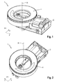
- FIG. 1 and 2 has a preferred device 1 for setting an operating state of a household appliance such as an iron a housing 2 and a rotary ring 4, which is rotatably mounted on the housing 2 about a in the vertical direction z extending axis of rotation or axis of rotation R.
- the setting device 1 is for example a temperature controller and allows the setting of various temperatures of the iron.
- the iron is preferably a steam iron.
- the housing 2 is a cuboid flat hollow body with a greater extent in the longitudinal direction x than in the transverse direction y. It consists of a plastic material and is transparent or translucent. It has a lower shell 6 and a detachably connected to this upper shell 8. The lower shell 6 and the upper shell 8 define an inner space 10 and are connected via snap fasteners 12 watertight to each other.
- a device electronics 14 is arranged, for example, a circuit board 16, optical display elements 18 such as LEDs for displaying a respective operating state and electrical contact elements 20 for connecting the board 16 with, for example Power supply of the iron has.
- the device electronics 14 includes an electronic element such as a potentiometer 21 for setting a desired temperature.
- the potentiometer 21 is preferably an electronic potentiometer, but may also be a mechanical potentiometer.
- the housing 2 has in longitudinal direction x or viewed from a sole tip of the iron from a front portion in which a radial guide 22 for guiding the rotary ring 4 and at least one protuberance-like chamber 24 for receiving one of the display elements 18 is arranged.
- the radial guide 22 has a cylinder section 26 extending from the upper shell 8 of the housing 2 in the vertical direction z and a circular disk 28 which closes the cylinder section 26 at its free head end.
- the cylinder section 26 and the circular disk 28 are arranged coaxially or concentrically with the axis of rotation R.
- the circular disk 28 is an integral part of the housing 2 and thus also transparent. In particular, it serves to form an annular shoulder 30.
- the circular disc 28 has a concentric with the axis of rotation R opening 34. Further, the circular disc 28 has a parallel to the rotation axis R in the vertical direction z extending tubular body portion 36 which surrounds a circular disc opening 37 and a radially inner collar 38 for releasably locking with a in FIG. 8 shown cover 40 has.
- the housing 4, as in FIG. 3 shown a rear area, which is remote from the front area.
- the rear region has two shell-side chambers 42, 44, which are opposite to one another on the upper shell side and viewed in the transverse direction y of the housing 2, for receiving one of the optical display elements 18.
- the rear region has a gap-like or slot-like opening 46 for the passage of the electrical contact elements 20, which is arranged on the upper shell side between the chambers 42, 44.
- the opening 46 is sealed watertight after the passage of the electrical contact elements 20.
- the opening 46 with a lid, a Seal insert, injected plastic material and the like may be closed.
- the housing 2 is positively connected to a device portion of a device housing 48 of the household appliance.
- it is positioned on the device section such that it is arranged with its rear region and thus the area accommodating the electrical contact elements 20 within the device housing 48 and with its front region and thus with the region accommodating the rotary ring 4 in a device opening 50.
- the rotary ring 4 is, as in the FIGS. 6 and 7 shown, a hollow ring body which is open on the bottom side and thus with a, the housing 2 facing bottom. He has in addition to the driver 32 in particular an inner circumferential wall 52, an outer peripheral wall 54 and an end wall 56.
- the rotary ring 4 is made of an opaque plastic material, but has at least one transparent wall portion 58 in the region of its end wall 56.
- the inner circumferential wall 52 is shortened with respect to the outer circumferential wall 54 in the vertical direction z. It is subdivided into individual circumferential sections by latching arms 60, 62, which extend from the end wall 56 in the direction of the axis of rotation R and are equally spaced in the circumferential direction. In the embodiment shown, three locking arms 60, 62 are provided, of which in the FIGS. 6 and 7 However, due to the perspective, only two latching arms 60, 62 are visible. Of course, less or more than two latching arms 60, 62 are possible.
- the latching arms 60, 62 are extended relative to the inner circumferential wall 52 and each have a radially inwardly facing hook portion 64 for releasable locking with the annular shoulder 30. To form a radially inner end-side and ring-like support surface 68, the inner peripheral wall 52 and its peripheral portions and the latching arms 60, 62 offset relative to the end wall 56 radially inwardly.
- the outer circumferential wall 54 has a bottom-side annular surface 70, by means of which the rotary ring 4 is guided in the mounted state on a device housing-side sliding surface 72.
- the sliding surface 72 is, as in the FIGS. 4 and 5 Shown is a shoulder surface of a ring-like web which extends from an inner wall 74 of the housing opening 50 radially inwardly and is an axial sliding bearing for the rotary ring 4. to simple handling or actuation of the rotary ring 4, the outer wall 54 may be provided with a ribbing 73.
- the end wall 56 is in the assembled state facing a user. As in FIG. 7 is shown, the end wall 56 is arranged in the mounted state of the rotary ring 4 on the front chamber 24. The end wall 56 thus covers the display element 18 in the vertical direction z and the peripheral walls 52, 54 cover the front chamber 24 in the longitudinal direction x and in the transverse direction y.
- the wall portion 58 can be brought into overlap or overlap with the display element 18, whereby due to the transparency of the chamber 24 and the wall portion 58, the user recognizes whether the display element 18 lights and thus the display element 18 associated Operating condition of the iron is reached.
- the driver 32 is arranged on the end of a radially inwardly extending from the inner peripheral wall 52 arm 76. It is formed like a pin and extends coaxially to the rotation axis R. In the assembled state, it dips through the opening 34 of the circular disk 28 and is thus in operative connection with the potentiometer 21 located in the cylinder section 26 as shown in the figures below the circular disk 28.
- the arm 76 extends from one of the peripheral portions of the inner circumferential wall 52. As in FIG FIG. 7 shown, it is at such a small axial distance or distance in the vertical direction z from the circular disk 28 spaced that it runs on a rotation of the rotary ring 4 laterally on the extending from the circular disk 28 body portion 36. As a result, a rotational limit acting in both directions of rotation is formed, thus preventing over-rotation of the potentiometer 21.
- the driver 32 dips into the FIGS. 4 and 5 shown potentiometer-side sleeve-like element 78 a.
- a display element 18 for indicating a further operating state of the iron.
- the cover 40 is, as in the FIGS. 8 . 9 and 10 shown, a circular plate-like body having a bottom 82 and a user-facing visible side 84. It consists of a plastic material and is transparent or by the display element 18 transilluminable. It has two mutually orthogonal extending from the bottom 82 opposite latching projections 86, 88, each having a facing away from the opposite latching projection 86, 88 hook portion 90.
- the latching projections 86, 88 are used for releasable latching with the housing 2.
- the cover 40 dips with its locking projections 86, 88 in the body portion 36 of the circular disc 28 and releasably engaged with the collar 38.
- the cover 40 is rotatably mounted on the housing 2.
- the cover 40 has an annular web 92 extending from its underside 82, which is raised or extended in the axial direction in the region of the latching projections 86, 88.
- the annular web 92 is encompassed by the annular surface 66, wherein it is arranged radially inwardly of the annular surface 66 such that in the mounted state, the cover 40 with the annular surface 66 rests flat on the support surface 68 of the rotary ring 4.
- the housing 2 is connected from the inside to the device section of the device housing 48 with the radial guide 22 positioned in the housing opening 50.
- the connection preferably takes place in a form-fitting manner.
- the electrical contact elements 20 are thus arranged within the device housing 48.
- the display elements 18 are arranged in the rear chambers 42, 44 within the device housing 48, so that the device housing 48, at least in the position range of the chambers 42, 44 is transparent.
- the rotary ring 4 is positioned in the direction of the rotation axis R from the outside in the housing opening 50 on the radial guide 22.
- the driver 32 is inserted through the opening 34 in the sleeve-like element 78 of the potentiometer 21 and the rotary ring 4 by means of the latching arms 60, 62 with the radial shoulder 30 releasably locked.
- the rotary ring 4 is now rotatably guided on the housing 2, wherein it is guided in the radial direction on the inner circumference side by the contact of the latching arms 60, 62 on the circular disc 28 of the radial guide 22 and in the axial direction by the support of its outer peripheral side annular surface 70 on the housing side sliding surface 72 is.
- a maximum rotation or a maximum angle of rotation is limited by an emergence of the arm 76 on a of the circular disc 28 extending body portion 36.
- the cover 40 is inserted with its locking projections 86, 88 in the body portion 36, which then releasably engage with the collar 38.
- the cover 40 is now rotatably mounted on the housing 2, wherein it is supported axially with its annular surface 66 on the support surface 68 of the rotary ring 4 and thus on the device housing 48.
- the number of display elements 18 and their arrangement is arbitrary. It is crucial that in each case is recognized by the user, whether they are energized or are lit or not energized and thus not lit.
- the display elements 18 may be colored per se.
- the display elements 18 receiving transparent housing sections 24, 42, 44, the display elements 18 concealing device housing sections and / or the rotary ring sections 58 may be colored.
- a display element 18 which lights up when a desired temperature is reached and thus signals to the user that the iron is ready for operation (eg green lighting).
- a display element 18 may be provided to indicate to the user that the target temperature has been exceeded (eg, red lighting).
- a display element 18 may be provided, for example, to signal the user that the desired temperature has not yet been reached (for example, orange lighting).
- a display element 18 may be provided to indicate to the user that an automatic shutdown feature is activated (eg, white lighting).
- a device for setting an operating state of a household appliance with a fixable on a device section housing in which electronics of the household appliance is arranged, a rotary handle for driving the electronics, which has a mounted on a rotary axis driver, which is in operative engagement with the Is located, and wherein the rotary handle has at least one transparent wall portion, and with at least one optical display element for displaying an operating state of the household appliance, which is covered by the rotary handle and with which the transparent wall portion is overlapped, wherein the rotary handle is a hollow ring profile, which is guided on a concentric with the axis of rotation radial guide of the housing and has an oriented in the direction of the axis of rotation arm from which extends the driver, and a Iron with such an adjustment, wherein the adjustment is arranged with their electrical contact elements within the iron housing and with its radial guidance outside of the iron housing.
Landscapes
- Engineering & Computer Science (AREA)
- Textile Engineering (AREA)
- Physics & Mathematics (AREA)
- General Physics & Mathematics (AREA)
- Automation & Control Theory (AREA)
- Switches With Compound Operations (AREA)
- Transmission Devices (AREA)
- Mechanical Control Devices (AREA)
Abstract
Description
- Die Erfindung betrifft eine Einrichtung zum Einstellen eines Betriebszustandes eines Haushaltsgerätes nach dem Oberbegriff des Patentanspruchs 1 sowie ein Bügeleisen, wobei die Einrichtung ein an einem Geräteabschnitt fixierbares Gehäuse, in dem eine Elektronik des Haushaltsgerätes angeordnet ist, einen Drehgriff zum Ansteuern der Elektronik, der einen auf einer Drehachse gelagerten Mitnehmer hat, der sich im Wirkeingriff mit der Elektronik befindet, und wobei der Drehgriff zumindest einen transparenten Wandungsabschnitt aufweist, und wobei die Einrichtung zumindest ein optisches Anzeigenelement zum Anzeigen eines Betriebszustandes des Haushaltsgerätes hat, das von dem Drehgriff verdeckt ist und mit dem der transparente Wandungsabschnitt in Überlappung bringbar ist.
- Eine derartige Einstelleinrichtung ist zum Beispiel in der deutschen Patentanmeldung
DE 38 04 369 A1 gezeigt. Nachteilig an diesem elektronischen Temperaturdrehknopfregler für ein Bügeleisen ist, dass sowohl eine axiale als auch eine radiale Führung des Drehgriffes über das den Mitnehmer aufnehmende Elektronikelement, insbesondere ein Potenziometer, erfolgt. Die radialen und axialen Bewegungen des Drehgriffes werden somit unmittelbar in das Potentiometer eingeleitet, wodurch die Gefahr besteht, dass dieses beschädigt wird. - Aufgabe der Erfindung ist es, eine Einrichtung zum Einstellen eines Betriebszustandes eines Haushaltsgerätes zu schaffen, das eine stabile und leichtgängige Führung eines Drehgriffes der Einrichtung ermöglicht. Des Weiteren ist es Aufgabe der Erfindung, ein Bügeleisen mit einer robusten Einrichtung zum Einstellen eines Betriebszustandes zu schaffen.
- Diese Aufgabe wird gelöst durch eine Einrichtung zum Einstellen eines Betriebszustandes eines Haushaltgerätes mit den Merkmalen des Patentanspruchs 1 und durch ein Bügeleisen mit den Merkmalen des Patentanspruchs 10. Vorteilhafte Aus- und Weiterbildungen, welche einzeln oder in Kombination miteinander einsetzbar sind, sind Gegenstand der jeweils abhängigen Ansprüche.
- Eine erfindungsgemäße Einrichtung zum Einstellen eines Betriebszustandes eines Haushaltsgerätes weist ein an einem Geräteabschnitt fixierbares Gehäuse, in dem eine Elektronik des Haushaltsgerätes angeordnet ist, einen Drehgriff zum Ansteuern der Elektronik, der einen auf einer Drehachse gelagerten Mitnehmer hat, der sich im Wirkeingriff mit der Elektronik befindet, und wobei der Drehgriff zumindest einen transparenten Wandungsabschnitt hat, und zumindest ein optisches Anzeigenelement zum Anzeigen eines Betriebszustandes des Haushaltsgerätes auf, das von dem Drehgriff verdeckt ist und mit dem der transparente Wandungsabschnitt in Überlappung bringbar ist. Erfindungsgemäß ist der Drehgriff ein Hohlringprofil, das an einer zur Drehachse konzentrischen Radialführung des Gehäuses geführt ist und einen in Richtung der Drehachse orientierten Arm hat, von dem sich der Mitnehmer erstreckt.
- Die Ausführung des Drehgriffs als ein Hohlringprofil mit einer innenumfangsseitigen und/oder außenumfangsseitigen Radialführung ermöglicht eine hohe Führungsstabilität und eine leichtgängige Führung, da radiale Bewegungen des Drehgriffes bei einer Betätigung von der Radialführung aufgenommen werden. Bewegungen werden somit nicht in die Elektronik eingeleitet, sondern von der Radialführung aufgenommen. Die Elektronik übernimmt somit keine mechanischen Führungsaufgaben des Drehgriffs. Zudem lässt sich eine derartige Einstelleinrichtung fertigungstechnisch einfach herstellen, montieren und am Haushaltsgerät installieren. Die Einstelleinrichtung kann nach ihrer Herstellung bequem mit einem Gerätegehäuse verbunden werden. Insbesondere kann die Elektronik an das jeweilige Haushaltsgerät angepasst werden, so dass die Einstelleinrichtung bei einer Vielzahl von verschiedenen Haushaltsgeräten verwendbar ist.
- Eine axiale Führung des Drehgriffes lässt sich verbessern, wenn der Drehgriff eine Ringfläche zur Abstützung an einer ringartigen Gleitfläche des Geräteabschnittes hat. Hierdurch stützt sich der Drehgriff nicht auf dem Gehäuse ab, so dass durch eine Betätigung des Drehgriffes keine axialen Kräfte in das Gehäuse eingeleitet werden. Verbindungen, mittels denen das Gehäuse im installierten Zustand an dem Geräteabschnitt angebunden ist, werden somit bei einer Betätigung des Drehgriffes nicht belastet.
- Die Radialführung kann von einem Zylinderabschnitt des Gehäuses und von einer Ringschulter gebildet sein, mit der der Drehgriff lösbar verrastet. Bevorzugterweise ist der Drehgriff innenumfangsseitig an der Radialführung geführt, wodurch zum einen die Radialführung kompakt ausführbar ist. Zum anderen kann bei der bevorzugten innenumfangsseitigen Führung der Drehgriff bequem am Außenumfang gegriffen und somit betätigt werden. Vorzugsweise weist der Drehgriffe drei im gleichen Umfangswinkel voneinander beabstandete Rastarme zur lösbaren Verrastung mit der Ringschulter auf.
- Zur Vermeidung einer versehentlichen Beschädigung oder Verschmutzung der Elektronik kann der Zylinderabschnitt kopfseitig verschlossen sein. Zur Herstellung einer Wirkverbindung des Mitnehmers mit der Elektronik kann der Zylinderabschnitt eine zentrale Öffnung aufweisen, durch die der beispielsweise als Zapfen ausgebildete Mitnehmer geführt ist. Eine derartige Variante ist fertigungstechnisch einfach auszuführen und einfach zu montierenden.
- Zur Schaffung einer Drehbegrenzung und somit zur Verhinderung eines Übersteuern der Elektronik kann der Arm bei einer Drehbewegung in Anlage mit einem von dem Zylinderabschnitt vorspringenden Körperabschnitt sein.
- Um eine Verschmutzung der Radialführung zu verhindern, kann eine Abdeckung zum Abdecken der Radialführung vorgesehen sein. Vorzugsweise verrastet die Abdeckung lösbar mit dem als Drehbegrenzung wirkenden Körperabschnitt.
- Bevorzugterweise stützt sich die Abdeckung mit einer Ringfläche auf einer radial inneren Stütztfläche des Drehgriffs ab. Hierdurch ist die Abdeckung auf den Drehgriff abgestützt, wodurch eine auf die Abdeckung in axialer Richtung wirkende Kraft infolge einer beispielsweise unsachgemäßen Bedienung bzw. Betätigung des Drehgriffs nicht in das Gehäuse und somit in die Verbindungen des Gehäuses an dem Geräteabschnitt, sondern direkt in den Geräteabschnitt eingeleitet wird.
- Bevorzugterweise sind elektrische Kontaktelemente zum Verbinden der Elektronik beispielsweise mit einer Stromversorgung in einem von der Radialführung entfernten Gehäuseabschnitt angeordnet. Hierdurch erfolgt eine räumliche Trennung des Drehgriffs von den Kontaktelementen, so dass die Kontaktelemente sowohl zueinander bzw. untereinander als auch zur Verbindung mit beispielsweise der Stromversorgung optimal angeordnet werden können.
- Bevorzugterweise ist die Einrichtung mit ihrer Radialführung im Bereich einer Geräteöffnung und mit ihren elektrischen Kontaktelementen innerhalb des Haushaltsgerätes angeordnet. Zum Schutz der Elektronik vor Wasser sind die innerhalb des Haushaltsgerätes positionierten Gehäuseabschnitte vorzugsweise wasserdicht. Somit ist es grundsätzlich möglich, die Einrichtung im Bereich eines Wassertankes bzw. im Wassertank selbst anzuordnen.
- Ein erfindungsgemäßes Bügeleisen weist eine erfindungsgemäße Einstelleinrichtung auf, wobei die Einstelleinrichtung mit ihren elektrischen Kontaktelementen innerhalb des Bügeleisengehäuses und mit ihrer Radialführung außerhalb des Bügeleisengehäuses angeordnet ist. Ein derartiges Bügeleisen weist eine robuste Einstelleinrichtung mit einem präzise einstellbaren und leichtgängigen Drehgriff auf.
- Die Erfindung eignet sich insbesondere zur Bereitstellung eines Bügeleisens mit einer robusten Einstelleinrichtung zum Einstellen eines Betriebszustandes mit einem präzise einstellbaren und leichtgängigen Drehgriff, die zudem einfach zu montieren und demontieren ist.
- Im Folgenden wird ein bevorzugtes Ausführungsbeispiel der Erfindung anhand schematischer Darstellungen näher erläutert. Es zeigen:
- Figur 1
- eine perspektivische Ansicht einer erfindungsgemäßen Einrichtung zum Einstellen eines Betriebszustandes eines Haushaltsgerätes,
- Figur 2
- eine weitere perspektivische Ansicht der erfindungsgemäßen Einstelleinrichtung,
- Figur 3
- eine perspektivische Einzeldarstellung eines Gehäuses der Einstelleinrichtung
- Figur 4
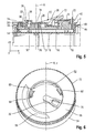
- einen perspektivischen Längsschnitt durch die in dem Geräteabschnitt eingesetzte Einstelleinrichtung,
- Figur 5
- einen zweidimensionalen Längsschnitt durch die in dem Geräteabschnitt eingesetzte Einstelleinrichtung,
- Figur 6
- eine perspektivische Einzeldarstellung eines Drehgriffs der Einstelleinrichtung,
- Figur 7
- einen perspektivischen Schnitt durch die Einstelleinrichtung im Bereich des Drehgriffs,
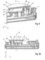
- Figur 8
- eine perspektivische Einzeldarstellung einer Abdeckung der Einstelleinrichtung,
- Figur 9
- einen Montageschritt der Abdeckung an dem Gehäuse, und
- Figur 10
- einen zweidimensionalen Längsschnitt durch das Gehäuse mit montierter Abdeckung.
- Gemäß den
Figuren 1 und 2 hat eine bevorzugte Einrichtung 1 zum Einstellen eines Betriebszustandes eines Haushaltsgerätes wie ein Bügeleisen ein Gehäuse 2 und einen Drehring 4, der an dem Gehäuse 2 um eine sich in Hochrichtung z erstreckende Rotationsachse bzw. Drehachse R drehbar gelagert ist. Die Einstelleinrichtung 1 ist beispielsweise ein Temperaturregler und ermöglicht die Einstellung verschiedener Temperaturen des Bügeleisens. Das Bügeleisen ist bevorzugterweise eine Dampfbügeleisen. - Wie in den
Figuren 3, 4 und5 gezeigt, ist das Gehäuse 2 ein quaderartiger flacher Hohlkörper mit einer größeren Ausdehnung in Längsrichtung x als in Querrichtung y. Es besteht aus einem Kunststoffmaterial und ist transparent bzw. lichtdurchlässig. Es weist eine Unterschale 6 und eine lösbar mit dieser verbundenen Oberschale 8 auf. Die Unterschale 6 und die Oberschale 8 begrenzen einen Innenraum 10 und sind über Rastverschlüsse 12 wasserdicht miteinander verbunden. In dem Innenraum 10 ist eine Geräteelektronik 14 angeordnet, die beispielsweise eine Platine 16, optische Anzeigenelemente 18 wie LEDs zum Anzeigen eines jeweiligen Betriebszustandes sowie elektrische Kontaktelemente 20 zum Verbinden der Platine 16 mit beispielsweise einer Stromversorgung des Bügeleisens aufweist. Zudem umfasst die Gerätelektronik 14 ein Elektronikelement wie ein Potentiometer 21 zum Einstellen einer Soll-Temperatur. Das Potentiometer 21 ist vorzugsweise ein elektronisches Potentiometer, kann jedoch auch ein mechanisches Potentiometer sein. - Das Gehäuse 2 hat in Längsrichtung x bzw. von einer Sohlenspitze des Bügeleisens aus betrachtet einen vorderen Bereich, in dem eine Radialführung 22 zum Führen des Drehrings 4 sowie zumindest eine ausstülpungsartige Kammer 24 zur Aufnahme eines der Anzeigenelemente 18 angeordnet ist. Die Radialführung 22 weist einen sich von der Oberschale 8 des Gehäuses 2 in Hochrichtung z erstreckenden Zylinderabschnitt 26 und eine Kreisscheibe 28 auf, die den Zylinderabschnitt 26 an seinem freien Kopfende verschließt. Der Zylinderabschnitt 26 und die Kreisscheibe 28 sind koaxial bzw. konzentrisch zur Rotationsachse R angeordnet. Die Kreisscheibe 28 ist ein integraler Bestandteil des Gehäuses 2 und somit ebenfalls transparent. Insbesondere dient sie zur Bildung einer Ringschulter 30.
- Zum Durchführen eines in
Figur 6 gezeigten Mitnehmers 32 des Drehrings 4 zur Herstellung einer Wirkverbindung zwischen dem Drehring 4 und dem Potentiometer 21, weist die Kreisscheibe 28 eine zur Rotationsachse R konzentrisch verlaufende Öffnung 34 auf. Ferner weist die Kreisscheibe 28 einen sich parallel zur Rotationsachse R in Hochrichtung z erstreckenden rohrartigen Körperabschnitt 36 auf, der eine Kreisscheibenöffnung 37 umgreift und einen radial inneren Kragen 38 zur lösbaren Verrastung mit einer inFigur 8 gezeigten Abdeckung 40 hat. - Zudem hat das Gehäuse 4, wie in
Figur 3 gezeigt, einen hinteren Bereich, der von dem vorderen Bereich entfernt ist. Der hintere Bereich weist zwei oberschalenseitige und in Querrichtung y des Gehäuses 2 betrachtet gegenüberliegende ausstülpungsartige Kammern 42, 44 zur Aufnahme jeweils eines der optischen Anzeigenelementen 18 auf. Zudem hat der hintere Bereich eine spalt- bzw. schlitzartige Öffnung 46 zur Durchführung der elektrischen Kontaktelemente 20, die oberschalenseitig zwischen den Kammern 42, 44 angeordnet ist. Bevorzugterweise wird die Öffnung 46 nach dem Durchführen der elektrischen Kontaktelemente 20 wasserdicht verschlossen. Zum Abdichten von Leckagespalten zwischen den elektrischen Kontaktelementen 20 und Innenwandungsabschnitten der Öffnung 46 kann die Öffnung 46 mit einem Deckel, einem Dichteinsatz, eingespritzten Kunststoffmaterial und dergleichen verschlossen sein. - Wie insbesondere in den
Figuren 4 und5 gezeigt, ist das Gehäuse 2 formschlüssig mit einem Geräteabschnitt eines Gerätegehäuses 48 des Haushaltsgerätes verbunden. Insbesondere ist es derart an dem Geräteabschnitt positioniert, dass es mit seinem hinteren Bereich und somit dem die elektrischen Kontaktelemente 20 aufnehmenden Bereich innerhalb des Gerätegehäuses 48 und mit seinem vorderen Bereich und somit mit dem den Drehring 4 aufnehmenden Bereich in einer Geräteöffnung 50 angeordnet ist. - Der Drehring 4 ist, wie in den
Figuren 6 und7 gezeigt, ein Hohlringkörper, der bodenseitig und somit mit einer, dem Gehäuse 2 zugewandten Unterseite geöffnet ist. Er hat neben dem Mitnehmer 32 insbesondere eine Innenumfangswandung 52, eine Außenumfangswandung 54 sowie eine Stirnwandung 56. Der Drehring 4 besteht aus einem lichtundurchlässigen Kunststoffmaterial, weist jedoch im Bereich seiner Stirnwandung 56 zumindest einen transparenten Wandungsabschnitt 58 auf. - Die Innenumfangswandung 52 ist gegenüber der Außenumfangswandung 54 in Hochrichtung z verkürzt. Sie ist von Rastarmen 60, 62, die sich von der Stirnwandung 56 in Richtung der Rotationsachse R erstrecken und in Umfangsrichtung gleichmäßig voneinander beabstandet sind, in einzelne Umfangsabschnitte unterteilt. Bei dem gezeigten Ausführungsbeispiel sind drei Rastarme 60, 62 vorgesehen, von denen in den
Figuren 6 und7 aufgrund der Perspektive jedoch lediglich zwei Rastarme 60, 62 sichtbar sind. Selbstverständlich sind auch weniger oder mehr als zwei Rastarme 60, 62 möglich. Die Rastarme 60, 62 sind gegenüber der Innenumfangswandung 52 verlängert und haben jeweils einen radial nach innen weisenden Hakenabschnitt 64 zur lösbaren Verrastung mit der Ringschulter 30. Zur Bildung einer radial inneren stirnseitigen und ringartigen Stützfläche 68 sind die Innenumfangswandung 52 bzw. deren Umfangsabschnitte sowie die Rastarme 60, 62 gegenüber der Stirnwandung 56 radial nach innen versetzt. - Die Außenumfangswandung 54 hat eine bodenseitige Ringfläche 70, mittels der der Drehring 4 im montierten Zustand auf einer gerätegehäuseseitigen Gleitfläche 72 geführt ist. Die Gleitfläche 72 ist, wie in den
Figuren 4 und5 gezeigt, eine Schulterfläche eines ringartigen Stegs, die bzw. der sich von einer Innenwandung 74 der Gehäuseöffnung 50 radial nach innen erstreckt und ein axiales Gleitlager für den Drehring 4 darstellt. Zur einfachen Handhabung bzw. Betätigung des Drehrings 4 kann die Außenwandung 54 mit einer Riffelung 73 versehen sein. - Die Stirnwandung 56 ist im montierten Zustand einem Benutzer zugewandt. Wie in
Figur 7 gezeigt ist, ist die Stirnwandung 56 im montierten Zustand des Drehrings 4 über der vorderen Kammer 24 angeordnet. Die Stirnwandung 56 verdeckt somit das Anzeigenelement 18 in Hochrichtung z und die Umfangswandungen 52, 54 verdecken die vordere Kammer 24 in Längsrichtung x und in Querrichtung y. Durch eine Drehung des Drehrings 4 kann jedoch der Wandungsabschnitt 58 in Überlappung bzw. Überdeckung mit dem Anzeigenelement 18 gebracht werden, wodurch aufgrund der Transparenz der Kammer 24 und des Wandungsabschnittes 58 der Benutzer erkennt, ob das Anzeigenelement 18 leuchtet und somit ein dem Anzeigenelement 18 zugeordneter Betriebszustand des Bügeleisens erreicht ist. - Der Mitnehmer 32 ist endseitig an einem sich von der Innenumfangswandung 52 radial nach innen erstreckenden Arm 76 angeordnet. Er ist zapfenartig ausgebildet und verläuft koaxial zur Rotationsachse R. Im montierten Zustand taucht er durch die Öffnung 34 der Kreisscheibe 28 ein und steht so mit dem sich gemäß der Darstellung in den Figuren unterhalb der Kreisscheibe 28 im Zylinderabschnitt 26 befindenen Potentiometer 21 in Wirkverbindung. Der Arm 76 erstreckt sich von einem der Umfangsabschnitte der Innenumfangswandung 52. Wie in
Figur 7 gezeigt, ist er in einem derart geringen axialen Abstand bzw. Abstand in Hochrichtung z von der Kreisscheibe 28 beabstandet, dass er bei einer Drehung des Drehrings 4 seitlich auf den sich von der Kreisscheibe 28 erstreckenden Körperabschnitt 36 aufläuft. Hierdurch wird eine in beide Drehrichtungen wirkende Drehbegrenzung gebildet und somit eine Überdrehung des Potentiometers 21 verhindert. - Vorzugsweise taucht der Mitnehmer 32 in ein in den
Figuren 4 und5 gezeigtes potentiometerseitiges hülsenartiges Element 78 ein. - Wie in
Figur 7 gezeigt, kann unterhalb der Kreisscheibe 28 im Zylinderabschnitt 26 ebenfalls ein Anzeigenelement 18 zum Anzeigen eines weiteren Betriebszustandes des Bügeleisens angeordnet sein. - Die Abdeckung 40 ist, wie in den
Figuren 8 ,9 und 10 gezeigt, ein kreisförmiger tellerartiger Körper mit einer Unterseite 82 und einer dem Benutzer zugewandten Sichtseite 84. Er besteht aus einem Kunststoffmaterial und ist transparent bzw. von dem Anzeigenelement 18 durchleuchtbar. Er hat zwei sich orthogonal von der Unterseite 82 erstreckende gegenüberliegende Rastvorsprünge 86, 88, die jeweils einen von dem gegenüberliegenden Rastvorsprung 86, 88 abgewandten Hakenabschnitt 90 haben. Die Rastvorsprünge 86, 88 dienen zur lösbaren Verrastung mit dem Gehäuse 2. Wie insbesondere in denFiguren 9 und 10 gezeigt, taucht die Abdeckung 40 dabei mit ihren Rastvorsprüngen 86, 88 in den Körperabschnitt 36 der Kreisscheibe 28 ein und verrastet lösbar mit dem Kragen 38. Somit ist die Abdeckung 40 drehfest an dem Gehäuse 2 angeordnet. Zudem hat die Abdeckung 40 einen sich von ihrer Unterseite 82 erstreckenden Ringsteg 92, der im Bereich der Rastvorsprünge 86, 88 erhöht bzw. in axialer Richtung verlängert ist. Der Ringsteg 92 wird von der Ringfläche 66 umgriffen, wobei er derart radial innenliegend zur Ringfläche 66 angeordnet ist, dass im montierten Zustand die Abdeckung 40 mit der Ringfläche 66 flächig auf der Stützfläche 68 des Drehrings 4 aufliegt. - Zur Montage der Einstelleinrichtung wird das Gehäuse 2 von innen an dem Geräteabschnitt des Gerätegehäuses 48 mit der in der Gehäuseöffnung 50 positionierten Radialführung 22 angebunden. Vorzugsweise erfolgt die Anbindung formschlüssig. Die elektrischen Kontaktelemente 20 sind somit innerhalb des Gerätegehäuses 48 angeordnet. Ebenso sind die Anzeigenelemente 18 in den hinteren Kammern 42, 44 innerhalb des Gerätegehäuses 48 angeordnet, so dass das Gerätegehäuse 48 zumindest im Positionsbereich der Kammern 42, 44 transparent ist. Dann wird der Drehring 4 in Richtung der Rotationsachse R von außen in der Gehäuseöffnung 50 auf der Radialführung 22 positioniert. Dabei wird der Mitnehmer 32 durch die Öffnung 34 in das hülsenartige Element 78 des Potentiometers 21 eingeführt und der Drehring 4 mittels der Rastarme 60, 62 mit der Radialschulter 30 lösbar verrastet. Der Drehring 4 ist nun drehbar an dem Gehäuse 2 geführt, wobei er in radialer Richtung innenumfangsseitig durch die Anlage der Rastarme 60, 62 an der Kreisscheibe 28 der Radialführung 22 und in axialer Richtung durch die Auflage seiner außenumfangsseitigen Ringfläche 70 auf der gehäuseseitige Gleitfläche 72 geführt ist. Eine maximale Verdrehung bzw. ein maximaler Drehwinkel wird durch ein Auflaufen des Arms 76 auf einen sich von der Kreisscheibe 28 erstreckenden Körperabschnitt 36 begrenzt. Danach wird die Radialführung 22 mittels der Abdeckung 40 abgedeckt. Hierzu wird die Abdeckung 40 mit ihren Rastvorsprüngen 86, 88 in den Körperabschnitt 36 eingeführt, die dann mit dessen Kragen 38 lösbar verrasten. Die Abdeckung 40 ist nun drehfest an dem Gehäuse 2 angeordnet, wobei sie sich axial mit ihrer Ringfläche 66 auf der Stützfläche 68 des Drehrings 4 und somit auf dem Gerätegehäuse 48 abstützt.
- Die Anzahl der Anzeigenelemente 18 sowie ihre Anordnung ist frei wählbar. Entscheidend ist, dass jeweils von dem Benutzer erkannt wird, ob sie bestromt sind bzw. leuchten oder nicht bestromt und somit nicht leuchtend sind. Die Anzeigenelemente 18 können an sich farbig sein. Alternativ können die die Anzeigenelemente 18 aufnehmenden transparenten Gehäuseabschnitte 24, 42, 44, die Anzeigenelemente 18 verdeckenden Gerätegehäuseabschnitte und/oder die Drehringabschnitte 58 farbig sein.
- Beispielsweise ist es vorstellbar ein Anzeigenelement 18 vorzusehen, das beim Erreichen einer Soll-Temperatur leuchtet und somit dem Benutzer signalisiert, dass das Bügeleisen betriebsbereit ist (bspw. grüne Beleuchtung). Ein Anzeigenelement 18 kann vorgesehen sein, um dem Benutzer anzuzeigen, dass die Soll-Temperatur überschritten ist (bspw. rote Beleuchtung). Ein Anzeigenelement 18 kann beispielsweise vorgesehen sein, um dem Benutzer zu signalisieren, dass die Soll-Temperatur noch nicht erreicht ist (bspw. orange Beleuchtung). Ein Anzeigenelement 18 kann vorgesehen sein, um dem Benutzer anzuzeigen, dass eine automatische Abschaltfunktion aktiviert ist (bspw. weiße Beleuchtung).
- Offenbart ist eine Einrichtung zum Einstellen eines Betriebszustandes eines Haushaltsgerätes, mit einem an einem Geräteabschnitt fixierbaren Gehäuse, in dem eine Elektronik des Haushaltsgerätes angeordnet ist, einem Drehgriff zum Ansteuern der Elektronik, der einen auf einer Drehachse gelagerten Mitnehmer hat, der sich im Wirkeingriff mit der Elektronik befindet, und wobei der Drehgriff zumindest einen transparenten Wandungsabschnitt aufweist, und mit zumindest einem optischen Anzeigenelement zum Anzeigen eines Betriebszustandes des Haushaltsgerätes, das von dem Drehgriff verdeckt ist und mit dem der transparente Wandungsabschnitt in Überlappung bringbar ist, wobei der Drehgriff ein Hohlringprofil ist, das an einer zur Drehachse konzentrischen Radialführung des Gehäuses geführt ist und einen in Richtung der Drehachse orientierten Arm hat, von dem sich der Mitnehmer erstreckt, sowie ein Bügeleisen mit einer derartigen Einstelleinrichtung, wobei die Einstelleinrichtung mit ihren elektrischen Kontaktelementen innerhalb des Bügeleisengehäuses und mit ihrer Radialführung außerhalb des Bügeleisengehäuses angeordnet ist.
-
- 1
- Einstelleinrichtung
- 2
- Gehäuse
- 4
- Drehring
- 6
- Unterschale
- 8
- Oberschale
- 10
- Innenraum
- 12
- Rastverschluss wasserdicht
- 14
- Elektronik
- 16
- Platine
- 18
- Anzeigenelement
- 20
- elektrisches Kontaktelement
- 21
- Potentiometer
- 22
- Radialführung
- 24
- Kammer
- 26
- Zylinderabschnitt
- 28
- Kreisscheibe
- 30
- Ringschulter
- 32
- Mitnehmer
- 34
- Öffnung
- 36
- Körperabschnitt
- 37
- Kreisscheibenöffnung
- 38
- Kragen
- 40
- Abdeckung drehfest
- 42
- Kammer
- 44
- Kammer
- 46
- Öffnung
- 48
- Gerätegehäuse
- 50
- Geräteöffnung
- 52
- Innenumfangswandung
- 54
- Außenumfangswandung
- 56
- Stirnwandung
- 58
- Wandungsabschnitt
- 60
- Rastarm
- 62
- Rastarm
- 64
- Hakenabschnitt
- 66
- Ringfläche
- 68
- Stützfläche
- 70
- Ringfläche
- 72
- Gleitfläche
- 74
- Innenwandung
- 73
- Riffelung
- 76
- Arm
- 78
- hülsenartiges Element
- 82
- Unterseite
- 84
- Sichtseite
- 86
- Rastvorsprung
- 88
- Rastvorsprung
- 90
- Hakenabschnitt
- 92
- Ringsteg
- R
- Rotationsachse
- x
- Längsrichtung
- y
- Querrichtung
- z
- Hochrichtung
Claims (10)
- Einrichtung (1) zum Einstellen eines Betriebszustandes eines Haushaltsgerätes, mit einem an einem Geräteabschnitt fixierbaren Gehäuse (2), in dem eine Elektronik (14) des Haushaltsgerätes angeordnet ist, einem Drehgriff (4) zum Ansteuern der Elektronik, der einen auf einer Drehachse (R) gelagerten Mitnehmer (32) hat, der sich im Wirkeingriff mit der Elektronik (14) befindet, und wobei der Drehgriff (4) zumindest einen transparenten Wandungsabschnitt (58) aufweist, und mit zumindest einem optischen Anzeigenelement (18) zum Anzeigen eines Betriebszustandes des Haushaltsgerätes, das von dem Drehgriff (4) verdeckt ist und mit dem der transparente Wandungsabschnitt (58) in Überlappung bringbar ist, dadurch gekennzeichnet, dass der Drehgriff (4) ein Hohlringprofil ist, das an einer zur Drehachse (R) konzentrischen Radialführung (22) des Gehäuses (2) geführt ist und einen in Richtung der Drehachse (R) orientierten Arm (76) hat, von dem sich der Mitnehmer (32) erstreckt.
- Einrichtung nach Anspruch 1, wobei der Drehgriff (4) eine Ringfläche (70) zur Abstützung an einer ringartigen Gleitfläche (72) des Geräteabschnitts hat.
- Einrichtung nach Anspruch 2, wobei die Radialführung (22) von einem Zylinderabschnitt (26) des Gehäuses (2) und von einer Ringschulter (30) gebildet ist, mit der der Drehgriff (4) lösbar verrastet.
- Einrichtung nach Anspruch 2 oder 3, wobei der Mitnehmer (32) ein durch eine Öffnung (34) des Zylinderabschnitts (26) geführter Zapfen ist.
- Einrichtung nach Anspruch 4, wobei der Arm (76) bei einer Drehbewegung in Anlage mit einem von dem Zylinderabschnitt (26) vorspringenden Körperabschnitt (36) bringbar ist.
- Einrichtung nach einem der vorhergehenden Ansprüche, wobei eine Abdeckung (40) zum Abdecken der Radialführung (22) vorgesehen ist.
- Einrichtung nach Anspruch 6, wobei sich die Abdeckung (40) mit einer Ringfläche (66) auf einer radial inneren Stützfläche (68) des Drehgriffs (4) abstützt.
- Einrichtung nach einem der vorhergehenden Ansprüche, wobei elektrische Kontaktelemente (20) zum Verbinden der Elektronik (14) in einem von der Radialführung (22) entfernten Gehäuseabschnitt angeordnet sind.
- Einrichtung nach einem der vorhergehenden Ansprüche, wobei die innerhalb des Gerätes positionierbaren Gehäuseabschnitte des Gehäuses (2) wasserdicht sind.
- Bügeleisen mit einer Einstelleinrichtung (1) nach einem der vorhergehenden Ansprüche, wobei die Einstelleinrichtung (1) mit ihren elektrische Kontaktelementen (20) innerhalb des Bügeleisengehäuses (48) angeordnet ist und mit ihrer Radialführung (22) außerhalb Bügeleisengehäuses (48).
Applications Claiming Priority (2)
| Application Number | Priority Date | Filing Date | Title |
|---|---|---|---|
| ES201231298A ES2442967B1 (es) | 2012-08-14 | 2012-08-14 | Dispositivo de ajuste de un aparato doméstico, y plancha |
| DE102012219291A DE102012219291B3 (de) | 2012-08-14 | 2012-10-23 | Einstelleinrichtung eines Haushaltsgerätes sowie Bügeleisen |
Publications (3)
| Publication Number | Publication Date |
|---|---|
| EP2698469A2 true EP2698469A2 (de) | 2014-02-19 |
| EP2698469A3 EP2698469A3 (de) | 2015-11-11 |
| EP2698469B1 EP2698469B1 (de) | 2017-01-11 |
Family
ID=48145450
Family Applications (1)
| Application Number | Title | Priority Date | Filing Date |
|---|---|---|---|
| EP13179274.9A Not-in-force EP2698469B1 (de) | 2012-08-14 | 2013-08-05 | Einstelleinrichtung eines Haushaltsgerätes sowie Bügeleisen |
Country Status (3)
| Country | Link |
|---|---|
| EP (1) | EP2698469B1 (de) |
| DE (1) | DE102012219291B3 (de) |
| ES (1) | ES2442967B1 (de) |
Cited By (1)
| Publication number | Priority date | Publication date | Assignee | Title |
|---|---|---|---|---|
| CN110236465A (zh) * | 2018-03-07 | 2019-09-17 | 青岛海尔洗碗机有限公司 | 一种喷淋组件及洗碗机 |
Citations (1)
| Publication number | Priority date | Publication date | Assignee | Title |
|---|---|---|---|---|
| DE3804369A1 (de) | 1988-02-12 | 1989-08-24 | Haebe Anni | Elektronischer temperatur - drehknopf - regler |
Family Cites Families (4)
| Publication number | Priority date | Publication date | Assignee | Title |
|---|---|---|---|---|
| DE938262C (de) * | 1950-08-25 | 1956-01-26 | Voigt & Haeffner Ag | Elektrisches Buegeleisen mit einstellbarem Temperaturregler |
| IT236665Y1 (it) * | 1995-02-16 | 2000-08-17 | Candy Spa | Lavastoviglie ad incasso con azionamento frontale di programmatoreelettromeccanico |
| CN201588124U (zh) * | 2009-12-17 | 2010-09-22 | 漳州灿坤实业有限公司 | 两用组合熨斗 |
| TR200909823A2 (tr) * | 2009-12-25 | 2011-07-21 | Bsh Ev Aletleri̇ San. Ve Ti̇c. A.Ş. | Kontrol düğmesine sahip bir ev aleti |
-
2012
- 2012-08-14 ES ES201231298A patent/ES2442967B1/es not_active Expired - Fee Related
- 2012-10-23 DE DE102012219291A patent/DE102012219291B3/de not_active Expired - Fee Related
-
2013
- 2013-08-05 EP EP13179274.9A patent/EP2698469B1/de not_active Not-in-force
Patent Citations (1)
| Publication number | Priority date | Publication date | Assignee | Title |
|---|---|---|---|---|
| DE3804369A1 (de) | 1988-02-12 | 1989-08-24 | Haebe Anni | Elektronischer temperatur - drehknopf - regler |
Cited By (1)
| Publication number | Priority date | Publication date | Assignee | Title |
|---|---|---|---|---|
| CN110236465A (zh) * | 2018-03-07 | 2019-09-17 | 青岛海尔洗碗机有限公司 | 一种喷淋组件及洗碗机 |
Also Published As
| Publication number | Publication date |
|---|---|
| EP2698469A3 (de) | 2015-11-11 |
| DE102012219291B3 (de) | 2013-05-16 |
| ES2442967A1 (es) | 2014-02-14 |
| EP2698469B1 (de) | 2017-01-11 |
| ES2442967B1 (es) | 2014-11-18 |
Similar Documents
| Publication | Publication Date | Title |
|---|---|---|
| DE102010034304B4 (de) | Durchflussregelventil | |
| EP2101957B1 (de) | Elektrogerät mit aufgerastetem drehbarem bedienungselement | |
| DE102010032784A1 (de) | Bedienvorrichtung | |
| DE2617691C2 (de) | Bedienungsorgan nach Art einer Fensterkurbel | |
| EP1415675A1 (de) | Ventil zum Einstellen des Volumenstromes bei einem Infusions- oder Transfusionsvorgang | |
| EP1772935A3 (de) | Halter-Anordnung für Kabel o.ä. mit einstellbaren Dreh-Rast-Positionen | |
| DE102011002410A1 (de) | Bedieneinrichtung für ein Elektrogerät | |
| DE3437779A1 (de) | Dampfbuegelgeraet fuer haushaltszwecke | |
| DE2250621B2 (de) | Drehknopf für eine Einstellwelle | |
| DE102007050033B3 (de) | Drehsteller mit im Drehring integriertem und beleuchtetem Stellzeiger | |
| EP2698469B1 (de) | Einstelleinrichtung eines Haushaltsgerätes sowie Bügeleisen | |
| DE69125135T2 (de) | Schalteraufbau | |
| DE102004025395B4 (de) | Druckreduzierventil mit Druckmessinstrument im Griff | |
| DE202012104023U1 (de) | Multifunktionsarmatur | |
| DE102017215656B4 (de) | Stellungsanzeiger sowie damit ausgestatteter Drehantrieb und Prozessventil | |
| EP3348718B1 (de) | Betätigungsvorrichtung für ein ventil einer ablaufanordnung für ein becken | |
| DE102013212814A1 (de) | Bedienvorrichtung mit einem Bedienelement mit Magnete gehaltene Kappe und Sockel sowie Haushaltsgerät mit einer derartigen Bedienvorrichtung | |
| DE202009012182U1 (de) | Ansteuermodul | |
| DE102005032509A1 (de) | Bedienelement | |
| DE202010012676U1 (de) | Strahlerleuchte | |
| DE102015210830A1 (de) | Werkzeugwechselvorrichtung mit Schnellantrieb | |
| DE3234555A1 (de) | Elektrischer druckgeber zur steuerung elektrischer oeldruckmelder im schmiermittelkreislauf von verbrennungsmotoren | |
| DE202004014184U1 (de) | Vorrichtung zum Reinigen eines Meßseils bei einem Seillängengeber | |
| EP3035147B1 (de) | Sicherbare vorrichtung zum betätigen eines elektronischen bauteils | |
| EP1318534B1 (de) | Aufnahme mit einer Achse zur Drehbedienung eines Schaltgeräts o. dgl. |
Legal Events
| Date | Code | Title | Description |
|---|---|---|---|
| AK | Designated contracting states |
Kind code of ref document: A2 Designated state(s): AL AT BE BG CH CY CZ DE DK EE ES FI FR GB GR HR HU IE IS IT LI LT LU LV MC MK MT NL NO PL PT RO RS SE SI SK SM TR |
|
| AX | Request for extension of the european patent |
Extension state: BA ME |
|
| PUAI | Public reference made under article 153(3) epc to a published international application that has entered the european phase |
Free format text: ORIGINAL CODE: 0009012 |
|
| RAP1 | Party data changed (applicant data changed or rights of an application transferred) |
Owner name: BSH HAUSGERAETE GMBH |
|
| PUAL | Search report despatched |
Free format text: ORIGINAL CODE: 0009013 |
|
| AK | Designated contracting states |
Kind code of ref document: A3 Designated state(s): AL AT BE BG CH CY CZ DE DK EE ES FI FR GB GR HR HU IE IS IT LI LT LU LV MC MK MT NL NO PL PT RO RS SE SI SK SM TR |
|
| AX | Request for extension of the european patent |
Extension state: BA ME |
|
| RIC1 | Information provided on ipc code assigned before grant |
Ipc: D06F 75/00 20060101AFI20151007BHEP Ipc: G05G 1/10 20060101ALI20151007BHEP Ipc: D06F 75/26 20060101ALI20151007BHEP Ipc: A47L 15/42 20060101ALI20151007BHEP Ipc: G05G 1/00 20080401ALI20151007BHEP |
|
| 17P | Request for examination filed |
Effective date: 20160511 |
|
| RBV | Designated contracting states (corrected) |
Designated state(s): AL AT BE BG CH CY CZ DE DK EE ES FI FR GB GR HR HU IE IS IT LI LT LU LV MC MK MT NL NO PL PT RO RS SE SI SK SM TR |
|
| GRAP | Despatch of communication of intention to grant a patent |
Free format text: ORIGINAL CODE: EPIDOSNIGR1 |
|
| INTG | Intention to grant announced |
Effective date: 20160829 |
|
| GRAS | Grant fee paid |
Free format text: ORIGINAL CODE: EPIDOSNIGR3 |
|
| GRAA | (expected) grant |
Free format text: ORIGINAL CODE: 0009210 |
|
| AK | Designated contracting states |
Kind code of ref document: B1 Designated state(s): AL AT BE BG CH CY CZ DE DK EE ES FI FR GB GR HR HU IE IS IT LI LT LU LV MC MK MT NL NO PL PT RO RS SE SI SK SM TR |
|
| REG | Reference to a national code |
Ref country code: GB Ref legal event code: FG4D Free format text: NOT ENGLISH |
|
| REG | Reference to a national code |
Ref country code: CH Ref legal event code: EP |
|
| REG | Reference to a national code |
Ref country code: AT Ref legal event code: REF Ref document number: 861398 Country of ref document: AT Kind code of ref document: T Effective date: 20170115 |
|
| REG | Reference to a national code |
Ref country code: IE Ref legal event code: FG4D Free format text: LANGUAGE OF EP DOCUMENT: GERMAN |
|
| REG | Reference to a national code |
Ref country code: DE Ref legal event code: R096 Ref document number: 502013006043 Country of ref document: DE |
|
| REG | Reference to a national code |
Ref country code: LT Ref legal event code: MG4D |
|
| REG | Reference to a national code |
Ref country code: NL Ref legal event code: MP Effective date: 20170111 |
|
| PG25 | Lapsed in a contracting state [announced via postgrant information from national office to epo] |
Ref country code: NL Free format text: LAPSE BECAUSE OF FAILURE TO SUBMIT A TRANSLATION OF THE DESCRIPTION OR TO PAY THE FEE WITHIN THE PRESCRIBED TIME-LIMIT Effective date: 20170111 |
|
| PG25 | Lapsed in a contracting state [announced via postgrant information from national office to epo] |
Ref country code: FI Free format text: LAPSE BECAUSE OF FAILURE TO SUBMIT A TRANSLATION OF THE DESCRIPTION OR TO PAY THE FEE WITHIN THE PRESCRIBED TIME-LIMIT Effective date: 20170111 Ref country code: LT Free format text: LAPSE BECAUSE OF FAILURE TO SUBMIT A TRANSLATION OF THE DESCRIPTION OR TO PAY THE FEE WITHIN THE PRESCRIBED TIME-LIMIT Effective date: 20170111 Ref country code: GR Free format text: LAPSE BECAUSE OF FAILURE TO SUBMIT A TRANSLATION OF THE DESCRIPTION OR TO PAY THE FEE WITHIN THE PRESCRIBED TIME-LIMIT Effective date: 20170412 Ref country code: IS Free format text: LAPSE BECAUSE OF FAILURE TO SUBMIT A TRANSLATION OF THE DESCRIPTION OR TO PAY THE FEE WITHIN THE PRESCRIBED TIME-LIMIT Effective date: 20170511 Ref country code: HR Free format text: LAPSE BECAUSE OF FAILURE TO SUBMIT A TRANSLATION OF THE DESCRIPTION OR TO PAY THE FEE WITHIN THE PRESCRIBED TIME-LIMIT Effective date: 20170111 Ref country code: NO Free format text: LAPSE BECAUSE OF FAILURE TO SUBMIT A TRANSLATION OF THE DESCRIPTION OR TO PAY THE FEE WITHIN THE PRESCRIBED TIME-LIMIT Effective date: 20170411 |
|
| REG | Reference to a national code |
Ref country code: FR Ref legal event code: PLFP Year of fee payment: 5 |
|
| PG25 | Lapsed in a contracting state [announced via postgrant information from national office to epo] |
Ref country code: PL Free format text: LAPSE BECAUSE OF FAILURE TO SUBMIT A TRANSLATION OF THE DESCRIPTION OR TO PAY THE FEE WITHIN THE PRESCRIBED TIME-LIMIT Effective date: 20170111 Ref country code: ES Free format text: LAPSE BECAUSE OF FAILURE TO SUBMIT A TRANSLATION OF THE DESCRIPTION OR TO PAY THE FEE WITHIN THE PRESCRIBED TIME-LIMIT Effective date: 20170111 Ref country code: RS Free format text: LAPSE BECAUSE OF FAILURE TO SUBMIT A TRANSLATION OF THE DESCRIPTION OR TO PAY THE FEE WITHIN THE PRESCRIBED TIME-LIMIT Effective date: 20170111 Ref country code: PT Free format text: LAPSE BECAUSE OF FAILURE TO SUBMIT A TRANSLATION OF THE DESCRIPTION OR TO PAY THE FEE WITHIN THE PRESCRIBED TIME-LIMIT Effective date: 20170511 Ref country code: LV Free format text: LAPSE BECAUSE OF FAILURE TO SUBMIT A TRANSLATION OF THE DESCRIPTION OR TO PAY THE FEE WITHIN THE PRESCRIBED TIME-LIMIT Effective date: 20170111 Ref country code: BG Free format text: LAPSE BECAUSE OF FAILURE TO SUBMIT A TRANSLATION OF THE DESCRIPTION OR TO PAY THE FEE WITHIN THE PRESCRIBED TIME-LIMIT Effective date: 20170411 Ref country code: SE Free format text: LAPSE BECAUSE OF FAILURE TO SUBMIT A TRANSLATION OF THE DESCRIPTION OR TO PAY THE FEE WITHIN THE PRESCRIBED TIME-LIMIT Effective date: 20170111 |
|
| REG | Reference to a national code |
Ref country code: DE Ref legal event code: R097 Ref document number: 502013006043 Country of ref document: DE |
|
| PG25 | Lapsed in a contracting state [announced via postgrant information from national office to epo] |
Ref country code: CZ Free format text: LAPSE BECAUSE OF FAILURE TO SUBMIT A TRANSLATION OF THE DESCRIPTION OR TO PAY THE FEE WITHIN THE PRESCRIBED TIME-LIMIT Effective date: 20170111 Ref country code: EE Free format text: LAPSE BECAUSE OF FAILURE TO SUBMIT A TRANSLATION OF THE DESCRIPTION OR TO PAY THE FEE WITHIN THE PRESCRIBED TIME-LIMIT Effective date: 20170111 Ref country code: SK Free format text: LAPSE BECAUSE OF FAILURE TO SUBMIT A TRANSLATION OF THE DESCRIPTION OR TO PAY THE FEE WITHIN THE PRESCRIBED TIME-LIMIT Effective date: 20170111 Ref country code: RO Free format text: LAPSE BECAUSE OF FAILURE TO SUBMIT A TRANSLATION OF THE DESCRIPTION OR TO PAY THE FEE WITHIN THE PRESCRIBED TIME-LIMIT Effective date: 20170111 |
|
| PLBE | No opposition filed within time limit |
Free format text: ORIGINAL CODE: 0009261 |
|
| STAA | Information on the status of an ep patent application or granted ep patent |
Free format text: STATUS: NO OPPOSITION FILED WITHIN TIME LIMIT |
|
| PG25 | Lapsed in a contracting state [announced via postgrant information from national office to epo] |
Ref country code: SM Free format text: LAPSE BECAUSE OF FAILURE TO SUBMIT A TRANSLATION OF THE DESCRIPTION OR TO PAY THE FEE WITHIN THE PRESCRIBED TIME-LIMIT Effective date: 20170111 Ref country code: DK Free format text: LAPSE BECAUSE OF FAILURE TO SUBMIT A TRANSLATION OF THE DESCRIPTION OR TO PAY THE FEE WITHIN THE PRESCRIBED TIME-LIMIT Effective date: 20170111 |
|
| 26N | No opposition filed |
Effective date: 20171012 |
|
| PG25 | Lapsed in a contracting state [announced via postgrant information from national office to epo] |
Ref country code: SI Free format text: LAPSE BECAUSE OF FAILURE TO SUBMIT A TRANSLATION OF THE DESCRIPTION OR TO PAY THE FEE WITHIN THE PRESCRIBED TIME-LIMIT Effective date: 20170111 |
|
| REG | Reference to a national code |
Ref country code: CH Ref legal event code: PL |
|
| PG25 | Lapsed in a contracting state [announced via postgrant information from national office to epo] |
Ref country code: MC Free format text: LAPSE BECAUSE OF FAILURE TO SUBMIT A TRANSLATION OF THE DESCRIPTION OR TO PAY THE FEE WITHIN THE PRESCRIBED TIME-LIMIT Effective date: 20170111 |
|
| PG25 | Lapsed in a contracting state [announced via postgrant information from national office to epo] |
Ref country code: CH Free format text: LAPSE BECAUSE OF NON-PAYMENT OF DUE FEES Effective date: 20170831 Ref country code: LI Free format text: LAPSE BECAUSE OF NON-PAYMENT OF DUE FEES Effective date: 20170831 |
|
| REG | Reference to a national code |
Ref country code: IE Ref legal event code: MM4A |
|
| REG | Reference to a national code |
Ref country code: BE Ref legal event code: MM Effective date: 20170831 |
|
| PG25 | Lapsed in a contracting state [announced via postgrant information from national office to epo] |
Ref country code: LU Free format text: LAPSE BECAUSE OF NON-PAYMENT OF DUE FEES Effective date: 20170805 |
|
| PG25 | Lapsed in a contracting state [announced via postgrant information from national office to epo] |
Ref country code: IE Free format text: LAPSE BECAUSE OF NON-PAYMENT OF DUE FEES Effective date: 20170805 |
|
| REG | Reference to a national code |
Ref country code: FR Ref legal event code: PLFP Year of fee payment: 6 |
|
| PG25 | Lapsed in a contracting state [announced via postgrant information from national office to epo] |
Ref country code: BE Free format text: LAPSE BECAUSE OF NON-PAYMENT OF DUE FEES Effective date: 20170831 |
|
| PG25 | Lapsed in a contracting state [announced via postgrant information from national office to epo] |
Ref country code: MT Free format text: LAPSE BECAUSE OF FAILURE TO SUBMIT A TRANSLATION OF THE DESCRIPTION OR TO PAY THE FEE WITHIN THE PRESCRIBED TIME-LIMIT Effective date: 20170111 |
|
| PG25 | Lapsed in a contracting state [announced via postgrant information from national office to epo] |
Ref country code: HU Free format text: LAPSE BECAUSE OF FAILURE TO SUBMIT A TRANSLATION OF THE DESCRIPTION OR TO PAY THE FEE WITHIN THE PRESCRIBED TIME-LIMIT; INVALID AB INITIO Effective date: 20130805 |
|
| REG | Reference to a national code |
Ref country code: AT Ref legal event code: MM01 Ref document number: 861398 Country of ref document: AT Kind code of ref document: T Effective date: 20180805 |
|
| PG25 | Lapsed in a contracting state [announced via postgrant information from national office to epo] |
Ref country code: CY Free format text: LAPSE BECAUSE OF NON-PAYMENT OF DUE FEES Effective date: 20170111 |
|
| PG25 | Lapsed in a contracting state [announced via postgrant information from national office to epo] |
Ref country code: MK Free format text: LAPSE BECAUSE OF FAILURE TO SUBMIT A TRANSLATION OF THE DESCRIPTION OR TO PAY THE FEE WITHIN THE PRESCRIBED TIME-LIMIT Effective date: 20170111 |
|
| PG25 | Lapsed in a contracting state [announced via postgrant information from national office to epo] |
Ref country code: AT Free format text: LAPSE BECAUSE OF NON-PAYMENT OF DUE FEES Effective date: 20180805 |
|
| PG25 | Lapsed in a contracting state [announced via postgrant information from national office to epo] |
Ref country code: TR Free format text: LAPSE BECAUSE OF FAILURE TO SUBMIT A TRANSLATION OF THE DESCRIPTION OR TO PAY THE FEE WITHIN THE PRESCRIBED TIME-LIMIT Effective date: 20170111 |
|
| PG25 | Lapsed in a contracting state [announced via postgrant information from national office to epo] |
Ref country code: AL Free format text: LAPSE BECAUSE OF FAILURE TO SUBMIT A TRANSLATION OF THE DESCRIPTION OR TO PAY THE FEE WITHIN THE PRESCRIBED TIME-LIMIT Effective date: 20170111 |
|
| PGFP | Annual fee paid to national office [announced via postgrant information from national office to epo] |
Ref country code: DE Payment date: 20200831 Year of fee payment: 8 Ref country code: FR Payment date: 20200820 Year of fee payment: 8 Ref country code: GB Payment date: 20200825 Year of fee payment: 8 |
|
| PGFP | Annual fee paid to national office [announced via postgrant information from national office to epo] |
Ref country code: IT Payment date: 20200831 Year of fee payment: 8 |
|
| REG | Reference to a national code |
Ref country code: DE Ref legal event code: R119 Ref document number: 502013006043 Country of ref document: DE |
|
| GBPC | Gb: european patent ceased through non-payment of renewal fee |
Effective date: 20210805 |
|
| PG25 | Lapsed in a contracting state [announced via postgrant information from national office to epo] |
Ref country code: IT Free format text: LAPSE BECAUSE OF NON-PAYMENT OF DUE FEES Effective date: 20210805 Ref country code: GB Free format text: LAPSE BECAUSE OF NON-PAYMENT OF DUE FEES Effective date: 20210805 Ref country code: FR Free format text: LAPSE BECAUSE OF NON-PAYMENT OF DUE FEES Effective date: 20210831 Ref country code: DE Free format text: LAPSE BECAUSE OF NON-PAYMENT OF DUE FEES Effective date: 20220301 |