EP2697337B1 - A luminescent converter, a phosphor enhanced light source or a luminaire having a cri larger than 80 - Google Patents
A luminescent converter, a phosphor enhanced light source or a luminaire having a cri larger than 80 Download PDFInfo
- Publication number
- EP2697337B1 EP2697337B1 EP12717488.6A EP12717488A EP2697337B1 EP 2697337 B1 EP2697337 B1 EP 2697337B1 EP 12717488 A EP12717488 A EP 12717488A EP 2697337 B1 EP2697337 B1 EP 2697337B1
- Authority
- EP
- European Patent Office
- Prior art keywords
- luminescent material
- light
- organic luminescent
- light source
- phosphor
- Prior art date
- Legal status (The legal status is an assumption and is not a legal conclusion. Google has not performed a legal analysis and makes no representation as to the accuracy of the status listed.)
- Active
Links
- OAICVXFJPJFONN-UHFFFAOYSA-N Phosphorus Chemical compound [P] OAICVXFJPJFONN-UHFFFAOYSA-N 0.000 title claims description 51
- 239000000463 material Substances 0.000 claims description 328
- 238000010521 absorption reaction Methods 0.000 claims description 24
- 125000000217 alkyl group Chemical group 0.000 claims description 20
- 229910052731 fluorine Inorganic materials 0.000 claims description 14
- 239000011737 fluorine Substances 0.000 claims description 14
- 230000003595 spectral effect Effects 0.000 claims description 13
- PXGOKWXKJXAPGV-UHFFFAOYSA-N Fluorine Chemical compound FF PXGOKWXKJXAPGV-UHFFFAOYSA-N 0.000 claims description 11
- 239000001257 hydrogen Substances 0.000 claims description 11
- 229910052739 hydrogen Inorganic materials 0.000 claims description 11
- 125000004435 hydrogen atom Chemical group [H]* 0.000 claims description 11
- 125000000956 methoxy group Chemical group [H]C([H])([H])O* 0.000 claims description 11
- 150000001875 compounds Chemical class 0.000 claims description 9
- 125000002080 perylenyl group Chemical group C1(=CC=C2C=CC=C3C4=CC=CC5=CC=CC(C1=C23)=C45)* 0.000 claims description 9
- 125000001449 isopropyl group Chemical group [H]C([H])([H])C([H])(*)C([H])([H])[H] 0.000 claims description 8
- 238000009877 rendering Methods 0.000 claims description 8
- 125000000999 tert-butyl group Chemical group [H]C([H])([H])C(*)(C([H])([H])[H])C([H])([H])[H] 0.000 claims description 8
- QVGXLLKOCUKJST-UHFFFAOYSA-N atomic oxygen Chemical compound [O] QVGXLLKOCUKJST-UHFFFAOYSA-N 0.000 claims description 7
- 239000001301 oxygen Substances 0.000 claims description 7
- 229910052760 oxygen Inorganic materials 0.000 claims description 7
- -1 perylene bisamide compound Chemical class 0.000 claims description 6
- 125000004093 cyano group Chemical group *C#N 0.000 claims description 5
- 125000001153 fluoro group Chemical group F* 0.000 claims description 3
- CSHWQDPOILHKBI-UHFFFAOYSA-N peryrene Natural products C1=CC(C2=CC=CC=3C2=C2C=CC=3)=C3C2=CC=CC3=C1 CSHWQDPOILHKBI-UHFFFAOYSA-N 0.000 claims description 3
- 229910019990 cerium-doped yttrium aluminum garnet Inorganic materials 0.000 claims description 2
- 239000010410 layer Substances 0.000 description 74
- 229920000642 polymer Polymers 0.000 description 22
- 239000000203 mixture Substances 0.000 description 19
- 239000011159 matrix material Substances 0.000 description 17
- 238000000295 emission spectrum Methods 0.000 description 15
- 239000002245 particle Substances 0.000 description 11
- 229920003229 poly(methyl methacrylate) Polymers 0.000 description 10
- 239000004926 polymethyl methacrylate Substances 0.000 description 10
- 238000000862 absorption spectrum Methods 0.000 description 7
- 230000008901 benefit Effects 0.000 description 6
- 238000004519 manufacturing process Methods 0.000 description 6
- 238000001228 spectrum Methods 0.000 description 6
- 230000000694 effects Effects 0.000 description 5
- 239000007787 solid Substances 0.000 description 5
- 239000000758 substrate Substances 0.000 description 5
- 239000004698 Polyethylene Substances 0.000 description 4
- GWEVSGVZZGPLCZ-UHFFFAOYSA-N Titan oxide Chemical compound O=[Ti]=O GWEVSGVZZGPLCZ-UHFFFAOYSA-N 0.000 description 4
- 238000013461 design Methods 0.000 description 4
- 238000000059 patterning Methods 0.000 description 4
- 229920000573 polyethylene Polymers 0.000 description 4
- 229920000139 polyethylene terephthalate Polymers 0.000 description 4
- PNEYBMLMFCGWSK-UHFFFAOYSA-N aluminium oxide Inorganic materials [O-2].[O-2].[O-2].[Al+3].[Al+3] PNEYBMLMFCGWSK-UHFFFAOYSA-N 0.000 description 3
- 238000006243 chemical reaction Methods 0.000 description 3
- 239000003086 colorant Substances 0.000 description 3
- 229910052593 corundum Inorganic materials 0.000 description 3
- 230000005284 excitation Effects 0.000 description 3
- 238000000695 excitation spectrum Methods 0.000 description 3
- 230000031700 light absorption Effects 0.000 description 3
- 239000004417 polycarbonate Substances 0.000 description 3
- 229920000515 polycarbonate Polymers 0.000 description 3
- 239000002356 single layer Substances 0.000 description 3
- 229910001845 yogo sapphire Inorganic materials 0.000 description 3
- IJGRMHOSHXDMSA-UHFFFAOYSA-N Atomic nitrogen Chemical compound N#N IJGRMHOSHXDMSA-UHFFFAOYSA-N 0.000 description 2
- 239000004793 Polystyrene Substances 0.000 description 2
- 150000001252 acrylic acid derivatives Chemical class 0.000 description 2
- 229920001577 copolymer Polymers 0.000 description 2
- 239000007788 liquid Substances 0.000 description 2
- 238000000034 method Methods 0.000 description 2
- 238000012986 modification Methods 0.000 description 2
- 230000004048 modification Effects 0.000 description 2
- 239000011368 organic material Substances 0.000 description 2
- 229920002223 polystyrene Polymers 0.000 description 2
- KOLFLIQDJSFQSS-UHFFFAOYSA-N CC(C)c1cccc2c1N(C(c1cc(F)c(-c(c3c(c(C4=[O]C(C)c5cccc6c5N4C4=[O]C6C[IH+]5CC(C)(C)C5)c5)c4c4)c5F)c5c1c1cc(F)c5-c3c4F)=O)C1=[O]C2C Chemical compound CC(C)c1cccc2c1N(C(c1cc(F)c(-c(c3c(c(C4=[O]C(C)c5cccc6c5N4C4=[O]C6C[IH+]5CC(C)(C)C5)c5)c4c4)c5F)c5c1c1cc(F)c5-c3c4F)=O)C1=[O]C2C KOLFLIQDJSFQSS-UHFFFAOYSA-N 0.000 description 1
- 238000002835 absorbance Methods 0.000 description 1
- 230000005540 biological transmission Effects 0.000 description 1
- 239000012876 carrier material Substances 0.000 description 1
- 239000011248 coating agent Substances 0.000 description 1
- 238000000576 coating method Methods 0.000 description 1
- 230000001419 dependent effect Effects 0.000 description 1
- 230000006866 deterioration Effects 0.000 description 1
- 238000000605 extraction Methods 0.000 description 1
- 239000011521 glass Substances 0.000 description 1
- 238000004020 luminiscence type Methods 0.000 description 1
- 229910052757 nitrogen Inorganic materials 0.000 description 1
- QJGQUHMNIGDVPM-UHFFFAOYSA-N nitrogen group Chemical group [N] QJGQUHMNIGDVPM-UHFFFAOYSA-N 0.000 description 1
- 238000013021 overheating Methods 0.000 description 1
- NAVHMDGYDGTJBG-UHFFFAOYSA-N perylene-1,2-dicarboxamide Chemical class C1=CC(C2=C(C(C(=O)N)=CC=3C2=C2C=CC=3)C(N)=O)=C3C2=CC=CC3=C1 NAVHMDGYDGTJBG-UHFFFAOYSA-N 0.000 description 1
- 238000000926 separation method Methods 0.000 description 1
- 229910019655 synthetic inorganic crystalline material Inorganic materials 0.000 description 1
- 238000012360 testing method Methods 0.000 description 1
Images


Classifications
-
- C—CHEMISTRY; METALLURGY
- C09—DYES; PAINTS; POLISHES; NATURAL RESINS; ADHESIVES; COMPOSITIONS NOT OTHERWISE PROVIDED FOR; APPLICATIONS OF MATERIALS NOT OTHERWISE PROVIDED FOR
- C09K—MATERIALS FOR MISCELLANEOUS APPLICATIONS, NOT PROVIDED FOR ELSEWHERE
- C09K11/00—Luminescent, e.g. electroluminescent, chemiluminescent materials
- C09K11/06—Luminescent, e.g. electroluminescent, chemiluminescent materials containing organic luminescent materials
-
- C—CHEMISTRY; METALLURGY
- C09—DYES; PAINTS; POLISHES; NATURAL RESINS; ADHESIVES; COMPOSITIONS NOT OTHERWISE PROVIDED FOR; APPLICATIONS OF MATERIALS NOT OTHERWISE PROVIDED FOR
- C09K—MATERIALS FOR MISCELLANEOUS APPLICATIONS, NOT PROVIDED FOR ELSEWHERE
- C09K11/00—Luminescent, e.g. electroluminescent, chemiluminescent materials
- C09K11/08—Luminescent, e.g. electroluminescent, chemiluminescent materials containing inorganic luminescent materials
- C09K11/77—Luminescent, e.g. electroluminescent, chemiluminescent materials containing inorganic luminescent materials containing rare earth metals
- C09K11/7766—Luminescent, e.g. electroluminescent, chemiluminescent materials containing inorganic luminescent materials containing rare earth metals containing two or more rare earth metals
- C09K11/7774—Aluminates
-
- H—ELECTRICITY
- H01—ELECTRIC ELEMENTS
- H01L—SEMICONDUCTOR DEVICES NOT COVERED BY CLASS H10
- H01L33/00—Semiconductor devices having potential barriers specially adapted for light emission; Processes or apparatus specially adapted for the manufacture or treatment thereof or of parts thereof; Details thereof
- H01L33/48—Semiconductor devices having potential barriers specially adapted for light emission; Processes or apparatus specially adapted for the manufacture or treatment thereof or of parts thereof; Details thereof characterised by the semiconductor body packages
- H01L33/50—Wavelength conversion elements
- H01L33/501—Wavelength conversion elements characterised by the materials, e.g. binder
- H01L33/502—Wavelength conversion materials
- H01L33/504—Elements with two or more wavelength conversion materials
-
- H—ELECTRICITY
- H05—ELECTRIC TECHNIQUES NOT OTHERWISE PROVIDED FOR
- H05B—ELECTRIC HEATING; ELECTRIC LIGHT SOURCES NOT OTHERWISE PROVIDED FOR; CIRCUIT ARRANGEMENTS FOR ELECTRIC LIGHT SOURCES, IN GENERAL
- H05B33/00—Electroluminescent light sources
- H05B33/12—Light sources with substantially two-dimensional radiating surfaces
-
- C—CHEMISTRY; METALLURGY
- C09—DYES; PAINTS; POLISHES; NATURAL RESINS; ADHESIVES; COMPOSITIONS NOT OTHERWISE PROVIDED FOR; APPLICATIONS OF MATERIALS NOT OTHERWISE PROVIDED FOR
- C09K—MATERIALS FOR MISCELLANEOUS APPLICATIONS, NOT PROVIDED FOR ELSEWHERE
- C09K2211/00—Chemical nature of organic luminescent or tenebrescent compounds
- C09K2211/10—Non-macromolecular compounds
- C09K2211/1003—Carbocyclic compounds
- C09K2211/1011—Condensed systems
-
- C—CHEMISTRY; METALLURGY
- C09—DYES; PAINTS; POLISHES; NATURAL RESINS; ADHESIVES; COMPOSITIONS NOT OTHERWISE PROVIDED FOR; APPLICATIONS OF MATERIALS NOT OTHERWISE PROVIDED FOR
- C09K—MATERIALS FOR MISCELLANEOUS APPLICATIONS, NOT PROVIDED FOR ELSEWHERE
- C09K2211/00—Chemical nature of organic luminescent or tenebrescent compounds
- C09K2211/10—Non-macromolecular compounds
- C09K2211/1018—Heterocyclic compounds
- C09K2211/1025—Heterocyclic compounds characterised by ligands
- C09K2211/1029—Heterocyclic compounds characterised by ligands containing one nitrogen atom as the heteroatom
-
- C—CHEMISTRY; METALLURGY
- C09—DYES; PAINTS; POLISHES; NATURAL RESINS; ADHESIVES; COMPOSITIONS NOT OTHERWISE PROVIDED FOR; APPLICATIONS OF MATERIALS NOT OTHERWISE PROVIDED FOR
- C09K—MATERIALS FOR MISCELLANEOUS APPLICATIONS, NOT PROVIDED FOR ELSEWHERE
- C09K2211/00—Chemical nature of organic luminescent or tenebrescent compounds
- C09K2211/10—Non-macromolecular compounds
- C09K2211/1018—Heterocyclic compounds
- C09K2211/1025—Heterocyclic compounds characterised by ligands
- C09K2211/1044—Heterocyclic compounds characterised by ligands containing two nitrogen atoms as heteroatoms
Definitions
- the invention relates to a phosphor enhanced light source comprising a luminescent product for converting light of a first color distribution to light of another color distribution.
- luminescent material is combined with a solid state light emitter to generate a light emission distribution which is experienced by users as white light.
- the color rendering index of the light emission distribution of the generated white light should be relatively high to have a good color rending index.
- inorganic luminescent materials that each emits light of a different color together with a solid state light emitter which emits light of a single color.
- Inorganic luminescent materials are stable and may be used at a relatively high temperature.
- inorganic luminescent materials are relatively expensive.
- remote organic phosphors which are mixes of organic luminescent materials and which are placed at a certain distance from the solid state light emitter.
- a limited set of stable organic luminescent materials are available such that it is difficult to manufacture a light source which has a large enough light emission at every color.
- WO2010/116294 discloses a luminescent converter for a phosphor-enhanced light source.
- the luminescent converter comprises a first luminescent material which absorbs at least a part of excitation light emitted by a light emitter of the phosphor-enhanced light source, and to convert at least a part of the absorbed excitation light into first emission light which comprises a longer wavelength compared to the excitation light.
- the luminescent converter further comprises a second luminescent material which comprises organic luminescent material and is configured to absorb at least a part of the first emission light emitted by the first luminescent material, and to convert at least a part of the absorbed first emission light into second emission light which has a longer wavelength compared to the first emission light.
- An effect of the luminescent converter is that the two-step light conversion generates a relatively small Stokes shift of the light emitted by the organic luminescent material.
- the width of the spectrum of the second emission light is limited to reduce an infrared part in the emission spectrum. As such, the efficiency is improved.
- a first aspect of the invention provides a phosphor-enhanced light source as claimed in claim 1.
- the second aspect of the invention provides a luminaire as claimed in claim 14.
- Advantageous embodiments are defined in the dependent claims.
- a phosphor-enhanced light source in accordance with the first aspect of the invention comprises a light source, a luminescent converter, the luminescent converter comprises a first organic luminescent material, a second organic luminescent material and a third inorganic luminescent material.
- the first organic luminescent material absorbs a first portion of light emitted by the light source and/or absorbs a portion of light emitted by at least one of the second organic luminescent material or the inorganic luminescent material.
- the first organic luminescent material converts at least a part of the absorbed light into light of a first color distribution.
- the second organic luminescent material absorbs a second portion of the light emitted by the light source and/or absorbs a portion of light emitted by at least one of the first organic luminescent material or the inorganic luminescent material.
- the second organic luminescent material converts at least a part of the absorbed light into light of a second color distribution.
- the inorganic luminescent material absorbs a third portion of the light emitted by the light source and/or absorbs a portion of light emitted by the first organic luminescent material or the second organic luminescent material.
- the inorganic luminescent material converts at least a part of the absorbed light into a third color distribution to compensate self-absorption of light by at least one of the first organic luminescent material and the second organic luminescent material.
- the light which is received by the luminescent converter is partly absorbed and is partly emitted through the luminescent converter.
- the first organic luminescent material is excited by the light of the light source or by light that is emitted by another luminescent material and emits light of the first color distribution.
- the second luminescent material is excited by the light of the light source or by light that is emitted by another luminescent material and emits light of the second color distribution.
- a light distribution is emitted by the luminescent converter comprises at least light that directly originates from the light source, and light of the first color distribution and of the second color distribution. If the specific amounts of organic luminescent material are chosen, white light may be emitted by the luminescent converter.
- CRI color rending index
- a light source that is often used in phosphor-enhanced light sources is a blue emitting light emitting solid state light emitter.
- Many known organic luminescent materials do not absorb blue strongly. Consequently, a relatively large amount of the specific organic luminescent material must be used to be able to convert enough blue light to light of the first or second color distribution.
- the light emission spectrum of the luminescent converter which comprises the first and second organic luminescent material lacks light in a specific spectral range which keeps the color rending index below a certain value, for example, below 80.
- the inventors have found that the effect of self-absorption may be compensated by adding a third luminescent material which is inorganic and which emits a third color distribution that compensates the self-absorption by the first and/or the second luminescent material.
- a third luminescent material which is inorganic and which emits a third color distribution that compensates the self-absorption by the first and/or the second luminescent material.
- a further advantage of the use of inorganic luminescent material is that this material is a stable material. Further, the luminescent converter is relatively cheap because of the small amount of inorganic phosphors.
- each luminescent material emits light of a specific color distribution.
- the specific color distribution may, for example, comprise a primary color having a specific bandwidth around a predefined wavelength, or may, for example, comprise a plurality of primary colors.
- the predefined wavelength is a mean wavelength of a radiant power spectral distribution.
- the light of a primary color for example, includes Red, Green, Blue, Yellow and Amber light.
- the specific color distribution may also comprise mixtures of a plurality of colors, such as the neighboring colors Green and Yellow.
- the first color distribution comprises red light.
- the second organic luminescent material is configured for only absorbing a portion of the light emitted by the light source and/or absorbing a portion of light by the inorganic luminescent material and the second color distribution comprises yellow light.
- the inorganic luminescent material is configured for only absorbing light the third portion of the light emitted by the light source, and the third color distribution comprises light in the spectral range from 490 nm to 560 nm.
- the yellow-emitting second organic luminescent material is subject to a relatively high amount of self-absorption which results in lack of green light in the light emission spectrum of a luminescent converter which only comprises the organic luminescent materials. This is compensated by the inorganic luminescent material of the embodiment.
- luminescent materials only absorb light of a lower wavelength than the light that is emitted by specific luminescent material. Therefore the inorganic luminescent material can only absorb light of the light source, and the second organic luminescent material only absorbs light that is emitted by the light source and/or light that is emitted by the inorganic luminescent material.
- the first organic luminescent material and second organic luminescent material are a stable organic luminescent material.
- the stable luminescent material is defined as a material which shows less than 10% decrease in luminescence in 100 hours under at least one of the following test condition.
- Luminescent material is molecularly dissolved in a polymer matrix such as polymethylmethacrylate (PMMA), polyethylene terepthalate (PET) or poly carbonate (PC) and the concentration is adjusted so that at a thickness of 200 micrometer the layer containing the luminescent molecules shows 10% absorption at 450nm.
- PMMA polymethylmethacrylate
- PET polyethylene terepthalate
- PC poly carbonate
- the layer is then placed in a thermo stated chamber and continuously irradiated using a laser emitting at 450nm.
- the atmosphere in the chamber housing the polymer layer may be: pure nitrogen, air or a mixture of pure nitrogen containing 0.1% oxygen.
- the second organic material is a compound according to formula (I) or (II): wherein
- Some known yellow-emitting organic luminescent materials have a low stability when irradiated with blue light.
- the inventors have found the above indicated class of organic luminescent materials that emit yellow light and have a high stability when irradiated with blue light.
- these materials have a relatively low absorbance of blue light and as such the effect of 'self-absorption' is more significantly present if the materials of this class are used.
- the addition of the inorganic luminescent material is important to obtain a light emission spectrum that has a relatively high color rendering index.
- the second organic luminescent material comprising a perylene monoamide compound according to formula (III) or (IV): or the second organic luminescent material comprising a fluorine substituted perylene bisamide compound according to formula (V) or (VI):
- the compounds of the embodiment are stable organic luminescent materials and as such very suitable for use in a phosphor-enhanced light source and they are able to convert light in the blue spectral range towards light in the yellow spectral range.
- At least one of the first organic luminescent material and the second organic luminescent material is a perylene derivative.
- Perylene derivatives have advantageous luminescent characteristics and a wide range of materials may be created each having different absorption / excitation spectra and emission spectra.
- the inorganic luminescent material comprises at least one of: YAG:Ce or LuAG:Ce.
- the luminescent converter comprises a layer comprising a mix of the first organic luminescent material, the second luminescent material, and the inorganic luminescent material.
- Manufacturing the luminescent converter which comprises the mix of luminescent material is relatively easy and, thus, relatively cheap.
- the materials have to be mixed only once and in one step the mix may be arranged in the phosphor-enhanced light source.
- the mix of luminescent material is often mixed with a matrix polymer to obtain a mix of material that can easily be applied in phosphor-enhanced light sources.
- the matrix polymer is a polymer in which the luminescent material is dispersed or molecularly dissolved.
- the polymer matrix may be chosen amongst polymers such as acrylates (for example polymethylmethacrylate), polycarbonate, polystyrene, polyethylene, polyethylene terepthalate, polyethylene naphtalate and their copolymers and blends.
- acrylates for example polymethylmethacrylate
- polycarbonate for example polyethylene
- polystyrene for example polystyrene
- polyethylene for example polyethylene
- polyethylene terepthalate polyethylene naphtalate
- polyethylene naphtalate polyethylene naphtalate
- the inorganic luminescent material may function as scattering material in the mixture of luminescent materials.
- luminescent material is applied in a layer of material. In such a layer light is often captured, for example, via internal reflection. Part of this captured light is often re-absorbed and thus lost which reduces the conversion efficiency of the luminescent converter.
- additional scattering material may be added to the luminescent layer.
- scattering material represents some kind of light loss which is not preferred.
- the inorganic luminescent material may act as scattering material improving the extraction of light generated inside the luminescent material.
- a further benefit when using a mixture of luminescent materials is that the appearance of the phosphor-enhanced light source is determined by the mixture of the luminescent materials rather than the appearance of the upper luminescent material as would be the case in a stacked configuration. This would generate a more natural appearance of the phosphor-enhanced light source which would reduce consumer confusion.
- the luminescent converter comprises a stack of at least three layers, wherein each layer comprises a single one luminescent material of the group of: the first organic luminescent material, the second luminescent material, and the inorganic luminescent material.
- each layer comprises a single one luminescent material of the group of: the first organic luminescent material, the second luminescent material, and the inorganic luminescent material.
- the specific luminescent materials may be put as the first layer to prevent the absorption of the light generated by the another luminescent material.
- the layered structure provides the benefit that the different layers with luminescent materials may be generated via a production process which is best suited for the specific luminescent material.
- organic luminescent materials are often soluble to generate a liquid having a specific viscosity.
- Such a liquid may, for example, be easily applied on a carrier material in a substantially uniform layer via well known spin-coat techniques.
- the inorganic luminescent material may not be soluble and as such the layer of first luminescent material may be generated via other techniques suitable for the chosen first luminescent material.
- the luminescent converter comprises a layer which locally comprises a first sub-area and a second sub-area.
- the first sub-area comprises a first material of the group of: the first organic luminescent material, the second luminescent material, and the inorganic luminescent material.
- the second sub-area comprises a second material of the group of: the first organic luminescent material, the second luminescent material, and the inorganic luminescent material.
- the second material is different from the first material.
- the first sub-area does not comprise the second material and the second sub-area does not comprise the first material.
- the layer may comprise other materials, like a matrix polymer. However, the layer comprises sub-areas with a single luminescent material and sub-areas with another single luminescent material.
- the layer comprises a pattern of different luminescent materials.
- an additional design parameter is obtained for optimizing the emitted color distribution by the phosphor-enhanced light source.
- the patterning may be performed by printing or coating a mixture of a matrix polymer with a specific luminescent material at specific positions and printing another mixture of the matrix polymer and another luminescent material at the areas in between the initially printed mixture. With a patterned luminescent layer it is prevented that light emitted by a specific luminescent material is absorbed by another specific luminescent.
- the patterning results in a spatial separation of the different luminescent materials and thereby the influence that they have on each other's light emission spectrum is reduced, which is specifically important if light of a specific color may not be absorbed by a luminescent material to obtain a high enough color rending index.
- the luminescent converter comprises a further layer comprising a third material of the group of: the first organic luminescent material, the second luminescent material, and the inorganic luminescent material, the third material being different from the first material and from the second material.
- the layer comprises a third sub-area which comprises a third material of the group of: the first organic luminescent material, the second luminescent material, and the inorganic luminescent material.
- the third material is different from the first material and is different from the second material.
- the third sub-area does not comprise the first material and does not comprise the second material.
- the first sub-area and the second sub-area do not comprise the third material.
- the layer with the three luminescent materials which are separated in space may be manufactured on a substrate, for example, a glass substrate.
- the luminescent converter comprises scattering particles.
- the scattering particles may comprise, for example, Al 2 O 3 and TiO 2 . Scattering particles may assist in obtaining a more diffuse and more uniform light emission by the luminescent converter.
- luminescent material is applied in a layer of material. In such a layer light is often captured, for example, via internal reflection. Part of this captured light is often re-absorbed and thus lost which reduces the conversion efficiency of the luminescent converter. To prevent the light to be captured inside a layer, additional scattering material may be added to the luminescent layer.
- a phosphor-enhanced light source which comprises a light source and a luminescent converter.
- the phosphor-enhanced light source according to the first aspect of the invention provides the same benefits as the luminescent converter and has similar embodiments with similar effects as the corresponding embodiments of the luminescent converter.
- the light source may be a solid state light emitter, such as a light emitting diode, a laser diode or an organic light emitting diode.
- the light source emits blue light.
- Light sources which emit in the blue spectral range are in general available as high power light sources and have a long lifetime. Further, several advantageous luminescent materials are available to convert the blue light towards yellow light, which is the light emitted by the first organic luminescent material, towards red light, which is the light emitted by the second organic luminescent material, and towards light in the spectral range of 490 to 560nm, which is the light emitted by the inorganic luminescent material.
- a gap is present between the light source and the luminescent converter.
- the gap prevents the direct conduction of heat from the light source towards the luminescent converter thereby preventing deterioration of the luminescent material because of overheating.
- the term "remote phosphor configuration" is used to indicate that there is a certain distance between the luminescent converter and the light source.
- the phosphor-enhanced light source has a light emission of which the color rendering index is larger than 75. In a further embodiment, the color rendering index is larger than 80.
- the light emission distribution of the phosphor-enhanced light source is a weighted sum of the first color distribution, the second color distribution, the third color distribution, and the remaining light of the light source. Therefore, the total light emission by the phosphor-enhanced has light in every color range and has a relatively high color rending index.
- a luminaire which comprises the phosphor-enhanced light source according to the first aspect of the invention.
- the luminaire according to the second aspect of the invention provides the same benefits as the phosphor-enhanced light source according to the first aspect of the invention and has similar embodiments with similar effects as the corresponding embodiments of the phosphor-enhanced light source.
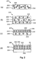
- Figs. 1a and 1b schematically present the phenomena of self-absorption.
- a layer 102 of a matrix polymer which comprises luminescent molecules 104, 108, 110.
- the size of the luminescent molecules 104, 108, 110 is exaggerated strongly for clarity reasons.
- the luminescent molecules 104, 108, 110 are of an organic luminescent material.
- the layer 102, which comprises the luminescent molecules 104, 108, 110 has good light transmission characteristics because the matrix polymer is transparent and does not show absorption of light. Further, the organic luminescent material is relatively transparent. Consequently, only the wavelengths falling within the absorption spectral range of the luminescent material are absorbed by the layer.
- Light 106 of a predefined color distribution impinges on one side of the layer 102. A portion of the light 106 is transmitted through the layer 102. Another portion of the light 106 is absorbed by the luminescent molecules 110.
- an excitation spectrum 152 is presented of the luminescent molecules 104, 108, 110.
- the x-axis represents the wavelength of light
- the y-axis represents the intensity of the light.
- Curve 152 represents the absorption spectrum showing at which specific wavelengths of light the luminescent molecules 104, 108, 110 absorb light.
- luminescent molecule 110 absorbs a part of the light 106 and emits light 112 of another color.
- the emission spectrum 156 of the luminescent molecules 104, 108, 110 is presented showing that the light emission may be at a plurality of wavelengths.
- the light that is emitted by luminescent molecule 110 is emitted in a plurality of directions.
- Luminescent molecule 108 receives also a portion of the light that is emitted by luminescent molecule 110.
- the absorption spectrum 152 and the light emissions spectrum 156 partly overlap and as such light that is emitted by the luminescent molecule 110 may be absorbed by luminescent molecule 108.
- the grey shaded area 154 represents the amount of light that is emitted by the luminescent molecules 104, 110, 108 that is absorbed by other luminescent molecules of the luminescent molecules 104, 110, 108 in a worst case. This phenomenon is called self-absorption.
- the amount of self-absorption strongly depends on the concentration of the luminescent molecules 104, 108, 110 in the layer 102 of the matrix polymer, and also depends, but to a lesser extent, on other factors like for example thickness of the layer 102 and a path length of the light within the layer before it escapes the layer. The more molecules are available, or the longer the path length is, the more the phenomenon of self-absorption is detectable. Because the light of the lower part of the light emission spectrum is absorbed, the average wavelength of the color distribution emitted by the layer of luminescent material shifts towards a higher wavelength.
- a yellow-emitting organic luminescent material which is identified to be stable, is used in combination with a light source that emits blue light
- a relatively large amount of yellow-emitting organic luminescent material has to be used because the absorption spectrum of the yellow-emitting organic luminescent material is located to a limited extend in the blue spectrum.
- the yellow-emitting organic material is not very sensitive for blue light and a relatively large amount of this material has to be used. Because of self-absorption, the light emission spectrum of the yellow-emitting organic luminescent material shifts towards a larger wavelength (thus, towards the red spectrum).
- a blue light source is combined with a yellow-emitting organic luminescent material and a red-emitting organic luminescent material, white light may be generated, however, because of the shift of the light emission of the yellow-emitting organic luminescent material, the color rendering index (CRI) of the white light is not high enough. It is relatively difficult to generate white light with a CRI that is higher than 80. In many applications the CRI has to be higher than 80 to obtain a good color rending.
- an inorganic luminescent material emitting in the green color spectrum is added to a combination of an organic yellow-emitting luminescent material and an organic red-emitting luminescent material, in order to obtain white light with a high enough CRI.
- the luminescent converter 200 is a layer 204 of a matrix polymer in which three different luminescent materials 202, 206, 208 are available.
- the matrix polymer is a polymer in which the luminescent material is dispersed or molecularly dissolved.
- the polymer matrix may be chosen amongst polymers such as acrylates (for example polymethylmethacrylate), polycarbonate, polystyrene, polyethylene, polyethylene terepthalate, polyethylene naphtalate and their copolymers and blends.
- Luminescent material 202 is an organic luminescent material that absorbs light that is emitted by a light source and converts a part of the absorbed light into light of first color distribution which comprises yellow light.
- luminescent material 202 is a yellow-emitting organic luminescent material.
- An example of such a material is the commercially named material Lumogen F Yellow 170, which is sold by BASF.
- the material is a perylene derivative.
- a specific class of perylene derivatives that is very stable when being irradiated with blue light comprises compounds according to formula (I) or (II): wherein
- One of the compound according to formula (I) is a fluorine substituted perylene bisamide compounds according to formula (V) or (VI):
- Luminescent material 206 is an inorganic luminescent material that absorbs light that is emitted by a light source and converts a part of the absorbed light into light of a third color distribution which comprises light in the spectral range from 490 nm to 560 nm.
- the inorganic luminescent material 206 emits green/yellow light and more specifically in a spectral range in which the yellow-emitting organic luminescent material 202 is subject to self-absorption.
- An example of such a material is the LuAG 3.5% FT 500 material or a Ce doped YAG.
- Luminescent material 208 is an organic luminescent material that absorbs light that is emitted by a light source and converts a part of the absorbed light into light of first color distribution which comprises red light.
- luminescent material 208 is a red-emitting organic luminescent material.
- An example of such a material is the commercially named material Lumogen F Red 305, which is sold by BASF.
- the material is a perylene derivative.
- the yellow-emitting luminescent material 202 may have a light absorption spectrum which also includes light in a portion of the spectrum range from 490 nm to 560nm. Consequently, the yellow-emitting luminescent material 202 may also absorb light emitted by the inorganic luminescent material 206.
- the red-emitting luminescent material 208 may also have an absorption spectrum which includes yellow and/or light in a portion of the spectral range from 490 nm to 560 nm. Consequently, the red-emitting luminescent material 208 may also absorb light emitted by the inorganic luminescent material 206 or by the yellow-emitting luminescent material 202.
- the luminescent converter 200 is manufactured as a single layer which comprises the three luminescent materials 202, 206, 208 in a mix. It is relatively easy and cheap to manufacture such a layer because the materials may be mixed with the matrix polymer and subsequently processed into a single layer.
- Luminescent converter 220 comprises three layers which each comprise a single luminescent material and which each comprises scattering particles 228 for further scattering light that is transmitted through the luminescent converter.
- the scattering particles 228 assist in a better light mixing and obtaining a substantially uniform light emission by the luminescent converter 220.
- the scattering particles may be made of the material Al 2 O 3 or TiO 2 .
- a first layer 226 of the luminescent converter 220 which faces, in use, towards a light source, comprises the red-emitting organic luminescent material 208.
- a second layer 224 which is manufactured on top of the first layer 226, comprises the yellow-emitting organic luminescent material 202.
- the third layer 222 which is manufactured on top of the second layer 224, comprises the green/yellow emitting inorganic luminescent material 206. The third layer is facing away from the light source and is in many applications used as the light emitting surface of a phosphor-enhanced light source comprising the luminescent converter 220.
- the configuration of the luminescent converter 220 provides additional design freedom because the order in which the luminescent materials 202, 206, 208 are placed in the stack of layers influences the light emission distribution at the light emitting surface of the luminescent converter 220.
- light emitted by the red-emitting organic luminescent material 208 may partly be absorbed in second layer 224 or in the third layer 222 by the yellow-emitting organic luminescent material 202 or the green/yellow-emitting inorganic luminescent material 206, respectively, to be converted towards yellow and green/yellow light, respectively.
- the luminescent materials 202, 206, 208 may also be arranged in another order in the layers 222, 224, 226 to obtain another light emission by the luminescent converter 220.
- the red-emitting organic luminescent material 208 mainly absorbs blue light emitted by the light source.
- the luminescent converter 240 comprises a base layer 244 which comprises the red-emitting organic luminescent material 208. On top of the base layer 244 is provided a patterned layer which comprises sub-areas 242, 246. Sub-areas 242 comprise the yellow-emitting organic luminescent material 202 and not the other luminescent materials 206, 208. Sub-areas 246 comprise the green/yellow-emitting inorganic luminescent material 206 and not the other luminescent materials 202, 208.
- An advantage of the patterned configuration of luminescent converter 240 is that the yellow/green-emitting luminescent material 206 and the yellow-emitting luminescent material 202 do not directly influence each other, and as such the green/yellow light emitted by the yellow/green-emitting luminescent material 206 is not absorbed by the yellow-emitting luminescent material 202 and vice versa.
- the pattern of the subareas 242, 246 may be obtained by printing the materials of the different subareas on top of the base layer 244.
- the luminescent converter 260 comprises a substrate layer 264 that is light transmitting and may be transparent in a practical embodiment.
- a patterned layer is provided which comprises different sub-areas 262, 266, 268.
- Each one of the sub-areas 262, 266, 268 comprises only one of the luminescent materials of the group of: the yellow-emitting organic luminescent material 202, the red-emitting organic luminescent material 208 and the green/yellow emitting luminescent material 206.
- each one of the luminescent materials does influence other luminescent materials to a limited extend if light is received at the side of the substrate layer 264 and has to be emitted at an opposite side of the luminescent converter 260.
- the luminescent material 202, 206, 208 is schematically drawn as spheres in a layer of a specific material.
- Organic luminescent materials are composed of molecules and as such the spheres schematically represent molecules if the specific luminescent material is an organic luminescent material.
- the organic molecules are molecularly dissolved in the material which forms the layer, for example, the matrix polymer.
- the inorganic luminescent material and the scattering particles are particles that are dispersed in the material that forms the layer, which is, for example, a matrix polymer.
- the inorganic luminescent particles and/or scattering particles have dimensions in the order of 0.1 to 10 micrometer. Fig.
- the first layer 226 is 54 ⁇ m thick and has 0.38 wt% of Lumogen F Red 305
- the second layer 224 is 81 ⁇ m thick and has 0.1 wt% Lumogen F Yellow 170
- the third layer 222 is 75 ⁇ m thick and has 50 wt% LuAG.
- Each one of the layers has as matrix polymer Polymethylmethacrylate (PMMA).
- PMMA matrix polymer Polymethylmethacrylate
- the color temperature of the obtained light emission is 3000K and the CRI is larger than 80. It is seen in Fig. 3a that the phosphor enhanced light source also emits light in the spectral range from 490 to 560nm which results in the relatively high CRI.
- Fig. 3b presents a light emission spectrum 350 of a phosphor enhanced light source which comprises a blue LED and a luminescent converter 240.
- the luminescent converter has a base layer of PMMA that is 27 ⁇ m thick and comprises 0.05 wt% Lumogen F Red 305.
- the sub-areas 242 with the yellow-emitting organic luminescent material 202 are portions of a PMMA layer that is 210 ⁇ m thick and comprises 0.01 wt% Lumogen F Yellow 170 on top of which a scattering layer of 60 ⁇ m layer of PMMA is provided that comprises Al2O3 particles.
- the sub-areas 246 with the green-yellow-emitting inorganic luminescent material 206 are portions of a PMMA layer that is 200 ⁇ m thick and comprises 50 wt% LuAG.
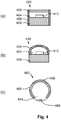
- Fig. 4 presents three embodiments of a phosphor enhanced light source 400, 430, 460.
- Phosphor enhanced light source 400 comprises a base 408 on which a blue emitting LED 410 is provided.
- a lighting mixing chamber 404 is enclosed by the base 408, walls 406 and a luminescent converter 402.
- a surface of the base and a surface of the walls facing towards the light mixing chamber 404 may be light reflective.
- the blue or UV LED 410 emit blue light towards the luminescent converter 402, which converts at least portions of the light emitted by the LED 410 towards yellow, red and green/yellow light.
- the phosphor enhanced light source 400 may have a light emission spectrum according to Fig. 3a if the luminescent converter discussed in the context of Fig. 3a is used and if the LED emits blue light.
- Another embodiment of the phosphor-enhanced light source 430 does not comprise walls, but comprises a curved luminescent converter 432 which encloses the light mixing chamber 404.
- Phosphor-enhanced light source 460 is a retro-fit fluorescent light tube. A cross-section of the light tube 466 is presented. In the inner chamber 464 of the light tube 466 is provided a blue LED 468. Along the length of the light tube 466 a plurality of such LEDs 468 may be provided. The blue LED 468 emits blue light towards a luminescent converter 462. The luminescent converter 462 is applied to an inner surface of the light tube 466 which faces towards the inner chamber 464 of the light tube 466.
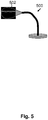
- Fig. 5 presents an embodiment of a luminaire 500 according to a second aspect of the invention.
- the luminaire 500 comprises a phosphor-enhanced light source 502 according to the first aspect of the invention.
Landscapes
- Chemical & Material Sciences (AREA)
- Engineering & Computer Science (AREA)
- Materials Engineering (AREA)
- Organic Chemistry (AREA)
- Microelectronics & Electronic Packaging (AREA)
- Manufacturing & Machinery (AREA)
- Computer Hardware Design (AREA)
- Power Engineering (AREA)
- Inorganic Chemistry (AREA)
- Led Device Packages (AREA)
- Luminescent Compositions (AREA)
- Electroluminescent Light Sources (AREA)
Priority Applications (1)
| Application Number | Priority Date | Filing Date | Title |
|---|---|---|---|
| EP12717488.6A EP2697337B1 (en) | 2011-04-12 | 2012-04-03 | A luminescent converter, a phosphor enhanced light source or a luminaire having a cri larger than 80 |
Applications Claiming Priority (3)
| Application Number | Priority Date | Filing Date | Title |
|---|---|---|---|
| EP11162040 | 2011-04-12 | ||
| PCT/IB2012/051621 WO2012140542A1 (en) | 2011-04-12 | 2012-04-03 | A luminescent converter, a phosphor enhanced light source or a luminaire having a cri larger than 80 |
| EP12717488.6A EP2697337B1 (en) | 2011-04-12 | 2012-04-03 | A luminescent converter, a phosphor enhanced light source or a luminaire having a cri larger than 80 |
Publications (2)
| Publication Number | Publication Date |
|---|---|
| EP2697337A1 EP2697337A1 (en) | 2014-02-19 |
| EP2697337B1 true EP2697337B1 (en) | 2019-06-12 |
Family
ID=46018021
Family Applications (1)
| Application Number | Title | Priority Date | Filing Date |
|---|---|---|---|
| EP12717488.6A Active EP2697337B1 (en) | 2011-04-12 | 2012-04-03 | A luminescent converter, a phosphor enhanced light source or a luminaire having a cri larger than 80 |
Country Status (6)
| Country | Link |
|---|---|
| US (1) | US20140021857A1 (zh) |
| EP (1) | EP2697337B1 (zh) |
| JP (1) | JP6032766B2 (zh) |
| CN (1) | CN103582689B (zh) |
| ES (1) | ES2743689T3 (zh) |
| WO (1) | WO2012140542A1 (zh) |
Families Citing this family (15)
| Publication number | Priority date | Publication date | Assignee | Title |
|---|---|---|---|---|
| WO2012153212A1 (en) * | 2011-05-06 | 2012-11-15 | Koninklijke Philips Electronics N.V. | Phosphor-enhanced lighting device, retrofit light bulb and light tube with reduced color appearance |
| CN104812869B (zh) * | 2012-11-30 | 2019-05-21 | 默克专利有限公司 | 波长转换聚合物膜 |
| WO2014122071A1 (en) | 2013-02-11 | 2014-08-14 | Koninklijke Philips N.V. | Increasing the lifetime of an organic phosphor by using off-maximum excitation |
| US9969932B2 (en) | 2013-03-01 | 2018-05-15 | Philips Lighting Holding B.V. | Class of green/yellow emitting phosphors based on benzoxanthene derivatives for LED lighting |
| US9142732B2 (en) * | 2013-03-04 | 2015-09-22 | Osram Sylvania Inc. | LED lamp with quantum dots layer |
| JP6246622B2 (ja) * | 2014-03-05 | 2017-12-13 | シャープ株式会社 | 光源装置および照明装置 |
| DE102014112551A1 (de) * | 2014-09-01 | 2016-03-03 | Osram Opto Semiconductors Gmbh | Optoelektronischer Halbleiterchip und Verfahren zur Herstellung eines optoelektronischen Halbleiterchips |
| CN107110432B (zh) | 2014-10-07 | 2020-02-04 | 飞利浦照明控股有限公司 | 用于发光光导的颜色控制 |
| KR102510808B1 (ko) * | 2015-02-23 | 2023-03-17 | 코닌클리케 필립스 엔.브이. | 개선된 색 균일성을 갖는 광원 조립체 |
| FR3035268A1 (fr) * | 2015-04-20 | 2016-10-21 | Photofuel | Dispositif d'eclairage emettant une lumiere blanche |
| TWI635622B (zh) * | 2015-06-10 | 2018-09-11 | 隆達電子股份有限公司 | 發光結構、燈具及背光模組 |
| CN107833962A (zh) * | 2016-08-22 | 2018-03-23 | 深圳市欧弗德光电科技有限公司 | 含有有机绿光、黄光及红光光致发光材料组合物的具有ofed结构的光源体及其应用 |
| JP6768480B2 (ja) * | 2016-12-09 | 2020-10-14 | 株式会社ジャパンディスプレイ | 液晶表示装置 |
| JP2019035700A (ja) * | 2017-08-18 | 2019-03-07 | セイコーエプソン株式会社 | エンコーダー、ロボットおよびプリンター |
| EP3637180A1 (en) * | 2018-10-11 | 2020-04-15 | SABIC Global Technologies B.V. | Polymer rail with moisture and oxygen stable quantum dots |
Family Cites Families (12)
| Publication number | Priority date | Publication date | Assignee | Title |
|---|---|---|---|---|
| DE29724847U1 (de) * | 1996-06-26 | 2004-09-30 | Osram Opto Semiconductors Gmbh | Lichtabstrahlendes Halbleiterbauelement mit Lumineszenzkonversionselement |
| JPH10154830A (ja) * | 1996-09-27 | 1998-06-09 | Nichia Chem Ind Ltd | 発光装置及びそれを用いた表示装置 |
| DE10243906A1 (de) * | 2002-09-20 | 2004-04-01 | Basf Ag | 9-Cyanosubstituierte Perylen-3,4-dicarbonsäuremonoimide |
| CN101925212A (zh) * | 2002-10-18 | 2010-12-22 | 伊菲雷知识产权公司 | 彩色电致发光显示器 |
| KR100668609B1 (ko) * | 2004-09-24 | 2007-01-16 | 엘지전자 주식회사 | 백색광원소자 |
| JP2006278980A (ja) * | 2005-03-30 | 2006-10-12 | Sanyo Electric Co Ltd | 半導体発光装置 |
| JP2006313817A (ja) * | 2005-05-09 | 2006-11-16 | Taiwan Oasis Technology Co Ltd | 多波長の発光ダイオード構造及びその製造工程 |
| WO2007013478A1 (en) * | 2005-07-25 | 2007-02-01 | Semiconductor Energy Laboratory Co., Ltd. | Light-emitting element, light-emitting device, and electronic appliance |
| KR100806812B1 (ko) * | 2005-07-25 | 2008-02-25 | 엘지.필립스 엘시디 주식회사 | 유기 el 소자 및 그 제조방법 |
| WO2009024512A1 (de) * | 2007-08-17 | 2009-02-26 | Basf Se | Halogenhaltige perylentetracarbonsäurederivate und deren verwendung |
| US8299701B2 (en) * | 2007-12-27 | 2012-10-30 | Ge Lighting Solutions Llc | Lighting device having illumination, backlighting and display applications |
| CN102378801B (zh) * | 2009-04-06 | 2014-06-04 | 皇家飞利浦电子股份有限公司 | 用于包括有机和无机磷光体的磷光体增强型光源的发光转换器 |
-
2012
- 2012-04-03 ES ES12717488T patent/ES2743689T3/es active Active
- 2012-04-03 JP JP2014504415A patent/JP6032766B2/ja not_active Expired - Fee Related
- 2012-04-03 US US14/009,865 patent/US20140021857A1/en active Pending
- 2012-04-03 CN CN201280027177.XA patent/CN103582689B/zh active Active
- 2012-04-03 EP EP12717488.6A patent/EP2697337B1/en active Active
- 2012-04-03 WO PCT/IB2012/051621 patent/WO2012140542A1/en active Application Filing
Non-Patent Citations (1)
| Title |
|---|
| None * |
Also Published As
| Publication number | Publication date |
|---|---|
| CN103582689B (zh) | 2017-03-01 |
| US20140021857A1 (en) | 2014-01-23 |
| ES2743689T3 (es) | 2020-02-20 |
| CN103582689A (zh) | 2014-02-12 |
| WO2012140542A1 (en) | 2012-10-18 |
| JP2014518007A (ja) | 2014-07-24 |
| JP6032766B2 (ja) | 2016-11-30 |
| EP2697337A1 (en) | 2014-02-19 |
Similar Documents
| Publication | Publication Date | Title |
|---|---|---|
| EP2697337B1 (en) | A luminescent converter, a phosphor enhanced light source or a luminaire having a cri larger than 80 | |
| EP2417219B1 (en) | Luminescent converter for a phosphor- enhanced light source comprising organic and inorganic phosphors | |
| RU2623682C2 (ru) | Модуль излучения белого света | |
| JP4477854B2 (ja) | 蛍光体変換発光デバイス | |
| US20160308098A1 (en) | Phosphor converted light emitting diode, a lamp and a luminaire | |
| KR101408508B1 (ko) | 발광 장치 | |
| KR101265094B1 (ko) | 백색 발광 다이오드 및 그 제조 방법 | |
| JP2019021890A (ja) | Led発光装置 | |
| US20170047488A1 (en) | Light emitting device | |
| US9897285B2 (en) | Wavelength converting element | |
| US20140191273A1 (en) | Light-emitting arrangement | |
| TW201224112A (en) | Light conversion layer comprising an organic phosphor combination | |
| US20130341590A1 (en) | Quantum Dot Narrow-Band Downconverters for High Efficiency LEDs | |
| JP3195229U (ja) | 発光デバイス | |
| US9837585B2 (en) | Light emitting device | |
| Huang et al. | Ca3Si2O4N2: Ce3+, Li+ Phosphor for the Generation of White‐Light‐Emitting Diodes with Excellent Color Rendering Index Values | |
| KR101706600B1 (ko) | 고연색성 백색 발광 소자 | |
| JP2009123675A (ja) | 照明装置 | |
| KR101652258B1 (ko) | 고연색성 백색 발광 소자 | |
| KR20180021748A (ko) | 고연색성 백색 발광 소자 | |
| KR101855391B1 (ko) | 고연색성 백색 발광 소자 | |
| KR102637411B1 (ko) | 적색 발광 형광체 및 이를 이용한 발광 장치 | |
| TW201300704A (zh) | 發光轉換器、磷光體強化光源或具有大於80之演色性指數之照明器具 | |
| KR102532154B1 (ko) | 형광체 및 이를 이용한 발광 소자 패키지 | |
| US20090189168A1 (en) | White Light Emitting Device |
Legal Events
| Date | Code | Title | Description |
|---|---|---|---|
| PUAI | Public reference made under article 153(3) epc to a published international application that has entered the european phase |
Free format text: ORIGINAL CODE: 0009012 |
|
| 17P | Request for examination filed |
Effective date: 20131112 |
|
| AK | Designated contracting states |
Kind code of ref document: A1 Designated state(s): AL AT BE BG CH CY CZ DE DK EE ES FI FR GB GR HR HU IE IS IT LI LT LU LV MC MK MT NL NO PL PT RO RS SE SI SK SM TR |
|
| DAX | Request for extension of the european patent (deleted) | ||
| RAP1 | Party data changed (applicant data changed or rights of an application transferred) |
Owner name: PHILIPS LIGHTING HOLDING B.V. |
|
| STAA | Information on the status of an ep patent application or granted ep patent |
Free format text: STATUS: EXAMINATION IS IN PROGRESS |
|
| 17Q | First examination report despatched |
Effective date: 20170112 |
|
| RIN1 | Information on inventor provided before grant (corrected) |
Inventor name: HIKMET, RIFAT ATA MUSTAFA Inventor name: VAN BOMMEL, TIES Inventor name: KRIEGE, JAN CORNELIS |
|
| RIC1 | Information provided on ipc code assigned before grant |
Ipc: C09K 11/06 20060101AFI20181023BHEP Ipc: H01L 33/50 20100101ALI20181023BHEP Ipc: H05B 33/14 20060101ALI20181023BHEP Ipc: H05B 33/12 20060101ALI20181023BHEP Ipc: H01L 51/50 20060101ALI20181023BHEP |
|
| GRAP | Despatch of communication of intention to grant a patent |
Free format text: ORIGINAL CODE: EPIDOSNIGR1 |
|
| STAA | Information on the status of an ep patent application or granted ep patent |
Free format text: STATUS: GRANT OF PATENT IS INTENDED |
|
| RAP1 | Party data changed (applicant data changed or rights of an application transferred) |
Owner name: PHILIPS LIGHTING HOLDING B.V. |
|
| RIC1 | Information provided on ipc code assigned before grant |
Ipc: H01L 33/50 20100101ALI20181122BHEP Ipc: C09K 11/06 20060101AFI20181122BHEP |
|
| INTG | Intention to grant announced |
Effective date: 20181211 |
|
| RAP1 | Party data changed (applicant data changed or rights of an application transferred) |
Owner name: SIGNIFY HOLDING B.V. |
|
| GRAS | Grant fee paid |
Free format text: ORIGINAL CODE: EPIDOSNIGR3 |
|
| GRAA | (expected) grant |
Free format text: ORIGINAL CODE: 0009210 |
|
| STAA | Information on the status of an ep patent application or granted ep patent |
Free format text: STATUS: THE PATENT HAS BEEN GRANTED |
|
| AK | Designated contracting states |
Kind code of ref document: B1 Designated state(s): AL AT BE BG CH CY CZ DE DK EE ES FI FR GB GR HR HU IE IS IT LI LT LU LV MC MK MT NL NO PL PT RO RS SE SI SK SM TR |
|
| REG | Reference to a national code |
Ref country code: GB Ref legal event code: FG4D |
|
| REG | Reference to a national code |
Ref country code: CH Ref legal event code: EP |
|
| REG | Reference to a national code |
Ref country code: AT Ref legal event code: REF Ref document number: 1142524 Country of ref document: AT Kind code of ref document: T Effective date: 20190615 |
|
| REG | Reference to a national code |
Ref country code: DE Ref legal event code: R096 Ref document number: 602012060900 Country of ref document: DE |
|
| REG | Reference to a national code |
Ref country code: IE Ref legal event code: FG4D |
|
| REG | Reference to a national code |
Ref country code: SE Ref legal event code: TRGR |
|
| REG | Reference to a national code |
Ref country code: NL Ref legal event code: MP Effective date: 20190612 |
|
| REG | Reference to a national code |
Ref country code: LT Ref legal event code: MG4D |
|
| PG25 | Lapsed in a contracting state [announced via postgrant information from national office to epo] |
Ref country code: FI Free format text: LAPSE BECAUSE OF FAILURE TO SUBMIT A TRANSLATION OF THE DESCRIPTION OR TO PAY THE FEE WITHIN THE PRESCRIBED TIME-LIMIT Effective date: 20190612 Ref country code: LT Free format text: LAPSE BECAUSE OF FAILURE TO SUBMIT A TRANSLATION OF THE DESCRIPTION OR TO PAY THE FEE WITHIN THE PRESCRIBED TIME-LIMIT Effective date: 20190612 Ref country code: AL Free format text: LAPSE BECAUSE OF FAILURE TO SUBMIT A TRANSLATION OF THE DESCRIPTION OR TO PAY THE FEE WITHIN THE PRESCRIBED TIME-LIMIT Effective date: 20190612 Ref country code: NO Free format text: LAPSE BECAUSE OF FAILURE TO SUBMIT A TRANSLATION OF THE DESCRIPTION OR TO PAY THE FEE WITHIN THE PRESCRIBED TIME-LIMIT Effective date: 20190912 Ref country code: HR Free format text: LAPSE BECAUSE OF FAILURE TO SUBMIT A TRANSLATION OF THE DESCRIPTION OR TO PAY THE FEE WITHIN THE PRESCRIBED TIME-LIMIT Effective date: 20190612 |
|
| PG25 | Lapsed in a contracting state [announced via postgrant information from national office to epo] |
Ref country code: GR Free format text: LAPSE BECAUSE OF FAILURE TO SUBMIT A TRANSLATION OF THE DESCRIPTION OR TO PAY THE FEE WITHIN THE PRESCRIBED TIME-LIMIT Effective date: 20190913 Ref country code: LV Free format text: LAPSE BECAUSE OF FAILURE TO SUBMIT A TRANSLATION OF THE DESCRIPTION OR TO PAY THE FEE WITHIN THE PRESCRIBED TIME-LIMIT Effective date: 20190612 Ref country code: BG Free format text: LAPSE BECAUSE OF FAILURE TO SUBMIT A TRANSLATION OF THE DESCRIPTION OR TO PAY THE FEE WITHIN THE PRESCRIBED TIME-LIMIT Effective date: 20190912 Ref country code: RS Free format text: LAPSE BECAUSE OF FAILURE TO SUBMIT A TRANSLATION OF THE DESCRIPTION OR TO PAY THE FEE WITHIN THE PRESCRIBED TIME-LIMIT Effective date: 20190612 |
|
| REG | Reference to a national code |
Ref country code: AT Ref legal event code: MK05 Ref document number: 1142524 Country of ref document: AT Kind code of ref document: T Effective date: 20190612 |
|
| PG25 | Lapsed in a contracting state [announced via postgrant information from national office to epo] |
Ref country code: EE Free format text: LAPSE BECAUSE OF FAILURE TO SUBMIT A TRANSLATION OF THE DESCRIPTION OR TO PAY THE FEE WITHIN THE PRESCRIBED TIME-LIMIT Effective date: 20190612 Ref country code: NL Free format text: LAPSE BECAUSE OF FAILURE TO SUBMIT A TRANSLATION OF THE DESCRIPTION OR TO PAY THE FEE WITHIN THE PRESCRIBED TIME-LIMIT Effective date: 20190612 Ref country code: CZ Free format text: LAPSE BECAUSE OF FAILURE TO SUBMIT A TRANSLATION OF THE DESCRIPTION OR TO PAY THE FEE WITHIN THE PRESCRIBED TIME-LIMIT Effective date: 20190612 Ref country code: AT Free format text: LAPSE BECAUSE OF FAILURE TO SUBMIT A TRANSLATION OF THE DESCRIPTION OR TO PAY THE FEE WITHIN THE PRESCRIBED TIME-LIMIT Effective date: 20190612 Ref country code: RO Free format text: LAPSE BECAUSE OF FAILURE TO SUBMIT A TRANSLATION OF THE DESCRIPTION OR TO PAY THE FEE WITHIN THE PRESCRIBED TIME-LIMIT Effective date: 20190612 Ref country code: PT Free format text: LAPSE BECAUSE OF FAILURE TO SUBMIT A TRANSLATION OF THE DESCRIPTION OR TO PAY THE FEE WITHIN THE PRESCRIBED TIME-LIMIT Effective date: 20191014 Ref country code: SK Free format text: LAPSE BECAUSE OF FAILURE TO SUBMIT A TRANSLATION OF THE DESCRIPTION OR TO PAY THE FEE WITHIN THE PRESCRIBED TIME-LIMIT Effective date: 20190612 |
|
| PG25 | Lapsed in a contracting state [announced via postgrant information from national office to epo] |
Ref country code: SM Free format text: LAPSE BECAUSE OF FAILURE TO SUBMIT A TRANSLATION OF THE DESCRIPTION OR TO PAY THE FEE WITHIN THE PRESCRIBED TIME-LIMIT Effective date: 20190612 Ref country code: IS Free format text: LAPSE BECAUSE OF FAILURE TO SUBMIT A TRANSLATION OF THE DESCRIPTION OR TO PAY THE FEE WITHIN THE PRESCRIBED TIME-LIMIT Effective date: 20191012 |
|
| REG | Reference to a national code |
Ref country code: DE Ref legal event code: R097 Ref document number: 602012060900 Country of ref document: DE |
|
| PG25 | Lapsed in a contracting state [announced via postgrant information from national office to epo] |
Ref country code: TR Free format text: LAPSE BECAUSE OF FAILURE TO SUBMIT A TRANSLATION OF THE DESCRIPTION OR TO PAY THE FEE WITHIN THE PRESCRIBED TIME-LIMIT Effective date: 20190612 |
|
| PLBE | No opposition filed within time limit |
Free format text: ORIGINAL CODE: 0009261 |
|
| STAA | Information on the status of an ep patent application or granted ep patent |
Free format text: STATUS: NO OPPOSITION FILED WITHIN TIME LIMIT |
|
| PG25 | Lapsed in a contracting state [announced via postgrant information from national office to epo] |
Ref country code: PL Free format text: LAPSE BECAUSE OF FAILURE TO SUBMIT A TRANSLATION OF THE DESCRIPTION OR TO PAY THE FEE WITHIN THE PRESCRIBED TIME-LIMIT Effective date: 20190612 Ref country code: DK Free format text: LAPSE BECAUSE OF FAILURE TO SUBMIT A TRANSLATION OF THE DESCRIPTION OR TO PAY THE FEE WITHIN THE PRESCRIBED TIME-LIMIT Effective date: 20190612 |
|
| 26N | No opposition filed |
Effective date: 20200313 |
|
| PG25 | Lapsed in a contracting state [announced via postgrant information from national office to epo] |
Ref country code: IS Free format text: LAPSE BECAUSE OF FAILURE TO SUBMIT A TRANSLATION OF THE DESCRIPTION OR TO PAY THE FEE WITHIN THE PRESCRIBED TIME-LIMIT Effective date: 20200224 Ref country code: SI Free format text: LAPSE BECAUSE OF FAILURE TO SUBMIT A TRANSLATION OF THE DESCRIPTION OR TO PAY THE FEE WITHIN THE PRESCRIBED TIME-LIMIT Effective date: 20190612 |
|
| PG2D | Information on lapse in contracting state deleted |
Ref country code: IS |
|
| PG25 | Lapsed in a contracting state [announced via postgrant information from national office to epo] |
Ref country code: MC Free format text: LAPSE BECAUSE OF FAILURE TO SUBMIT A TRANSLATION OF THE DESCRIPTION OR TO PAY THE FEE WITHIN THE PRESCRIBED TIME-LIMIT Effective date: 20190612 |
|
| REG | Reference to a national code |
Ref country code: CH Ref legal event code: PL |
|
| PG25 | Lapsed in a contracting state [announced via postgrant information from national office to epo] |
Ref country code: CH Free format text: LAPSE BECAUSE OF NON-PAYMENT OF DUE FEES Effective date: 20200430 Ref country code: LU Free format text: LAPSE BECAUSE OF NON-PAYMENT OF DUE FEES Effective date: 20200403 Ref country code: LI Free format text: LAPSE BECAUSE OF NON-PAYMENT OF DUE FEES Effective date: 20200430 |
|
| REG | Reference to a national code |
Ref country code: BE Ref legal event code: MM Effective date: 20200430 |
|
| PG25 | Lapsed in a contracting state [announced via postgrant information from national office to epo] |
Ref country code: BE Free format text: LAPSE BECAUSE OF NON-PAYMENT OF DUE FEES Effective date: 20200430 |
|
| PG25 | Lapsed in a contracting state [announced via postgrant information from national office to epo] |
Ref country code: IE Free format text: LAPSE BECAUSE OF NON-PAYMENT OF DUE FEES Effective date: 20200403 |
|
| PG25 | Lapsed in a contracting state [announced via postgrant information from national office to epo] |
Ref country code: MT Free format text: LAPSE BECAUSE OF FAILURE TO SUBMIT A TRANSLATION OF THE DESCRIPTION OR TO PAY THE FEE WITHIN THE PRESCRIBED TIME-LIMIT Effective date: 20190612 Ref country code: CY Free format text: LAPSE BECAUSE OF FAILURE TO SUBMIT A TRANSLATION OF THE DESCRIPTION OR TO PAY THE FEE WITHIN THE PRESCRIBED TIME-LIMIT Effective date: 20190612 |
|
| PG25 | Lapsed in a contracting state [announced via postgrant information from national office to epo] |
Ref country code: MK Free format text: LAPSE BECAUSE OF FAILURE TO SUBMIT A TRANSLATION OF THE DESCRIPTION OR TO PAY THE FEE WITHIN THE PRESCRIBED TIME-LIMIT Effective date: 20190612 |
|
| P01 | Opt-out of the competence of the unified patent court (upc) registered |
Effective date: 20230421 |
|
| PGFP | Annual fee paid to national office [announced via postgrant information from national office to epo] |
Ref country code: IT Payment date: 20230421 Year of fee payment: 12 Ref country code: FR Payment date: 20230421 Year of fee payment: 12 Ref country code: ES Payment date: 20230515 Year of fee payment: 12 Ref country code: DE Payment date: 20230627 Year of fee payment: 12 |
|
| PGFP | Annual fee paid to national office [announced via postgrant information from national office to epo] |
Ref country code: SE Payment date: 20230421 Year of fee payment: 12 |
|
| PGFP | Annual fee paid to national office [announced via postgrant information from national office to epo] |
Ref country code: GB Payment date: 20230418 Year of fee payment: 12 |