US9837585B2 - Light emitting device - Google Patents
Light emitting device Download PDFInfo
- Publication number
- US9837585B2 US9837585B2 US15/035,378 US201415035378A US9837585B2 US 9837585 B2 US9837585 B2 US 9837585B2 US 201415035378 A US201415035378 A US 201415035378A US 9837585 B2 US9837585 B2 US 9837585B2
- Authority
- US
- United States
- Prior art keywords
- phosphor
- light
- wavelength
- range
- cri
- Prior art date
- Legal status (The legal status is an assumption and is not a legal conclusion. Google has not performed a legal analysis and makes no representation as to the accuracy of the status listed.)
- Expired - Fee Related
Links
Images


Classifications
-
- H—ELECTRICITY
- H10—SEMICONDUCTOR DEVICES; ELECTRIC SOLID-STATE DEVICES NOT OTHERWISE PROVIDED FOR
- H10H—INORGANIC LIGHT-EMITTING SEMICONDUCTOR DEVICES HAVING POTENTIAL BARRIERS
- H10H20/00—Individual inorganic light-emitting semiconductor devices having potential barriers, e.g. light-emitting diodes [LED]
- H10H20/80—Constructional details
- H10H20/85—Packages
- H10H20/851—Wavelength conversion means
-
- H01L33/504—
-
- C—CHEMISTRY; METALLURGY
- C09—DYES; PAINTS; POLISHES; NATURAL RESINS; ADHESIVES; COMPOSITIONS NOT OTHERWISE PROVIDED FOR; APPLICATIONS OF MATERIALS NOT OTHERWISE PROVIDED FOR
- C09K—MATERIALS FOR MISCELLANEOUS APPLICATIONS, NOT PROVIDED FOR ELSEWHERE
- C09K11/00—Luminescent materials, e.g. electroluminescent or chemiluminescent
- C09K11/08—Luminescent materials, e.g. electroluminescent or chemiluminescent containing inorganic luminescent materials
- C09K11/59—Luminescent materials, e.g. electroluminescent or chemiluminescent containing inorganic luminescent materials containing silicon
-
- C—CHEMISTRY; METALLURGY
- C09—DYES; PAINTS; POLISHES; NATURAL RESINS; ADHESIVES; COMPOSITIONS NOT OTHERWISE PROVIDED FOR; APPLICATIONS OF MATERIALS NOT OTHERWISE PROVIDED FOR
- C09K—MATERIALS FOR MISCELLANEOUS APPLICATIONS, NOT PROVIDED FOR ELSEWHERE
- C09K11/00—Luminescent materials, e.g. electroluminescent or chemiluminescent
- C09K11/08—Luminescent materials, e.g. electroluminescent or chemiluminescent containing inorganic luminescent materials
- C09K11/77—Luminescent materials, e.g. electroluminescent or chemiluminescent containing inorganic luminescent materials containing rare earth metals
- C09K11/7728—Luminescent materials, e.g. electroluminescent or chemiluminescent containing inorganic luminescent materials containing rare earth metals containing europium
- C09K11/77347—Silicon Nitrides or Silicon Oxynitrides
-
- C—CHEMISTRY; METALLURGY
- C09—DYES; PAINTS; POLISHES; NATURAL RESINS; ADHESIVES; COMPOSITIONS NOT OTHERWISE PROVIDED FOR; APPLICATIONS OF MATERIALS NOT OTHERWISE PROVIDED FOR
- C09K—MATERIALS FOR MISCELLANEOUS APPLICATIONS, NOT PROVIDED FOR ELSEWHERE
- C09K11/00—Luminescent materials, e.g. electroluminescent or chemiluminescent
- C09K11/08—Luminescent materials, e.g. electroluminescent or chemiluminescent containing inorganic luminescent materials
- C09K11/77—Luminescent materials, e.g. electroluminescent or chemiluminescent containing inorganic luminescent materials containing rare earth metals
- C09K11/7728—Luminescent materials, e.g. electroluminescent or chemiluminescent containing inorganic luminescent materials containing rare earth metals containing europium
- C09K11/77348—Silicon Aluminium Nitrides or Silicon Aluminium Oxynitrides
-
- H01L33/502—
-
- H—ELECTRICITY
- H10—SEMICONDUCTOR DEVICES; ELECTRIC SOLID-STATE DEVICES NOT OTHERWISE PROVIDED FOR
- H10H—INORGANIC LIGHT-EMITTING SEMICONDUCTOR DEVICES HAVING POTENTIAL BARRIERS
- H10H20/00—Individual inorganic light-emitting semiconductor devices having potential barriers, e.g. light-emitting diodes [LED]
- H10H20/80—Constructional details
- H10H20/85—Packages
- H10H20/851—Wavelength conversion means
- H10H20/8511—Wavelength conversion means characterised by their material, e.g. binder
- H10H20/8512—Wavelength conversion materials
- H10H20/8513—Wavelength conversion materials having two or more wavelength conversion materials
-
- H—ELECTRICITY
- H10—SEMICONDUCTOR DEVICES; ELECTRIC SOLID-STATE DEVICES NOT OTHERWISE PROVIDED FOR
- H10W—GENERIC PACKAGES, INTERCONNECTIONS, CONNECTORS OR OTHER CONSTRUCTIONAL DETAILS OF DEVICES COVERED BY CLASS H10
- H10W90/00—Package configurations
- H10W90/701—Package configurations characterised by the relative positions of pads or connectors relative to package parts
- H10W90/751—Package configurations characterised by the relative positions of pads or connectors relative to package parts of bond wires
- H10W90/756—Package configurations characterised by the relative positions of pads or connectors relative to package parts of bond wires between a chip and a stacked lead frame, conducting package substrate or heat sink
-
- Y—GENERAL TAGGING OF NEW TECHNOLOGICAL DEVELOPMENTS; GENERAL TAGGING OF CROSS-SECTIONAL TECHNOLOGIES SPANNING OVER SEVERAL SECTIONS OF THE IPC; TECHNICAL SUBJECTS COVERED BY FORMER USPC CROSS-REFERENCE ART COLLECTIONS [XRACs] AND DIGESTS
- Y02—TECHNOLOGIES OR APPLICATIONS FOR MITIGATION OR ADAPTATION AGAINST CLIMATE CHANGE
- Y02B—CLIMATE CHANGE MITIGATION TECHNOLOGIES RELATED TO BUILDINGS, e.g. HOUSING, HOUSE APPLIANCES OR RELATED END-USER APPLICATIONS
- Y02B20/00—Energy efficient lighting technologies, e.g. halogen lamps or gas discharge lamps
Definitions
- the present invention relates to a light emitting device in which a color rendering index is improved.
- a light emitting diode is a device in which a compound semiconductor such as GaAs, AlGaAs, GaN, and InGaInP is coated with a phosphor, and emits light having various colors.
- the LED converts a wavelength of light emitted from a light emitting diode (LED) to that of a required color using an outside phosphor.
- the white LED having such a structure has been widely used because it has a low cost and is structurally simple in principle.
- the CRI is an index which evaluates how well an object of unique color is seen as a suitable natural color in light of a light source.
- a CRI includes a general CRI Ra which is an average value averaged by eight colors of R1 to R8 set, and special CRIs R9 to R15.
- special CRIs include R9 as red, R10 as yellow, R12 as blue, and the like.
- the present invention is directed to providing a light emitting device which generates white light, and improves a value of R12 as well as a general color rendering index.
- One aspect of the present invention provides a light emitting device including a light emitting element which emits a first light beam having a blue wavelength band; a first wavelength converter which converts the first light beam to a second light beam; a second wavelength converter which converts the first light beam to a third light beam; and a third wavelength converter which converts the first light beam to a fourth light beam, wherein central wavelengths of the first to fourth light beams satisfy following Expression 1. ⁇ 1 ⁇ 2 ⁇ 3 ⁇ 4 [Expression 1]
- ⁇ 1 is the central wavelength of the first light beam
- ⁇ 2 is the central wavelength of the second light beam
- ⁇ 3 is the central wavelength of the third light beam
- ⁇ 4 is the central wavelength of the fourth light beam.
- the second light beam may have the central wavelength in a range of 480 to 500 nm, and the central wavelength of the third light beam may be in a range of 510 to 550 nm.
- a light emitting device which generates white light and shows natural blue by improving a value of R12 as well as improving a general color rendering index can be manufactured.
- FIG. 1 is a schematic view illustrating a light emitting device according to one embodiment of the present invention
- FIG. 3 is a table of measured values of color coordinates and color rendering index (CRI) of the mixed light according to the first embodiment
- FIG. 7 is a table of measured values of color coordinates and CRI of the mixed light according to the third embodiment
- FIG. 8 is a graph showing an excitation spectrum of mixed light according to a fourth embodiment
- FIG. 9 is a table of measured values of color coordinates and CRI of the mixed light according to the fourth embodiment.
- FIG. 10 is a graph showing an excitation spectrum of mixed light according to a fifth embodiment
- FIG. 11 is a table of measured values of color coordinates and CRI of the mixed light according to the fifth embodiment
- FIG. 12 is a graph showing an excitation spectrum of mixed light according to a sixth embodiment
- FIG. 13 is a table of measured values of color coordinates and CRI of the mixed light according to the sixth embodiment
- FIG. 14 is a graph showing an excitation spectrum of mixed light according to Comparative Example 1,
- FIG. 15 is a table of measured values of color coordinates and CRI of the mixed light according to Comparative Example 1,
- FIG. 16 is a graph showing an excitation spectrum of mixed light according to Comparative Example 2,
- FIG. 17 is a table of measured values of color coordinates and CRI of the mixed light according to Comparative Example 2,
- FIG. 18 is a graph showing an excitation spectrum of mixed light according to Comparative Example 3.
- FIG. 19 is a table of measured values of color coordinates and CRI of the mixed light according to Comparative Example 3,
- FIG. 20 is a graph showing an excitation spectrum of mixed light according to Comparative Example 4,
- FIG. 21 is a table of measured values of color coordinates and CRI of the mixed light according to Comparative Example 4,
- FIG. 22 is a graph showing an excitation spectrum of mixed light according to according to a seventh embodiment
- FIG. 23 is a table of measured values of color coordinates and CRI the mixed light according to the seventh embodiment.
- FIG. 24 is a graph showing an excitation spectrum of mixed light according to according to an eighth embodiment.
- FIG. 25 is a table of measured values of color coordinates and CRI the mixed light according to the eighth embodiment.
- FIG. 26 is a graph showing an excitation spectrum of mixed light according to according to a ninth embodiment.
- FIG. 27 is a table of measured values of color coordinates and CRI the mixed light according to the ninth embodiment.
- FIG. 28 is a graph showing an excitation spectrum of mixed light according to Comparative Example 5,
- FIG. 29 is a table of measured values of color coordinates and CRI of the mixed light according to Comparative Example 5,
- FIG. 30 is a graph showing an excitation spectrum of mixed light according to Comparative Example 6,
- FIG. 31 is a table of measured values of color coordinates and CRI of the mixed light according to Comparative Example 6,
- FIG. 32 is a graph showing an excitation spectrum of mixed light according to according to a tenth embodiment
- FIG. 33 is a table of measured values of color coordinates and CRI of the mixed light according to the tenth embodiment
- FIG. 34 is a graph showing an excitation spectrum of mixed light according to an eleventh embodiment
- FIG. 35 is a table of measured values of color coordinates and CRI of the mixed light according to the eleventh embodiment
- FIG. 36 is a graph showing an excitation spectrum of mixed light according to Comparative Example 7,
- FIG. 37 is a table of measured values of color coordinates and CRI of the mixed light according to Comparative Example 7,
- FIG. 38 is a graph showing an excitation spectrum of mixed light according to Comparative Example 8.
- FIG. 39 is a table of measured values of color coordinates and CRI of the mixed light according to Comparative Example 8.
- FIG. 1 is a schematic view illustrating a light emitting device according to one embodiment of the present invention.
- a light emitting device includes a light emitting element 10 which emits a first light having a blue wavelength band, a housing 20 on which the light emitting element is seated, and a phosphor 30 filled in the housing.
- the light emitting element 10 emits blue light having a central wavelength in the range of 420 to 470 nm.
- various light sources a light emitting diode (LED), an organic light emitting diode (OLED), and the like
- the light emitting element of the present embodiment of the present invention may be a nitride-based compound semiconductor having a quantum well structure.
- the housing 20 has an opening in which the light emitting element 10 is mounted and supplies power to the light emitting element 10 through electrodes 22 connected to the external power source and wires 21 .
- the housing 20 is not limited thereto, and when the light emitting element 10 is a flip chip type, the wires may also be omitted.
- the phosphor 30 (hereinafter, a wavelength converter) is mixed with a resin and filled in the opening of the housing 20 .
- the wavelength converter 30 includes a first wavelength converter which absorbs blue light and converts the blue light to light having a blue-green wavelength band, a second wavelength converter which absorbs blue light and converts the blue light to light having a yellow-green wavelength band, and a third wavelength converter which absorbs blue light and converts the blue light to light having a red wavelength band.
- the first wavelength converter may be expressed with the following Equation 1 or Equation 3.
- Equation 1 M x(1-p) Si y O z N (2x+4y-2z)/3 ;Eu 2+ [Equation 1]
- M is at least one element selected from Ca, Sr, and Ba
- x is in the range of 0.7 to 1.2
- y is in the range of 1.5 to 2.6
- z is in the range of 1.5 to 2.6
- p is in the range of 0 to 0.11.
- the first wavelength converter absorbs blue light and emits blue-green light having a central wavelength in the range of 480 to 500 nm. Accordingly, an intensity of the blue light may be reinforced by the light converted by the first wavelength converter.
- the second wavelength converter may be expressed with the following Equation 2 or Equation 4.
- Equation 2 M 3 Al 5 O 12 :Ce 3+ [Equation 2]
- M is at least one element selected from Y, Lu, Sc, La, Gd, and Sm. (Lu x ,Ce 1-x)3 Al 5 O 12 (0 ⁇ X ⁇ 1) [Equation 4]
- the second wavelength converter of the embodiment of the present invention may preferably be Lu 3 Al 5 O 12 :Ce 3+ , but it is not limited thereto.
- the second wavelength converter absorbs blue light and emits yellow-green light having a central wavelength in the range of 510 to 550 nm.
- the third wavelength converter includes a Ca 1 Al 1 Si 1 N 3 ;Eu, and absorbs blue light and emits red light having a central wavelength in the range of 600 to 700 nm.
- first light emitted from the light emitting element 10 second light converted by the first wavelength converter, third light converted by the second wavelength converter, and fourth light converted by the third wavelength converter are mixed, and then white light on a coordinate system of International Commission on Illumination (CIE) is generated.
- CIE International Commission on Illumination
- the first light and the fourth light satisfy the following Expression 1. ⁇ 1 ⁇ 2 ⁇ 3 ⁇ [Expression 1]
- ⁇ 1 is a central wavelength of the first light
- ⁇ 2 is a central wavelength of the second light
- ⁇ 3 is a central wavelength of the third light
- ⁇ 4 is a central wavelength of the fourth light.
- a general CRI Ra (R1 to R8) and special CRIs (R9 to R15) of white light may be maintained at 80 or more.
- a CRI value of R12 may be maintained at 80 or more. Accordingly, color expressiveness of blue becomes excellent.
- a compound phosphor at 12.5 wt % and a sealing material at 87.5 wt % were mixed and coated on a blue LED chip with a size of 1000 ⁇ m ⁇ 500 ⁇ m and a peak wavelength of 446.3 nm.
- the compound phosphor was manufactured by mixing a first phosphor (BaSi 2 O 2 N 2 :Eu 2+ ) having a peak wavelength of 497 nm at 5.4 wt %, a second phosphor (Lu 3 Al 5 O 12 :Ce 3+ ) having a peak wavelength of 520 nm at 80.7 wt %, and a third phosphor (CaAlSiN 3 ) having a peak wavelength of 650 nm at 13.9 wt % into the sealing material.
- ratios of the phosphors were calculated based on 100 wt %.
- the ratio of the first phosphor to the second phosphor was 1:15.
- a spectrum of light emitted from a manufactured white LED is illustrated in FIG. 2
- a CRI evaluation table is illustrated in FIG. 3 .
- a compound phosphor at 13.3 wt % and a sealing material at 86.7 wt % were mixed and coated on a blue LED chip with a size of 1000 ⁇ m ⁇ 500 ⁇ m and a peak wavelength of 446.3 nm.
- the compound phosphor was manufactured by mixing a first phosphor (BaSi 2 O 2 N 2 :Eu 2+ ) having a peak wavelength of 497 nm at 7.7 wt, a second phosphor (Lu 3 Al 5 O 12 :Ce 3+ ) having a peak wavelength of 520 nm at 76.9 wt %, and a third phosphor (CaAlSiN 3 ) having a peak wavelength of 650 nm at 15.4 wt % into the sealing material.
- a ratio of the first phosphor to the second phosphor was 1:10.
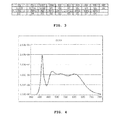
- FIG. 4 A spectrum of light emitted from the manufactured white LED is illustrated in FIG. 4 , and a CRI evaluation table is illustrated in FIG. 5 .
- FIG. 5 all CRI values of R1 to R15 were measured as 90 or more, and thus the CRI was greatly improved.
- a compound phosphor at 13.9 wt % and a sealing material at 86.1 wt % were mixed and coated on a blue LED chip with a size of 1000 ⁇ m ⁇ 500 ⁇ m and a peak wavelength of 446.9 nm.
- the compound phosphor was manufactured by mixing a first phosphor (BaSi 2 O 2 N 2 :Eu 2+ ) having a peak wavelength of 497 nm at 10.5 wt %, a second phosphor (Lu 3 Al 5 O 12 :Ce 3+ ) having a peak wavelength of 520 nm at 73.4 wt %, and a third phosphor (CaAlSiN 3 ) having a peak wavelength of 650 nm at 16.1 wt % into the sealing material.
- a ratio of the first phosphor to the second phosphor was 1:7.
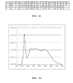
- FIG. 6 A spectrum of light of the manufactured white LED is illustrated in FIG. 6 , and a CRI evaluation table is illustrated FIG. 7 .
- all CRI values of R1 to R15 were 80 or more, and a value of R12 was highly increased to 99.
- a compound phosphor at 13.3 wt % and a sealing material at 86.7 wt % were mixed and coated on a blue LED chip with a size of 1000 ⁇ m ⁇ 500 ⁇ m and a peak wavelength of 456.5 nm.
- the compound phosphor was manufactured by mixing a first phosphor (BaSi 2 O 2 N 2 :Eu 2+ ) having a peak wavelength of 497 nm at 9.5 wt %, a second phosphor (Lu 3 Al 5 O 12 :Ce 3+ ) having a peak wavelength of 520 nm at 76.0 wt %, a third phosphor (CaAlSiN 3 ) having a peak wavelength of 650 nm at 14.5 wt % into the sealing material.
- a ratio of the first phosphor to the second phosphor was 1:8.
- FIG. 8 A spectrum of light emitted from the manufactured white LED is illustrated in FIG. 8 , and a CRI evaluation table is illustrated in FIG. 9 .
- a compound phosphor at 18.9 wt % and a sealing material at 81.1 wt % were mixed and coated on a blue LED chip with a size of 1000 ⁇ m ⁇ 500 ⁇ m and a peak wavelength of 448.7 nm.
- the compound phosphor was manufactured by mixing a first phosphor (BaSi 2 O 2 N 2 :Eu 2+ ) having a peak wavelength of 497 nm at 3.9 wt %, a second phosphor (Lu 3 Al 5 O 12 :Ce 3+ ) having a peak wavelength of 520 nm at 77.3 wt %, and a third phosphor (CaAlSiN 3 ) having a peak wavelength of 650 nm at 18.9 wt % into the sealing material.
- a ratio of the first phosphor to the second phosphor was 1:20, and the experiment was performed with a color temperature of 3000 k.
- FIG. 10 A spectrum of light of the manufactured white LED is illustrated in FIG. 10 , and a CRI evaluation table is illustrated FIG. 11 .
- a compound phosphor at 9.8 wt % and a sealing material at 90.2 wt % were mixed and coated on a blue LED chip with a size of 1000 ⁇ m ⁇ 500 ⁇ m and a peak wavelength of 448.7 nm.
- the compound phosphor was manufactured by mixing a first phosphor (BaSi 2 O 2 N 2 :Eu 2+ ) having a peak wavelength of 497 nm at 7.9 wt %, a second phosphor (Lu 3 Al 5 O 12 :Ce 3+ ) having a peak wavelength of 520 nm at 79.1 wt %, and a third phosphor (CaAlSiN 3 ) having a peak wavelength of 650 nm at 13.0 wt % into the sealing material.
- a ratio of the first phosphor to the second phosphor was 1:10, and the experiment was performed with a color temperature of 6700 k.
- FIG. 12 A spectrum of light emitted from the manufactured white LED is illustrated in FIG. 12 , and a CRI evaluation table is illustrated in FIG. 13 .
- a compound phosphor at 13.7 wt % and a sealing material at 86.3 wt % were mixed and coated on a blue LED chip with a size of 1000 ⁇ m ⁇ 500 ⁇ m and a peak wavelength of 456 nm.
- the compound phosphor is manufactured by mixing (Sr, Ba) 2 SiO 4 :Eu with a peak wavelength of 517 nm at 88.0 wt %, and (Si, Ca)AlSiN 3 : Eu with a peak wavelength of 630 nm at 12.0 wt % into the sealing material.
- a spectrum of light of the manufactured white LED is illustrated in FIG. 14
- a CRI evaluation table is illustrated FIG. 15 .
- a compound phosphor at 11.8 wt % and a sealing material at 88.2 wt % were mixed and coated on a blue LED chip with a size of 1000 ⁇ m ⁇ 500 ⁇ km and a peak wavelength of 453.8 nm.
- the compound phosphor was manufactured by mixing Lu 3 Al 5 O 12 : Ce 3+ with a peak wavelength of 520 nm at 69.3 wt %, Y 3 Al 5 O 12 : Ce 3+ with a peak wavelength of 546 nm at 17.3 wt %, and CaAlSiN 3 with a peak wavelength of 650 nm at 13.3 wt % into the sealing material.
- a spectrum of light of the manufactured white LED is illustrated in FIG. 16
- a CRI evaluation table is illustrated FIG. 17 .
- a compound phosphor at 12.0 wt % and a sealing material at 88.0 wt % were mixed and coated on a blue LED chip with a size of 1000 ⁇ m ⁇ 500 ⁇ m and a peak wavelength of 454.1 nm.
- the compound phosphor was manufactured by mixing a first phosphor (BaSi 2 O 2 N 2 :Eu 2+ ) having a peak wavelength of 497 nm at 3.3 wt %, a second phosphor (Lu 3 Al 5 O 12 :Ce 3+ ) having a peak wavelength of 520 nm at 83.3 wt %, and a third phosphor (CaAlSiN 3 ) having a peak wavelength of 650 nm at 6.7 wt % into the sealing material.
- a spectrum of light of the manufactured white LED is illustrated in FIG. 18 , and a CRI evaluation table is illustrated FIG. 19 .
- a compound phosphor at 13.3 wt % and a sealing material at 86.7 wt % were mixed and coated on a blue LED chip with a size of 1000 ⁇ m ⁇ 500 ⁇ m and a peak wavelength of 457.8 nm.
- the compound phosphor was manufactured by mixing a first phosphor (BaSi 2 O 2 N 2 : Eu 2+ ) having a peak wavelength of 497 nm at 7.8 wt %, a second phosphor (Lu 3 Al 5 O 12 : Ce 3+ ) having a peak wavelength of 520 nm at 77.7 wt %, and a third phosphor (CaAlSiN 3 ) having a peak wavelength of 650 nm at 14.5 wt % into the sealing material.
- a spectrum of light emitted from the manufactured white LED is illustrated in FIG. 20
- a CRI evaluation table is illustrated in FIG. 21 .
- the following table arranges CRI values of R12 according to a chip wavelength and a weight percent (wt %) of a phosphor of the above-described embodiments and comparative examples.
- each of the first embodiments 1 to 6 had a general CRI value and a special CRI value of 80 or more, and particularly, R12 was measured to have values of 80 or more, and thus an intensity of blue was increased. Accordingly, when the ratio of the first phosphor to the second phosphor is adjusted in the range of 1:7 to 1:15, a sense of blue may be increased when a white LED is used as a light.
- a value of R12 may be increased to 90 or more.
- the value of R12 is decreased compared to that of the fifth embodiment, the reason is that a color temperature of the fifth embodiment was 3000K and that of the sixth embodiment was 6700K. Accordingly, it can be seen that when the ratio of the first phosphor to the second phosphor is adjusted in the range of 1:7 to 1:10, the value of R12 may also be increased to 80 or more even when a color temperature is 6700K.
- a value of R12 may also be maintained at 80 or more when a chip has a long wavelength (456.5 nm). Accordingly, it can be seen that when the ratio of the first phosphor to the second phosphor is adjusted in the range of 1:7 to 1:8, the value of R12 may be maintained at 80 or more even when any one of a short wavelength LED chip and the long wavelength LED chip is used.
- the mass ratio of the first phosphor to the second phosphor is controlled in the range of 1:7 to 1:8, the value of R12 is maintained at 80 or more in an entire wavelength band of the blue LED chip (approximately in the range of 420 to 460 nm).
- a compound phosphor at 12.5 wt % and a sealing material at 87.5 wt % were mixed and coated on a blue LED chip with a size of 1000 ⁇ m ⁇ 500 ⁇ m and a dominant wavelength of 452 nm.
- the compound phosphor was manufactured by mixing a first phosphor (BaSi 2 O 2 N 2 : Eu 2+ ) having a peak wavelength of 497 nm at 0.68 wt %, a second phosphor (Lu 3 Al 5 O 12 : Ce 3+ ) having a peak wavelength of 520 nm at 10.1 wt %, and a third phosphor (CaAlSiN 3 ) having a peak wavelength of 650 nm at 1.72 wt % into the sealing material.
- a ratio of the first phosphor to the second phosphor was 1:15.
- FIG. 22 A spectrum of light emitted from the manufactured white LED is illustrated in FIG. 22 , and a CRI evaluation table is illustrated in FIG. 23 .
- a compound phosphor was formed of a first phosphor at 1.46 wt %, a second phosphor at 1.2 wt %, and a third phosphor at 2.24 wt %, a ratio of the first phosphor to the second phosphor was 1:7, and except for that everything else was the same as the seventh embodiment.
- FIG. 24 A spectrum of light emitted from the manufactured white LED is illustrated in FIG. 24 , and a CRI evaluation table is illustrated in FIG. 25 .
- a compound phosphor was formed of a first phosphor at 2.5 wt %, a second phosphor at 10.1 wt %, and a third phosphor at 2.1 wt %, a ratio of the first phosphor to the second phosphor was 1:4, and except for that everything else was the same as the seventh embodiment.
- FIG. 26 A spectrum of light emitted from the manufactured white LED is illustrated in FIG. 26 , and a CRI evaluation table is illustrated in FIG. 27 .
- a compound phosphor was formed of a first phosphor at 0.4 wt %, a second phosphor at 10.0 wt %, and a third phosphor at 1.6 wt %, a ratio of the first phosphor to the second phosphor was 1:25, and except for that everything else was the same as the seventh embodiment.
- FIG. 28 A spectrum of light emitted from the manufactured white LED is illustrated in FIG. 28 , and a CRI evaluation table is illustrated in FIG. 29 .
- FIG. 30 A spectrum of light emitted from the manufactured white LED is illustrated in FIG. 30 , and a CRI evaluation table is illustrated in FIG. 31 .
- a compound phosphor at 11.2 wt % and a sealing material at 88.8 wt % were mixed and coated on a blue LED chip with a size of 1000 ⁇ m ⁇ 500 ⁇ m and a dominant wavelength of 457 nm.
- FIG. 32 A spectrum of light emitted from the manufactured white LED is illustrated in FIG. 32 , and a CRI evaluation table is illustrated in FIG. 33 .
- FIG. 34 A spectrum of light emitted from the manufactured white LED is illustrated in FIG. 34 , and a CRI evaluation table is illustrated in FIG. 35 .
- FIG. 36 A spectrum of light emitted from the manufactured white LED is illustrated in FIG. 36 , and a CRI evaluation table is illustrated in FIG. 37 .
- a compound phosphor was formed of a first phosphor at 2.6 wt %, a second phosphor at 7.9 wt %, and a third phosphor at 1.9 wt %, a ratio of the first phosphor to the second phosphor was 1:3, and except for that everything else was the same as the tenth Embodiment.
- FIG. 38 A spectrum of light emitted from the manufactured white LED is illustrated in FIG. 38 , and a CRI evaluation table is illustrated in FIG. 39 .
- Table 2 is a table which arranges CRI values of R12 according to a chip wavelength and a wt % of a phosphor of above-described embodiments and comparative examples.
- the CRI value may be maintained at 80 or more.
- the ratio of the first phosphor and the second phosphor is greater than 1:10 or less than 1:3, the value of R12 is decreased to under 80.
- the general CRI and the special CRI may be maintained at 80 or more regardless of a short wavelength chip or a long wavelength chip, and particularly the value of R12 may be increased to 80 or more.
Landscapes
- Chemical & Material Sciences (AREA)
- Engineering & Computer Science (AREA)
- Materials Engineering (AREA)
- Organic Chemistry (AREA)
- Inorganic Chemistry (AREA)
- Led Device Packages (AREA)
- Luminescent Compositions (AREA)
- Non-Portable Lighting Devices Or Systems Thereof (AREA)
Abstract
Description
λ1<λ2<λ3<λ4 [Expression 1]
Mx(1-p)SiyOzN(2x+4y-2z)/3;Eu2+ [Equation 1]
BaSix(O,Cl)Nx:Eu2+ (0<x≦2) [Equation 3]
M3Al5O12:Ce3+ [Equation 2]
(Lux,Ce1-x)3Al5O12 (0<X<1) [Equation 4]
λ1<λ2<λ3<λ [Expression 1]
| TABLE 1 | ||||||
| Chip | First | Second | Third | |||
| Wave- | Phos- | Phos- | Phos- | First Phos- | ||
| length | phor | phor | phor | phor/Second | CRI | |
| (nm) | (wt %) | (wt %) | (wt %) | Phosphor | R12 | |
| First | 446.3 | 5.4 | 80.7 | 6.9 | 1:14 | 85 |
| Embodi- | ||||||
| ment | ||||||
| Second | 446.3 | 7.7 | 76.9 | 15.4 | 1:9.98 | 90 |
| Embodi- | ||||||
| ment | ||||||
| Third | 446.9 | 10.5 | 73.4 | 16.1 | 1:6.99 | 99 |
| Embodi- | ||||||
| ment | ||||||
| Fourth | 456.5 | 9.5 | 76.0 | 14.5 | 1:8 | 80 |
| Embodi- | ||||||
| ment | ||||||
| Fifth | 448.7 | 3.9 | 77.3 | 18.9 | 1:19 | 97 |
| Embodi- | ||||||
| ment | ||||||
| Sixth | 448.7 | 7.9 | 79.1 | 13.0 | 1:10 | 81 |
| Embodi- | ||||||
| ment | ||||||
| Compar- | 456.0 | — | 88.0 | 12.0 | — | 67 |
| ative | ||||||
| example | ||||||
| 1 | ||||||
| Compar- | 453.8 | 69.3 | 17.3 | 13.3 | — | 66 |
| ative | ||||||
| Example | ||||||
| 2 | ||||||
| Compar- | 454.1 | 3.3 | 83.3 | 6.7 | 1:25 | 75 |
| ative | ||||||
| Example | ||||||
| 3 | ||||||
| Compar- | 457.8 | 7.8 | 77.7 | 14.5 | 1:10 | 78 |
| ative | ||||||
| Example | ||||||
| 4 | ||||||
| TABLE 2 | ||||||
| Chip | First | Second | Third | |||
| Wave- | Phos- | Phos- | Phos- | First Phos- | ||
| length | phor | phor | phor | phor/Second | CRI | |
| nm | wt % | wt % | wt % | Phosphor | R12 | |
| Seventh | 452 | 0.68 | 10.1 | 1.72 | 1:15 | 85 |
| Embodi- | ||||||
| ment | ||||||
| Eighth | 452 | 1.46 | 10.2 | 2.24 | 1:7 | 99 |
| Embodi- | ||||||
| ment | ||||||
| Ninth | 452 | 2.5 | 10.1 | 2.1 | 1:4 | 88 |
| Embodi- | ||||||
| ment | ||||||
| Tenth | 457 | 1.1 | 8.8 | 1.3 | 1:8 | 80 |
| Embodi- | ||||||
| ment | ||||||
| Eleventh | 457 | 1.3 | 8.8 | 1.7 | 1:7 | 82.7 |
| Embodi- | ||||||
| ment | ||||||
| Compar- | 452 | 0.4 | 10.0 | 1.6 | 1:25 | 75 |
| ative | ||||||
| Example | ||||||
| 5 | ||||||
| Compar- | 452 | 3.3 | 9.8 | 2.3 | 1:3 | 87 |
| ative | ||||||
| Example | ||||||
| 6 | ||||||
| Compar- | 457 | 0.85 | 8.5 | 1.05 | 1:10 | 78 |
| ative | ||||||
| Example | ||||||
| 7 | ||||||
| Compar- | 457 | 2.6 | 7.9 | 1.9 | 1:3 | 79.4 |
| ative | ||||||
| Example | ||||||
| 8 | ||||||
Claims (6)
Mx(1-p)SiyOzN(2x+4y-2z)/3;Eu2+
Applications Claiming Priority (5)
| Application Number | Priority Date | Filing Date | Title |
|---|---|---|---|
| KR10-2013-0135280 | 2013-11-08 | ||
| KR20130135280 | 2013-11-08 | ||
| KR1020140049845A KR101795740B1 (en) | 2013-11-08 | 2014-04-25 | Light emitting device |
| KR10-2014-0049845 | 2014-04-25 | ||
| PCT/KR2014/003664 WO2015068916A1 (en) | 2013-11-08 | 2014-04-25 | Light-emitting device |
Publications (2)
| Publication Number | Publication Date |
|---|---|
| US20160293808A1 US20160293808A1 (en) | 2016-10-06 |
| US9837585B2 true US9837585B2 (en) | 2017-12-05 |
Family
ID=53390201
Family Applications (1)
| Application Number | Title | Priority Date | Filing Date |
|---|---|---|---|
| US15/035,378 Expired - Fee Related US9837585B2 (en) | 2013-11-08 | 2014-04-25 | Light emitting device |
Country Status (3)
| Country | Link |
|---|---|
| US (1) | US9837585B2 (en) |
| JP (2) | JP2017502528A (en) |
| KR (1) | KR101795740B1 (en) |
Cited By (1)
| Publication number | Priority date | Publication date | Assignee | Title |
|---|---|---|---|---|
| US11133441B2 (en) | 2018-09-28 | 2021-09-28 | Nichia Corporation | Light emitting device and lighting fixture provided with the same |
Families Citing this family (5)
| Publication number | Priority date | Publication date | Assignee | Title |
|---|---|---|---|---|
| KR102478491B1 (en) * | 2015-12-30 | 2022-12-16 | 엘지디스플레이 주식회사 | Organic Light Emitting Diode Display Device And Method Of Fabricating The Same |
| US10177287B1 (en) * | 2017-09-19 | 2019-01-08 | Eie Materials, Inc. | Gamut broadened displays with narrow band green phosphors |
| JP2019062173A (en) * | 2017-09-26 | 2019-04-18 | パナソニックIpマネジメント株式会社 | Luminaire apparatus and light-emitting device |
| JP7303437B2 (en) * | 2018-09-28 | 2023-07-05 | 日亜化学工業株式会社 | Light-emitting device and lamp equipped with the same |
| JP7348521B2 (en) * | 2019-12-24 | 2023-09-21 | 日亜化学工業株式会社 | light emitting device |
Citations (8)
| Publication number | Priority date | Publication date | Assignee | Title |
|---|---|---|---|---|
| US6621211B1 (en) | 2000-05-15 | 2003-09-16 | General Electric Company | White light emitting phosphor blends for LED devices |
| US20050156496A1 (en) * | 2003-09-18 | 2005-07-21 | Suguru Takashima | Light emitting device |
| WO2008020541A1 (en) | 2006-08-14 | 2008-02-21 | Fujikura Ltd. | Light emitting device and illumination device |
| US20100157572A1 (en) | 2008-12-18 | 2010-06-24 | Foxsemicon Integrated Technology, Inc. | Illuminating apparatus with phosphor films |
| US8054970B2 (en) | 2004-07-22 | 2011-11-08 | Canon Kabushiki Kaisha | Image forming apparatus, image forming method, information processing apparatus and information processing method |
| US20120056528A1 (en) | 2010-09-02 | 2012-03-08 | Kabushiki Kaisha Toshiba | Fluorescent substance and light-emitting device employing the same |
| JP2013047347A (en) | 2010-09-02 | 2013-03-07 | Toshiba Corp | Phosphor and light-emitting device using the same |
| KR20130057354A (en) | 2011-11-23 | 2013-05-31 | 삼성전자주식회사 | White light emitting diode and lighting apparatus including the same |
Family Cites Families (8)
| Publication number | Priority date | Publication date | Assignee | Title |
|---|---|---|---|---|
| US7094362B2 (en) * | 2003-10-29 | 2006-08-22 | General Electric Company | Garnet phosphor materials having enhanced spectral characteristics |
| US7250715B2 (en) * | 2004-02-23 | 2007-07-31 | Philips Lumileds Lighting Company, Llc | Wavelength converted semiconductor light emitting devices |
| JP4128564B2 (en) * | 2004-04-27 | 2008-07-30 | 松下電器産業株式会社 | Light emitting device |
| JPWO2006077740A1 (en) * | 2004-12-28 | 2008-06-19 | 日亜化学工業株式会社 | Light emitting device and manufacturing method thereof |
| JP2007088299A (en) * | 2005-09-22 | 2007-04-05 | Mitsubishi Chemicals Corp | LIGHT EMITTING DEVICE, LIGHTING DEVICE USING SAME, AND IMAGE DISPLAY DEVICE |
| JP4930649B1 (en) * | 2011-02-25 | 2012-05-16 | 三菱化学株式会社 | Halophosphate phosphor and white light emitting device |
| US9109762B2 (en) * | 2011-04-22 | 2015-08-18 | Kabushiki Kaisha Toshiba | White light source and white light source system including the same |
| US8921875B2 (en) * | 2011-05-10 | 2014-12-30 | Cree, Inc. | Recipient luminophoric mediums having narrow spectrum luminescent materials and related semiconductor light emitting devices and methods |
-
2014
- 2014-04-25 JP JP2016553185A patent/JP2017502528A/en active Pending
- 2014-04-25 US US15/035,378 patent/US9837585B2/en not_active Expired - Fee Related
- 2014-04-25 KR KR1020140049845A patent/KR101795740B1/en not_active Expired - Fee Related
-
2018
- 2018-12-20 JP JP2018238429A patent/JP2019054286A/en active Pending
Patent Citations (15)
| Publication number | Priority date | Publication date | Assignee | Title |
|---|---|---|---|---|
| US6621211B1 (en) | 2000-05-15 | 2003-09-16 | General Electric Company | White light emitting phosphor blends for LED devices |
| US20040007961A1 (en) | 2000-05-15 | 2004-01-15 | General Electric Company | White light emitting phosphor blends for LED devices |
| US6939481B2 (en) | 2000-05-15 | 2005-09-06 | General Electric Company | White light emitting phosphor blends for LED devices |
| US20050156496A1 (en) * | 2003-09-18 | 2005-07-21 | Suguru Takashima | Light emitting device |
| JP2005340748A (en) | 2003-09-18 | 2005-12-08 | Nichia Chem Ind Ltd | Light emitting device |
| US8054970B2 (en) | 2004-07-22 | 2011-11-08 | Canon Kabushiki Kaisha | Image forming apparatus, image forming method, information processing apparatus and information processing method |
| US20090146549A1 (en) * | 2006-08-14 | 2009-06-11 | Fujikura Ltd. | Light emitting device and illumination device |
| WO2008020541A1 (en) | 2006-08-14 | 2008-02-21 | Fujikura Ltd. | Light emitting device and illumination device |
| JP4963705B2 (en) | 2006-08-14 | 2012-06-27 | 株式会社フジクラ | LIGHT EMITTING DEVICE AND LIGHTING DEVICE |
| US20100157572A1 (en) | 2008-12-18 | 2010-06-24 | Foxsemicon Integrated Technology, Inc. | Illuminating apparatus with phosphor films |
| US8162506B2 (en) | 2008-12-18 | 2012-04-24 | Foxsemicon Integrated Technology, Inc. | Illuminating apparatus with phosphor films |
| US20120056528A1 (en) | 2010-09-02 | 2012-03-08 | Kabushiki Kaisha Toshiba | Fluorescent substance and light-emitting device employing the same |
| JP2013047347A (en) | 2010-09-02 | 2013-03-07 | Toshiba Corp | Phosphor and light-emitting device using the same |
| US8471459B2 (en) | 2010-09-02 | 2013-06-25 | Kabushiki Kaisha Toshiba | Fluorescent substance and light-emitting device employing the same |
| KR20130057354A (en) | 2011-11-23 | 2013-05-31 | 삼성전자주식회사 | White light emitting diode and lighting apparatus including the same |
Non-Patent Citations (1)
| Title |
|---|
| Japanese Office Action dated Jan. 10, 2017. |
Cited By (1)
| Publication number | Priority date | Publication date | Assignee | Title |
|---|---|---|---|---|
| US11133441B2 (en) | 2018-09-28 | 2021-09-28 | Nichia Corporation | Light emitting device and lighting fixture provided with the same |
Also Published As
| Publication number | Publication date |
|---|---|
| JP2017502528A (en) | 2017-01-19 |
| KR101795740B1 (en) | 2017-11-08 |
| US20160293808A1 (en) | 2016-10-06 |
| KR20150053688A (en) | 2015-05-18 |
| JP2019054286A (en) | 2019-04-04 |
Similar Documents
| Publication | Publication Date | Title |
|---|---|---|
| US10700244B2 (en) | System and method for selected pump LEDs with multiple phosphors | |
| US7897987B2 (en) | Light-emitting device including light-emitting diode and stacked light-emitting phosphor layers | |
| CN102378801B (en) | Luminescent converter for a phosphor- enhanced light source comprising organic and inorganic phosphors | |
| KR101265094B1 (en) | White light emitting diode and method for producing the same | |
| US9837585B2 (en) | Light emitting device | |
| JP5749201B2 (en) | White light emitting device | |
| US20140354146A1 (en) | Luminaire | |
| CN1938870A (en) | Phosphors and mixtures thereof for LEDs | |
| US8519611B2 (en) | Hybrid illumination system with improved color quality | |
| KR20180090002A (en) | Light emitting diode package | |
| KR100799839B1 (en) | Phosphor mixture for wavelength conversion and white light emitting device using the same | |
| JP6552516B2 (en) | Phosphor high concentration filled LED package | |
| TWI595803B (en) | White light illumination system | |
| KR20190107181A (en) | Low CCT LED Design Using PFS Phosphors | |
| KR101706600B1 (en) | White Light Emitting Device with High Color Rendering Index | |
| KR101652258B1 (en) | White Light Emitting Device with High Color Rendering Index | |
| KR101196207B1 (en) | Green light-emitting diode by phosphor | |
| KR101855391B1 (en) | White Light Emitting Device with High Color Rendering Index | |
| KR20150051780A (en) | Light emitting module | |
| KR102637411B1 (en) | Phosphor emitting red light and light emitting device using the same | |
| US20090189168A1 (en) | White Light Emitting Device | |
| KR101809098B1 (en) | Light emitting device | |
| US20120025223A1 (en) | Led lighting device with high colour re-producibility | |
| US9475987B2 (en) | Yellow light emitting phosphor and light emitting device package using the same | |
| JP2025533384A (en) | Light-emitting element and lighting fixture having the same |
Legal Events
| Date | Code | Title | Description |
|---|---|---|---|
| AS | Assignment |
Owner name: LUMIMICRO CORP. LTD., KOREA, REPUBLIC OF Free format text: ASSIGNMENT OF ASSIGNORS INTEREST;ASSIGNOR:LEE, SANG IL;REEL/FRAME:038972/0206 Effective date: 20160523 |
|
| STCF | Information on status: patent grant |
Free format text: PATENTED CASE |
|
| FEPP | Fee payment procedure |
Free format text: MAINTENANCE FEE REMINDER MAILED (ORIGINAL EVENT CODE: REM.); ENTITY STATUS OF PATENT OWNER: SMALL ENTITY |
|
| FEPP | Fee payment procedure |
Free format text: SURCHARGE FOR LATE PAYMENT, SMALL ENTITY (ORIGINAL EVENT CODE: M2554); ENTITY STATUS OF PATENT OWNER: SMALL ENTITY |
|
| MAFP | Maintenance fee payment |
Free format text: PAYMENT OF MAINTENANCE FEE, 4TH YR, SMALL ENTITY (ORIGINAL EVENT CODE: M2551); ENTITY STATUS OF PATENT OWNER: SMALL ENTITY Year of fee payment: 4 |
|
| FEPP | Fee payment procedure |
Free format text: MAINTENANCE FEE REMINDER MAILED (ORIGINAL EVENT CODE: REM.); ENTITY STATUS OF PATENT OWNER: SMALL ENTITY |
|
| LAPS | Lapse for failure to pay maintenance fees |
Free format text: PATENT EXPIRED FOR FAILURE TO PAY MAINTENANCE FEES (ORIGINAL EVENT CODE: EXP.); ENTITY STATUS OF PATENT OWNER: SMALL ENTITY |
|
| STCH | Information on status: patent discontinuation |
Free format text: PATENT EXPIRED DUE TO NONPAYMENT OF MAINTENANCE FEES UNDER 37 CFR 1.362 |
|
| FP | Lapsed due to failure to pay maintenance fee |
Effective date: 20251205 |