EP2697002B1 - Control method for a mill train - Google Patents
Control method for a mill train Download PDFInfo
- Publication number
- EP2697002B1 EP2697002B1 EP12719000.7A EP12719000A EP2697002B1 EP 2697002 B1 EP2697002 B1 EP 2697002B1 EP 12719000 A EP12719000 A EP 12719000A EP 2697002 B1 EP2697002 B1 EP 2697002B1
- Authority
- EP
- European Patent Office
- Prior art keywords
- strip
- rolling
- model
- predicted
- roll stand
- Prior art date
- Legal status (The legal status is an assumption and is not a legal conclusion. Google has not performed a legal analysis and makes no representation as to the accuracy of the status listed.)
- Active
Links
Images


Classifications
-
- B—PERFORMING OPERATIONS; TRANSPORTING
- B23—MACHINE TOOLS; METAL-WORKING NOT OTHERWISE PROVIDED FOR
- B23P—METAL-WORKING NOT OTHERWISE PROVIDED FOR; COMBINED OPERATIONS; UNIVERSAL MACHINE TOOLS
- B23P17/00—Metal-working operations, not covered by a single other subclass or another group in this subclass
-
- B—PERFORMING OPERATIONS; TRANSPORTING
- B21—MECHANICAL METAL-WORKING WITHOUT ESSENTIALLY REMOVING MATERIAL; PUNCHING METAL
- B21B—ROLLING OF METAL
- B21B37/00—Control devices or methods specially adapted for metal-rolling mills or the work produced thereby
- B21B37/58—Roll-force control; Roll-gap control
-
- B—PERFORMING OPERATIONS; TRANSPORTING
- B21—MECHANICAL METAL-WORKING WITHOUT ESSENTIALLY REMOVING MATERIAL; PUNCHING METAL
- B21B—ROLLING OF METAL
- B21B2261/00—Product parameters
- B21B2261/20—Temperature
- B21B2261/21—Temperature profile
-
- B—PERFORMING OPERATIONS; TRANSPORTING
- B21—MECHANICAL METAL-WORKING WITHOUT ESSENTIALLY REMOVING MATERIAL; PUNCHING METAL
- B21B—ROLLING OF METAL
- B21B2271/00—Mill stand parameters
- B21B2271/02—Roll gap, screw-down position, draft position
Definitions
- the present invention relates to a control method for a rolling line, wherein an actuator acting on a first stand of the rolling line is controlled during the rolling of strip sections taking into account at least one control parameter.
- the present invention further relates to a computer program comprising machine code which can be processed directly by a control computer for a rolling train and whose execution by the control computer causes the control computer to execute such a control method.
- the present invention further relates to a rolling table control computer programmed to execute such a control method in operation.
- the present invention further relates to a rolling train for rolling a belt, which comprises at least a first rolling mill and is equipped with such a control computer.
- Temperature variations across the width and length of the belt can lead to significant disturbances in the rolling operation. Due to the changing material hardness, there are variations in the rolling force, which in turn can lead to other skeletal reactions, which in turn have a change in the nip profile result. Examples of such framework reactions are roll flattening, roll deflection, and scaffold feathering. In addition, there is a change in the Walzenbombtechnik by the contact of the work rolls with the different warm band. This also has an influence on the geometry of the roll gap. If such changes in the roll gap profile are not taken into account, thickness, profile and flatness errors are the result.
- the AGC can not respond to variations in the temperature profile across the bandwidth.
- an asymmetry in the material strength for example, caused by a temperature wedge
- associated asymmetry in the framework reaction is not taken into account.
- a variation of the Walzenbombtechnik is not detectable or only with delay.
- the precontrol of the rolling stands of a multi-stand rolling train by means of the rolling force measurement in the first rolling stand of the rolling train is inherently not applicable to a single-storey street.
- this problem occurs in combined casting and rolling mills, where there are no or limited compensation for variations in temperature in the belt, so that temperature profiles (over the length and / or the bandwidth) until reaching the roll stand or the rolling stands have not compensated. Even with hot strip mill, it can lead to variations in temperature, for example, by the so-called skidmarks or uneven heating of the slab in the oven.
- a pure determination of the temperature behavior and possibly also the phase transformation of the strip sections is carried out with the aim of being able to suitably set a strip heating and / or a strip cooling.
- a utilization of the determined temperature in the context of the rolling process as such is in the DE 101 56 008 A1 not provided.
- a control method for a rolling train is known in which for strip sections of a strip in front of a first rolling stand of the rolling train in each case a temperature is determined which comprise the band sections.
- a temperature is determined which comprise the band sections.
- the object of the present invention is to provide ways by which the temperature profile of the belt during rolling of the belt can be taken into account in a particularly advantageous manner.
- the temperature profile of the strip should be taken into account in the profile adjustment of the roll gap.
- control method having the features of claim 1.
- Advantageous embodiments of the control method according to the invention are the subject of the dependent claims 2 to 11.
- the adjusting device for influencing the roll gap profile can be designed as required.
- a roll back bending and / or a roll displacement come into question.
- the adjusting device comprises a roll cooling device.
- the roll cooling device can be controlled in a spatially resolved manner, in particular in the bandwidth direction.
- control method with a second prognosis horizon is also carried out for a second rolling stand of the rolling train downstream of the first rolling stand.
- the strip sections in the first rolling stand are rolled from a first inlet thickness to a first outlet thickness and in the second rolling stand from a second inlet thickness to a second outlet thickness.
- first outlet thickness and / or the second inlet thickness are determined band-specific. As a result of this procedure, load redistribution between the first and the second roll stand can take place, in particular during ongoing rolling operation.
- the prognosis horizon for the second roll stand can be determined as required, but it must be dimensioned - analogous to the forecast horizon for the first roll stand - such that it corresponds to several strip sections, ie during the forecast horizon for the second rolling mill stand in the second rolling stand to be rolled.
- the second prognosis horizon is dimensioned such that during the second prognosis horizon several strip sections are rolled both in the first and in the second rolling stand.
- the forecast horizons for the first and the second roll stand can be dimensioned such that the difference of the forecast horizon corresponds to the time it takes for a strip section to pass from the first roll stand to the second roll stand.
- the forecast horizons can be placed, so to speak, at the same location in front of the first mill stand.
- the temperatures for the band sections may be sufficient to forecast the temperatures for the band sections as scalar quantities. Often, however, it is advantageous if the predicted by means of the tape model temperatures of the band sections in the bandwidth direction are spatially resolved. Preferably, in this case, the temperatures determined for the strip sections are already spatially resolved in the bandwidth direction.
- control computer causes the control computer to execute a control method according to the invention.
- control computer having the features of claim 13.
- the control computer is programmed such that it carries out an inventive control method during operation.
- a rolling train for rolling a belt which comprises at least a first roll stand, is equipped with a control computer programmed according to the invention.
- a rolling mill for rolling a strip 1 has a first rolling stand 2.
- the first rolling stand 2 may be the only rolling stand of the rolling train. Alternatively, further rolling mills may be present.
- the band 1 is usually a metal band, for example a steel, aluminum, magnesium or copper band. Other metals and metal alloys are also possible.
- the rolling train and thus also the first rolling stand 2 are controlled by a control computer 3.
- the control computer 3 is programmed with a computer program 4.
- the computer program 4 comprises machine code 5, which can be processed directly by the control computer 3.
- the processing of the machine code 5 by the control computer 3 - ie the operation of the control computer 3 - causes the control computer 3 at least one - possibly even more - performs the control method, which will be described below in connection with FIGS. 2 to 19 be explained in more detail.
- FIG. 2 takes the control computer 3 in a step S1 for band sections 6 of the belt 1 each a temperature T opposite. It is possible (and even common) for the temperatures T of the band sections 6 to be determined according to FIG FIG. 1 be detected by means of a temperature measuring device 7 metrologically. Alternatively, another determination - in particular calculation - done.
- the determination of the step S1 takes place for a location x which is located in front of the first rolling stand 2.
- the temperature T is thus characteristic of the respective temperature T of the respective band section 6 at a time at which the corresponding band section 6 is still in front of the first rolling stand 2.
- the control computer 3 implemented due to the programming with the computer program 4, inter alia, a band model 8.
- the band model 8 models by means of mathematical-physical equations at least the temperature behavior of the belt 1.
- a heat equation is achieved.
- the internal heat conduction within the band 1 as well as the interaction of the band 1 with its environment are taken into account, for example the interaction with cooling and heating devices, a scale scrubber, the contact with transport rollers.
- a phase transformation equation can also be achieved.
- An advantageous heat equation is for example in the DE 101 29 565 A1 or the same content US Pat. No. 6,860,950 B2 described.
- An advantageous phase conversion equation is for example in the EP 1 711 868 B1 or the same content US Pat. No. 7,865,341 B2 described.
- 8 other models can be included in the band model.
- the control computer 3 thus predicts the temperature of the belt sections 6 for the time of rolling of the respective belt section 6 in the first rolling stand 2 in a step S2 on the basis of the determined temperatures T.
- the predicted temperature is used to distinguish it from the determined temperature T. provided with the reference T '.
- the forecast is made with a forecast horizon PH1, hereinafter referred to as the first forecast horizon PH1.
- the first forecast horizon PH1 corresponds to the number of time steps by which the belt model 8 predicts the temperature T ', during each time step one strip section 6 in the first rolling stand 2 is rolled.
- the first forecast horizon PH1 comprises a single time step.
- a minimal forecast horizon PHmin is thus determined by the fact that the prediction of the temperature of the band sections 6 leads by a single time step.
- a single band section 6 is rolled, namely the immediately preceding band section 6.
- the first prognosis horizon PH1 is however dimensioned in this way in that during the first forecasting horizon PH1 in the first rolling stand 2 several band sections 6 are rolled, for example, five, eight, ten or more band sections. 6
- control computer 3 determines, using the predicted temperatures T 'of the belt sections 6, at least one control parameter P for rolling the respective belt section 6 in the first rolling stand 2.
- control computer 3 controls an actuating device 10.
- the control device 10 acts on the first rolling stand 2.
- the control of the adjusting device 10 takes place during the rolling of the respective band section 6, taking into account the control parameter P determined for the band section 6 currently to be rolled.
- a specific temperature T is determined for a specific band section 6, for example by measurement (step S1).
- the corresponding belt section 6 is tracked away during its transport through the mill train.
- the temperature T 'expected for the corresponding band section 6 is continuously included (step S2), the model-based temperature forecasting being at least one time step ahead of the location of the corresponding band section 6.
- the immediately preceding band section 6 is rolled-the control parameter P for the considered band section 6 is determined.
- the control parameter P is therefore known to the control computer 3 in good time, so that the control computer 3 can take into account the control parameter P in the control of the setting device 10 when the considered belt section 6 is rolled in the first rolling stand 2.
- the procedure of FIG. 2 is usually performed clocked, for example, with a time cycle between 0.1 second and 0.5 seconds, usually about 0.2 seconds to 0.3 seconds. With each time clock, the temperature T is determined for a new band section 6 and so the control computer 3 known. The temperature forecast is then model-based.
- the control computer 3 also requires the predicted temperatures T 'and possibly also other properties of other belt sections 6 and / or predicted properties of the first rolling stand 2. As far as the belt sections 6 to be rolled according to the considered belt section 6 are concerned, their temperatures and properties are known to the control computer 3 if they are within the first prognosis horizon PH1. For example, the control computer 3 is already aware of the expected temperatures T 'of the seven subsequent belt sections 6 at a first forecast horizon PH1 of eight belt sections 6 at the time at which a specific belt section 6 determines its temperature T.
- the predicted temperatures T 'of the eight belt sections 6 located in front of the first rolling mill 2 are known at all times. Therefore, they can be considered for the determination of the control parameter P for the strip section 6, which is rolled in the first stand 2 next.
- the temperatures and properties of the control computer 3 from the past are known.
- the first prognosis horizon PH1 is dimensioned such that several band sections 6 are rolled in the first rolling stand 2 during the first prognosis horizon PH1.
- the first prognosis horizon PH1 corresponds to eight band sections 6.
- this dimensioning is only illustrative, so is not limiting to forcibly eight band sections 6 to understand.
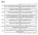
- step S2 is merely to mention that in the context of step S2 of FIG. 3 the step S2 with the first forecast horizon PH1 of a plurality of - purely exemplary eight - band sections 6 is executed.
- step S2 of FIG. 3 the corresponding temperatures T 'are predicted for all belt sections 6, which are up to eight belt sections 6 in front of the first rolling mill 2 at the time considered.
- Step S3 of FIG. 2 is in FIG. 3 implemented by steps S6 to S10.
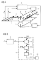
- the adjusting device 10 is formed such that with her the profile of the roll gap - ie the distance of the work rolls 9 of the first stand 2 seen from each other across the width - can be adjusted.
- the adjusting device 10 may be designed for this purpose as a roller pushing device and / or as a roller bending device.
- the adjusting device 10 may comprise a roller cooling device 11, possibly alone, alternatively in addition to a roller pushing and / or roller bending device.
- the roll cooling device 11 can as shown in FIG FIG. 4 be controlled in particular in the bandwidth direction spatially resolved.
- step S6 a manipulated variable course S (t) for the actuator 10 attached.
- the manipulated variable course S (t) is set for the first prognosis horizon PH1 - ie the considered band section 6 and the seven band sections 6 following the band section 6 under consideration.
- the profile of the roll gap is influenced in accordance with the nature of the adjusting device 10.
- the thermal crowning of the work rolls 9 can be adjusted, for example, by the roll cooling device 11.
- the manipulated variable optimizer 12 is a software block implemented by the control computer 3. It includes, inter alia, a roll stand model 13.
- the roll stand model 13 models in particular the thermal crowning of the work rolls 9 and the wear of the work rolls 9, which results from the contact of the work rolls 9 with the strip 1.
- the roll stand model 13 further models the influence of the control variable course S (t) on the roll gap, for example the influence of the roll cooling device 11 on the thermal crowning.
- the rolling stand model 13 predicts in step S8 as output variable a temporal roll gap profile profile W (t).
- the rolling stand model 13 thus determines in step S8 for each lying within the first forecasting horizon PH1 band section 6, the roll gap profile W, that for the respective Band section 6 results.
- the roll stand model 13 determines the roll gap profile profile W (t) using the control variable curve S (t) supplied to it and the predicted temperatures T 'of the strip sections 6.
- the nip profile profile W (t) is determined according to FIG. 3 and 5 evaluated in an evaluator 14 and optimized by the evaluator 14 in step S9.
- a renewed call of the roll stand model 13 can take place after a modification of the scheduled manipulated variable profile S (t). This is in the FIG. 5 indicated by dashed lines.
- the determined roll gap profile profile W (t) is compared with a desired profile profile W * (t).
- the desired profile profile W * (t) can be constant. Regardless of whether the desired profile profile W * (t) is constant or not, the primary aim of the optimization is to ensure the flatness of the band 1. Subordinated should be rolled as far as possible a uniform profile as possible.
- the temperature detection is according to FIG. 4 coupled with a band thickness detection and / or a band profile detection.
- the desired profile W * for the respective band section 6 can be determined in a profile and flatness model on the basis of the detected strip thickness or the detected strip thickness profile.
- the optimized manipulated variable profile S (t) is determined according to FIG. 5 a selector 15 is supplied.
- the selector 15 selects in step S10 the current value of the optimized manipulated variable curve S (t), ie the value of the optimized manipulated variable curve S (t), which was determined for the strip section 6 to be rolled next.
- This value S corresponds to the control parameter P of the step S4 and is the actuator 10 in step S4 of FIG. 3 specified as a manipulated variable.
- the manipulated variable optimizer 12 in the context of FIG. 3 determined optimized control curve S (t) "forgets". However, the manipulated variable optimizer 12 preferably "remembers" the optimized manipulated variable profile S (t) and uses it for the matching band sections 6 as an applied manipulated variable curve S (t) for the next operating cycle, ie when the next strip section 6 is treated.
- FIG. 6 is a modification of FIG. 3 .
- FIG. 7 a modification of FIG. 5 , In the following, therefore, only the differences from these FIG will be discussed in more detail.
- step S11 the temperatures T 'predicted by the belt model 8 are fed to a rolling force model 16.
- step S12 the rolling forces F are predicted in step S12 using the predicted temperatures T 'for the respective belt sections 6.
- the rolling force model 16 thus determines, for each band section 6 to be rolled within the first prognosis horizon PH1, which rolling force F is required in order to roll the corresponding band section 6 from a first inlet thickness di1 to a desired first outlet thickness do1.
- the additional sizes required for this purpose such as the chemical composition of the strip 1, the first inlet thickness di1, the strip width b, the rolling speed v, inlet and outlet sides, etc., are likewise fed to the rolling force model 16.
- step S13 the manipulated variable optimizer 12 - as in step S7 of FIG. 3 also - the predicted temperatures T 'and the scheduled Control variable course S (t) supplied.
- the predicted rolling forces F are fed to the manipulated variable optimizer 12 in step S13.
- step S14 the manipulated variable optimizer 12 predicts in the context of its roll stand model 13 analogously to step S8 of FIG FIG. 3 for the band sections 6 to be rolled in the first rolling stand 2 in the first prognostic horizon PH1, the respective rolling gap profile W is additionally taken into account in the step S14 in the prognostication of the roll gap profile profile W (t).
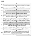
- the band model 8 according to FIG. 9 are the steps S2, S11 and S12 of FIG. 6 replaced by steps S16 to S18.
- the band model 8 according to FIG. 9 a temperature model 17 and a material model 18.
- the temperatures T 'of the band sections 6 are predicted in step S16 - as previously in step S2 by the band model 8.
- a further material property is predicted by means of the material model 18, which is expected for the respective strip sections 6 to be rolled in the first rolling stand 2 during the first forecasting horizon PH1 during the rolling of the respective strip section 6 in the first rolling stand 2.
- the further material property is - of course - different from the temperature T ', but has an influence on the rolling force required for rolling the respective strip section 6.
- the further material property may be a phase transformation degree, a material consolidation, a recrystallization or act a microstructure.
- a unidirectional or bidirectional coupling between the temperature development and the development of the further material property can exist.
- the course of the temperature of the considered band section 6 during the first prediction horizon PH1 determined, then determines the determined temporal temperature profile of the material model 18 and finally determined on the basis of the material model 18, the further material property.
- step S17 the rolling force model 16 - in addition to the values and sizes mentioned in step S11 - are also supplied with the corresponding further material properties for the corresponding strip sections 6.
- step S18 the rolling force model 16 predicts the required rolling forces F with additional consideration of the further material properties as well.
- control computer 3 takes into account the procedure of the.
- the further material properties influence the predicted rolling forces F, this in turn on the nip profile W and this in turn on the optimized control variable course S (t) FIG. 8 and 9
- FIG. 10 is a possible embodiment of FIG. 2 in which, however, the steps S2 to S4 of FIG. 4 are replaced by steps S21 to S23.
- step S21 analogously to step S2, the temperature T 'of the corresponding band section 6 is predicted. Unlike step S2 of FIG. 2 is the predicted temperature T 'in the procedure according to FIG. 10 however, spatially resolved in the bandwidth direction.
- the first forecast horizon PH1 can be used in the embodiment of FIG. 10 be small. It may even correspond to the minimum forecast horizon PHmin. Alternatively, the first forecast horizon PH1 may be larger.
- a respective current material module M which is expected for the time, is predicted in determination blocks 19-separately for the operator side and the drive side-using the temperatures T 'predicted for the respective side of the first rolling stand 2 for the respective belt section 6 to which the corresponding band section 6 is rolled in the first rolling stand 2.
- the respective material module M is essentially characteristic for the strength or deformability of the corresponding band section 6 on the corresponding side of the first rolling stand 2.
- the adjusting device 10 is - at least within limits independently of each other - each an actuator 20 (for example, a hydraulic cylinder unit) controllable, by means of which the rolling force F and operating side on the work rolls 9 can be applied and so the roll gap can be influenced.
- the corresponding material modules M are preset in step S23 to the actuators 20 at the time when the corresponding strip section 6 in the first rolling stand 2 is rolled. They are therefore used at the appropriate time for the parameterization of the operator and the drive-side roll gap control.
- FIG. 12 Analogous to the addition of FIG. 6 and 7 through the design of the FIG. 8 and 9 can the design of the FIG. 10 and 11 according to the FIG. 12 and 13 be further developed.
- FIG. 12 are the steps S21 and S22 of FIG. 10 replaced by steps S26 and S27.
- the belt model 8 has the temperature model 17 and the material model 18.
- step S26 By means of the temperature model 17 is in step S26 - analogous to step S21 of FIG. 10 - The user-side and the drive-side temperature T 'of the corresponding band section 6 predicts.
- step S26 is further - analogous to step S16 of FIG. 8 -
- the further material property is according to FIG. 13 separately predicted for the drive side and the operating side of the first stand 2.
- the respective further material property is also supplied to the determination blocks 19.
- the determination blocks 19 therefore determine the respective material module M not only using the respective predicted temperatures T 'but also using the respective predicted further material properties.
- the temperatures T 'predicted for the band sections 6 may be determined as scalars, ie in each case only one value per band section 6. This is for one of the band sections 6 in FIG FIG. 14 indicated. In FIG. 14 the location of the corresponding band section 6 is shown for different times. There, the temperatures T 'predicted for the respective time are each symbolized by a black circle. In the case of a scalar prediction of the temperature T ', it is of course also sufficient to not (initially) determine the temperatures T' within the corresponding band section 6 in the bandwidth direction location-resolved. Of course, however, in the approach of 3 to 9 a spatially resolved determination of the temperature T and forecast the temperature T 'possible.
- the initial determination of the temperature T - that is, at the beginning of the first prognosis horizon PH1 - in the bandwidth direction, not spatially resolved. This may be possible, for example, if the band 1 initially has a uniform temperature T, but has a thickness wedge in the bandwidth direction and therefore cools faster on the thin side than on the thicker side. In general, however, the first-time determination of the temperature T of the band sections 6 in this case according to the dashed representation in the FIG. 11 and 13 spatially resolved in the bandwidth direction.
- the rolling train has a single rolling mill, that is, only the first rolling stand 2 is present.
- a single roll stand can be sufficient, in particular, if casting of the strip 1 takes place very close to the final dimensions, for example by means of rotating casting rolls. In many cases, however, several rolling stands are available. For example, a multi-stand finishing train typically has six or seven rolling stands.
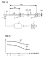
- the second rolling stand 21 is immediately downstream of the first rolling stand 2.
- the second run-in thickness di2 is identical to the first run-out thickness do1. Otherwise, the second inlet thickness di2 is smaller than the first outlet thickness do1.
- a prognosis horizon PH2 for the second rolling stand 21 - hereinafter called the second prognosis horizon PH2 - can be determined independently of the first prognosis horizon PH1.
- the second prognosis horizon PH2 is preferably dimensioned such that during the second prognosis horizon PH2 several band sections 6 are rolled both in the first and in the second rolling stand 2, 21.
- the second forecast horizon PH2 according to FIG. 16 be greater by that period of time, which requires a band section 6 to get from the first stand 2 to the second rolling mill 21.
- the first and the second prognosis horizon PH1, PH2 start in this case at the same location x in front of the first rolling stand 2.
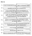
- FIG. 18 are - analogous to FIG. 2 -
- the steps S1 to S4 available.
- the steps S1 to S4 can according to the embodiments of FIGS. 3 to 17 complemented and designed.
- steps S31 to S35 are provided.
- one of the models used for determining the at least one control parameter P can be parameterized by means of a model parameter k.
- the band model 8 can be parameterized by means of the model parameter k.
- the rolling force model 16, the roll stand model 13, etc. could be parameterized by means of the model parameter k.
- step S31 according to FIG. 18 in real-time functional dependencies of the parameters determined directly or indirectly using the parameterizable model 8 of the model parameter k is determined.
- the quantities mentioned in this context are those variables which are needed directly or indirectly using the parameterizable model 8 for determining the at least one control parameter P.
- step S31 for example, functional dependencies of the required rolling forces F, the resulting thermal crowning of the work rolls 9, the material modules M, etc. can be determined.
- the step S31 since it is in addition to the steps S2 and S3, is executed in addition to the determination of the respective quantities themselves.
- step S32 using the parameters determined by means of the parameterizable model 8 - that is to say those variables which are calculated using the parameterizable model 8 in the context of the parameterization model 8 FIGS. 2 to 17 be determined anyway - for the band sections 6 in real time an expected value EW for a measured value MW determined. Furthermore, in step S32, a functional dependence of the expected value EW on the model parameter k is determined.
- the expected value EW can be, for example, the rolling force F with which the corresponding strip section 6 is expected to be rolled, a temperature or a tensile distribution in strip 1.
- the corresponding measured value MW is detected in real time by means of a corresponding measuring device 22 for the respective band section 6.
- the measuring device 22 can be arranged behind the first rolling stand 2, for example for a thickness, tensile or temperature detection (possibly spatially resolved in the bandwidth direction).
- the measuring device 22 may be arranged in front of the first rolling stand 2, for example for a temperature or tension detection (possibly spatially resolved in the bandwidth direction).
- the measuring device 22 - for example for a rolling force or attitude detection - be arranged on the first stand 2 itself.
- step S34 the model parameter k is redetermined based on the measured value MW, the associated expected value EW and the functional dependence of the expected value EW on the model parameter k, ie the corresponding model 8 is newly parameterized, ie the corresponding model 8 is adapted.
- the new, updated model parameter k is used for calculations made by means of the parameterizable model 8 after adapting the parameterizable model 8.
- step S35 the control computer 3 performs the corresponding quantities in real time for the band sections 6 whose temperatures T have already been determined and whose expected temperatures T 'and the corresponding control parameters P have already been predicted.
- the tracking is possible because the functional dependencies of the model parameter k are known.
- the present invention has many advantages. In particular, it is easy to implement, works reliably and delivers superior results.
Description
Die vorliegende Erfindung betrifft ein Steuerverfahren für eine Walzstraße, wobei eine auf ein erstes Walzgerüst der Walzstraße wirkende Stelleinrichtung während des Walzens von Bandabschnitten unter Berücksichtigung mindestens eines Steuerparameters gesteuert wird.The present invention relates to a control method for a rolling line, wherein an actuator acting on a first stand of the rolling line is controlled during the rolling of strip sections taking into account at least one control parameter.
Die vorliegende Erfindung betrifft weiterhin ein Computerprogramm, das Maschinencode umfasst, der von einem Steuerrechner für eine Walzstraße unmittelbar abarbeitbar ist und dessen Abarbeitung durch den Steuerrechner bewirkt, dass der Steuerrechner ein derartiges Steuerverfahren ausführt.The present invention further relates to a computer program comprising machine code which can be processed directly by a control computer for a rolling train and whose execution by the control computer causes the control computer to execute such a control method.
Die vorliegende Erfindung betrifft weiterhin einen Steuerrechner für eine Walzstraße, der derart programmiert ist, dass er im Betrieb ein derartiges Steuerverfahren ausführt.The present invention further relates to a rolling table control computer programmed to execute such a control method in operation.
Die vorliegende Erfindung betrifft weiterhin eine Walzstraße zum Walzen eines Bandes, die zumindest ein erstes Walzgerüst umfasst und mit einem derartigen Steuerrechner ausgestattet ist.The present invention further relates to a rolling train for rolling a belt, which comprises at least a first rolling mill and is equipped with such a control computer.
Temperaturschwankungen über die Breite und die Länge des Bandes können zu erheblichen Störungen im Walzbetrieb führen. Durch die sich ändernde Materialhärte kommt es zu Variationen in der Walzkraft, die wiederum zu anderen Gerüstreaktionen führen kann, die ihrerseits eine Veränderung des Walzspaltprofils zur Folge haben. Beispiele derartiger Gerüstreaktionen sind die Walzenabplattung, die Walzendurchbiegung und die Gerüstauffederung. Hinzu kommt eine Änderung der Walzenbombierung durch den Kontakt der Arbeitswalzen mit dem unterschiedlich warmen Band. Auch dies hat Einfluss auf die Geometrie des Walzspaltes. Werden derartige Veränderungen des Walzspaltprofils nicht berücksichtigt, sind Dicken-, Profil-und Planheitsfehler die Folge.Temperature variations across the width and length of the belt can lead to significant disturbances in the rolling operation. Due to the changing material hardness, there are variations in the rolling force, which in turn can lead to other skeletal reactions, which in turn have a change in the nip profile result. Examples of such framework reactions are roll flattening, roll deflection, and scaffold feathering. In addition, there is a change in the Walzenbombierung by the contact of the work rolls with the different warm band. This also has an influence on the geometry of the roll gap. If such changes in the roll gap profile are not taken into account, thickness, profile and flatness errors are the result.
Die bekannte Sollwertberechnung von Walzstraßen (Stichplanberechnung) kann Temperaturveränderungen in Längsrichtung nur eingeschränkt (Kopf-, Band- und Fußtemperatur) und in Richtung der Bandbreite gar nicht erfassen. Bisher werden derartige Effekte zum Teil mittels automatischer Walzspaltregelungen (AGC = automatic gauge control) kompensiert, welche die Abweichungen der Anstellung durch die Gerüstreaktion zumindest teilweise ausregelt. Weiterhin sind Techniken bekannt, in denen eine Walzkraftmessung im ersten Walzgerüst einer mehrgerüstigen Walzstraße verwendet wird, um die restlichen Walzgerüste vorzusteuern.The well-known setpoint calculation of rolling mills (stitch plan calculation) can detect temperature changes in the longitudinal direction only limited (head, band and foot temperature) and in the direction of the bandwidth. So far, such effects are partly compensated by means of automatic roll gap control (AGC = automatic gauge control), which at least partially corrects the deviations of the employment by the framework reaction. Furthermore, techniques are known in which a rolling force measurement in the first rolling stand of a multi-stand rolling train is used to precede the remaining rolling stands.
Beide Vorgehensweisen sind mit Nachteilen behaftet. So kann die Walzspaltregelung (AGC) nicht auf Schwankungen im Temperaturprofil über die Bandbreite reagieren. Vor allem eine Asymmetrie in der Materialfestigkeit (beispielsweise verursacht durch einen Temperaturkeil) und damit verbunden eine Asymmetrie in der Gerüstreaktion wird nicht berücksichtigt. Weiterhin ist eine Variation der Walzenbombierung nicht oder nur mit Verzögerung erfassbar. Die Vorsteuerung der Walzgerüste einer mehrgerüstigen Walzstraße mittels der Walzkraftmessung im ersten Walzgerüst der Walzstraße ist bei einer eingerüstigen Straße prinzipbedingt nicht anwendbar.Both approaches have disadvantages. Thus, the AGC can not respond to variations in the temperature profile across the bandwidth. In particular, an asymmetry in the material strength (for example, caused by a temperature wedge) and associated asymmetry in the framework reaction is not taken into account. Furthermore, a variation of the Walzenbombierung is not detectable or only with delay. The precontrol of the rolling stands of a multi-stand rolling train by means of the rolling force measurement in the first rolling stand of the rolling train is inherently not applicable to a single-storey street.
Ein weiterer Nachteil beider bekannter Techniken besteht darin, dass sie die gezielte Walzenkühlung zur Anpassung der Walzenbombierung nicht nutzen können. Die gezielte Anpassung der Walzenbombierung ist insbesondere dann hilfreich, wenn die anderen Stellglieder zur Beeinflussung der Walzspaltform (beispielsweise die Walzenrückbiegung und die Walzenverschiebung) an ihre Stellgrenzen gelangen, beispielsweise bei einem Walzkraftanstieg durch einen lokalen Temperatureinbruch.Another disadvantage of both known techniques is that they can not use the targeted roll cooling to adjust the Walzenbombierung. The targeted adjustment of the roll embossing is particularly helpful when the other actuators to affect the roll nip shape (for example, the roll back bending and roll displacement) reach their limits, for example, a rolling force increase by a local temperature dip.
In besonderem Ausmaß tritt dieses Problem bei kombinierten Gießwalzanlagen zutage, bei denen keine oder nur begrenzte Ausgleichsmöglichkeiten für Temperaturschwankungen im Band bestehen, so dass Temperaturprofile (über die Länge und/oder die Bandbreite) sich bis zum Erreichen des Walzgerüsts bzw. der Walzgerüste nicht ausgeglichen haben. Auch bei Warmbreitbandstraße kann es zu Variationen in der Temperatur kommen, beispielsweise durch die so genannten Skidmarks oder eine ungleichmäßige Durchwärmung der Bramme im Ofen.To a particular extent, this problem occurs in combined casting and rolling mills, where there are no or limited compensation for variations in temperature in the belt, so that temperature profiles (over the length and / or the bandwidth) until reaching the roll stand or the rolling stands have not compensated. Even with hot strip mill, it can lead to variations in temperature, for example, by the so-called skidmarks or uneven heating of the slab in the oven.
Aus der
- wobei für Bandabschnitte eines Bandes vor dem ersten Walzgerüst jeweils eine Temperatur ermittelt wird, welche die Bandabschnitte aufweisen,
- wobei mittels eines Bandmodells die Temperaturen der Bandabschnitte für den Zeitpunkt des Walzens des jeweiligen Bandabschnitts in dem ersten Walzgerüst in Echtzeit mitgerechnet werden.
- wherein in each case a temperature is determined for strip sections of a strip in front of the first roll stand, which comprise the strip sections,
- wherein by means of a belt model, the temperatures of the belt sections for the time of rolling of the respective band section in the first rolling stand are counted in real time.
Bei der
Aus der
- wobei für Bandabschnitte eines Bandes vor einem ersten Walzgerüst der Walzstraße jeweils eine Temperatur ermittelt wird, welche die Bandabschnitte aufweisen,
- wobei mittels eines Bandmodells anhand der ermittelten Termperaturen die Temperaturen der Bandabschnitte für den Zeitpunkt des Walzens des jeweiligen Bandabschnitts in dem ersten Walzgerüst prognostiziert werden,
- wobei unter Verwendung der prognostizierten Temperaturen der Bandabschnitte mindestens ein jeweiliger Steuerparameter für das Walzen der Bandabschnitte in dem ersten Walzgerüst ermittelt wird,
- wobei eine auf das erste Walzgerüst wirkende Stelleinrichtung während des Walzens des jeweiligen Bandabschnitts unter Berücksichtigung des jeweiligen ermittelten Steuerparameters gesteuert wird.
- wherein in each case a temperature is determined for strip sections of a strip in front of a first roll stand of the rolling train, which strip sections have,
- wherein by means of a belt model on the basis of the determined temperatures the temperatures of the belt sections are predicted for the time of rolling of the respective belt section in the first rolling mill,
- wherein, using the predicted temperatures of the belt sections, at least one respective control parameter for rolling the belt sections in the first rolling mill is determined,
- wherein an acting on the first rolling stand actuator during the rolling of the respective band section under Considering the respective determined control parameter is controlled.
Aus der
Die Aufgabe der vorliegenden Erfindung besteht darin, Möglichkeiten zu schaffen, mittels derer der Temperaturverlauf des Bandes beim Walzen des Bandes auf besonders vorteilhafte Weise berücksichtigt werden kann. Insbesondere soll der Temperaturverlauf des Bandes bei der Profileinstellung des Walzspalts berücksichtigt werden können.The object of the present invention is to provide ways by which the temperature profile of the belt during rolling of the belt can be taken into account in a particularly advantageous manner. In particular, the temperature profile of the strip should be taken into account in the profile adjustment of the roll gap.
Die Aufgabe wird durch ein Steuerverfahren mit den Merkmalen des Anspruchs 1 gelöst. Vorteilhafte Ausgestaltungen des erfindungsgemäßen Steuerverfahrens sind Gegenstand der abhängigen Ansprüche 2 bis 11.The object is achieved by a control method having the features of
Erfindungsgemäß ist bei einem Steuerverfahren für eine Walzstraße vorgesehen,
- dass die Temperaturen der Bandabschnitte für den Zeitpunkt des Walzens des jeweiligen Bandabschnitts in dem ersten Walzgerüst mittels des Bandmodells mit einem ersten Prognosehorizont prognostiziert werden,
- dass der erste Prognosehorizont mit mehreren in dem ersten Walzgerüst zu walzenden Bandabschnitten korrespondiert,
- dass für den ersten Prognosehorizont ein Stellgrößenverlauf für die Stelleinrichtung angesetzt wird,
- dass mittels des Stellgrößenverlaufs ein Profil eines von Arbeitswalzen des ersten Walzgerüsts gebildeten Walzspalts beeinflusst wird,
- dass mittels eines Walzgerüstmodells für das erste Walzgerüst unter Verwendung der prognostizierten Temperaturen der Bandabschnitte und des angesetzten Stellgrößenverlaufs für die mit dem ersten Prognosehorizont korrespondierenden Bandabschnitte ein jeweiliges Walzspaltprofil prognostiziert wird, das die Arbeitswalzen des ersten Walzgerüsts zum Zeitpunkt des Walzens des jeweiligen Bandabschnitts bilden,
- dass der angesetzte Stellgrößenverlauf anhand des für die Bandabschnitte prognostizierten Walzspaltprofils und eines jeweiligen Sollprofils optimiert wird und
- dass der aktuelle Wert des optimierten Stellgrößenverlaufs dem Steuerparameter entspricht und der Stelleinrichtung als Stellgröße vorgegeben wird.
- the temperatures of the strip sections for the time of rolling of the respective strip section in the first roll stand are predicted by means of the strip model with a first forecast horizon,
- that the first prognosis horizon corresponds to a plurality of band sections to be rolled in the first rolling stand,
- that for the first forecast horizon a manipulated variable profile for the actuating device is set,
- in that a profile of a roll gap formed by work rolls of the first roll stand is influenced by means of the manipulated variable profile,
- in that, by means of a rolling stand model for the first roll stand, using the predicted temperatures of the strip sections and the applied control curve for the belt sections corresponding to the first forecast horizon, a respective roll gap profile is formed which forms the work rolls of the first rolling mill at the time of rolling of the respective strip section;
- the set manipulated variable profile is optimized on the basis of the rolling gap profile predicted for the strip sections and a respective desired profile, and
- that the current value of the optimized manipulated variable course corresponds to the control parameter and the setting device is specified as manipulated variable.
Die letztgenannte Vorgehensweise kann dadurch noch weiter verbessert werden,
- dass einem Walzkraftmodell zumindest die prognostizierten Temperaturen zugeführt werden,
- dass mittels des Walzkraftmodells unter Verwendung der prognostizierten Temperaturen für die mit dem ersten Prognosehorizont korrespondierenden Bandabschnitte die zum Walzen des jeweiligen Bandabschnitts in dem ersten Walzgerüst jeweils erforderliche Walzkraft prognostiziert wird und
- dass die Walzspaltprofile mittels des Walzgerüstmodells unter Verwendung der prognostizierten Walzkräfte prognostiziert werden.
- that a rolling force model at least the forecast temperatures are supplied,
- that by means of the rolling force model, using the predicted temperatures for the band sections corresponding to the first prognosis horizon, the respective rolling force required for rolling the respective band section in the first rolling stand is predicted, and
- that the nip profiles are predicted by means of the rolling stand model using the predicted rolling forces.
Die Stelleinrichtung für die Beeinflussung des Walzspaltprofils kann nach Bedarf ausgebildet sein. Insbesondere kommen eine Walzenrückbiegung und/oder eine Walzenverschiebung in Frage. Vorzugsweise umfasst die Stelleinrichtung eine Walzenkühleinrichtung. Die Walzenkühleinrichtung kann insbesondere in Bandbreitenrichtung ortsaufgelöst ansteuerbar sein.The adjusting device for influencing the roll gap profile can be designed as required. In particular, a roll back bending and / or a roll displacement come into question. Preferably, the adjusting device comprises a roll cooling device. The roll cooling device can be controlled in a spatially resolved manner, in particular in the bandwidth direction.
Es ist möglich, dass das Steuerverfahren mit einem zweiten Prognosehorizont auch für ein zweites, dem ersten Walzgerüst nachgeordnetes Walzgerüst der Walzstraße ausgeführt wird. In diesem Fall werden die Bandabschnitte in dem ersten Walzgerüst von einer ersten Einlaufdicke auf eine erste Auslaufdicke und in dem zweiten Walzgerüst von einer zweiten Einlaufdicke auf eine zweite Auslaufdicke gewalzt.It is possible that the control method with a second prognosis horizon is also carried out for a second rolling stand of the rolling train downstream of the first rolling stand. In In this case, the strip sections in the first rolling stand are rolled from a first inlet thickness to a first outlet thickness and in the second rolling stand from a second inlet thickness to a second outlet thickness.
Es ist möglich, dass die erste Auslaufdicke und/oder die zweite Einlaufdicke bandabschnittspezifisch bestimmt sind. Durch diese Vorgehensweise kann insbesondere im laufenden Walzbetrieb eine Lastumverteilung zwischen dem ersten und dem zweiten Walzgerüst erfolgen.It is possible that the first outlet thickness and / or the second inlet thickness are determined band-specific. As a result of this procedure, load redistribution between the first and the second roll stand can take place, in particular during ongoing rolling operation.
Der Prognosehorizont für das zweite Walzgerüst kann nach Bedarf bestimmt sein, er muss jedoch - analog zum Prognosehorizont für das erste Walzgerüst - derart bemessen sein, dass er mit mehreren Bandabschnitten korrespondiert, dass also während des Prognosehorizonts für das zweite Walzgerüst in dem zweiten Walzgerüst mehrere Bandabschnitte gewalzt werden. Vorzugsweise ist der zweite Prognosehorizont derart bemessen, dass während des zweiten Prognosehorizonts mehrere Bandabschnitte sowohl in dem ersten als auch in dem zweiten Walzgerüst gewalzt werden. Insbesondere können die Prognosehorizonte für das erste und das zweite Walzgerüst derart bemessen werden, dass die Differenz der Prognosehorizonte der Zeit entspricht, die ein Bandabschnitt benötigt, um vom ersten Walzgerüst zum zweiten Walzgerüst zu gelangen. Die Prognosehorizonte können sozusagen an der gleichen, vor dem ersten Walzgerüst angeordneten Stelle aufsetzen.The prognosis horizon for the second roll stand can be determined as required, but it must be dimensioned - analogous to the forecast horizon for the first roll stand - such that it corresponds to several strip sections, ie during the forecast horizon for the second rolling mill stand in the second rolling stand to be rolled. Preferably, the second prognosis horizon is dimensioned such that during the second prognosis horizon several strip sections are rolled both in the first and in the second rolling stand. In particular, the forecast horizons for the first and the second roll stand can be dimensioned such that the difference of the forecast horizon corresponds to the time it takes for a strip section to pass from the first roll stand to the second roll stand. The forecast horizons can be placed, so to speak, at the same location in front of the first mill stand.
In manchen Fällen kann die Verformbarkeit des Bandes - beispielsweise aufgrund von Temperatur- und/oder Verfestigungsunterschieden - auch über die Breite des Bandes variieren. In einem derartigen Fall ist vorzugsweise vorgesehen,
- dass für die Bandabschnitte unter Verwendung der prognostizierten Temperaturen für den Zeitpunkt des Walzens des jeweiligen Bandabschnitts in dem ersten Walzgerüst ein jeweiliger aktueller bedienseitiger und ein jeweiliger aktueller antriebsseitiger Materialmodul prognostiziert werden,
- dass mittels der Stelleinrichtung bedienseitig und antriebsseitig ein Walzspalt des ersten Walzgerüsts beeinflussbar ist und
- dass die Materialmodule den Steuerparametern entsprechen und zum Zeitpunkt des Walzens des jeweiligen Bandabschnitts in dem ersten Walzgerüst für die Parametrierung einer bedienseitigen und einer antriebsseitigen Walzspaltsteuerung herangezogen werden.
- that for the strip sections using the predicted temperatures for the time of rolling of the respective strip section in the first rolling stand, a respective current operating-side and a respective current drive-side material module are predicted,
- that by means of the adjusting device on the operating side and the drive side, a roll gap of the first rolling stand can be influenced and
- the material modules correspond to the control parameters and, at the time of rolling of the respective strip section in the first rolling stand, are used for the parameterization of an operating-side and a drive-side roll gap control.
Die erfindungsgemäßen Vorgehensweisen können dadurch noch weiter verbessert werden,
- dass das Bandmodell ein Materialmodell umfasst, mittels dessen für die in dem ersten Walzgerüst zu walzenden Bandabschnitte für den Zeitpunkt des Walzens des jeweiligen Bandabschnitts in dem ersten Walzgerüst jeweils eine zu erwartende, von der Temperatur verschiedene Materialeigenschaft prognostiziert wird und
- dass die prognostizierten Materialeigenschaften bei der Ermittlung des mindestens einen Steuerparameters berücksichtigt werden.
- in that the belt model comprises a material model by means of which an expected temperature characteristic different from the temperature is predicted for the strip sections to be rolled in the first rolling stand for the time of rolling of the respective strip section in the first rolling mill, and
- that the predicted material properties are taken into account when determining the at least one control parameter.
In manchen Fällen kann es ausreichen, die Temperaturen für die Bandabschnitte als skalare Größen zu prognostizieren. Oftmals ist es jedoch von Vorteil, wenn die mittels des Bandmodells prognostizierten Temperaturen der Bandabschnitte in Bandbreitenrichtung ortsaufgelöst sind. Vorzugsweise sind in diesem Fall bereits die für die Bandabschnitte ermittelten Temperaturen in Bandbreitenrichtung ortsaufgelöst.In some cases it may be sufficient to forecast the temperatures for the band sections as scalar quantities. Often, however, it is advantageous if the predicted by means of the tape model temperatures of the band sections in the bandwidth direction are spatially resolved. Preferably, in this case, the temperatures determined for the strip sections are already spatially resolved in the bandwidth direction.
Modelle für Anlagen der Grundstoffindustrie sind aufgrund der Komplexität der zu modellierenden Vorgänge in Verbindung mit der nur begrenzt möglichen Datenerfassung üblicherweise fehlerbehaftet. Um derartige Fehler in Echtzeit korrigieren zu können, ist vorzugsweise vorgesehen,
- dass das Bandmodell und/oder ein anderes, im Rahmen der Ermittlung des mindestens einen Steuerparameters verwendetes Modell mittels eines Modellparameters parametrierbar ist,
- dass zusätzlich zu im Rahmen der Ermittlung des mindestens einen Steuerparameters unter Verwendung des parametrierbaren Modells ermittelten Größen in Echtzeit funktionale Abhängigkeiten der ermittelten Größen von dem Modellparameter ermittelt werden,
- dass für die Bandabschnitte in Echtzeit unter Verwendung der mittels des parametrierbaren Modells ermittelten Größen ein Erwartungswert für einen Messwert und eine funktionale Abhängigkeit des Erwartungswertes von dem Modellparameter ermittelt werden,
- dass für die Bandabschnitte mittels einer vor, an oder hinter dem ersten Walzgerüst angeordneten Messeinrichtung in Echtzeit jeweils der entsprechende Messwert erfasst wird,
- dass anhand des Messwerts, des Erwartungswertes und der funktionalen Abhängigkeit des Erwartungswertes von dem Modellparameter der Modellparameter neu bestimmt wird,
- dass das parametrierbare Modell anhand des neu bestimmten Modellparameters neu parametriert wird und
- dass die für die Bandabschnitte im Rahmen der Ermittlung des mindestens einen Steuerparameters unter Verwendung des parametrierbaren Modells bereits ermittelten Größen in Echtzeit nachgeführt werden.
- that the band model and / or another model used in the course of determining the at least one control parameter can be parameterized by means of a model parameter,
- that, in addition to variables determined in the course of determining the at least one control parameter using the parameterizable model, functional dependencies of the determined variables on the model parameter are determined in real time;
- in that an expected value for a measured value and a functional dependency of the expected value on the model parameter are determined for the band sections in real time using the variables determined by means of the parameterizable model,
- that in each case the corresponding measured value is recorded in real time for the band sections by means of a measuring device arranged in front of, at or behind the first rolling stand,
- the model parameter is newly determined on the basis of the measured value, the expected value and the functional dependency of the expected value on the model parameter,
- that the parametrizable model is newly parameterized on the basis of the newly determined model parameter, and
- that the quantities already determined for the band sections during the determination of the at least one control parameter using the parameterizable model are tracked in real time.
Dadurch wird insbesondere erreicht, dass das fehlerbehaftete Modell im laufenden Betrieb, also während des Walzens der Bandabschnitte, adaptiert werden kann.This achieves in particular that the faulty model can be adapted during operation, that is to say during the rolling of the band sections.
Die Aufgabe wird weiterhin durch ein Computerprogramm mit den Merkmalen des Anspruchs 12 gelöst. Erfindungsgemäß bewirkt die Abarbeitung des Maschinencodes durch den Steuerrechner, dass der Steuerrechner ein erfindungsgemäßes Steuerverfahren ausführt.The object is further achieved by a computer program having the features of
Die Aufgabe wird weiterhin durch einen Steuerrechner mit den Merkmalen des Anspruchs 13 gelöst. Erfindungsgemäß ist der Steuerrechner derart programmiert, dass er im Betrieb ein erfindungsgemäßes Steuerverfahren ausführt.The object is further achieved by a control computer having the features of
Die Aufgabe wird weiterhin durch eine Walzstraße mit den Merkmalen des Anspruchs 14 gelöst. Erfindungsgemäß ist eine Walzstraße zum Walzen eines Bandes, die zumindest ein erstes Walzgerüst umfasst, mit einem erfindungsgemäß programmierten Steuerrechner ausgestattet.The object is further achieved by a rolling mill with the features of claim 14. According to the invention, a rolling train for rolling a belt, which comprises at least a first roll stand, is equipped with a control computer programmed according to the invention.
Weitere Vorteile und Einzelheiten ergeben sich aus der nachfolgenden Beschreibung von Ausführungsbeispielen in Verbindung mit den Zeichnungen. Es zeigen in schematischer Prinzipdarstellung:
- FIG 1
- eine Walzstraße,
- FIG 2
und 3 - Ablaufdiagramme,
- FIG 4
- ein erstes Walzgerüst,
- FIG 5
- ein Blockschaltbild,
- FIG 6
- ein Ablaufdiagramm,
- FIG 7
- ein Blockschaltbild,
- FIG 8
- ein Ablaufdiagramm,
- FIG 9
- ein Blockschaltbild,
- FIG 10
- ein Ablaufdiagramm,
- FIG 11
- ein Blockschaltbild,
- FIG 12
- ein Ablaufdiagramm,
- FIG 13
- ein Blockschaltbild,
- FIG 14
und 15 - jeweils einen Bandabschnitt zu verschiedenen Zeitpunkten,
- FIG 16
- eine mehrgerüstige Walzstraße,
- FIG 17
- einen Ein- und einen Auslaufdickenverlauf,
- FIG 18
- ein Ablaufdiagramm und
- FIG 19
- eine mehrgerüstige Walzstraße.
- FIG. 1
- a rolling mill,
- FIGS. 2 and 3
- Flowcharts,
- FIG. 4
- a first rolling stand,
- FIG. 5
- a block diagram,
- FIG. 6
- a flow chart,
- FIG. 7
- a block diagram,
- FIG. 8
- a flow chart,
- FIG. 9
- a block diagram,
- FIG. 10
- a flow chart,
- FIG. 11
- a block diagram,
- FIG. 12
- a flow chart,
- FIG. 13
- a block diagram,
- FIGS. 14 and 15
- one band section at different times,
- FIG. 16
- a multi-stand rolling mill,
- FIG. 17
- an inlet and a outlet thickness profile,
- FIG. 18
- a flow chart and
- FIG. 19
- a multi-stand rolling mill.
Gemäß
Die Walzstraße und damit auch das erste Walzgerüst 2 werden von einem Steuerrechner 3 gesteuert. Der Steuerrechner 3 ist mit einem Computerprogramm 4 programmiert. Das Computerprogramm 4 umfasst Maschinencode 5, der von dem Steuerrechner 3 unmittelbar abarbeitbar ist. Das Abarbeiten des Maschinencodes 5 durch den Steuerrechner 3 - also der Betrieb des Steuerrechners 3 - bewirkt, dass der Steuerrechner 3 mindestens eines - ggf. auch mehrere - der Steuerverfahren ausführt, die nachfolgend in Verbindung mit den
Gemäß
Unabhängig davon, auf welche Weise die Temperaturen T der Bandabschnitte 6 ermittelt werden, erfolgt die Ermittlung des Schrittes S1 jedoch für einen Ort x, der sich vor dem ersten Walzgerüst 2 befindet. Die Temperatur T ist also für die jeweilige Temperatur T des jeweiligen Bandabschnitts 6 zu einem Zeitpunkt charakteristisch, zu dem sich der entsprechende Bandabschnitt 6 noch vor dem ersten Walzgerüst 2 befindet.Regardless of how the temperatures T of the
Der Steuerrechner 3 implementiert aufgrund der Programmierung mit dem Computerprogramm 4 unter anderem ein Bandmodell 8. Das Bandmodell 8 modelliert mittels mathematisch-physikalischer Gleichungen zumindest das Temperaturverhalten des Bandes 1. Insbesondere wird mittels des Bandmodells 8 für die Bandabschnitte 6 eine Wärmeleitungsgleichung gelöst. Im Rahmen des Lösens der Wärmeleitungsgleichung werden insbesondere die interne Wärmeleitung innerhalb des Bandes 1 als auch die Wechselwirkung des Bandes 1 mit seiner Umgebung berücksichtigt, beispielsweise die Wechselwirkung mit Kühl- und Heizeinrichtungen, einem Zunderwäscher, dem Kontakt mit Transportrollen, dem Kontakt mit Arbeitswalzen 9 des ersten Walzgerüsts 2 usw.. Weiterhin kann, falls dies erforderlich ist, gekoppelt mit der Wärmeleitungsgleichung auch eine Phasenumwandlungsgleichung gelöst werden. Die entsprechenden Vorgehensweisen sind Fachleuten allgemein bekannt. Eine vorteilhafte Wärmeleitungsgleichung ist beispielsweise in der
Mittels des Bandmodells 8 prognostiziert der Steuerrechner 3 in einem Schritt S2 somit anhand der ermittelten Temperaturen T die Temperatur der Bandabschnitte 6 für den Zeitpunkt des Walzens des jeweiligen Bandabschnitts 6 in dem ersten Walzgerüst 2. Die prognostizierte Temperatur ist zur Unterscheidung von der ermittelten Temperatur T mit dem Bezugszeichen T' versehen.By means of the
Die Prognose erfolgt mit einem Prognosehorizont PH1, nachfolgend als erster Prognosehorizont PH1 bezeichnet. Der erste Prognosehorizont PH1 entspricht der Anzahl von Zeitschritten, um die das Bandmodell 8 die Temperatur T' prognostiziert, wobei während jedes Zeitschrittes jeweils ein Bandabschnitt 6 im ersten Walzgerüst 2 gewalzt wird.The forecast is made with a forecast horizon PH1, hereinafter referred to as the first forecast horizon PH1. The first forecast horizon PH1 corresponds to the number of time steps by which the
Minimal umfasst der erste Prognosehorizont PH1 einen einzigen Zeitschritt. Ein minimaler Prognosehorizont PHmin ist somit dadurch bestimmt, dass die Prognostizierung der Temperatur der Bandabschnitte 6 um einen einzigen Zeitschritt voreilt. In diesem Fall wird also während des ersten Prognosehorizontes PH1 in dem ersten Walzgerüst 2 ein einziger Bandabschnitt 6 gewalzt, nämlich der unmittelbar vorhergehende Bandabschnitt 6. In manchen Ausgestaltungen der vorliegenden Erfindung - dies wird später näher erläutert werden - ist der erste Prognosehorizont PH1 jedoch derart bemessen, dass während des ersten Prognosehorizonts PH1 in dem ersten Walzgerüst 2 mehrere Bandabschnitte 6 gewalzt werden, beispielsweise fünf, acht, zehn oder noch mehr Bandabschnitte 6.At a minimum, the first forecast horizon PH1 comprises a single time step. A minimal forecast horizon PHmin is thus determined by the fact that the prediction of the temperature of the
In einem Schritt S3 ermittelt der Steuerrechner 3 unter Verwendung der prognostizierten Temperaturen T' der Bandabschnitte 6 jeweils mindestens einen Steuerparameter P für das Walzen des jeweiligen Bandabschnitts 6 in dem ersten Walzgerüst 2. In einem Schritt S4 steuert der Steuerrechner 3 eine Stelleinrichtung 10. Die Stelleinrichtung 10 wirkt auf das erste Walzgerüst 2. Die Steuerung der Stelleinrichtung 10 erfolgt während des Walzens des jeweiligen Bandabschnitts 6 unter Berücksichtigung des für den momentan zu walzenden Bandabschnitt 6 ermittelten Steuerparameters P.In a step S3, the
Die Vorgehensweise von
Man nehme an, zu einem bestimmten Zeitpunkt wird für einen bestimmten Bandabschnitt 6 eine bestimmte Temperatur T ermittelt, beispielsweise messtechnisch erfasst (Schritt S1). Der entsprechende Bandabschnitt 6 wird während seines Transports durch die Walzstraße wegverfolgt. Die Temperatur T', die für den entsprechenden Bandabschnitt 6 erwartet wird, wird kontinuierlich mitgerechnet (Schritt S2), wobei die modellgestützte Temperaturprognose dem Ort des entsprechenden Bandabschnitts 6 mindestens einen Zeitschritt voraus ist. Zu dem Zeitpunkt, zu dem sich der betrachtete Bandabschnitt 6 unmittelbar vor dem ersten Walzgerüst 2 befindet - im ersten Walzgerüst 2 also der unmittelbar vorhergehende Bandabschnitt 6 gewalzt wird -, wird der Steuerparameter P für den betrachteten Bandabschnitt 6 ermittelt. Der Steuerparameter P ist dem Steuerrechner 3 daher rechtzeitig bekannt, so dass der Steuerrechner 3 den Steuerparameter P bei der Steuerung der Stelleinrichtung 10 berücksichtigen kann, wenn der betrachtete Bandabschnitt 6 im ersten Walzgerüst 2 gewalzt wird. In die Ermittlung des Steuerparameters P gehen alternativ die prognostizierte Temperatur T' des unmittelbar vor dem ersten Walzgerüst 2 befindlichen Bandabschnitts 6 oder - falls der erste Prognosehorizont PH1 größer als der minimale Prognosehorizont PHmin ist - zusätzlich die prognostizierten Temperaturen T' weiterer Bandabschnitte 6 ein.It is assumed that at a certain point in time a specific temperature T is determined for a
Die Vorgehensweise von
Für manche Ausgestaltungen der vorliegenden Erfindung benötigt der Steuerrechner 3 auch die prognostizierten Temperaturen T' und evtl. auch sonstige Eigenschaften anderer Bandabschnitte 6 und/oder prognostizierte Eigenschaften des ersten Walzgerüsts 2. Soweit es sich um nach dem betrachteten Bandabschnitt 6 zu walzende Bandabschnitte 6 handelt, sind deren Temperaturen und Eigenschaften dem Steuerrechner 3 bekannt, wenn sie innerhalb des ersten Prognosehorizonts PH1 liegen. Beispielsweise sind dem Steuerrechner 3 bei einem ersten Prognosehorizont PH1 von acht Bandabschnitten 6 zu dem Zeitpunkt, zu dem für einen bestimmten Bandabschnitt 6 dessen Temperatur T ermittelt wird, aufgrund der bereits zuvor durchgeführten Prognose die erwarteten Temperaturen T' der sieben nachfolgenden Bandabschnitte 6 bereits bekannt. Anders ausgedrückt: Bei einem ersten Prognosehorizont PH1 von acht Bandabschnitten 6 sind zu jedem Zeitpunkt die prognostizierten Temperaturen T' der acht vor dem ersten Walzgerüst 2 befindlichen Bandabschnitte 6 bekannt. Sie können daher für die Ermittlung des Steuerparameters P für den Bandabschnitt 6, der im ersten Walzgerüst 2 als nächstes gewalzt wird, berücksichtigt werden. Soweit es sich um vor dem betrachteten Bandabschnitt 6 zu walzende Bandabschnitte 6 handelt, sind deren Temperaturen und Eigenschaften dem Steuerrechner 3 aus der Vergangenheit bekannt.For some embodiments of the present invention, the
In Verbindung mit
Gemäß
Der Schritt S3 von
Im Schritt S6 wird gemäß
Einem Stellgrößenoptimierer 12 - siehe
- die prognostizierten Temperaturen T', welche die im ersten Prognosehorizont PH1 liegenden Bandabschnitte 6 zum Zeitpunkt des Walzens des jeweiligen Bandabschnitts 6
im ersten Walzgerüst 2 aufweisen und - der Stellgrößenverlauf S(t) für den ersten Prognosehorizont PH1.
- the predicted temperatures T ', which have the
band portions 6 lying in the first forecasting horizon PH1 at the time of rolling of therespective band section 6 in thefirst rolling stand 2, and - the manipulated variable course S (t) for the first prognosis horizon PH1.
Der Stellgrößenoptimierer 12 ist ein von dem Steuerrechner 3 implementierter Softwareblock. Er umfasst unter anderem ein Walzgerüstmodell 13. Das Walzgerüstmodell 13 modelliert insbesondere die thermische Balligkeit der Arbeitswalzen 9 und den Verschleiß der Arbeitswalzen 9, der sich durch den Kontakt der Arbeitswalzen 9 mit dem Band 1 ergibt. Das Walzgerüstmodell 13 modelliert weiterhin den Einfluss des Stellgrößenverlaufs S(t) auf den Walzspalt, beispielsweise den Einfluss der Walzenkühleinrichtung 11 auf die thermische Balligkeit.The manipulated
Das Walzgerüstmodell 13 prognostiziert im Schritt S8 als Ausgangsgröße einen zeitlichen Walzspaltprofilverlauf W(t). Das Walzgerüstmodell 13 ermittelt also im Schritt S8 für jeden innerhalb des ersten Prognosehorizontes PH1 liegenden Bandabschnitt 6 das Walzspaltprofil W, dass sich für den jeweiligen Bandabschnitt 6 ergibt. Das Walzgerüstmodell 13 ermittelt den Walzspaltprofilverlauf W(t) unter Verwendung des ihm zugeführten Stellgrößenverlaufs S(t) und der prognostizierten Temperaturen T' der Bandabschnitte 6.The rolling
Der Walzspaltprofilverlauf W(t) wird gemäß den
Zum Optimieren des Stellgrößenverlaufs S(t) wird der ermittelte Walzspaltprofilverlauf W(t) mit einem Sollprofilverlauf W* (t) verglichen. Der Sollprofilverlauf W* (t) kann konstant sein. Unabhängig davon, ob der Sollprofilverlauf W* (t) konstant ist oder nicht, ist das vorrangige Ziel der Optimierung, die Planheit des Bandes 1 zu gewährleisten. Nachrangig sollte nach Möglichkeit ein möglichst gleichmäßiges Profil gewalzt werden.In order to optimize the manipulated variable profile S (t), the determined roll gap profile profile W (t) is compared with a desired profile profile W * (t). The desired profile profile W * (t) can be constant. Regardless of whether the desired profile profile W * (t) is constant or not, the primary aim of the optimization is to ensure the flatness of the
Vorzugsweise ist die Temperaturerfassung gemäß
Der optimierte Stellgrößenverlauf S(t) wird gemäß
Es ist möglich, dass der Stellgrößenoptimierer 12 den im Rahmen von
Die obenstehend in Verbindung mit den
Gemäß
Gemäß
Die Vorgehensweise der
Gemäß
Gegebenenfalls kann eine uni- oder bidirektionale Kopplung zwischen der Temperaturentwicklung und der Entwicklung der weiteren Materialeigenschaft bestehen. Im erstgenannten Fall wird zunächst mittels des Temperaturmodells 17 der Verlauf der Temperatur des betrachteten Bandabschnitts 6 während des ersten Prognosehorizonts PH1 bestimmt, sodann der ermittelte zeitliche Temperaturverlauf dem Materialmodell 18 vorgegeben und schließlich anhand des Materialmodells 18 die weitere Materialeigenschaft ermittelt. Im letztgenannten Fall erfolgt ein schrittweise gekoppeltes Ermitteln der prognostizierten Temperatur T' und der prognostizierten weiteren Materialeigenschaft des jeweils betrachteten Bandabschnitts 6.Optionally, a unidirectional or bidirectional coupling between the temperature development and the development of the further material property can exist. In the former case, the course of the temperature of the considered
Im Schritt S17 werden dem Walzkraftmodell 16 - zusätzlich zu den im Schritt S11 genannten Werten und Größen - auch die entsprechenden weiteren Materialeigenschaften für die entsprechenden Bandabschnitte 6 zugeführt. Im Schritt S18 prognostiziert das Walzkraftmodell 16 die erforderlichen Walzkräfte F unter zusätzlicher Berücksichtigung auch der weiteren Materialeigenschaften.In step S17, the rolling force model 16 - in addition to the values and sizes mentioned in step S11 - are also supplied with the corresponding further material properties for the
Da die weiteren Materialeigenschaften Einfluss auf die prognostizierten Walzkräfte F, diese wiederum auf das Walzspaltprofil W und dieses wiederum auf den optimierten Stellgrößenverlauf S(t) hat, berücksichtigt der Steuerrechner 3 im Ergebnis bei der Vorgehensweise der
Obenstehend wurde als Beispiel für die Ermittlung eines Steuerparameters P die Ermittlung einer Stellgröße S erläutert, mittels derer das Profil des von den Arbeitswalzen 9 gebildeten Walzspalts beeinflusst wird. Nachfolgend wird in Verbindung mit den
Im Schritt S21 wird - analog zum Schritt S2 - die Temperatur T' des entsprechenden Bandabschnitts 6 prognostiziert. Im Unterschied zum Schritt S2 von
Der erste Prognosehorizont PH1 kann bei der Ausgestaltung von
Im Schritt S22 wird in Ermittlungsblöcken 19 - getrennt für die Bedien- und die Antriebsseite - unter Verwendung der für die jeweilige Seite des ersten Walzgerüsts 2 für den jeweiligen Bandabschnitt 6 prognostizierten Temperaturen T' ein jeweiliger aktueller Materialmodul M prognostiziert, der für den Zeitpunkt erwartet wird, zu dem der entsprechende Bandabschnitt 6 im ersten Walzgerüst 2 gewalzt wird. Der jeweilige Materialmodul M ist im Wesentlichen für die Festigkeit bzw. Verformbarkeit des entsprechenden Bandabschnitts 6 auf der entsprechenden Seite des ersten Walzgerüsts 2 charakteristisch.In step S22, a respective current material module M, which is expected for the time, is predicted in determination blocks 19-separately for the operator side and the drive side-using the temperatures T 'predicted for the respective side of the
Mittels der Stelleinrichtung 10 ist - und zwar zumindest in Grenzen unabhängig voneinander - jeweils ein Stellglied 20 (beispielsweise eine Hydraulikzylindereinheit) ansteuerbar, mittels derer die Walzkraft F antriebs- und bedienseitig auf die Arbeitswalzen 9 aufbringbar ist und so der Walzspalt beeinflussbar ist. Gemäß den
Analog zur Ergänzung der
Mittels des Temperaturmodells 17 wird im Schritt S26 - analog zum Schritt S21 von
Gemäß
Im Rahmen der Vorgehensweise der
Für die Vorgehensweise der
Gegebenenfalls kann es auch in diesem Fall ausreichend sein, die erstmalige Ermittlung der Temperatur T - also am Anfang des ersten Prognosehorizontes PH1 - in Bandbreitenrichtung nicht ortsaufgelöst vorzunehmen. Dies kann beispielsweise möglich sein, wenn das Band 1 zwar anfänglich eine einheitliche Temperatur T aufweist, aber in Bandbreitenrichtung einen Dickenkeil aufweist und daher auf der dünnen Seite schneller abkühlt als auf der dickeren Seite. In der Regel wird jedoch auch die erstmalige Ermittlung der Temperatur T der Bandabschnitte 6 in diesem Fall entsprechend der gestrichelten Darstellung in den
In manchen Fällen ist es ausreichend, wenn die Walzstraße ein einziges Walzgerüst aufweist, also nur das erste Walzgerüst 2 vorhanden ist. Ein einziges Walzgerüst kann insbesondere dann ausreichend sein, wenn ein sehr endabmessungsnahes Gießen des Bandes 1 erfolgt, beispielsweise mittels rotierender Gießwalzen. In vielen Fällen sind jedoch mehrere Walzgerüste vorhanden. Beispielsweise weist eine mehrgerüstige Fertigstraße in der Regel sechs oder sieben Walzgerüste auf.In some cases, it is sufficient if the rolling train has a single rolling mill, that is, only the
In dem Fall, dass mehrere Walzgerüste vorhanden sind, ist es möglich, das erfindungsgemäße Steuerverfahren gemäß
Gemäß der Darstellung von
Es ist möglich, dass entsprechend der im Stand der Technik üblichen Vorgehensweise für die - gemäß
Es ist möglich, das erfindungsgemäße Steuerverfahren für das zweite Walzgerüst 21 unabhängig von dem Steuerverfahren für das erste Walzgerüst 2 auszuführen. In diesem Fall kann ein Prognosehorizont PH2 für das zweite Walzgerüst 21 - nachfolgend zweiter Prognosehorizont PH2 genannt - unabhängig vom ersten Prognosehorizont PH1 bestimmt werden. Vorzugsweise ist der zweite Prognosehorizont PH2 jedoch derart bemessen, dass während des zweiten Prognosehorizonts PH2 mehrere Bandabschnitte 6 sowohl im ersten als auch im zweiten Walzgerüst 2, 21 gewalzt werden. Insbesondere kann der zweite Prognosehorizont PH2 gemäß
Das bisher erläuterte Steuerverfahren liefert bereits sehr gute Ergebnisse, kann jedoch noch weiter verbessert werden. Dies wird nachfolgend in Verbindung mit den
Gemäß
Im Rahmen von
Im Schritt S31 werden gemäß
Im Schritt S32 wird unter Verwendung der mittels des parametrierbaren Modells 8 ermittelten Größen - also derjenigen Größen, die unter Verwendung des parametrierbaren Modells 8 im Rahmen der
Im Schritt S33 wird in Echtzeit mittels einer entsprechenden Messeinrichtung 22 für den jeweiligen Bandabschnitt 6 der entsprechende Messwert MW erfasst. Die Messeinrichtung 22 kann - beispielsweise für eine (ggf. in Bandbreitenrichtung ortsaufgelöste) Dicken-, Zug- oder Temperaturerfassung - hinter dem ersten Walzgerüst 2 angeordnet sein. Alternativ kann die Messeinrichtung 22 - beispielsweise für eine (ggf. in Bandbreitenrichtung ortsaufgelöste) Temperatur- oder Zugerfassung - vor dem ersten Walzgerüst 2 angeordnet sein. Wiederum alternativ kann die Messeinrichtung 22 - beispielsweise für eine Walzkraft- oder Anstellungserfassung - am ersten Walzgerüst 2 selbst angeordnet sein.In step S33, the corresponding measured value MW is detected in real time by means of a
Im Schritt S34 wird anhand des Messwerts MW, des zugehörigen Erwartungswerts EW und der funktionalen Abhängigkeit des Erwartungswerts EW von dem Modellparameter k der Modellparameter k neu bestimmt, das entsprechende Modell 8 also neu parametriert, das entsprechende Modell 8 also adaptiert. Für Berechnungen, die mittels des parametrierbaren Modells 8 nach dem Adaptieren des parametrierbaren Modells 8 vorgenommen werden, wird der neue, aktualisierte Modellparameter k verwendet.In step S34, the model parameter k is redetermined based on the measured value MW, the associated expected value EW and the functional dependence of the expected value EW on the model parameter k, ie the
Im Schritt S35 führt der Steuerrechner 3 für die Bandabschnitte 6, deren Temperaturen T bereits ermittelt und deren erwartete Temperaturen T' und die entsprechenden Steuerparameter P bereits prognostiziert wurden, die entsprechenden Größen in Echtzeit nach. Die Nachführung ist möglich, weil die funktionalen Abhängigkeiten vom Modellparameter k bekannt sind.In step S35, the
Die vorliegende Erfindung weist viele Vorteile auf. Insbesondere ist sie leicht zu implementieren, arbeitet zuverlässig und liefert überlegene Ergebnisse.The present invention has many advantages. In particular, it is easy to implement, works reliably and delivers superior results.
Die obige Beschreibung dient ausschließlich der Erläuterung der vorliegenden Erfindung. Der Schutzumfang der vorliegenden Erfindung soll hingegen ausschließlich durch die beigefügten Ansprüche bestimmt sein.The above description is only for explanation of the present invention. The scope of the present invention, however, is intended to be determined solely by the appended claims.
Claims (14)
- Control method for a rolling mill train,- wherein for strip sections (6) of a strip (1) upstream of a first roll stand (2) of the rolling mill train a temperature (T) of the strip sections (6) is determined,- wherein the temperatures (T') of the strip sections (6) for the time of rolling of the respective strip section (6) in the first roll stand (1) are predicted by means of a strip model (8) on the basis of the temperatures (T) determined,- wherein at least one respective control parameter (P) for rolling of the strip sections (6) in the first roll stand (2) is determined using the predicted temperatures (T') of the strip sections (6),- wherein an adjusting device (10) acting on the first roll stand (2) is controlled during rolling of the respective strip section (6) taking the respective control parameter (P) determined into account,characterised in that- the temperatures (T') of the strip sections (6) are predicted using a first prediction horizon (PH1), by means of the strip model (8), for the time of the rolling of the respective strip section (6) in the first roll stand (2),- the first prediction horizon (PH1) corresponds to a plurality of strip sections (6) that are to be rolled in the first roll stand (2),- a manipulated variable characteristic (S(t)) for the adjusting device (10) is set for the first prediction horizon (PH1),- a profile of a roll gap which is formed by work rolls (9) of the first roll stand (2) is influenced by means of the manipulated variable characteristic (10),- a respective roll gap profile (W), which is formed by the work rolls (9) of the first roll stand (2) at the time when the respective strip section (6) is rolled, is predicted for the first roll stand (2) by means of a roll stand model (13) using the predicted temperatures (T') of the strip sections (6) and the set manipulated variable characteristic (S(t)) for the strip sections (6) corresponding to the first prediction horizon (PH1),- the set manipulated variable characteristic (S(t)) is optimised on the basis of the roll gap profile (W) that has been predicted for the strip sections (6) and a respective setpoint profile (W* (t)), and- the current value of the optimised manipulated variable characteristic (S(t)) corresponds to the control parameter (P) and is specified to the adjusting device (10) as a manipulated variable (S).
- Control method according to claim 1,
characterised in that- at least the predicted temperatures (T') are fed into a rolling force model (16),- the rolling force (F) required for rolling the respective strip section (6) in the first roll stand (2) is predicted by means of the rolling force model (16) using the predicted temperatures (T') for the strip sections (6) corresponding to the first prediction horizon (PH1), and- the roll gap profiles (W) are predicted by means of the roll stand model (13) using the predicted rolling forces (F). - Control method according to claim 1 or 2,
c h a r a c t e r i s e d in that
the adjusting device (10) comprises a roll cooling device (11) which can be controlled in a spatially resolved manner in the strip width direction. - Control method according to claim 1, 2 or 3,
c h a r a c t e r i s e d in that- it is also carried out for a second roll stand (21) downstream of the first roll stand (2) of the rolling mill train using a second prediction horizon (PH2), and- the strip sections (6) are rolled from a first entry thickness (di1) to a first exit thickness (do1) in the first roll stand (2) and from a second entry thickness (di2) to a second exit thickness (do2) in the second roll stand (21). - Control method according to claim 4,
c h a r a c t e r i s e d in that
the first exit thickness (do1) and/or the second entry thickness (di2) are determined on a strip section specific basis. - Control method according to claim 4 or 5,
c h a r a c t e r i s e d in that
the second prediction horizon (PH2) is dimensioned such that during the second prediction horizon (PH2) a plurality of strip sections (6) are rolled both in the first and in the second roll stand (2, 21). - Control method according to one of the preceding claims,
c h a r a c t e r i s e d in that- a respective current operator-side material modulus (M) and a respective current drive-side material modulus (M) are predicted for the strip sections (6), using the predicted temperatures (T') for the time of the rolling of the respective strip section (6) in the first roll stand (2),- a roll gap of the first roll stand (2) can be influenced on the operator side and drive side by means of the adjusting device (10), and- the material moduli (M) correspond to the control parameters (P) and are used to parameterise an operator-and drive-side roll gap control system (20) at the time when the respective strip section (6) is rolled in the first roll stand (2). - Control method according to one of the preceding claims,
c h a r a c t e r i s e d in that- the strip model (8) comprises a material model (18) by means of which an expectable material property other then the temperature (T') is predicted for the strip sections (6) to be rolled in the first roll stand (2) for the time of rolling of the respective strip section (6) in the first roll stand (2) and- the predicted material properties are taken into account in determining the at least one control parameter (P). - Control method according to one of the preceding claims,
c h a r a c t e r i s e d in that
the temperatures (T') of the strip sections (6) predicted by means of the strip model (8) are spatially resolved in the strip width direction. - Control method according to claim 9,
characterised in that
the temperatures (T) determined for the strip sections (6) are spatially resolved in the strip width direction. - Control method according to one of the preceding claims,
c h a r a c t e r i s e d in that- the strip model (8) and/or another model (13, 16, 17, 18) used as part of determining the at least one control parameter (P) can be parameterised by means of a model parameter (k),- in addition to variables determined as part of determining the at least one control parameter (P) using the parameterisable model (8), functional dependences of the determined variables on the model parameter (k) are determined in real time,- an expected value (EW) for a measured value (MW) and a functional dependence of the expected value (EW) on the model parameter (k) are determined for the strip sections (6) in real time using the variables determined by means of the parameterisable model (8),- the corresponding measured value (MW) is acquired for the strip sections (6) in each case in real time by means of a measuring device (22) disposed upstream, on or downstream of the first roll stand (2),- the model parameter (k) is re-determined on the basis of the measured value (MW), the expected value (EW) and the functional dependence of the expected value (EW) on the model parameter (k),- the parameterisable model (8) is re-parameterised on the basis of the re-determined model parameter (k), and- the variables already determined for the strip sections (6) are adjusted in real time as part of determining the at least one control parameter (P) using the parameterisable model (8). - Computer program comprising machine code (5) which can be directly executed by a control computer (3) for a rolling mill train and the processing of which by the control computer (3) causes the control computer (3) to carry out a control method having all the steps of a control method according to one of the preceding claims.
- Control computer for a rolling mill train,
c h a r a c t e r i s e d in that
the control computer is programmed such that it carries out a control method having all the steps of a control method according to one of claims 1 to 11 during ongoing operation. - Rolling mill train for rolling a strip (1) and comprising at least one first roll stand (2),
c h a r a c t e r i s e d in that
the rolling mill train is equipped with a control computer (3) according to claim 13.
Priority Applications (1)
| Application Number | Priority Date | Filing Date | Title |
|---|---|---|---|
| EP12719000.7A EP2697002B1 (en) | 2011-05-24 | 2012-05-04 | Control method for a mill train |
Applications Claiming Priority (3)
| Application Number | Priority Date | Filing Date | Title |
|---|---|---|---|
| EP11167290A EP2527054A1 (en) | 2011-05-24 | 2011-05-24 | Operating method for a mill train |
| EP12719000.7A EP2697002B1 (en) | 2011-05-24 | 2012-05-04 | Control method for a mill train |
| PCT/EP2012/058240 WO2012159868A1 (en) | 2011-05-24 | 2012-05-04 | Control method for a mill train |
Publications (2)
| Publication Number | Publication Date |
|---|---|
| EP2697002A1 EP2697002A1 (en) | 2014-02-19 |
| EP2697002B1 true EP2697002B1 (en) | 2015-08-12 |
Family
ID=46027977
Family Applications (2)
| Application Number | Title | Priority Date | Filing Date |
|---|---|---|---|
| EP11167290A Withdrawn EP2527054A1 (en) | 2011-05-24 | 2011-05-24 | Operating method for a mill train |
| EP12719000.7A Active EP2697002B1 (en) | 2011-05-24 | 2012-05-04 | Control method for a mill train |
Family Applications Before (1)
| Application Number | Title | Priority Date | Filing Date |
|---|---|---|---|
| EP11167290A Withdrawn EP2527054A1 (en) | 2011-05-24 | 2011-05-24 | Operating method for a mill train |
Country Status (7)
| Country | Link |
|---|---|
| US (1) | US9751165B2 (en) |
| EP (2) | EP2527054A1 (en) |
| CN (1) | CN103547385B (en) |
| BR (1) | BR112013030009A2 (en) |
| MX (1) | MX2013009740A (en) |
| RU (1) | RU2576971C2 (en) |
| WO (1) | WO2012159868A1 (en) |
Cited By (1)
| Publication number | Priority date | Publication date | Assignee | Title |
|---|---|---|---|---|
| WO2021099052A1 (en) | 2019-11-21 | 2021-05-27 | Sms Group Gmbh | Adjustment of an outlet temperature of a metal strip exiting a rolling train |
Families Citing this family (7)
| Publication number | Priority date | Publication date | Assignee | Title |
|---|---|---|---|---|
| CN106029244B (en) * | 2013-12-20 | 2020-03-20 | 诺维尔里斯巴西有限公司 | Dynamic reducing transition (DSR) to control temperature in tandem rolling mill |
| EP2898963A1 (en) * | 2014-01-28 | 2015-07-29 | Siemens Aktiengesellschaft | Cooling section with dual cooling to a particular target value |
| WO2018055718A1 (en) * | 2016-09-23 | 2018-03-29 | 東芝三菱電機産業システム株式会社 | Edge heater control device |
| CN110520805B (en) | 2017-04-18 | 2022-12-06 | 首要金属科技德国有限责任公司 | Modeling optimization of process models |
| EP3714999B1 (en) * | 2019-03-28 | 2022-09-28 | Primetals Technologies Germany GmbH | Determination of the adjustment of a roll stand |
| CN111553032B (en) * | 2020-04-27 | 2023-09-15 | 湖北文理学院 | Blisk milling temperature prediction method, device, equipment and storage medium |
| CN113899471A (en) * | 2021-10-27 | 2022-01-07 | 中冶南方工程技术有限公司 | Method for acquiring temperature distribution of rolled piece in induction heating system |
Citations (12)
| Publication number | Priority date | Publication date | Assignee | Title |
|---|---|---|---|---|
| JPS61289908A (en) | 1985-06-17 | 1986-12-19 | Toshiba Corp | Roll gap setter for rolling mill |
| US4648256A (en) | 1984-05-09 | 1987-03-10 | Mitsubishi Denki Kabushiki Kaisha | Shape control apparatus for flat material |
| DE4040360A1 (en) | 1990-12-17 | 1991-06-27 | Siemens Ag | Multiple-stand strip rolling control - uses model comparisons and converging parameters to maintain strip profile and flatness |
| JPH04313412A (en) | 1991-04-10 | 1992-11-05 | Toshiba Corp | Method and device for controlling plate thickness of hot rolling mill |
| EP0618020B1 (en) | 1993-03-29 | 1997-06-11 | Sms Schloemann-Siemag Aktiengesellschaft | Method for rolling of a strip |
| EP0850704B1 (en) | 1996-12-23 | 2003-02-12 | SMS Demag AG | Method for rolling a band |
| DE10156008A1 (en) | 2001-11-15 | 2003-06-05 | Siemens Ag | Control method for a finishing train upstream of a cooling section for rolling hot metal strip |
| US20040025558A1 (en) | 2000-05-26 | 2004-02-12 | Ziegelaar John Albert | Hot rolling thin strip |
| US7181822B2 (en) | 2005-01-20 | 2007-02-27 | Nucor Corporation | Method and apparatus for controlling strip shape in hot rolling mills |
| WO2008043684A1 (en) | 2006-10-09 | 2008-04-17 | Siemens Aktiengesellschaft | Method of monitoring the physical state of a hot-rolled sheet or hot-rolled strip while controlling a plate rolling train for working a hot-rolled sheet or hot-rolled strip |
| WO2008145222A1 (en) | 2007-05-30 | 2008-12-04 | Sms Siemag Ag | Device for influencing the temperature distribution over a width |
| EP2301685A1 (en) | 2009-09-23 | 2011-03-30 | Siemens Aktiengesellschaft | Control method for a treatment assembly for an elongated milling product |
Family Cites Families (25)
| Publication number | Priority date | Publication date | Assignee | Title |
|---|---|---|---|---|
| JPS532414B2 (en) * | 1973-09-28 | 1978-01-27 | ||
| DE2554246A1 (en) * | 1975-12-03 | 1977-06-16 | Achenbach Buschhuetten Gmbh | METHOD AND DEVICE FOR REGULATING FLATNESS WHEN ROLLING STRIP MATERIAL |
| US4063076A (en) * | 1975-12-26 | 1977-12-13 | Hitachi, Ltd. | Method of automatic width control of hot rolled strips |
| US4274273A (en) * | 1979-10-03 | 1981-06-23 | General Electric Company | Temperature control in hot strip mill |
| JPS60502146A (en) * | 1983-09-08 | 1985-12-12 | ジョン・リサイト・(オ−ストラリア)・リミテッド | Control unit for strip thickness in rolling mill |
| NL8700776A (en) * | 1987-04-02 | 1988-11-01 | Hoogovens Groep Bv | METHOD FOR PRESETING A ROLLING MILL AND A CONTROL DEVICE SUITABLE FOR THAT. |
| DE4141230A1 (en) * | 1991-12-13 | 1993-06-24 | Siemens Ag | ROLLING PLAN CALCULATION METHOD |
| US5396416A (en) * | 1992-08-19 | 1995-03-07 | Continental Controls, Inc. | Multivariable process control method and apparatus |
| TW319720B (en) * | 1995-07-10 | 1997-11-11 | Kawasaki Steel Co | |
| US6493596B1 (en) * | 1996-05-06 | 2002-12-10 | Pavilion Technologies, Inc. | Method and apparatus for controlling a non-linear mill |
| JP3495909B2 (en) * | 1998-03-30 | 2004-02-09 | 株式会社東芝 | Roll roll profile control device |
| CN1091008C (en) * | 1999-08-27 | 2002-09-18 | 冶金工业部钢铁研究总院 | Interlinked control method for plate-band rolling course based on coordination law of plate shape and plate thickness |
| RU2189875C2 (en) | 2000-08-11 | 2002-09-27 | Открытое акционерное общество "Новолипецкий металлургический комбинат" | Device for automatic control of strip flatness |
| DE10129565C5 (en) | 2001-06-20 | 2007-12-27 | Siemens Ag | Cooling method for a hot-rolled rolling stock and corresponding cooling line model |
| ATE307689T1 (en) * | 2002-03-15 | 2005-11-15 | Siemens Ag | COMPUTER-ASSISTED DETERMINATION PROCESS FOR TARGET VALUES FOR PROFILE AND PLANNING ACTUATORS |
| WO2004076086A2 (en) * | 2003-02-25 | 2004-09-10 | Siemens Aktiengesellschaft | Method for regulating the temperature of a metal strip, especially for rolling a metal hot strip in a finishing train |
| DE102004005919A1 (en) | 2004-02-06 | 2005-09-08 | Siemens Ag | Computer-aided modeling method for the behavior of a steel volume with a volume surface |
| CN1887462A (en) * | 2005-06-30 | 2007-01-03 | 宝山钢铁股份有限公司 | Method of raising rolling force setting precision of hot rolling |
| DE102005042020A1 (en) * | 2005-09-02 | 2007-03-08 | Sms Demag Ag | Method for lubricating and cooling rolls and metal strip during rolling, in particular during cold rolling, of metal strips |
| US8205474B2 (en) * | 2006-03-08 | 2012-06-26 | Nucor Corporation | Method and plant for integrated monitoring and control of strip flatness and strip profile |
| EP2041262A4 (en) * | 2006-07-14 | 2012-07-18 | Abb Research Ltd | A method for on-line optimization of a fed-batch fermentation unit to maximize the product yield |
| WO2009099944A2 (en) * | 2008-01-31 | 2009-08-13 | Fisher-Rosemount Systems, Inc. | Robust adaptive model predictive controller with tuning to compensate for model mismatch |
| DE102008030243A1 (en) * | 2008-06-25 | 2009-12-31 | Siemens Aktiengesellschaft | Creation process for an optimized rolling model |
| EP2386365A1 (en) * | 2010-05-06 | 2011-11-16 | Siemens Aktiengesellschaft | Operational method for a finishing train with prediction of transport speed |
| EP2527053A1 (en) * | 2011-05-24 | 2012-11-28 | Siemens Aktiengesellschaft | Operating method for a mill train |
-
2011
- 2011-05-24 EP EP11167290A patent/EP2527054A1/en not_active Withdrawn
-
2012
- 2012-05-04 RU RU2013157102/02A patent/RU2576971C2/en not_active IP Right Cessation
- 2012-05-04 EP EP12719000.7A patent/EP2697002B1/en active Active
- 2012-05-04 BR BR112013030009A patent/BR112013030009A2/en not_active IP Right Cessation
- 2012-05-04 CN CN201280024742.7A patent/CN103547385B/en active Active
- 2012-05-04 MX MX2013009740A patent/MX2013009740A/en unknown
- 2012-05-04 US US14/119,636 patent/US9751165B2/en active Active
- 2012-05-04 WO PCT/EP2012/058240 patent/WO2012159868A1/en active Application Filing
Patent Citations (12)
| Publication number | Priority date | Publication date | Assignee | Title |
|---|---|---|---|---|
| US4648256A (en) | 1984-05-09 | 1987-03-10 | Mitsubishi Denki Kabushiki Kaisha | Shape control apparatus for flat material |
| JPS61289908A (en) | 1985-06-17 | 1986-12-19 | Toshiba Corp | Roll gap setter for rolling mill |
| DE4040360A1 (en) | 1990-12-17 | 1991-06-27 | Siemens Ag | Multiple-stand strip rolling control - uses model comparisons and converging parameters to maintain strip profile and flatness |
| JPH04313412A (en) | 1991-04-10 | 1992-11-05 | Toshiba Corp | Method and device for controlling plate thickness of hot rolling mill |
| EP0618020B1 (en) | 1993-03-29 | 1997-06-11 | Sms Schloemann-Siemag Aktiengesellschaft | Method for rolling of a strip |
| EP0850704B1 (en) | 1996-12-23 | 2003-02-12 | SMS Demag AG | Method for rolling a band |
| US20040025558A1 (en) | 2000-05-26 | 2004-02-12 | Ziegelaar John Albert | Hot rolling thin strip |
| DE10156008A1 (en) | 2001-11-15 | 2003-06-05 | Siemens Ag | Control method for a finishing train upstream of a cooling section for rolling hot metal strip |
| US7181822B2 (en) | 2005-01-20 | 2007-02-27 | Nucor Corporation | Method and apparatus for controlling strip shape in hot rolling mills |
| WO2008043684A1 (en) | 2006-10-09 | 2008-04-17 | Siemens Aktiengesellschaft | Method of monitoring the physical state of a hot-rolled sheet or hot-rolled strip while controlling a plate rolling train for working a hot-rolled sheet or hot-rolled strip |
| WO2008145222A1 (en) | 2007-05-30 | 2008-12-04 | Sms Siemag Ag | Device for influencing the temperature distribution over a width |
| EP2301685A1 (en) | 2009-09-23 | 2011-03-30 | Siemens Aktiengesellschaft | Control method for a treatment assembly for an elongated milling product |
Cited By (1)
| Publication number | Priority date | Publication date | Assignee | Title |
|---|---|---|---|---|
| WO2021099052A1 (en) | 2019-11-21 | 2021-05-27 | Sms Group Gmbh | Adjustment of an outlet temperature of a metal strip exiting a rolling train |
Also Published As
| Publication number | Publication date |
|---|---|
| CN103547385A (en) | 2014-01-29 |
| CN103547385B (en) | 2016-03-09 |
| EP2527054A1 (en) | 2012-11-28 |
| RU2013157102A (en) | 2015-06-27 |
| EP2697002A1 (en) | 2014-02-19 |
| MX2013009740A (en) | 2013-09-16 |
| US20140088752A1 (en) | 2014-03-27 |
| RU2576971C2 (en) | 2016-03-10 |
| WO2012159868A1 (en) | 2012-11-29 |
| US9751165B2 (en) | 2017-09-05 |
| BR112013030009A2 (en) | 2016-09-13 |
Similar Documents
| Publication | Publication Date | Title |
|---|---|---|
| EP2697001B1 (en) | Control method for a rolling train | |
| EP2697002B1 (en) | Control method for a mill train | |
| EP2566633B1 (en) | Operating method for a production line with prediction of the command speed | |
| EP2170535B1 (en) | Method for adjusting a state of a rolling stock, particularly a near-net strip | |
| DE102006047718A1 (en) | Method for tracking the physical condition of a hot plate or hot strip as part of the control of a plate rolling mill for processing a hot plate or hot strip | |
| EP2691188B1 (en) | Operating method for a rolling train | |
| WO2017133814A1 (en) | Model predictive strip position controller | |
| EP2603333B1 (en) | Real-time determination method for temperature and geometry of a hot metal strip in a finishing train | |
| EP2428288B1 (en) | Method for producing steel bands using continuous casting or semi-continuous casting | |
| EP2548665A1 (en) | Method for determining the wear on a roller dependent on relative movement | |
| WO2012034875A2 (en) | Method for determining control variables of a rolling train comprising a plurality of roll stands for rolling a metal strip | |
| DE102014215397B4 (en) | Band position control with optimized controller design | |
| WO2018192798A1 (en) | Optimization of the modelling of process models | |
| EP3706929A1 (en) | Targeted adjusting of the contour using corresponding specifications | |
| DE10324679A1 (en) | Control computer and computer-aided determination procedure for a profile and flatness control for a rolling mill | |
| EP3208673B1 (en) | In-line calibration of the roller gap of a roller stand | |
| DE102018200939A1 (en) | Tandem rolling mill control device and tandem rolling mill control method | |
| EP2998040A1 (en) | Width adjustment in a finishing train | |
| EP3714999B1 (en) | Determination of the adjustment of a roll stand | |
| EP3009204A1 (en) | Modeling of a metal strip in a rolling mill | |
| EP3974073B1 (en) | Rolling taking into account frequency behaviour | |
| EP2841215B1 (en) | Equalisation of belt properties by means of width-dependent preliminary belt cooling | |
| EP3002068A1 (en) | Roller train with model-assisted advance control for cooling breaks | |
| EP3865226A1 (en) | Determining a sensitivity of a target size of a rolling stock from an operating variable of a hot rolling mill | |
| EP2755134A1 (en) | Control of a technical installation with a CPU and GPU |
Legal Events
| Date | Code | Title | Description |
|---|---|---|---|
| PUAI | Public reference made under article 153(3) epc to a published international application that has entered the european phase |
Free format text: ORIGINAL CODE: 0009012 |
|
| 17P | Request for examination filed |
Effective date: 20131114 |
|
| AK | Designated contracting states |
Kind code of ref document: A1 Designated state(s): AL AT BE BG CH CY CZ DE DK EE ES FI FR GB GR HR HU IE IS IT LI LT LU LV MC MK MT NL NO PL PT RO RS SE SI SK SM TR |
|
| DAX | Request for extension of the european patent (deleted) | ||
| GRAP | Despatch of communication of intention to grant a patent |
Free format text: ORIGINAL CODE: EPIDOSNIGR1 |
|
| INTG | Intention to grant announced |
Effective date: 20150309 |
|
| GRAS | Grant fee paid |
Free format text: ORIGINAL CODE: EPIDOSNIGR3 |
|
| GRAA | (expected) grant |
Free format text: ORIGINAL CODE: 0009210 |
|
| RAP1 | Party data changed (applicant data changed or rights of an application transferred) |
Owner name: PRIMETALS TECHNOLOGIES GERMANY GMBH |
|
| AK | Designated contracting states |
Kind code of ref document: B1 Designated state(s): AL AT BE BG CH CY CZ DE DK EE ES FI FR GB GR HR HU IE IS IT LI LT LU LV MC MK MT NL NO PL PT RO RS SE SI SK SM TR |
|
| REG | Reference to a national code |
Ref country code: GB Ref legal event code: FG4D Free format text: NOT ENGLISH |
|
| REG | Reference to a national code |
Ref country code: CH Ref legal event code: EP |
|
| REG | Reference to a national code |
Ref country code: AT Ref legal event code: REF Ref document number: 741657 Country of ref document: AT Kind code of ref document: T Effective date: 20150815 |
|
| REG | Reference to a national code |
Ref country code: IE Ref legal event code: FG4D Free format text: LANGUAGE OF EP DOCUMENT: GERMAN |
|
| REG | Reference to a national code |
Ref country code: DE Ref legal event code: R096 Ref document number: 502012004130 Country of ref document: DE |
|
| REG | Reference to a national code |
Ref country code: LT Ref legal event code: MG4D |
|
| REG | Reference to a national code |
Ref country code: NL Ref legal event code: MP Effective date: 20150812 |
|
| PG25 | Lapsed in a contracting state [announced via postgrant information from national office to epo] |
Ref country code: LV Free format text: LAPSE BECAUSE OF FAILURE TO SUBMIT A TRANSLATION OF THE DESCRIPTION OR TO PAY THE FEE WITHIN THE PRESCRIBED TIME-LIMIT Effective date: 20150812 Ref country code: LT Free format text: LAPSE BECAUSE OF FAILURE TO SUBMIT A TRANSLATION OF THE DESCRIPTION OR TO PAY THE FEE WITHIN THE PRESCRIBED TIME-LIMIT Effective date: 20150812 Ref country code: NO Free format text: LAPSE BECAUSE OF FAILURE TO SUBMIT A TRANSLATION OF THE DESCRIPTION OR TO PAY THE FEE WITHIN THE PRESCRIBED TIME-LIMIT Effective date: 20151112 Ref country code: FI Free format text: LAPSE BECAUSE OF FAILURE TO SUBMIT A TRANSLATION OF THE DESCRIPTION OR TO PAY THE FEE WITHIN THE PRESCRIBED TIME-LIMIT Effective date: 20150812 Ref country code: GR Free format text: LAPSE BECAUSE OF FAILURE TO SUBMIT A TRANSLATION OF THE DESCRIPTION OR TO PAY THE FEE WITHIN THE PRESCRIBED TIME-LIMIT Effective date: 20151113 |
|
| PG25 | Lapsed in a contracting state [announced via postgrant information from national office to epo] |
Ref country code: RS Free format text: LAPSE BECAUSE OF FAILURE TO SUBMIT A TRANSLATION OF THE DESCRIPTION OR TO PAY THE FEE WITHIN THE PRESCRIBED TIME-LIMIT Effective date: 20150812 Ref country code: SE Free format text: LAPSE BECAUSE OF FAILURE TO SUBMIT A TRANSLATION OF THE DESCRIPTION OR TO PAY THE FEE WITHIN THE PRESCRIBED TIME-LIMIT Effective date: 20150812 Ref country code: IS Free format text: LAPSE BECAUSE OF FAILURE TO SUBMIT A TRANSLATION OF THE DESCRIPTION OR TO PAY THE FEE WITHIN THE PRESCRIBED TIME-LIMIT Effective date: 20151212 Ref country code: PL Free format text: LAPSE BECAUSE OF FAILURE TO SUBMIT A TRANSLATION OF THE DESCRIPTION OR TO PAY THE FEE WITHIN THE PRESCRIBED TIME-LIMIT Effective date: 20150812 Ref country code: ES Free format text: LAPSE BECAUSE OF FAILURE TO SUBMIT A TRANSLATION OF THE DESCRIPTION OR TO PAY THE FEE WITHIN THE PRESCRIBED TIME-LIMIT Effective date: 20150812 Ref country code: PT Free format text: LAPSE BECAUSE OF FAILURE TO SUBMIT A TRANSLATION OF THE DESCRIPTION OR TO PAY THE FEE WITHIN THE PRESCRIBED TIME-LIMIT Effective date: 20151214 Ref country code: HR Free format text: LAPSE BECAUSE OF FAILURE TO SUBMIT A TRANSLATION OF THE DESCRIPTION OR TO PAY THE FEE WITHIN THE PRESCRIBED TIME-LIMIT Effective date: 20150812 |
|
| PG25 | Lapsed in a contracting state [announced via postgrant information from national office to epo] |
Ref country code: NL Free format text: LAPSE BECAUSE OF FAILURE TO SUBMIT A TRANSLATION OF THE DESCRIPTION OR TO PAY THE FEE WITHIN THE PRESCRIBED TIME-LIMIT Effective date: 20150812 |
|
| PG25 | Lapsed in a contracting state [announced via postgrant information from national office to epo] |
Ref country code: DK Free format text: LAPSE BECAUSE OF FAILURE TO SUBMIT A TRANSLATION OF THE DESCRIPTION OR TO PAY THE FEE WITHIN THE PRESCRIBED TIME-LIMIT Effective date: 20150812 Ref country code: CZ Free format text: LAPSE BECAUSE OF FAILURE TO SUBMIT A TRANSLATION OF THE DESCRIPTION OR TO PAY THE FEE WITHIN THE PRESCRIBED TIME-LIMIT Effective date: 20150812 Ref country code: EE Free format text: LAPSE BECAUSE OF FAILURE TO SUBMIT A TRANSLATION OF THE DESCRIPTION OR TO PAY THE FEE WITHIN THE PRESCRIBED TIME-LIMIT Effective date: 20150812 Ref country code: SK Free format text: LAPSE BECAUSE OF FAILURE TO SUBMIT A TRANSLATION OF THE DESCRIPTION OR TO PAY THE FEE WITHIN THE PRESCRIBED TIME-LIMIT Effective date: 20150812 |
|
| REG | Reference to a national code |
Ref country code: DE Ref legal event code: R026 Ref document number: 502012004130 Country of ref document: DE |
|
| PLBI | Opposition filed |
Free format text: ORIGINAL CODE: 0009260 |
|
| PG25 | Lapsed in a contracting state [announced via postgrant information from national office to epo] |
Ref country code: RO Free format text: LAPSE BECAUSE OF FAILURE TO SUBMIT A TRANSLATION OF THE DESCRIPTION OR TO PAY THE FEE WITHIN THE PRESCRIBED TIME-LIMIT Effective date: 20150812 |
|
| 26 | Opposition filed |
Opponent name: SMS GROUP GMBH Effective date: 20160512 |
|
| PLAX | Notice of opposition and request to file observation + time limit sent |
Free format text: ORIGINAL CODE: EPIDOSNOBS2 |
|
| PLBB | Reply of patent proprietor to notice(s) of opposition received |
Free format text: ORIGINAL CODE: EPIDOSNOBS3 |
|
| PG25 | Lapsed in a contracting state [announced via postgrant information from national office to epo] |
Ref country code: SI Free format text: LAPSE BECAUSE OF FAILURE TO SUBMIT A TRANSLATION OF THE DESCRIPTION OR TO PAY THE FEE WITHIN THE PRESCRIBED TIME-LIMIT Effective date: 20150812 Ref country code: BE Free format text: LAPSE BECAUSE OF NON-PAYMENT OF DUE FEES Effective date: 20160531 |
|
| PG25 | Lapsed in a contracting state [announced via postgrant information from national office to epo] |
Ref country code: LU Free format text: LAPSE BECAUSE OF FAILURE TO SUBMIT A TRANSLATION OF THE DESCRIPTION OR TO PAY THE FEE WITHIN THE PRESCRIBED TIME-LIMIT Effective date: 20160504 |
|
| REG | Reference to a national code |
Ref country code: CH Ref legal event code: PL |
|
| GBPC | Gb: european patent ceased through non-payment of renewal fee |
Effective date: 20160504 |
|
| PG25 | Lapsed in a contracting state [announced via postgrant information from national office to epo] |
Ref country code: LI Free format text: LAPSE BECAUSE OF NON-PAYMENT OF DUE FEES Effective date: 20160531 Ref country code: CH Free format text: LAPSE BECAUSE OF NON-PAYMENT OF DUE FEES Effective date: 20160531 |
|
| REG | Reference to a national code |
Ref country code: IE Ref legal event code: MM4A |
|
| REG | Reference to a national code |
Ref country code: FR Ref legal event code: ST Effective date: 20170131 |
|
| PG25 | Lapsed in a contracting state [announced via postgrant information from national office to epo] |
Ref country code: FR Free format text: LAPSE BECAUSE OF NON-PAYMENT OF DUE FEES Effective date: 20160531 |
|
| PG25 | Lapsed in a contracting state [announced via postgrant information from national office to epo] |
Ref country code: IE Free format text: LAPSE BECAUSE OF NON-PAYMENT OF DUE FEES Effective date: 20160504 Ref country code: GB Free format text: LAPSE BECAUSE OF NON-PAYMENT OF DUE FEES Effective date: 20160504 |
|
| PLCK | Communication despatched that opposition was rejected |
Free format text: ORIGINAL CODE: EPIDOSNREJ1 |
|
| REG | Reference to a national code |
Ref country code: DE Ref legal event code: R100 Ref document number: 502012004130 Country of ref document: DE |
|
| PLBN | Opposition rejected |
Free format text: ORIGINAL CODE: 0009273 |
|
| STAA | Information on the status of an ep patent application or granted ep patent |
Free format text: STATUS: OPPOSITION REJECTED |
|
| 27O | Opposition rejected |
Effective date: 20171030 |
|
| PG25 | Lapsed in a contracting state [announced via postgrant information from national office to epo] |
Ref country code: SM Free format text: LAPSE BECAUSE OF FAILURE TO SUBMIT A TRANSLATION OF THE DESCRIPTION OR TO PAY THE FEE WITHIN THE PRESCRIBED TIME-LIMIT Effective date: 20150812 Ref country code: HU Free format text: LAPSE BECAUSE OF FAILURE TO SUBMIT A TRANSLATION OF THE DESCRIPTION OR TO PAY THE FEE WITHIN THE PRESCRIBED TIME-LIMIT; INVALID AB INITIO Effective date: 20120504 Ref country code: CY Free format text: LAPSE BECAUSE OF FAILURE TO SUBMIT A TRANSLATION OF THE DESCRIPTION OR TO PAY THE FEE WITHIN THE PRESCRIBED TIME-LIMIT Effective date: 20150812 |
|
| PG25 | Lapsed in a contracting state [announced via postgrant information from national office to epo] |
Ref country code: MC Free format text: LAPSE BECAUSE OF FAILURE TO SUBMIT A TRANSLATION OF THE DESCRIPTION OR TO PAY THE FEE WITHIN THE PRESCRIBED TIME-LIMIT Effective date: 20150812 Ref country code: TR Free format text: LAPSE BECAUSE OF FAILURE TO SUBMIT A TRANSLATION OF THE DESCRIPTION OR TO PAY THE FEE WITHIN THE PRESCRIBED TIME-LIMIT Effective date: 20150812 Ref country code: MK Free format text: LAPSE BECAUSE OF FAILURE TO SUBMIT A TRANSLATION OF THE DESCRIPTION OR TO PAY THE FEE WITHIN THE PRESCRIBED TIME-LIMIT Effective date: 20150812 Ref country code: MT Free format text: LAPSE BECAUSE OF FAILURE TO SUBMIT A TRANSLATION OF THE DESCRIPTION OR TO PAY THE FEE WITHIN THE PRESCRIBED TIME-LIMIT Effective date: 20150812 |
|
| REG | Reference to a national code |
Ref country code: AT Ref legal event code: MM01 Ref document number: 741657 Country of ref document: AT Kind code of ref document: T Effective date: 20170504 |
|
| PG25 | Lapsed in a contracting state [announced via postgrant information from national office to epo] |
Ref country code: BG Free format text: LAPSE BECAUSE OF FAILURE TO SUBMIT A TRANSLATION OF THE DESCRIPTION OR TO PAY THE FEE WITHIN THE PRESCRIBED TIME-LIMIT Effective date: 20150812 |
|
| PG25 | Lapsed in a contracting state [announced via postgrant information from national office to epo] |
Ref country code: AT Free format text: LAPSE BECAUSE OF NON-PAYMENT OF DUE FEES Effective date: 20170504 |
|
| PG25 | Lapsed in a contracting state [announced via postgrant information from national office to epo] |
Ref country code: AL Free format text: LAPSE BECAUSE OF FAILURE TO SUBMIT A TRANSLATION OF THE DESCRIPTION OR TO PAY THE FEE WITHIN THE PRESCRIBED TIME-LIMIT Effective date: 20150812 |
|
| REG | Reference to a national code |
Ref country code: DE Ref legal event code: R082 Ref document number: 502012004130 Country of ref document: DE |
|
| PGFP | Annual fee paid to national office [announced via postgrant information from national office to epo] |
Ref country code: IT Payment date: 20230526 Year of fee payment: 12 Ref country code: DE Payment date: 20230519 Year of fee payment: 12 |