EP2696174A1 - Débitmètre à ultrasons - Google Patents
Débitmètre à ultrasons Download PDFInfo
- Publication number
- EP2696174A1 EP2696174A1 EP12767854.8A EP12767854A EP2696174A1 EP 2696174 A1 EP2696174 A1 EP 2696174A1 EP 12767854 A EP12767854 A EP 12767854A EP 2696174 A1 EP2696174 A1 EP 2696174A1
- Authority
- EP
- European Patent Office
- Prior art keywords
- flow rate
- ultrasonic
- sensor fixing
- measurement device
- fluid
- Prior art date
- Legal status (The legal status is an assumption and is not a legal conclusion. Google has not performed a legal analysis and makes no representation as to the accuracy of the status listed.)
- Withdrawn
Links
Images


Classifications
-
- G—PHYSICS
- G01—MEASURING; TESTING
- G01F—MEASURING VOLUME, VOLUME FLOW, MASS FLOW OR LIQUID LEVEL; METERING BY VOLUME
- G01F1/00—Measuring the volume flow or mass flow of fluid or fluent solid material wherein the fluid passes through a meter in a continuous flow
- G01F1/66—Measuring the volume flow or mass flow of fluid or fluent solid material wherein the fluid passes through a meter in a continuous flow by measuring frequency, phase shift or propagation time of electromagnetic or other waves, e.g. using ultrasonic flowmeters
- G01F1/662—Constructional details
-
- G—PHYSICS
- G01—MEASURING; TESTING
- G01F—MEASURING VOLUME, VOLUME FLOW, MASS FLOW OR LIQUID LEVEL; METERING BY VOLUME
- G01F15/00—Details of, or accessories for, apparatus of groups G01F1/00 - G01F13/00 insofar as such details or appliances are not adapted to particular types of such apparatus
- G01F15/14—Casings, e.g. of special material
Definitions
- the present invention relates to an ultrasonic flow rate measurement device for measuring the flow rate of gas or the like.
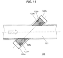
- FIG. 14 is a view showing the cross-sectional configuration of conventional ultrasonic flow rate measurement device 100.
- ultrasonic flow rate measurement device 100 is provided with flow rate measuring tube 121 that allows a fluid to be measured to flow from one side to the other side.
- ultrasonic sensor 122a is disposed on an upstream side whereas another ultrasonic sensor 122b is disposed on a downstream side, wherein ultrasonic sensors 122a and 122b are disposed opposite to each other while holding flow rate measuring tube 121 therebetween at a predetermined angle with respect to the center line.
- Ultrasonic sensors 122a and 122b are contained in recesses 125a and 125b formed in the flow rate measuring tube 121, respectively.
- Bulk-like ultrasonic wave transmitting members 123a and 123b are housed inside of recesses 125a and 125b, respectively, thereby preventing the intrusion of the fluid to be measured into recesses 125a and 125b, followed by measuring a flow rate (see, for example, Patent Literature 1).
- FIG. 15 is a view showing the cross-sectional configuration of another conventional ultrasonic flow rate measurement device 150.
- ultrasonic flow rate measurement device 150 has recesses 125a and 125b, in which ultrasonic sensors 122a and 122b are contained, respectively.
- Suppressing members 124a and 124b for restricting a fluid to be measured from flowing toward the sensors are disposed at openings, through which ultrasonic waves go onto a channel, at recesses 125a and 125b (see, for example, Patent Literature 2).
- ultrasonic wave transmitting members 123a and 123b or suppressing members 124a and 124b are provided for suppressing the fluid to be measured from flowing into recesses 125a and 125b. Consequently, the disturbance of the flow of the fluid to be measured becomes small at a measurement part (i.e., an ultrasonic wave propagation path) at flow rate measuring tube 121 and recesses 125a and 125b, thereby reducing the degradation of measurement accuracy.
- the above-described configurations require separate members, and therefore, there arises a problem of an increase in cost due to an increase in material cost or number of man-hours.
- a reception level of an ultrasonic wave in ultrasonic sensors 122a and 122b drops, and therefore, there arises a problem of difficulty of reduction of a drive input into ultrasonic sensors 122a and 122b.
- a gas meter for measuring domestic fuel gas such as town gas or LPG (liquefied petroleum gas) is kept to be used with a small battery capacity for as long a period as ten years, there arises a problem of difficulty in reducing power consumption.
- the present invention provides an ultrasonic flow rate measurement device for suppressing an increase in cost while stabilizing measurement accuracy and lowering power consumption.
- An ultrasonic flow rate measurement device includes a measurement channel, through which a fluid to be measured flows; and a sensor fixing casing having openings formed in the measurement channel and sensor fixing cavities communicating with the openings.
- the ultrasonic flow rate measurement device includes a pair of ultrasonic sensors contained in the sensor fixing cavities, for measuring the flow rate of the fluid to be measured; and a flow rate measuring unit for detecting the flow rate based on an ultrasonic wave propagation time between the pair of ultrasonic sensors.
- the ultrasonic flow rate measurement device includes a suppressing member formed at each of the openings, for suppressing the fluid to be measured from intruding into each of the sensor fixing cavities, wherein the suppressing member is molded integrally with the sensor fixing casing.
- the suppressing member for restricting a fluid from intruding into the sensor fixing cavity is molded at the same time when the sensor fixing casing is molded. Therefore, it is possible to prevent an increase in cost or an increase in the number of assembling man-hours without disposing a separate member, thus suppressing disturbance of a fluid to be measured, which may be produced in the sensor fixing cavity, so as to stabilize measurement accuracy and reduce power consumption.
- FIG. 1 is a cross-sectional view showing the configuration of ultrasonic flow rate measurement device 50 in an exemplary embodiment according to the present invention.
- hollow arrows indicate flows of a fluid (i.e., a fluid to be measured).
- ultrasonic flow rate measurement device 50 is provided with fluid supply path 3.
- Fluid supply path 3 is provided with, on the way of a channel, cutoff valve 4 including drive 4a having an electromagnet device such as a stepping motor and valve body 4b in association with drive 4a, wherein valve body 4b is adapted to open or close cutoff valve 4.
- cutoff valve 4 When cutoff valve 4 is released, a fluid to be measured is allowed to flow from fluid supply path 3 into meter casing 2.
- Ultrasonic flow rate measurement device 50 is provided with measurement channel 1, through which the fluid to be measured flows. Measurement channel 1 is formed into a rectangular shape in cross section such as a rectangle. The fluid to be measured filling up meter casing 2 flows into measurement channel 1 through inlet side 1a of measurement channel 1, and further, flows outward of meter casing 2 through fluid outflow path 6 connected to downstream side 1b of measurement channel 1.
- cutoff valve 4 is designed to be closed when the fluid abnormally flows or an earthquake is detected by a seismoscope (not shown). When cutoff valve 4 is closed, the fluid to be measured cannot flow into meter casing 2 from fluid supply path 3.
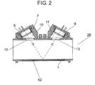
- FIG. 2 is a cross-sectional view showing flow rate measuring unit 26 in the exemplary embodiment according to the present invention.
- sensor fixing casing 7 When measurement channel 1 is formed into a rectangular shape in cross section, sensor fixing casing 7 is connected onto a short side, for example.
- a pair of ultrasonic sensors 8 and 9 constituting a flow rate detecting unit is arranged in such a manner as to transmit and receive an ultrasonic wave reflected on an opposite wall 52.
- Ultrasonic sensors 8 and 9 are contained in sensor fixing cavities 10 and 11 inclined with respect to measurement channel 1, respectively.
- An ultrasonic wave is propagated inside of measurement channel 1 through openings 12 and 13 formed at measurement channel 1 of sensor fixing casing 7 between ultrasonic sensors 8 and 9.
- suppressing members 20 At openings 12 and 13 are disposed suppressing members 20 (see FIG. 8 ) for suppressing the fluid to be measured from flowing into sensor fixing cavities 10 and 11.
- suppressing member 20 is molded integrally with sensor fixing casing 7.
- Sensor fixing cavities 10 and 11 communicate with openings 12 and 13, respectively.
- ultrasonic sensors 8 and 9 are not limited to the above-described example.
- Ultrasonic sensors 8 and 9 may be satisfactorily disposed at the same side of measurement channel 1, thus configuring an ultrasonic wave propagation path utilizing the reflection on the opposite wall. In this manner, measurement channel 1 can be reduced in size.
- Control unit 5 drives ultrasonic sensors 8 and 9, measures a propagation time of an ultrasonic wave, detects a flow rate, and further, drives cutoff valve 4 at the time of abnormality.
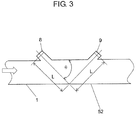
- FIG. 3 is a view explanatory of a flow rate measuring operation with an ultrasonic wave in the exemplary embodiment according to the present invention.
- ultrasonic sensors 8 and 9 are disposed on the same plane as the rectangular cross-section of measurement channel 1, thus unifying ultrasonic sensors 8 and 9 with each other.
- the propagation channel for transmitting or receiving an ultrasonic wave is formed into a V shape turned over on opposite wall 52.
- the ultrasonic wave is transmitted or received between ultrasonic sensors 8 and 9 upstream and downstream arranged, respectively.
- measurement is carried out with respect to propagation time T1 until downstream ultrasonic sensor 9 receives the ultrasonic wave emitting from upstream ultrasonic sensor 8.
- measurement is carried out with respect to propagation time T2 until upstream ultrasonic sensor 8 receives the ultrasonic wave emitting from downstream ultrasonic sensor 9.
- a flow rate is calculated in a computer in control unit 5 functioning as a flow rate measuring unit according to equations below based on propagation times T1 and T2 measured in the above-described manner.
- the flow rate measuring unit detects the flow rate of a fluid to be measured based on the propagation times of the ultrasonic waves transmitted and received between ultrasonic sensors 8 and 9.
- Reference character V represents a flow rate of a fluid to be measured in a flow direction of measurement channel 1.
- reference symbol ⁇ denotes an angle formed between the flow direction of measurement channel 1 and an ultrasonic wave propagation path
- 2 x L a distance of the ultrasonic wave propagation path between ultrasonic sensors 8 and 9
- C a velocity of sound of the fluid to be measured
- flow rate V is calculated based on the following equations.
- T ⁇ 1 2 x L / C + Vcos ⁇
- T ⁇ 2 2 x L / C ⁇ Vcos ⁇
- Equation (3) ( 2 x L / 2 ⁇ cos ⁇ ) 1 / T ⁇ 1 - 1 / T ⁇ 2
- flow rate V can be calculated based on propagation times T1 and T2.
- angle ⁇ is 45°
- distance L is 35 mm
- velocity C of sound is 340 m/s
- flow rate V is 8 m/s
- T1 is 2.0 x 10 -4 sec.
- T2 is 2.1 x 10 -4 sec. In other words, instant measurement can be achieved.
- the ultrasonic wave propagation path between ultrasonic sensors 8 and 9 is not always limited to the above-described V-shaped propagation path.
- a flow rate can be also measured as long as a propagation path traverses measurement channel 1 at least once and the propagation time of an ultrasonic wave depends upon a change in flow rate.
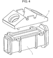
- FIG. 4 is an exploded perspective view showing the configuration of flow rate measuring unit 26 in the exemplary embodiment according to the present invention.
- flow rate measuring unit 26 is constituted of two molded parts: namely, sensor fixing casing 7 and measurement channel 1.
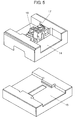
- FIG. 5 is a perspective view showing the configuration of a die for use in molding sensor fixing casing 7 in the exemplary embodiment according to the present invention.
- a die for molding sensor fixing casing 7 is constituted of upper die 14 and lower die 15.
- Upper die 14 includes slider dies 16 and 17 for forming cavities, in which ultrasonic sensors 8 and 9 are contained.
- Sensor fixing cavities 10 and 11 and openings 12 and 13 are molded with slider dies 16 and 17, respectively.
- FIG. 6 is a diagram illustrating the result of the fluid analysis of a flow of a fluid to be measured in the case where no suppressing member is disposed at opening 12 of an ultrasonic wave propagating portion in the exemplary embodiment according to the present invention.
- a large vortex is produced in sensor fixing cavity 10 as a clearance defined between ultrasonic sensor 8 and measurement channel 1.
- the vortex disturbs the ultrasonic wave. Consequently, a propagation time to be measured has an error, and therefore, it is difficult to accurately measure the flow rate of the fluid passing measurement channel 1.
- Sensor fixing casing 7 in the exemplary embodiment according to the present invention is fabricated by using a molding method with a die.
- sensor fixing cavities 10 and 11 for use in fixing the sensors are integrally molded by inserting auxiliary dies, that is, slider dies 16 and 17 into the dies for molding a sensor fixing body.
- FIG. 7 is a perspective view showing the configuration of slider dies 16 and 17 in a first exemplary embodiment according to the present invention.
- FIG. 8 is a perspective view showing the configuration of sensor fixing casing 7 in the first exemplary embodiment according to the present invention.
- each of slider dies 16 and 17 has flat portion 18 in abutment against lower die 15 at the tip thereof so as to form each of openings 12 and 13.
- Flat portion 18 is constituted of the same plane as the wall surface of measurement channel 1 continuous to each of openings 12 and 13. Consequently, the wall surface of measurement channel 1 can be integrated with suppressing member 20 at openings 12 and 13, so as to produce a smooth flow inside of measurement channel 1, thus stably measuring the flow rate.
- flat portion 18 has a plurality of slits 19 that are linear and perpendicular with respect to the flow of the fluid to be measured inside of measurement channel 1.
- slit 19 is constituted such that the depth direction thereof is perpendicular to an ultrasonic wave emission surface of each of ultrasonic sensors 8 and 9.
- Suppressing member 20 is constituted of slits 19 formed at the tip of each of slider dies 16 and 17.
- casing constituting material intrudes into slits 19 when sensor fixing casing 7 is molded, so that suppressing member 20 for suppressing the intrusion of the fluid to be measured can be integrally formed in sensor fixing cavity 10. Additionally, the intrusion of the fluid to be measured can be suppressed as much as possible, and further, an adverse influence on attenuation of the ultrasonic propagation can be reduced.
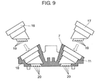
- FIG. 9 is a view illustrating the relationship between sensor fixing casing 7 and slider dies 16 and 17 in the first exemplary embodiment according to the present invention.
- FIG. 9 illustrates the relationship between the cross-sectional configuration of sensor fixing casing 7 shown in FIG. 8 and the side surfaces of slider dies 16 and 17.
- molding with slider dies 16 and 17 enables suppressing members 20 to be constituted at positions corresponding to slits 19 formed at slider dies 16 and 17 in sensor fixing casing 7.
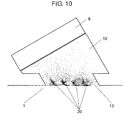
- FIG. 10 is a diagram illustrating the result of a fluid analysis with an advantage of suppressing member 20 in the first exemplary embodiment according to the present invention.
- the disturbance of the flow such as the vortex can be eliminated in sensor fixing cavity 10 formed at ultrasonic sensor 8 in comparison with the case where no suppressing member 20 is disposed at opening 12 illustrated in FIG. 6 .
- the function of suppressing member 20 is fulfilled in the same manner at sensor fixing cavity 11 formed at ultrasonic sensor 9.
- FIG. 11 is a perspective view showing the configuration of slider die 32 in a second exemplary embodiment according to the present invention.
- FIG. 12 is a perspective view showing the configuration of sensor fixing casing 7 in the second exemplary embodiment according to the present invention.
- ultrasonic flow rate measurement device 50 and a die in the present exemplary embodiment are the same as those in the first exemplary embodiment except the configuration of slider die 32, and therefore, their explanations will be omitted.
- grid-like slits 33 are formed at the tip of slider die 32 in the present exemplary embodiment.
- Slits 33 are formed perpendicularly to a flow inside of measurement channel 1.
- Slits 33 are configured such that their depth direction is perpendicular to the ultrasonic wave emission surfaces of a pair of ultrasonic sensors 8 and 9.
- Grid-like suppressing member 34 after being molded is opened perpendicularly to transmission surfaces of ultrasonic sensors 8 and 9, so that the disturbance of a flow such as a vortex produced at openings 12 and 13 can be dispersed less largely, thus restricting intrusion of a fluid to be measured with better performance.
- Sensor fixing casing 7 is molded with slider die 32 in the same manner as that in the first exemplary embodiment.
- grid-like suppressing member 34 shown in FIG. 12 can be formed integrally with sensor fixing casing 7, thus further producing the effect of suppressing the disturbance of the fluid to be measured at sensor fixing cavities 10 and 11.
- a dyadic configuration constituted of measurement channel 1 and sensor fixing casing 7 is essential when a separate intrusion suppressing member such as wire netting is needed, like in the conventional apparatus.
- sensor fixing casing 7 and measurement channel 1 can be molded integrally with each other.
- sensor fixing casing 7 and measurement channel 1 are constituted as a single unit.
- the integral molding can eliminate variations in accuracy due to assembling work so as to further achieve highly accurate measurement.
- the above-described detailed specifications may depend upon the configuration of measurement channel 1.
- the present invention is not limited to the above-described exemplary embodiments.
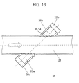
- FIG. 13 is a view showing the cross-sectional configuration of ultrasonic flow rate measurement device 54 in the second exemplary embodiment according to the present invention by way of another example.
- ultrasonic flow rate measurement device 54 is provided with flow rate measuring tube 21 (i.e., a measurement channel) that allows a fluid to be measured to flow from one side to the other side.
- flow rate measuring tube 21 i.e., a measurement channel
- ultrasonic sensor 22a is disposed on an upstream side
- another ultrasonic sensor 22b is disposed on a downstream side, wherein ultrasonic sensors 22a and 22b are disposed opposite to each other while holding flow rate measuring tube 21 therebetween at a predetermined angle with respect to the center line.
- Ultrasonic sensors 22a and 22b are contained in recesses (i.e., sensor fixing cavities) 25a and 25b formed in flow rate measuring tube 21, respectively.
- the above-described suppressing member 20 or 34 may be integrated with flow rate measuring tube 21 at an opening continuous to flow rate measuring tube 21, of each of recesses 25a and 25b. In this manner, it is possible to prevent the fluid to be measured from intruding into recesses 25a and 25b, so as to measure the flow rate with high accuracy.
- the suppressing member for suppressing the fluid to be measured from intruding into the sensor fixing cavity is formed at the same time when the casing is molded.
- the aperture of the opening can be more enlarged. Consequently, the suppressing member hardly interferes with the ultrasonic wave that passes, and further, sensitivity in transmitting and receiving the ultrasonic wave is hardly degraded.
- the drive input for the ultrasonic sensor can be reduced, thus reducing power consumption.
- the ultrasonic flow rate measurement device is useful as an ultrasonic flow rate measurement device for measuring the flow rate of various kinds of fluids in addition to a gas meter.
Landscapes
- Physics & Mathematics (AREA)
- Fluid Mechanics (AREA)
- General Physics & Mathematics (AREA)
- Electromagnetism (AREA)
- Measuring Volume Flow (AREA)
Applications Claiming Priority (2)
| Application Number | Priority Date | Filing Date | Title |
|---|---|---|---|
| JP2011083297 | 2011-04-05 | ||
| PCT/JP2012/002334 WO2012137489A1 (fr) | 2011-04-05 | 2012-04-04 | Débitmètre à ultrasons |
Publications (2)
| Publication Number | Publication Date |
|---|---|
| EP2696174A1 true EP2696174A1 (fr) | 2014-02-12 |
| EP2696174A4 EP2696174A4 (fr) | 2014-08-27 |
Family
ID=46968898
Family Applications (1)
| Application Number | Title | Priority Date | Filing Date |
|---|---|---|---|
| EP12767854.8A Withdrawn EP2696174A4 (fr) | 2011-04-05 | 2012-04-04 | Débitmètre à ultrasons |
Country Status (5)
| Country | Link |
|---|---|
| US (1) | US9372105B2 (fr) |
| EP (1) | EP2696174A4 (fr) |
| JP (1) | JPWO2012137489A1 (fr) |
| CN (1) | CN103459988B (fr) |
| WO (1) | WO2012137489A1 (fr) |
Cited By (2)
| Publication number | Priority date | Publication date | Assignee | Title |
|---|---|---|---|---|
| EP3485233B1 (fr) * | 2016-07-13 | 2020-06-03 | GWF MessSysteme AG | Débitmètre ultrasonore équipé d'un canal de mesure |
| WO2022079213A1 (fr) | 2020-10-14 | 2022-04-21 | Gwf Messsysteme Ag | Débitmètre |
Families Citing this family (15)
| Publication number | Priority date | Publication date | Assignee | Title |
|---|---|---|---|---|
| JP2012103087A (ja) * | 2010-11-10 | 2012-05-31 | Panasonic Corp | 超音波流量計測ユニット |
| US9568347B2 (en) | 2012-08-22 | 2017-02-14 | Apator Miitors Aps | Ultrasonic flow meter including a meter housing insert having transducer recesses with slanted bottom walls |
| JP2014077750A (ja) * | 2012-10-12 | 2014-05-01 | Panasonic Corp | 超音波メータ |
| JP6368916B2 (ja) * | 2015-04-16 | 2018-08-08 | パナソニックIpマネジメント株式会社 | 流量計測装置 |
| CN109074241A (zh) * | 2016-03-21 | 2018-12-21 | 恩威罗菲特国际股份有限公司 | 液化石油气供应方法及系统 |
| EP3376177B1 (fr) * | 2017-03-14 | 2019-11-20 | Endress + Hauser Flowtec AG | Débitmètre à ultrasons |
| EP3612802B1 (fr) * | 2017-04-20 | 2023-10-25 | Siemens Schweiz AG | Débitmètre du type ultrasonore |
| CN110573843A (zh) * | 2017-05-22 | 2019-12-13 | 松下知识产权经营株式会社 | 气量计 |
| DE102017130976A1 (de) * | 2017-12-21 | 2019-06-27 | Endress+Hauser Flowtec Ag | Clamp-On-Ultraschall-Durchflussmessgerät und Verfahren zum Justieren des Clamp-On-Ultraschall-Durchflussmessgeräts |
| JP2019196968A (ja) * | 2018-05-09 | 2019-11-14 | アズビル金門株式会社 | 超音波流量計 |
| EP3805712B1 (fr) * | 2018-06-08 | 2022-10-19 | Panasonic Intellectual Property Management Co., Ltd. | Dispositif de sécurité de gaz |
| EP3588017A1 (fr) * | 2018-06-27 | 2020-01-01 | Sensus Spectrum LLC | Dispositif de mesure par ultrasons |
| JP2020024180A (ja) * | 2018-08-09 | 2020-02-13 | パナソニックIpマネジメント株式会社 | 超音波流量計 |
| JP7223956B2 (ja) * | 2018-08-31 | 2023-02-17 | パナソニックIpマネジメント株式会社 | 超音波流量計 |
| CN113295222A (zh) * | 2020-02-21 | 2021-08-24 | 北京昌民技术有限公司 | 超声波流量计 |
Citations (3)
| Publication number | Priority date | Publication date | Assignee | Title |
|---|---|---|---|---|
| EP1182431A1 (fr) * | 1999-03-17 | 2002-02-27 | Matsushita Electric Industrial Co., Ltd. | Debitmetre a ultrasons |
| EP1612520A1 (fr) * | 2003-02-24 | 2006-01-04 | Matsushita Electric Industrial Co., Ltd. | Dispositif de mesure de fluides a ultrasons |
| EP1867964A1 (fr) * | 2006-06-12 | 2007-12-19 | Hitachi, Ltd. | Instrument de mesure de débit, passage de mesure de débit et procédé de production |
Family Cites Families (15)
| Publication number | Priority date | Publication date | Assignee | Title |
|---|---|---|---|---|
| JPS54116179A (en) | 1978-03-01 | 1979-09-10 | Kunihiko Kanda | Method of forming electric wire |
| JPS6326537A (ja) | 1986-07-18 | 1988-02-04 | Kawasaki Steel Corp | 超音波流量計 |
| SK95995A3 (en) * | 1993-01-30 | 1995-12-06 | Cambridge Consultants | Flow indicator |
| JP3824236B2 (ja) | 1999-03-17 | 2006-09-20 | 松下電器産業株式会社 | 超音波流量計測装置 |
| CN1293369C (zh) * | 1999-06-24 | 2007-01-03 | 松下电器产业株式会社 | 流量计 |
| ATE513188T1 (de) * | 2003-04-28 | 2011-07-15 | Panasonic Corp | Ultraschallempfänger |
| KR100861827B1 (ko) * | 2003-11-10 | 2008-10-07 | 마츠시타 덴끼 산교 가부시키가이샤 | 초음파 유량계와 그 제조 방법 |
| JP2006090952A (ja) * | 2004-09-27 | 2006-04-06 | Saginomiya Seisakusho Inc | 超音波流量計およびその製造方法 |
| DE102004060065B4 (de) * | 2004-12-14 | 2016-10-20 | Robert Bosch Gmbh | Ultraschall Durchflussmesser mit Leitelementen |
| TW200739039A (en) * | 2005-08-12 | 2007-10-16 | Celerity Inc | Ultrasonic flow sensor |
| DE102005038599A1 (de) * | 2005-08-16 | 2007-02-22 | Robert Bosch Gmbh | Ultraschallmesseinheit mit integrierter Feuchteermittlung |
| JP4986748B2 (ja) * | 2007-07-09 | 2012-07-25 | パナソニック株式会社 | 超音波式流体計測装置の多層流路部材 |
| US8161824B2 (en) | 2007-07-09 | 2012-04-24 | Panasonic Corporation | Multilayer flow path member of ultrasonic fluid measurement apparatus and ultrasonic fluid measurement apparatus |
| JP2009288151A (ja) * | 2008-05-30 | 2009-12-10 | Ricoh Elemex Corp | 超音波流量計 |
| EP2351994A4 (fr) * | 2008-12-18 | 2017-12-27 | Panasonic Corporation | Débitmètre à ultrasons |
-
2012
- 2012-04-04 JP JP2013508766A patent/JPWO2012137489A1/ja active Pending
- 2012-04-04 CN CN201280016739.0A patent/CN103459988B/zh active Active
- 2012-04-04 US US13/984,633 patent/US9372105B2/en active Active
- 2012-04-04 EP EP12767854.8A patent/EP2696174A4/fr not_active Withdrawn
- 2012-04-04 WO PCT/JP2012/002334 patent/WO2012137489A1/fr active Application Filing
Patent Citations (3)
| Publication number | Priority date | Publication date | Assignee | Title |
|---|---|---|---|---|
| EP1182431A1 (fr) * | 1999-03-17 | 2002-02-27 | Matsushita Electric Industrial Co., Ltd. | Debitmetre a ultrasons |
| EP1612520A1 (fr) * | 2003-02-24 | 2006-01-04 | Matsushita Electric Industrial Co., Ltd. | Dispositif de mesure de fluides a ultrasons |
| EP1867964A1 (fr) * | 2006-06-12 | 2007-12-19 | Hitachi, Ltd. | Instrument de mesure de débit, passage de mesure de débit et procédé de production |
Non-Patent Citations (1)
| Title |
|---|
| See also references of WO2012137489A1 * |
Cited By (7)
| Publication number | Priority date | Publication date | Assignee | Title |
|---|---|---|---|---|
| EP3485233B1 (fr) * | 2016-07-13 | 2020-06-03 | GWF MessSysteme AG | Débitmètre ultrasonore équipé d'un canal de mesure |
| EP3485234B1 (fr) * | 2016-07-13 | 2020-07-01 | GWF MessSysteme AG | Débitmètre équipé d'un canal de mesure |
| US10704941B2 (en) | 2016-07-13 | 2020-07-07 | Gwf Messsysteme Ag | Flow meter with measuring channel |
| US10746580B2 (en) | 2016-07-13 | 2020-08-18 | Gwf Messsysteme Ag | Flow meter with measuring channel |
| EP3734236A1 (fr) | 2016-07-13 | 2020-11-04 | GWF MessSysteme AG | Débitmètre pourvu de canal de mesure |
| WO2022079213A1 (fr) | 2020-10-14 | 2022-04-21 | Gwf Messsysteme Ag | Débitmètre |
| WO2022079214A1 (fr) | 2020-10-14 | 2022-04-21 | Gwf Messsysteme Ag | Débitmètre |
Also Published As
| Publication number | Publication date |
|---|---|
| WO2012137489A1 (fr) | 2012-10-11 |
| CN103459988A (zh) | 2013-12-18 |
| CN103459988B (zh) | 2016-08-17 |
| US20130312537A1 (en) | 2013-11-28 |
| JPWO2012137489A1 (ja) | 2014-07-28 |
| EP2696174A4 (fr) | 2014-08-27 |
| US9372105B2 (en) | 2016-06-21 |
Similar Documents
| Publication | Publication Date | Title |
|---|---|---|
| EP2696174A1 (fr) | Débitmètre à ultrasons | |
| EP3485234B1 (fr) | Débitmètre équipé d'un canal de mesure | |
| EP2351994A1 (fr) | Débitmètre à ultrasons | |
| EP1816442A3 (fr) | Débitmètre à ultrasons | |
| US7380470B2 (en) | Ultrasonic flow meter including turbulators | |
| US7823463B1 (en) | Ultrasonic flow sensor using two streamlined probes | |
| EP2639560A1 (fr) | Dispositif de mesure de débit par ultrasons | |
| EP2657657A1 (fr) | Débitmètre ultrasonique | |
| EP2799819A1 (fr) | Procédé de réglage d'un dispositif de mesure de débit et dispositif de mesure du débit | |
| EP2908103A1 (fr) | Débitmètre | |
| EP3845866A1 (fr) | Débitmètre à ultrasons | |
| EP3012593B1 (fr) | Dispositif de débitmètre à ultrasons | |
| CN110553690B (zh) | 流体测量装置和用于流体测量装置的流体测量模块及组件 | |
| CN108463693B (zh) | 气量计 | |
| EP2733471A1 (fr) | Débitmètre à ultrasons | |
| EP3285047A1 (fr) | Dispositif de mesure de débit | |
| JP2014215060A (ja) | 流量計測装置 | |
| EP2485017A1 (fr) | Débitmètre à ultrasons | |
| EP3835734A1 (fr) | Débitmètre ultrasonore | |
| JP4455000B2 (ja) | ガスメータ | |
| CN109238384B (zh) | 用于流体的测量装置以及具有测量装置的流体系统 | |
| JP5816831B2 (ja) | 超音波流量計 | |
| JP6134899B2 (ja) | 流量計測ユニット | |
| JP2014077750A (ja) | 超音波メータ | |
| JP6306434B2 (ja) | 超音波流量計 |
Legal Events
| Date | Code | Title | Description |
|---|---|---|---|
| PUAI | Public reference made under article 153(3) epc to a published international application that has entered the european phase |
Free format text: ORIGINAL CODE: 0009012 |
|
| 17P | Request for examination filed |
Effective date: 20130806 |
|
| AK | Designated contracting states |
Kind code of ref document: A1 Designated state(s): AL AT BE BG CH CY CZ DE DK EE ES FI FR GB GR HR HU IE IS IT LI LT LU LV MC MK MT NL NO PL PT RO RS SE SI SK SM TR |
|
| DAX | Request for extension of the european patent (deleted) | ||
| A4 | Supplementary search report drawn up and despatched |
Effective date: 20140724 |
|
| RIC1 | Information provided on ipc code assigned before grant |
Ipc: G01F 15/14 20060101ALN20140718BHEP Ipc: G01F 1/66 20060101AFI20140718BHEP |
|
| 17Q | First examination report despatched |
Effective date: 20160223 |
|
| STAA | Information on the status of an ep patent application or granted ep patent |
Free format text: STATUS: THE APPLICATION IS DEEMED TO BE WITHDRAWN |
|
| 18D | Application deemed to be withdrawn |
Effective date: 20160705 |