EP2696060A1 - Procédé d'apprentissage de la quantité d'injection de carburant pour moteur à combustion interne - Google Patents
Procédé d'apprentissage de la quantité d'injection de carburant pour moteur à combustion interne Download PDFInfo
- Publication number
- EP2696060A1 EP2696060A1 EP13163679.7A EP13163679A EP2696060A1 EP 2696060 A1 EP2696060 A1 EP 2696060A1 EP 13163679 A EP13163679 A EP 13163679A EP 2696060 A1 EP2696060 A1 EP 2696060A1
- Authority
- EP
- European Patent Office
- Prior art keywords
- learning
- threshold value
- learning control
- controller
- internal combustion
- Prior art date
- Legal status (The legal status is an assumption and is not a legal conclusion. Google has not performed a legal analysis and makes no representation as to the accuracy of the status listed.)
- Withdrawn
Links
Images


Classifications
-
- F—MECHANICAL ENGINEERING; LIGHTING; HEATING; WEAPONS; BLASTING
- F02—COMBUSTION ENGINES; HOT-GAS OR COMBUSTION-PRODUCT ENGINE PLANTS
- F02D—CONTROLLING COMBUSTION ENGINES
- F02D41/00—Electrical control of supply of combustible mixture or its constituents
- F02D41/02—Circuit arrangements for generating control signals
- F02D41/14—Introducing closed-loop corrections
- F02D41/1497—With detection of the mechanical response of the engine
-
- F—MECHANICAL ENGINEERING; LIGHTING; HEATING; WEAPONS; BLASTING
- F02—COMBUSTION ENGINES; HOT-GAS OR COMBUSTION-PRODUCT ENGINE PLANTS
- F02D—CONTROLLING COMBUSTION ENGINES
- F02D41/00—Electrical control of supply of combustible mixture or its constituents
- F02D41/24—Electrical control of supply of combustible mixture or its constituents characterised by the use of digital means
- F02D41/2406—Electrical control of supply of combustible mixture or its constituents characterised by the use of digital means using essentially read only memories
- F02D41/2425—Particular ways of programming the data
- F02D41/2429—Methods of calibrating or learning
- F02D41/2441—Methods of calibrating or learning characterised by the learning conditions
-
- F—MECHANICAL ENGINEERING; LIGHTING; HEATING; WEAPONS; BLASTING
- F02—COMBUSTION ENGINES; HOT-GAS OR COMBUSTION-PRODUCT ENGINE PLANTS
- F02D—CONTROLLING COMBUSTION ENGINES
- F02D41/00—Electrical control of supply of combustible mixture or its constituents
- F02D41/24—Electrical control of supply of combustible mixture or its constituents characterised by the use of digital means
- F02D41/2406—Electrical control of supply of combustible mixture or its constituents characterised by the use of digital means using essentially read only memories
- F02D41/2425—Particular ways of programming the data
- F02D41/2429—Methods of calibrating or learning
- F02D41/2451—Methods of calibrating or learning characterised by what is learned or calibrated
- F02D41/2464—Characteristics of actuators
- F02D41/2467—Characteristics of actuators for injectors
-
- F—MECHANICAL ENGINEERING; LIGHTING; HEATING; WEAPONS; BLASTING
- F02—COMBUSTION ENGINES; HOT-GAS OR COMBUSTION-PRODUCT ENGINE PLANTS
- F02D—CONTROLLING COMBUSTION ENGINES
- F02D2200/00—Input parameters for engine control
- F02D2200/02—Input parameters for engine control the parameters being related to the engine
- F02D2200/04—Engine intake system parameters
- F02D2200/0414—Air temperature
-
- F—MECHANICAL ENGINEERING; LIGHTING; HEATING; WEAPONS; BLASTING
- F02—COMBUSTION ENGINES; HOT-GAS OR COMBUSTION-PRODUCT ENGINE PLANTS
- F02D—CONTROLLING COMBUSTION ENGINES
- F02D2200/00—Input parameters for engine control
- F02D2200/02—Input parameters for engine control the parameters being related to the engine
- F02D2200/06—Fuel or fuel supply system parameters
- F02D2200/0602—Fuel pressure
-
- F—MECHANICAL ENGINEERING; LIGHTING; HEATING; WEAPONS; BLASTING
- F02—COMBUSTION ENGINES; HOT-GAS OR COMBUSTION-PRODUCT ENGINE PLANTS
- F02D—CONTROLLING COMBUSTION ENGINES
- F02D2200/00—Input parameters for engine control
- F02D2200/02—Input parameters for engine control the parameters being related to the engine
- F02D2200/06—Fuel or fuel supply system parameters
- F02D2200/0606—Fuel temperature
-
- F—MECHANICAL ENGINEERING; LIGHTING; HEATING; WEAPONS; BLASTING
- F02—COMBUSTION ENGINES; HOT-GAS OR COMBUSTION-PRODUCT ENGINE PLANTS
- F02D—CONTROLLING COMBUSTION ENGINES
- F02D2200/00—Input parameters for engine control
- F02D2200/02—Input parameters for engine control the parameters being related to the engine
- F02D2200/10—Parameters related to the engine output, e.g. engine torque or engine speed
- F02D2200/101—Engine speed
-
- F—MECHANICAL ENGINEERING; LIGHTING; HEATING; WEAPONS; BLASTING
- F02—COMBUSTION ENGINES; HOT-GAS OR COMBUSTION-PRODUCT ENGINE PLANTS
- F02D—CONTROLLING COMBUSTION ENGINES
- F02D2200/00—Input parameters for engine control
- F02D2200/70—Input parameters for engine control said parameters being related to the vehicle exterior
- F02D2200/703—Atmospheric pressure
-
- F—MECHANICAL ENGINEERING; LIGHTING; HEATING; WEAPONS; BLASTING
- F02—COMBUSTION ENGINES; HOT-GAS OR COMBUSTION-PRODUCT ENGINE PLANTS
- F02D—CONTROLLING COMBUSTION ENGINES
- F02D41/00—Electrical control of supply of combustible mixture or its constituents
- F02D41/02—Circuit arrangements for generating control signals
- F02D41/04—Introducing corrections for particular operating conditions
- F02D41/12—Introducing corrections for particular operating conditions for deceleration
- F02D41/123—Introducing corrections for particular operating conditions for deceleration the fuel injection being cut-off
Definitions
- the present invention relates to a learning method related to a fuel injection amount of an internal combustion engine.
- an injector injects an amount of fuel during non-injection operation of the internal combustion engine to observe the behavior of the internal combustion engine. In this way, it can obtain a required correction amount for the injector.
- a diesel engine configured to perform pilot injection has conventionally been known.
- the injector injects high-pressure fuel into a cylinder.
- pilot injection occurs, i.e., a minute amount of fuel is injected, that is. This helps to relieve combustion noise and to suppress NOx. To obtain the above result to a sufficient degree, it is necessary to accurately determine the amount injected during the pilot injection.
- injection for learning (single-shot injection) from the injector is executed during non-injection operation, in which the command injection amount of the internal combustion engine is zero or less.
- “Command injection” refers to the amount of fuel programmed by a user to be injected.
- the torque generated is calculated based on the RPM of the internal combustion engine and the amount of fluctuation in the RPM of the internal combustion engine during this control period.
- the actual injection amount is estimated from the calculated amount of torque.
- a deviation amount between the estimated actual injection amount and the command injection amount used for learning is obtained in order to calculate the correction amount.
- the fluctuation amount of the RPM of the internal combustion engine is used. Consequently, if the surrounding conditions of the internal combustion engine during the learning control are not constant, it may not be possible to obtain an accurate correction amount.
- an environmental correction amount is calculated. This amount corresponds to the change in the operational environmental conditions of the internal combustion engine.
- the actual injection amount estimated through the learning control is corrected. As a result, it is possible to obtain a more accurate injector correction amount.
- the learning control is not executed when the execution condition for the learning control is not satisfied. For example, when the circulating water temperature of the internal combustion engine is lower than a predetermined temperature (i.e., during warming up), the learning control is not executed.
- the internal combustion typically ends before the warming-up operation has been completed.
- the circulating water temperature does not attain the predetermined temperature level, and the learning control is not executed.
- the learning control is not executed, it is impossible to obtain an appropriate correction amount for the injector.
- the deviation amount of the injection amount of the injector also fluctuates, so that, in some cases, even when pilot injection is performed, it is impossible to obtain a reduction in combustion noise and suppression of NOx as desired.
- a fuel injection amount learning method for an internal combustion engine In the method, injection for learning is executed from an injector during atypical operation of the internal combustion engine, and learning control is executed with timing. In the learning control, a correction amount for the injector is obtained based on an RPM fluctuation amount of the internal combustion engine due to the injection for learning and on the RPM of the internal combustion engine.
- the learning method includes a learning condition determination step, a learning execution step, a learning frequency determination step, and a learning frequency increase step.
- a controller determines whether or not a learning control execution condition is satisfied with a predetermined condition with the timing.
- the learning control is executed in the learning execution step.
- the controller obtains a learning control execution frequency.
- the learning control execution frequency is forcibly increased in the learning frequency increase step.
- the fuel injection amount learning method for the internal combustion engine may further include an initial period determination step.
- the controller determines whether or not an accumulation period (obtained from the brand-new state of the injector) is within a predetermined initial period.
- a threshold value of the predetermined condition is changed so as to relieve the execution condition in the learning frequency increase step.
- a change in the deviation amount of the injection amount of the injector is particularly large.
- the execution frequency has not attained a predetermined frequency
- the threshold value for determining the execution condition for the learning control is changed so as to relieve the execution condition.
- a fuel injection amount learning method for an internal combustion engine may include a learning condition determination step, a learning execution step, and a learning frequency increase step.
- a controller determines whether or not a learning control execution condition is satisfied with a predetermined condition with the timing.
- the learning control is executed when the controller determines that the execution condition is satisfied with the predetermined condition in the learning condition determination step.
- a threshold value is changed according to the fuel injection pressure from the injector. The threshold value is for determining whether or not the execution condition in the learning condition determination step is satisfied.
- the determination of the execution condition in the learning condition determination step may include a determination of the circulating water temperature of the internal combustion engine and a determination of the atmospheric pressure.
- the threshold value for the determination of the circulating water temperature and the threshold value for the determination of the atmospheric pressure in the learning condition determination step may be changed.
- the execution condition determination in the learning condition determination step may include the determination of the circulating water temperature of the internal combustion engine, the determination of the atmospheric pressure, a determination of the temperature of the intake air of the internal combustion engine, and a determination of the fuel temperature.
- the learning frequency increase step at least one of the following threshold values which are used in the learning condition determination step, may be changed: a threshold value of the circulating water temperature, a threshold value of the atmospheric pressure, a threshold value for the determination of the intake air temperature, and a threshold value for the determination of the fuel temperature.
- FIG. 1 shows an internal combustion engine 10 consisting, for example, of a diesel engine.
- the engine 10 has cylinders 45A to 45D.
- An intake pipe 11 and an exhaust pipe 12 are connected to the engine 10.
- Intake air is introduced into the cylinders 45A to 45D from the intake pipe 11, and exhaust gas from the cylinders 45A to 45D is discharged to the exhaust pipe 12.
- the intake pipe 11 may be provided with an intake air temperature detection sensor (intake air temperature detection means) 24.
- a controller 30 can detect the temperature of the intake air based on a detection signal from the intake air temperature detection sensor 24.
- the engine 10 may be provided with a rotation detection sensor (rotation detection means) 26.
- the rotation sensor 26 can detect an RPM of the internal combustion engine (e.g., RPM of a crankshaft), a rotational angle (e.g., a compression top dead center timing of each cylinder), etc.
- the controller 30 can detect the RPM, the rotational angle, etc. of the engine 10 based on a detection signal from the rotation sensor 26.
- the engine 10 may be provided with a circulating water temperature detection sensor (circulation water temperature detection means) 22.
- the controller 30 can detect the circulating water temperature of the engine 10 based on a detection signal from the circulating water temperature detection sensor 22.
- the controller 30 can detect an atmospheric pressure based on a detection signal from an atmospheric pressure sensor (atmospheric pressure detection means) provided, for example, on the controller 30.
- Fuel is supplied to a common rail 41 from a fuel tank (not shown).
- the fuel in the common rail 41 is maintained at high pressure, and is supplied to injectors 43A to 43D via fuel pipes 42A to 42D.
- the common rail 41 is provided with a fuel pressure sensor (fuel pressure detection means) 21 and a fuel temperature sensor (fuel temperature detection means) 25.
- the controller 30 can detect the pressure of the fuel in the common rail 41 based on a detection signal from the fuel pressure sensor 21.
- the controller 30 can detect the fuel temperature in the common rail 41 based on a detection signal from the fuel temperature sensor 25.
- Injectors 43A to 43D are provided on the cylinders 45A to 45D, respectively, and are configured to inject a predetermined amount of fuel into the cylinders with a predetermined timing in response to a control signal from the controller 30.
- the controller 30 takes in detection signals from various sensors, detects an operational condition of the engine 10, and outputs a control signal for driving the injectors 43A to 43D.
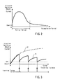
- FIG. 2 shows a deviation amount of an injection amount with respect to an accumulation period in the injectors 43A to 43D.
- the injection deviation amount is a deviation amount between the injection amount as commanded by the controller 30 (command injection amount) and the actual injection amount.
- the injection deviation amount undergoes a relatively great change during the initial period.
- the deviation amount after an elapse of the initial period is smaller than that during the initial period.
- the initial period occurs during the start of the use of the injector when the accumulation period is not more than a predetermined period. That is, the initial period is a period in which the accumulation period from a brand-new state is not more than a predetermined period.
- determining the initial period there is estimated, for example, a temperature at which an injector nozzle is heated during the operation of the internal combustion engine. According to an operation continuation time, additional values corresponding to the nozzle heating temperature may be accumulated. When the accumulation value is not more than a predetermined value, it is determined that the engine is in the initial period.
- FIG. 3 shows a change in the injection deviation amount from the injector corresponding to a traveling distance, and a learning control effect. As shown in FIG. 3 , each time the traveling distance reaches a predetermined distance, the controller 30 determines that the learning timing has been attained, and executes the learning control with the learning timing.
- the controller 30 executes learning injection (single-shot injection) from the injector.
- a generation torque is calculated based on the fluctuation amount of the RPM of the internal combustion engine, which has been increased through the learning injection, and the RPM of the internal combustion engine.
- the actual injection amount is estimated from the generation torque calculated.
- a deviation amount is obtained from the difference between the estimated actual injection amount and the command injection amount of the learning injection. This deviation amount is used in calculating a correction amount.
- a line A1 indicates the deviation amount in the situation where the correction of the injection amount of the injector through the learning control is not executed.
- the line A1 substantially coincides with the deviation amount in the first half of the initial period shown in FIG. 2 .
- a line B1 indicates the deviation amount in the case where the injection deviation amount of the injector is corrected through the above-mentioned learning control with the learning timing. Each time the learning control is performed, the deviation amount is reduced to a level G1.
- the level G1 corresponds, for example, to an error in the correction amount obtained through the learning control.
- the learning control when the learning control is consistently executed, it is possible to appropriately correct the deviation amount of the injector. However, if the learning timing has been attained, the learning control is not always executed. For, in a conventional learning control, a determination of the execution condition is made before it is determined that the learning timing has been attained and the learning control is performed. In the determination of the execution condition, it is determined whether the learning control may be executed or not. The controller is programmed so as not to execute the learning control in the case where the execution condition is not satisfied, for example, an environment in which the combustion of the injected fuel is not stable.
- the learning control is a very effective means for correcting the injection deviation amount of the injector.
- an erroneous learning control should be performed, it is impossible to make an effective correction until the next learning timing.
- the determination of the execution condition is somewhat strict. For example, when a short-range operation in which the warming-up operation is not completed is repeated, there is a possibility of a circulating water temperature, etc. not satisfying the execution condition. Thus, even if the learning timing has been attained, there is the possibility of continuation in a state in which the learning control is not executed. In the fuel injection amount learning method for the internal combustion engine according to the present invention, even when such a state continues and the execution condition is appropriately satisfied as described below, it is possible to execute the learning control.
- the learning control is executed during the initial period.
- the deviation amount of the injection amount of the injector is large.
- imprecision in the correction amount is allowed so long as it is within the permissible range, and the learning control is executed.
- the controller 30 executes a processing of a flowchart in FIG. 4 at each predetermined period of time (which, for example, is several ms to several hundred ms).
- step S10 the controller 30 determines whether or not it is the learning timing. When it is the learning timing (YES in step S10), the procedure advances to step S11. When it is not the learning timing (NO in step S10), the processing is completed. The controller 30 determines that it is the learning timing when, for example, the traveling distance from the previous learning timing has reached a predetermined distance.
- step S11 the controller 30 determines whether or not it is within the initial period. When it is determined that it is within the initial period (YES in step S11), the procedure advances to step S12. When it is determined that it is not within the initial period, the procedure advances to step S14A. Step S11 corresponds to an initial period determination step in which it is determined whether or not the accumulation time from the brand-new state of the injector is within a predetermined period of time.
- step S12 the controller 30 determines whether or not the execution frequency of the learning control has attained a predetermined frequency.
- the procedure advances to step S14A.
- the procedure advances to step S14B.
- N is an integer
- step S14A the controller 30 prepares threshold values equivalent to that of the conventional execution condition determination.
- the controller 30 substitutes a threshold value W1 equivalent to that of the conventional determination for a water temperature threshold value Sw used for the determination of the circulating water temperature.
- a threshold value P1 equivalent to that of the conventional determination is substituted for an atmospheric pressure threshold value Sp used for the determination of the atmospheric pressure.
- a threshold value A1 equivalent to that of the conventional determination is substituted for an intake air temperature threshold value Sa used for the determination of the intake air temperature.
- a threshold value F1 equivalent to that of the conventional determination is substituted for a fuel temperature threshold value Sf used for the determination of the fuel temperature.
- the procedure advances from step S14A to step S22.
- step S14B the controller 30 changes the threshold values for the conventional execution condition determination to threshold values making the execution condition less strict.
- the controller 30 substitutes a threshold value W2 less strict than that in the prior art for the water temperature threshold value Sw used for the determination of the circulating water temperature.
- a threshold value P2 less strict than that in the prior art may be substituted for the atmospheric pressure threshold value Sp used for the determination of the atmospheric pressure.
- a threshold value A2 less strict than in the prior art may be substituted for the intake air temperature threshold value Sa used for the determination of the intake air temperature.
- a threshold value F2 less strict than in the prior art may be substituted for the fuel temperature threshold value Sf used for the determination of the fuel temperature.
- the procedure advances from step S14B to step S22. For example, when the conventional threshold value W1 substituted for the water temperature threshold value Sw is 80°C, the relieved threshold value W2 is 60°.
- Step S14B corresponds to the learning frequency increase step in which the learning control execution frequency is forcibly increased.
- Steps S22 to S28 correspond to the learning condition determination step in which it is determined whether or not the learning control execution condition is satisfied with the learning control execution timing.
- step S22 the controller 30 determines whether or not the circulating water temperature is or more than the water temperature threshold value Sw.
- the circulating water temperature is detected based on the detection signal from the circulating water temperature detection sensor 22.
- the procedure advances to step S24.
- the processing is completed.
- step S24 the controller 30 determines whether or not the atmospheric pressure is equal to or greater than the atmospheric pressure threshold value Sp.
- the atmospheric pressure is detected based on the detection signal from the atmospheric pressure sensor 23.
- the procedure advances to step S26.
- the atmospheric pressure is less than the atmospheric pressure threshold value Sp (NO in step S24)
- the processing is completed.
- step S26 the controller 30 determines whether or not the detected intake air temperature is equal to or greater than the intake air temperature threshold value Sa.
- the intake air temperature is measured based on the detection signal from the intake air temperature sensor 24.
- the procedure advances to step S28.
- the temperature of the intake air is less than the intake air temperature threshold value (NO in step S26)
- the processing is completed.
- step S28 the controller 30 determines whether or not the fuel temperature is equal to or greater than the fuel temperature threshold value Sf.
- the fuel temperature is detected based on the detection signal from the fuel temperature sensor 25.
- the procedure advances to step S30.
- the fuel temperature is less than the fuel temperature threshold value Sf (NO in step S28)
- the processing is completed.
- step S30 the controller 30 executes the learning control on the injection amount of the injector, and obtains the correction amount by which the deviation amount is to be corrected before completing the processing.
- the details of the learning control are as described above.
- Step S30 corresponds to the learning execution step in which the learning control is executed when it is determined that the execution condition (steps S22 to S28) is satisfied.
- the threshold value of the execution condition determined in steps S22 to S28 is forcibly changed such that the determination of the execution condition is relieved.
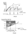
- FIG. 5 shows a change in the injection deviation amount from the injector and the effect of the learning control with respect to the traveling distance.
- the line A1 indicates the deviation amount when the correction of the injection amount of the injector through the learning control is not conducted.
- the line B1 indicates the deviation amount as corrected through the learning control by using the threshold values in step S14A.
- the line B2 indicates the deviation amount as corrected through the learning control by using the threshold values in step S14B.
- the deviation amount is reduced to a level G1 each time the learning control is conducted.
- the deviation amount is reduced to a level G2 (G2 > G1) each time the learning control is conducted.
- the execution condition threshold value is less strict than in the case of the line B1.
- G2 > G1 results in a decreased precision in the correction amount of the learning result.
- the level G2 is also within the permissible range.
- step S14B of line B2 when the threshold values are lowered in step S14B of line B2, it is difficult to make the deviation amount smaller than that compared to line B1 in which the threshold values of step S14A are used. However, as indicated by the graph B2, it is possible to make the deviation amount smaller than in the case of the graph A1.
- the threshold value used for the determination of the execution condition is forcibly lessened.
- the learning control is executed, with the precision of the correction amount of the learning result being somewhat lowered.
- the precision of the correction amount is within the permissible range.
- the second embodiment it is possible to appropriately widen the determination of the learning execution condition to make it possible to increase the learning frequency, without lowering the precision of the correction amount of the learning result. The second embodiment will be described with reference to FIGS. 6 and 7 .
- a horizontal axis indicates an injection pressure of the fuel from the injector.
- a vertical axis indicates a height image of learning control execution condition threshold values such as circulating water temperature and atmospheric pressure.
- learning control execution condition threshold values such as circulating water temperature and atmospheric pressure.
- a borderline L indicates limit a permissible area of the threshold value with respect to the fuel injection pressure. For example, in the case where the fuel injection pressure is a pressure Ph, it is only necessary for the threshold value to be Th or more.
- the fuel injection pressure up to a pressure Pg refers to the range of pressures within which learning control is possible.
- the learning control is executed within the range R1 so that the determination of the learning control execution condition may be appropriate under any pressure within the injection pressure learning capability range.
- the threshold value is not set to Th but rather to Tg. That is, the proper learning control execution permissible range is the range R1 + the range R2.
- the learning control execution condition is determined only in the range R1, and the execution condition threshold value is not set in an optimum manner.
- the threshold values to be used for the determination of the learning control execution condition are optimized with respect to the fuel injection pressure.
- the learning control capability range is enlarged from the range R1 only to the range R1 + the range R2. In this way, the learning frequency can be increased.
- the second embodiment shown in FIG. 7 has steps S22 to S30 which are the same as those of the first embodiment shown in FIG. 4 , and steps S10 to S18 which differ from those of the first embodiment.
- step S10 of FIG. 7 the controller 30 determines whether or not it is the learning timing. When it is the learning timing for the fuel injection amount (YES in step S10), the procedure advances to step S16. When it is not the learning timing (NO in step S10), the processing is completed. As in, for example, the first embodiment, the controller 30 determines that it is the learning timing when the traveling distance from the previous learning timing has attained a predetermined distance.
- step S16 the controller 30 detects the fuel pressure and the procedure advances to step S18.
- the fuel pressure is used by the controller 30 during the execution of the learning control.
- step S18 the controller 30 obtains a threshold value Wn for determination of a circulating water temperature with regards to a fuel pressure detected from a map or the like.
- the obtained threshold value Wn is substituted for a water temperature threshold value Sw.
- a threshold value Pn for determination of an atmospheric pressure with regards to the fuel pressure detected is obtained from a map or the like.
- the obtained threshold value Pn is substituted for an atmospheric pressure threshold value Sp.
- the controller 30 obtains a threshold value An for the determination of an intake air temperature with respect to the fuel pressure detected from a map or the like.
- the obtained threshold value An is substituted for an intake air temperature threshold value Sa.
- the threshold value Fn for the determination of a fuel temperature with regards to the fuel pressure detected is obtained from a map or the like.
- the obtained threshold value Fn is substituted for a fuel temperature threshold value Sf, and the procedure advances to step S22.
- each threshold value corresponding to the borderline shown in FIG. 6 is fixed.
- Step S16 and step S18 correspond to the learning frequency increase step.
- the processing from step S22 onward is the same as that in the first embodiment, so a description thereof will be left out.
- the range where the learning control execution condition is satisfied is only in the range R1 of FIG. 6 .
- the threshold values are changed appropriately with regards to the fuel injection pressure.
- the range where the learning control execution condition is satisfied is enlarged from mere the range R1 to the range R1 + the range R2 of FIG. 6 .
- step S16 and S18 shown in FIG. 7 is executed to set each threshold value corresponding to the borderline L shown in FIG. 6 .
- each threshold value is set so as to be somewhat below the borderline L shown in FIG. 6 so that each threshold of the execution condition determination is lessened.
- the third embodiment provides similar effects as that of the first embodiment and the second embodiment.
- control system for executing the learning method according to the present invention may be applied to the embodiment as shown in FIG. 1 , and may also be applied to various internal combustion engines in which fuel is injected from an injector.
- the threshold values of the circulating water temperature, the atmospheric pressure, the intake air temperature, and the fuel temperature may all be changed.
- a learning method for an internal combustion engine (10) may include steps as follows. Injection for learning is executed from an injector (43A to 43D) during non-injection operation of the engine (10) with a timing. A correction amount for the injector (43A to 43D) is obtained based on an RPM fluctuation amount of the engine (10) due to the injection for learning and on the RPM of the engine (10).
- a controller (30) determines whether or not a learning control execution condition is satisfied with a predetermined condition with the timing. The controller (30) executes the learning control when the learning control execution condition is satisfied with the predetermined condition. The controller (30) obtains an execution frequency of the learning control. The controller (30) forcibly increases the execution frequency of the learning control when the execution frequency obtained in a previous step has not attained a predetermined frequency.
Landscapes
- Engineering & Computer Science (AREA)
- Chemical & Material Sciences (AREA)
- Combustion & Propulsion (AREA)
- Mechanical Engineering (AREA)
- General Engineering & Computer Science (AREA)
- Electrical Control Of Air Or Fuel Supplied To Internal-Combustion Engine (AREA)
- Combined Controls Of Internal Combustion Engines (AREA)
Applications Claiming Priority (1)
| Application Number | Priority Date | Filing Date | Title |
|---|---|---|---|
| JP2012177001A JP5912984B2 (ja) | 2012-08-09 | 2012-08-09 | 内燃機関の燃料噴射量学習方法 |
Publications (1)
| Publication Number | Publication Date |
|---|---|
| EP2696060A1 true EP2696060A1 (fr) | 2014-02-12 |
Family
ID=48139749
Family Applications (1)
| Application Number | Title | Priority Date | Filing Date |
|---|---|---|---|
| EP13163679.7A Withdrawn EP2696060A1 (fr) | 2012-08-09 | 2013-04-15 | Procédé d'apprentissage de la quantité d'injection de carburant pour moteur à combustion interne |
Country Status (2)
| Country | Link |
|---|---|
| EP (1) | EP2696060A1 (fr) |
| JP (1) | JP5912984B2 (fr) |
Cited By (5)
| Publication number | Priority date | Publication date | Assignee | Title |
|---|---|---|---|---|
| FR3035450A1 (fr) * | 2015-04-21 | 2016-10-28 | Continental Automotive France | Procede et dispositif de surveillance des quantites de carburant injectees dans un moteur a combustion interne |
| CN106246379A (zh) * | 2015-06-15 | 2016-12-21 | 现代自动车株式会社 | 用于控制发动机的装置和方法 |
| FR3047044A1 (fr) * | 2016-01-21 | 2017-07-28 | Continental Automotive France | Procede de gestion de la derive d'un injecteur d'un moteur de vehicule automobile |
| FR3055665A1 (fr) * | 2016-09-02 | 2018-03-09 | Peugeot Citroen Automobiles Sa | Procede d’execution d’un recalage d’injecteur de carburant dans un moteur a combustion interne |
| EP3462010A1 (fr) * | 2017-09-29 | 2019-04-03 | PSA Automobiles SA | Procédé d'exécution d'un recalage d'injecteur de carburant dans un moteur à combustion interne |
Families Citing this family (3)
| Publication number | Priority date | Publication date | Assignee | Title |
|---|---|---|---|---|
| JP6392722B2 (ja) * | 2015-09-29 | 2018-09-19 | 株式会社豊田自動織機 | 内燃機関の燃料噴射制御装置及び内燃機関の燃料噴射量学習方法 |
| JP6848524B2 (ja) * | 2017-02-27 | 2021-03-24 | 株式会社豊田自動織機 | エンジンの制御装置 |
| CN111771050B (zh) * | 2018-02-26 | 2022-03-01 | 日立安斯泰莫株式会社 | 燃料喷射控制装置、燃料喷射控制方法 |
Citations (8)
| Publication number | Priority date | Publication date | Assignee | Title |
|---|---|---|---|---|
| EP1340900A2 (fr) * | 2002-03-01 | 2003-09-03 | Denso Corporation | Système de commande d'injection de carburant pour un moteur à combustion interne |
| JP2005036788A (ja) | 2003-06-27 | 2005-02-10 | Denso Corp | ディーゼル機関の噴射量制御装置 |
| US20080004785A1 (en) * | 2006-07-03 | 2008-01-03 | Denso Corporation | Learning method of injection characteristic and fuel injection controller |
| EP1930577A1 (fr) * | 2005-09-02 | 2008-06-11 | Toyota Jidosha Kabushiki Kaisha | Dispositif de commande d'injection de carburant pour moteur diesel |
| JP2009057853A (ja) | 2007-08-30 | 2009-03-19 | Denso Corp | 内燃機関の燃料噴射制御装置及び内燃機関の燃料噴射量学習方法 |
| EP2112358A2 (fr) * | 2008-04-23 | 2009-10-28 | Toyota Jidosha Kabushiki Kaisha | Appareil de contrôle de l'apprentissage de la quantité de carburant à injecter |
| EP2273091A1 (fr) * | 2009-06-22 | 2011-01-12 | Honda Motor Co., Ltd. | Système de contrôle d'injection de carburant pour un moteur à combustion interne et procédé de contrôle correspondant |
| JP2012177001A (ja) | 2011-02-25 | 2012-09-13 | San-Dia Polymer Ltd | 吸収性樹脂粒子組成物、これを含む吸収体及び吸収性物品 |
Family Cites Families (7)
| Publication number | Priority date | Publication date | Assignee | Title |
|---|---|---|---|---|
| JP3966096B2 (ja) * | 2002-06-20 | 2007-08-29 | 株式会社デンソー | 内燃機関用噴射量制御装置 |
| JP2005146947A (ja) * | 2003-11-13 | 2005-06-09 | Denso Corp | 内燃機関の噴射量制御装置 |
| JP4089600B2 (ja) * | 2003-11-21 | 2008-05-28 | 株式会社デンソー | 内燃機関の噴射量制御装置 |
| JP2008163913A (ja) * | 2006-12-29 | 2008-07-17 | Toyota Motor Corp | 内燃機関の噴射量学習方法及び装置 |
| JP4424393B2 (ja) * | 2007-08-31 | 2010-03-03 | 株式会社デンソー | 内燃機関の燃料噴射制御装置 |
| JP2009250051A (ja) * | 2008-04-02 | 2009-10-29 | Denso Corp | 車載内燃機関の燃料噴射制御装置及び燃料噴射制御システム |
| JP2010261334A (ja) * | 2009-04-30 | 2010-11-18 | Denso Corp | 燃料噴射制御装置 |
-
2012
- 2012-08-09 JP JP2012177001A patent/JP5912984B2/ja not_active Expired - Fee Related
-
2013
- 2013-04-15 EP EP13163679.7A patent/EP2696060A1/fr not_active Withdrawn
Patent Citations (8)
| Publication number | Priority date | Publication date | Assignee | Title |
|---|---|---|---|---|
| EP1340900A2 (fr) * | 2002-03-01 | 2003-09-03 | Denso Corporation | Système de commande d'injection de carburant pour un moteur à combustion interne |
| JP2005036788A (ja) | 2003-06-27 | 2005-02-10 | Denso Corp | ディーゼル機関の噴射量制御装置 |
| EP1930577A1 (fr) * | 2005-09-02 | 2008-06-11 | Toyota Jidosha Kabushiki Kaisha | Dispositif de commande d'injection de carburant pour moteur diesel |
| US20080004785A1 (en) * | 2006-07-03 | 2008-01-03 | Denso Corporation | Learning method of injection characteristic and fuel injection controller |
| JP2009057853A (ja) | 2007-08-30 | 2009-03-19 | Denso Corp | 内燃機関の燃料噴射制御装置及び内燃機関の燃料噴射量学習方法 |
| EP2112358A2 (fr) * | 2008-04-23 | 2009-10-28 | Toyota Jidosha Kabushiki Kaisha | Appareil de contrôle de l'apprentissage de la quantité de carburant à injecter |
| EP2273091A1 (fr) * | 2009-06-22 | 2011-01-12 | Honda Motor Co., Ltd. | Système de contrôle d'injection de carburant pour un moteur à combustion interne et procédé de contrôle correspondant |
| JP2012177001A (ja) | 2011-02-25 | 2012-09-13 | San-Dia Polymer Ltd | 吸収性樹脂粒子組成物、これを含む吸収体及び吸収性物品 |
Cited By (7)
| Publication number | Priority date | Publication date | Assignee | Title |
|---|---|---|---|---|
| FR3035450A1 (fr) * | 2015-04-21 | 2016-10-28 | Continental Automotive France | Procede et dispositif de surveillance des quantites de carburant injectees dans un moteur a combustion interne |
| CN106246379A (zh) * | 2015-06-15 | 2016-12-21 | 现代自动车株式会社 | 用于控制发动机的装置和方法 |
| CN106246379B (zh) * | 2015-06-15 | 2020-12-11 | 现代自动车株式会社 | 用于控制发动机的装置和方法 |
| FR3047044A1 (fr) * | 2016-01-21 | 2017-07-28 | Continental Automotive France | Procede de gestion de la derive d'un injecteur d'un moteur de vehicule automobile |
| FR3055665A1 (fr) * | 2016-09-02 | 2018-03-09 | Peugeot Citroen Automobiles Sa | Procede d’execution d’un recalage d’injecteur de carburant dans un moteur a combustion interne |
| EP3462010A1 (fr) * | 2017-09-29 | 2019-04-03 | PSA Automobiles SA | Procédé d'exécution d'un recalage d'injecteur de carburant dans un moteur à combustion interne |
| FR3071881A1 (fr) * | 2017-09-29 | 2019-04-05 | Psa Automobiles Sa | Procede d’execution d’un recalage d’injecteur de carburant dans un moteur a combustion interne |
Also Published As
| Publication number | Publication date |
|---|---|
| JP5912984B2 (ja) | 2016-04-27 |
| JP2014034933A (ja) | 2014-02-24 |
Similar Documents
| Publication | Publication Date | Title |
|---|---|---|
| EP2696060A1 (fr) | Procédé d'apprentissage de la quantité d'injection de carburant pour moteur à combustion interne | |
| JP4596064B2 (ja) | 内燃機関制御装置及び内燃機関制御システム | |
| JP4924668B2 (ja) | 燃料噴射制御装置 | |
| JP2008038857A (ja) | 筒内噴射式内燃機関の制御装置 | |
| US10113499B2 (en) | Fuel injection control device for internal combustion engine | |
| US7881855B2 (en) | Method for metering fuel into combustion chambers of an internal combustion engine | |
| KR20130127516A (ko) | 엔진의 연소 진단 신호 이상시의 파일럿 분사 타이밍 제어 방법 및 장치 | |
| US7493887B2 (en) | Method for detecting preinjection | |
| JP2010127172A (ja) | 筒内圧センサ特性検出装置 | |
| JP2008184915A (ja) | 内燃機関の燃料噴射制御装置 | |
| JP4738304B2 (ja) | 内燃機関の制御装置 | |
| WO2017069088A1 (fr) | Moteur | |
| KR101338466B1 (ko) | 디젤 엔진의 파일럿 연료 분사 보정 방법 및 시스템 | |
| JP2011226363A (ja) | 内燃機関の異常診断装置 | |
| JP2018204444A (ja) | 内燃機関の燃料噴射制御装置 | |
| US6932059B2 (en) | Fuel injection system of internal combustion engine | |
| JP2009002204A (ja) | 噴射量制御装置およびそれを用いた燃料噴射システム | |
| JP4387384B2 (ja) | 内燃機関の制御装置 | |
| JP4551425B2 (ja) | ディーゼル機関の燃料噴射制御装置 | |
| JP4610407B2 (ja) | 内燃機関の燃料噴射装置 | |
| JP2007023796A (ja) | 燃料噴射装置 | |
| JP5648646B2 (ja) | 燃料噴射制御装置 | |
| JP6330616B2 (ja) | 制御装置 | |
| JP2007032557A (ja) | 燃料噴射制御装置 | |
| JP2010038142A (ja) | 内燃機関の噴射量制御装置 |
Legal Events
| Date | Code | Title | Description |
|---|---|---|---|
| 17P | Request for examination filed |
Effective date: 20130415 |
|
| AK | Designated contracting states |
Kind code of ref document: A1 Designated state(s): AL AT BE BG CH CY CZ DE DK EE ES FI FR GB GR HR HU IE IS IT LI LT LU LV MC MK MT NL NO PL PT RO RS SE SI SK SM TR |
|
| AX | Request for extension of the european patent |
Extension state: BA ME |
|
| PUAI | Public reference made under article 153(3) epc to a published international application that has entered the european phase |
Free format text: ORIGINAL CODE: 0009012 |
|
| STAA | Information on the status of an ep patent application or granted ep patent |
Free format text: STATUS: THE APPLICATION IS DEEMED TO BE WITHDRAWN |
|
| 18D | Application deemed to be withdrawn |
Effective date: 20140813 |