EP2695541B1 - Auftragvorrichtung zum Auftragen von Substanzen - Google Patents
Auftragvorrichtung zum Auftragen von Substanzen Download PDFInfo
- Publication number
- EP2695541B1 EP2695541B1 EP13176672.7A EP13176672A EP2695541B1 EP 2695541 B1 EP2695541 B1 EP 2695541B1 EP 13176672 A EP13176672 A EP 13176672A EP 2695541 B1 EP2695541 B1 EP 2695541B1
- Authority
- EP
- European Patent Office
- Prior art keywords
- protective sleeve
- tubular holder
- use position
- application
- application device
- Prior art date
- Legal status (The legal status is an assumption and is not a legal conclusion. Google has not performed a legal analysis and makes no representation as to the accuracy of the status listed.)
- Active
Links
Images

Classifications
-
- A—HUMAN NECESSITIES
- A46—BRUSHWARE
- A46B—BRUSHES
- A46B11/00—Brushes with reservoir or other means for applying substances, e.g. paints, pastes, water
- A46B11/001—Brushes with reservoir or other means for applying substances, e.g. paints, pastes, water with integral reservoirs
-
- A—HUMAN NECESSITIES
- A46—BRUSHWARE
- A46B—BRUSHES
- A46B11/00—Brushes with reservoir or other means for applying substances, e.g. paints, pastes, water
- A46B11/0072—Details
- A46B11/0079—Arrangements for preventing undesired leakage or dispensing
- A46B11/0089—Caps or covers for bristles
-
- A—HUMAN NECESSITIES
- A46—BRUSHWARE
- A46B—BRUSHES
- A46B17/00—Accessories for brushes
- A46B17/04—Protective covers for the bristles
-
- A—HUMAN NECESSITIES
- A46—BRUSHWARE
- A46B—BRUSHES
- A46B2200/00—Brushes characterized by their functions, uses or applications
- A46B2200/20—Brushes for applying products to surfaces in general
Definitions
- the invention relates to an applicator device for applying substances to an object.
- the applicator has a tubular holder and an applicator provided on the tubular holder.
- a sliding protective sleeve is mounted, which can be arranged in a non-use position surrounding the application part and in a use position releasing the application part.
- Such applicators are preferably used for applying liquid or viscous substances, such as oils, fats, paints, varnishes or the like.
- Such protective sleeves make it possible, in the case of short-term interruptions, to wash out the application part, ie the bristles or the brush. At the same time, the protective sleeve provides protection against contamination.
- the invention has for its object to provide an application device for applying substances to an object, which can be produced in a simple manner and allows easy use. This object is achieved by the applicator device according to the features of claim 1. Further advantageous developments and refinements of the invention are specified in the further claims.
- the protective sleeve Due to the design of the protective sleeve with an open-edged recess which adjoins an end face of the protective sleeve, a quick and easy insertion of the applicator element into the protective sleeve and then a simple positioning and fixing of the protective sleeve to the tubular holder is made possible. It is provided that initially the applicator element is introduced via the open-edged recess of the protective sleeve in a simple manner in the interior of the protective sleeve, so that then without damaging the applicator element positioning and fixing the protective sleeve is made possible on the tubular holder.
- an elaborate threading of the application element which preferably consists of a plurality of bristles or hairs that form a brush, is no longer necessary.
- a sliding movement of the protective sleeve takes place so that the tubular holder completely covers the recess of the protective sleeve and is transferred to a non-use position.
- the protective sleeve can be converted into a use position by only an axial displacement movement and a grip portion of the dispensing device engage in the recess.
- Such a protective sleeve thus not only allows easy mounting on the tubular holder, but at the same time easy positioning in a non-use position to protect the applicator element.
- the protective sleeve has a cross section which corresponds to the cross section of the tubular holder.
- a preferred embodiment of the application device provides that the protective sleeve can be placed laterally on the application part.
- the edge-open end can preferably be positioned near the enclosed end of the application element on the tubular holder, so that a secure insertion of the application element is ensured.
- a rotation of the protective sleeve about its longitudinal axis can be made possible at least slightly, so that bristles or hairs of the applicator element that have not yet fully penetrated are still introduced.
- the protective sleeve can be positioned by an axial displacement movement along the longitudinal axis of the tubular holder on it in a simple manner.
- the open-edged recess on the protective sleeve is preferably U-shaped, wherein the opening width of the recess is formed smaller than a diameter of the tubular holder.
- the length of the open-edged recess of the protective sleeve is preferably smaller than the length of the applicator part. This makes it possible that in a non-use position of the protective sleeve to the tubular holder, the U-shaped recess in the region of the tubular holder, whereby a free access to the applicator element in the radial direction is no longer given.
- the tubular holder preferably has, at an end opposite the applicator element, a connection means for fastening to a Dispensing device, which is preferably attachable to a substance storing the container.
- a Dispensing device which is preferably attachable to a substance storing the container.
- Such dispensing devices are preferably manufactured as injection-molded parts and can be screwed or clipped onto the containers, so that after their actuation the substance is dispensed via the container through the dispensing device into the application device in order to apply this substance via the application element.
- the protective sleeve in a use position at least partially surrounds an output device.
- This allows an additional fixation of the protective sleeve in a position of use on the dispensing device are made possible by, for example, a detent or the like is provided on the dispenser, which locks the protective sleeve in the use position.
- a detent or the like is provided on the dispenser, which locks the protective sleeve in the use position.
- this makes it possible that the tubular holder can be made shorter, so that the overall length of the applicator is shortened, whereby the handling is simplified.
- a closure cap is preferably provided captive.
- the closure cap can be fastened to the protective sleeve so that an airtight closure is made possible and at least a brief interruption without washing out of the application element without drying out is provided.
- the protective sleeve preferably has on its outer side a latching element on which the closure flap can be fastened in a non-use position.
- the applicator element is preferably formed as a brush or by wire or bristle tufts. Depending on the media to be applied, an adjustment can be made.
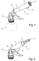
- FIG. 1 is a perspective view of the applicator device 11 according to the invention shown.
- This application device 11 comprises a tubular holder 12 and a protective sleeve 14, which is arranged displaceably on the tubular holder 12.
- the protective sleeve 14 is in the in FIG. 1 arranged embodiment in a non-use position 16 and surrounds a applicator element 17 which is fixed to the tubular holder 12, as is made FIG. 2 evident.
- the application device 11 has, at an end opposite the application element 17, a connection means 19, by means of which the application device 11 can be fastened to an output device 21.
- a plug or screw connection is provided, so that the applicator 11 is arranged replaceable to the output device 21.
- the dispenser 21 itself is attachable to a dispenser or container 23. This is preferably fixed by a screw or clip connection thereto.
- the substance to be applied is stored. These may be spreadable or flowable media to be applied to an article. In particular, these are paints, varnishes, lubricants, pastes or the like.
- About one inside the Dispensing means 21 arranged channel passes the substance from the container 23 in an inner channel of the tubular holder 12 and passes through a central bore in the applicator element 17 to the outside.
- the applicator element 17 is formed by a plurality of bundles of individual bristles, which are arranged in a circle on the tubular holder 12, so that they form a central conveying channel, through which the substance can escape to the front end of the bristle bundles.
- a brush with a central opening may be provided.
- the bristles may be made of wire, artificial or natural material.
- the protective sleeve 14 is slidably mounted on the tubular holder 12, so that these from the non-use position 16 according to FIG. 1 in a use position 25 according to FIG. 2 is displaceable, whereby the applicator element 17 is released.
- the protective sleeve 14 has, at a free end 27 adjacent to an open-edged recess 28 ( FIG. 3 ).
- This open-edged recess 28 is U-shaped and extends in the radial direction only partially over the circumference of the protective sleeve 14.
- In the use position 25 of the protective sleeve 14 grips a handle portion 29 of the dispenser 21 at least partially into the recess 28 of the protective sleeve 14 a.
- additional locking elements may be provided in the region of the grip portion 29 or a connection point between the output device 21 and the connection means 19 of the applicator 11.
- the protective sleeve 14 and the tubular holder 12 preferably have the same cross section, so that on the one hand a sliding movement is made possible, but on the other hand, a slight clamping fixation is also given.
- end of the tubular holder 12 as well as a releasable locking element 33rd be provided to fix the protective sleeve 14 in the non-use position 16.
- FIGS. 3 to 5 By way of example, three assembly steps are shown, which represent a simple mounting of the protective sleeve 14 on the tubular holder 12 for completing the application device 11.
- the protective sleeve 14 is positioned to the tubular holder 12 so that the recess 28 is assigned to the applicator element 17, so that the applicator element 17 passes in a simple manner via the recess 28 into the interior of the protective sleeve 14.
- a lateral placement of the protective sleeve 14 on the applicator element 17 is possible.
- After slipping over the protective sleeve 14 via the applicator element 17 or the free end of the applicator element 17 may preferably be a slight rotation of the protective sleeve 14 about its longitudinal axis to ensure that the applicator element 17 is completely inside the protective sleeve 14.
- a closure cap 31 can be provided on the protective sleeve 14, which can be fastened to the protective sleeve 14 by clamping or latching.
- a retaining tab 32 the flap 31 is connected to the protective sleeve 12 captive.
- a latching element 33 is preferably provided on the protective sleeve 14, whereby the closure flap 31 with the attachment portion 34 engage it and can be held in an open position, as for example from the FIGS. 3 and 4 evident.
Landscapes
- Coating Apparatus (AREA)
Description
- Die Erfindung betrifft eine Auftragvorrichtung zum Auftragen von Substanzen auf einen Gegenstand.
- Aus der
DE 20 2009 003 437 U1 ist eine solche Auftragvorrichtung zum Auftragen von Substanzen auf einen Gegenstand bekannt. Die Auftragvorrichtung weist einen rohrförmigen Halter auf, sowie ein Auftragelement, das an dem rohrförmigen Halter vorgesehen ist. An dem rohrförmigen Halter ist eine verschiebbare Schutzhülse gelagert, die in einer das Auftragteil umgebenden Nichtgebrauchsposition und in einer das Auftragteil freigebenden Gebrauchsposition anordenbar ist. Solche Auftragvorrichtungen werden bevorzugt zum Auftragen von flüssigen oder zähflüssigen Substanzen, wie beispielsweise Öle, Fette, Farben, Lacke oder dergleichen eingesetzt. Solche Schutzhülsen ermöglichen, dass bei kurzfristigen Unterbrechungen ein Auswaschen des Auftragteils, also der Borsten oder des Pinsels, nicht notwendig ist. Gleichzeitig bietet die Schutzhülse einen Schutz gegen Verschmutzung. Allerdings weisen diese Auftragvorrichtungen den Nachteil auf, dass bei der Montage der Schutzhülse, welche über das Auftragteil überzustülpen ist, es oft zu Beschädigungen des Pinsels oder der Borsten durch Umknicken kommt oder dass die Montage zeitaufwändig ist, bis alle einzelnen Borsten innerhalb der Schutzhülse positioniert sind. - Aus der
US 2,633,236 ist eine Verschlusskappe bekannt, welche zum Aufsetzen auf einen Halter eines Pinsels eine U-förmige Ausnehmung aufweist. Nach dem Einführen der Borsten in die Verschlusskappe verrastet diese an dem Halter in einer verdrehsicheren Position, indem Vorsprünge an dem Halter in die U-förmige Ausnehmung der Kappe einrasten. - Aus der
JP H11 208751 A - Aus der
US 6,237,180 B1 geht eine Schutzvorrichtung für Borsten eines Borstenkopfes für eine elektrische Zahnbürste hervor. Diese Schutzvorrichtung weist einen trichterförmigen Bereich zum einfachen Aufsetzen und Einfädeln der Borsten in eine zylindrische Schutzhülse auf. - Der Erfindung liegt die Aufgabe zugrunde, eine Auftragvorrichtung zum Auftragen von Substanzen auf einen Gegenstand vorzuschlagen, welche in einfacher Weise herstellbar ist und einen einfachen Gebrauch ermöglicht. Diese Aufgabe wird durch die Auftragvorrichtung gemäß den Merkmalen des Anspruchs 1 gelöst. Weitere vorteilhafte Weiterbildungen und Ausgestaltungen der Erfindung sind in den weiteren Ansprüchen angegeben.
- Durch die Ausgestaltung der Schutzhülse mit einer randoffenen Ausnehmung, die an eine Stirnseite der Schutzhülse angrenzt, wird ein schnelles und einfaches Einführen des Auftragelementes in die Schutzhülse und anschließend ein einfaches Positionieren und Fixieren der Schutzhülse zum rohrförmigen Halter ermöglicht. Dabei ist vorgesehen, dass zunächst das Auftragelement über die randoffene Ausnehmung der Schutzhülse in einfacher Weise in das Innere der Schutzhülse eingeführt wird, so dass anschließend ohne eine Beschädigung des Auftragelementes eine Positionierung und Fixierung der Schutzhülse auf dem rohrförmigen Halter ermöglicht ist. Ein aufwändiges Einfädeln des Auftragelementes, welches vorzugsweise aus einer Vielzahl von Borsten oder Haaren besteht, die einen Pinsel bilden, ist dabei nicht mehr erforderlich. Darüber hinaus erfolgt unmittelbar nach dem einfachen Aufsetzen der Schutzhülse auf den rohrförmigen Hals eine Schiebebewegung der Schutzhülse, so dass der rohrförmige Halter die Ausnehmung der Schutzhülse vollständig überdeckt und in eine Nichtgebrauchsposition übergeführt ist. Ausgehend von dieser Nichtgebrauchsposition kann durch lediglich eine axiale Verschiebebewegung die Schutzhülse in eine Gebrauchsposition übergeführt werden und ein Griffabschnitt der Ausgabeeinrichtung in die Ausnehmung eingreifen. Eine solche Schutzhülse ermöglicht somit nicht nur eine einfache Montage auf dem rohrförmigen Halter, sondern gleichzeitig ein einfaches Positionieren in einer Nichtgebrauchsposition zum Schutz des Auftragselementes. Darüber hinaus kann durch lediglich eine axiale Verschiebebewegung die Schutzhülse aus der Nichtgebrauchsposition in die Gebrauchsposition übergeführt werden, um eine einfache und schnelle Handhabung der Auftragsvorrichtung zu ermöglichen. Des Weiteren weist die Schutzhülse einen Querschnitt auf, welcher dem Querschnitt des rohrförmigen Halters entspricht. Dadurch ist eine einfache, verschiebbare Anordnung der Schutzhülse zum Halter geschaffen.
- Eine bevorzugte Ausgestaltung der Auftragvorrichtung sieht vor, dass die Schutzhülse seitlich auf das Auftragteil aufsetzbar ist. Dabei kann bevorzugt das randoffene Ende nahe dem eingefassten Ende des Auftragelementes am rohrförmigen Halter positioniert werden, so dass ein sicheres Einführen des Auftragelementes sichergestellt ist. Vorzugsweise kann nach dem seitlichen Aufsetzen der Schutzhülse auf das Auftragelement eine Verdrehung der Schutzhülse um deren Längsachse zumindest geringfügig ermöglicht werden, so dass gegebenenfalls noch nicht vollständig in das Innere gelangte Borsten oder Haare des Auftragelementes noch eingeführt werden. Anschließend kann in einfacher Weise die Schutzhülse durch eine axiale Verschiebebewegung längs der Längsachse des rohrförmigen Halters darauf positioniert werden.
- Die randoffene Ausnehmung an der Schutzhülse ist bevorzugt U-förmig ausgebildet, wobei die Öffnungsbreite der Ausnehmung kleiner als ein Durchmesser des rohrförmigen Halters ausgebildet ist. Dadurch ist auch ein einfaches Einführen des Auftragelements in das Innere der Schutzhülse möglich. Ebenso kann in einfacher Weise ein Aufklipsen der Schutzhülse auf dem rohrförmigen Halter ermöglicht sein.
- Die Länge der randoffenen Ausnehmung der Schutzhülse ist bevorzugt kleiner als die Länge des Auftragteils ausgebildet. Dadurch wird ermöglicht, dass in einer Nichtgebrauchsposition der Schutzhülse zum rohrförmigen Halter die U-förmige Ausnehmung im Bereich des rohrförmigen Halters liegt, wodurch ein freier Zugang zum Auftragelement in radialer Richtung nicht mehr gegeben ist.
- Der rohrförmige Halter weist bevorzugt an einem dem Auftragelement gegenüberliegenden Ende ein Anschlussmittel zum Befestigen an einer Ausgabeeinrichtung auf, die vorzugsweise auf einen die Substanz bevorratenden Behälter anbringbar ist. Solche Ausgabeeinrichtungen sind bevorzugt als Spritzgussteile hergestellt und können auf die Behälter aufschraubbar oder aufklipsbar sein, so dass nach deren Betätigung ein Ausgeben der Substanz über den Behälter durch die Ausgabeeinrichtung hindurch in die Auftragvorrichtung erfolgt, um diese Substanz über das Auftragelement aufzutragen.
- Des Weiteren ist bevorzugt vorgesehen, dass die Schutzhülse in einer Gebrauchsposition zumindest teilweise eine Ausgabeeinrichtung umgibt. Dadurch kann eine zusätzlich Fixierung der Schutzhülse in einer Gebrauchsposition an der Ausgabeeinrichtung ermöglicht werden, indem beispielsweise eine Rastnase oder dergleichen an der Ausgabeeinrichtung vorgesehen ist, welche die Schutzhülse in der Gebrauchsposition arretiert. Darüber hinaus wird dadurch ermöglicht, dass der rohrförmige Halter kürzer ausgebildet werden kann, so dass die Gesamtlänge der Auftragvorrichtung verkürzt ist, wodurch die Handhabung vereinfacht wird.
- An der Schutzhülse ist bevorzugt eine Verschlusskappe unverlierbar vorgesehen. Dadurch kann bei einem Nichtgebrauch die Verschlusskappe an der Schutzhülse befestigt werden, so dass ein luftdichter Abschluss ermöglicht ist und zumindest eine kurze Unterbrechung ohne Auswaschen des Auftragelementes ohne Austrocknen gegeben ist.
- Die Schutzhülse weist bevorzugt an deren Außenseite ein Rastelement auf, an dem die Verschlussklappe in einer Nichtgebrauchsposition befestigbar ist. Somit kann ein ungehindertes Auftragen der Substanz durch die Auftragvorrichtung ermöglicht sein.
- Das Auftragelement ist bevorzugt als Pinsel oder durch Draht- oder Borstenbüschel gebildet. In Abhängigkeit der aufzutragenden Medien kann eine Anpassung erfolgen.
- Die Erfindung sowie weitere vorteilhafte Ausführungsformen und Weiterbildungen derselben werden im Folgenden anhand der in den Zeichnungen dargestellten Beispiele näher beschrieben und erläutert. Die der Beschreibung und den Zeichnungen zu entnehmenden Merkmale können einzeln für sich oder zu mehreren in beliebiger Kombination erfindungsgemäß angewandt werden. Es zeigen:
-
Figur 1 eine perspektivische Ansicht der Auftragvorrichtung in einer Nichtgebrauchsposition an einer Ausgabeeinrichtung, -
Figur 2 die Auftragvorrichtung gemäßFigur 1 in einer Gebrauchsposition, -
Figur 3 eine perspektivische Ansicht eines ersten Montageschritts zum Positionieren einer Schutzhülse an einem rohrförmigen Halter der Auftragvorrichtung, -
Figur 4 eine perspektivische Ansicht eines Zwischenschritts zur Montage der Schutzhülse an dem rohrförmigen Halter und -
Figur 5 eine perspektivische Ansicht einer auf dem rohrförmigen Halter angeordneten Schutzhülse der Auftragvorrichtung. - In
Figur 1 ist eine perspektivische Ansicht der erfindungsgemäßen Auftragvorrichtung 11 dargestellt. Diese Auftragvorrichtung 11 umfasst einen rohrförmigen Halter 12 sowie eine Schutzhülse 14, welche auf dem rohrförmigen Halter 12 verschiebbar angeordnet ist. Die Schutzhülse 14 ist bei der inFigur 1 dargestellten Ausführungsform in einer Nichtgebrauchsposition 16 angeordnet und umgibt ein Auftragelement 17, welches an dem rohrförmigen Halter 12 befestigt ist, wie dies ausFigur 2 hervorgeht. - Die Auftragvorrichtung 11 weist an einem dem Auftragelement 17 gegenüberliegenden Ende ein Anschlussmittel 19 auf, durch welches die Auftragvorrichtung 11 an einer Ausgabeeinrichtung 21 befestigbar ist. Bevorzugt ist eine Steck- oder Schraubverbindung vorgesehen, so dass die Auftragvorrichtung 11 auswechselbar zur Ausgabeeinrichtung 21 angeordnet ist. Die Ausgabeeinrichtung 21 selbst ist an einem Spender oder Behälter 23 befestigbar. Bevorzugt wird dieser durch eine Schraubverbindung oder Klipsverbindung daran fixiert.
- In dem Behälter 23 ist die aufzutragende Substanz bevorratet. Hierbei kann es sich um streich- oder fließfähige Medien handeln, die auf einen Gegenstand aufzutragen sind. Insbesondere handelt es sich um Farben, Lacke, Schmierstoffe, Pasten oder dergleichen. Über einen im Inneren der Ausgabeeinrichtung 21 angeordneten Kanal gelangt die Substanz aus dem Behälter 23 in einen innenliegenden Kanal des rohrförmigen Halters 12 und gelangt durch eine mittlere Bohrung im Auftragelement 17 nach außen. Bevorzugt ist das Auftragelement 17 durch mehrere Bündel von einzelnen Borsten ausgebildet, die kreisförmig am rohrförmigen Halter 12 angeordnet sind, so dass diese einen mittleren Förderkanal bilden, durch welches die Substanz bis zum vorderen Ende der Borstenbündel austreten kann. Alternativ kann auch ein Pinsel mit einer mittleren Öffnung vorgesehen sein. Die Borsten können aus Draht, aus künstlichem oder aus natürlichem Material bestehen.
- Die Schutzhülse 14 ist auf dem rohrförmigen Halter 12 verschiebbar gelagert, so dass diese aus der Nichtgebrauchsposition 16 gemäß
Figur 1 in eine Gebrauchsposition 25 gemäßFigur 2 verschiebbar ist, wodurch das Auftragselement 17 freigegeben wird. - Die Schutzhülse 14 weist an einem freien Ende 27 angrenzend eine randoffene Ausnehmung 28 auf (
Figur 3 ). Diese randoffene Ausnehmung 28 ist U-förmig ausgebildet und erstreckt sich in radialer Richtung nur teilweise über den Umfang der Schutzhülse 14. In der Gebrauchsposition 25 der Schutzhülse 14 (Figur 2 ) greift ein Griffabschnitt 29 der Ausgabeeinrichtung 21 zumindest teilweise in die Ausnehmung 28 der Schutzhülse 14 ein. Dadurch kann eine verrastende Fixierung der Schutzhülse 14 in der Gebrauchsposition 25 ermöglicht sein. Ebenso können zusätzlich Rastelemente im Bereich des Griffabschnitts 29 oder einer Anschlussstelle zwischen der Ausgabeeinrichtung 21 und dem Anschlussmittel 19 der Auftragvorrichtung 11 vorgesehen sein. - Zum Überführen der Schutzhülse 14 aus der Gebrauchsposition 25 gemäß
Figur 2 in eine Nichtgebrauchsposition 16 gemäßFigur 1 ist lediglich eine axiale Verschiebebewegung erforderlich. Die Schutzhülse 14 und der rohrförmige Halter 12 weisen vorzugsweise denselben Querschnitt auf, so dass einerseits eine Verschiebebewegung ermöglicht ist, jedoch andererseits eine leichte klemmende Fixierung ebenso gegeben ist. Zusätzlich kann an dem zum Auftragelement 17 weisenden Ende des rohrförmigen Halters 12 ebenso ein lösbares Rastelement 33 vorgesehen sein, um die Schutzhülse 14 in der Nichtgebrauchsposition 16 zu fixieren. - In den
Figuren 3 bis 5 sind beispielhaft drei Montageschritte dargestellt, welche eine einfache Montage der Schutzhülse 14 auf dem rohrförmigen Halter 12 zur Komplettierung der Auftragvorrichtung 11 darstellen. - Zunächst wird gemäß
Figur 3 die Schutzhülse 14 derart zum rohrförmigen Halter 12 positioniert, dass die Ausnehmung 28 dem Auftragelement 17 zugeordnet ist, so dass das Auftragelement 17 in einfacher Weise über die Ausnehmung 28 in das Innere der Schutzhülse 14 gelangt. Hierfür ist ein seitliches Aufsetzen der Schutzhülse 14 auf das Auftragelement 17 möglich. Nach dem Überstülpen der Schutzhülse 14 über das Auftragelement 17 bzw. das freie Ende des Auftragelementes 17 kann bevorzugt eine geringfügige Verdrehung der Schutzhülse 14 um deren Längsachse erfolgen, um Sicherzustellen, dass das Auftragelement 17 vollständig im Inneren der Schutzhülse 14 liegt. Anschließend wird das freie Ende 27 des rohrförmigen Halters 12 in Richtung auf den rohrförmigen Halter 12 zu bewegt, wie dies inFigur 2 dargestellt ist. Durch weiteres Aufschieben der Schutzhülse 14 auf den rohrförmigen Halter 12 wird diese in eine Nichtgebrauchsposition 16 übergeführt, so dass der rohrförmige Halter 12 die Ausnehmung 28 die Schutzhülse 14 vollständig überdeckt. Dies ist inFigur 5 dargestellt. - An der Schutzhülse 14 kann des Weiteren eine Verschlusskappe 31 vorgesehen sein, welche durch Klemmung oder Verrastung an der Schutzhülse 14 befestigbar ist. Über eine Haltelasche 32 ist die Verschlussklappe 31 mit der Schutzhülse 12 unverlierbar verbunden. Ergänzend ist bevorzugt an der Schutzhülse 14 ein Rastelement 33 vorgesehen, wodurch die Verschlussklappe 31 mit dessen Befestigungsabschnitt 34 daran angreifen und in einer Öffnungsposition gehalten werden kann, wie dies beispielsweise aus den
Figuren 3 und 4 hervorgeht.
Claims (8)
- Auftragvorrichtung zum Auftragen von Substanzen auf einen Gegenstand, mit einem rohrförmigen Halter (12), mit einem Auftragelement (17), das an dem rohrförmigen Halter (12) vorgesehen ist, mit einer verschiebbar am rohrförmigen Halter (12) gelagerten Schutzhülse (14), die in einer das Auftragelement (17) umgebenden Nichtgebrauchsposition (16) und in einer das Auftragelement (17) freigebenden Gebrauchsposition (25) anordenbar ist, dadurch gekennzeichnet, dass an einem stirnseitigen Ende (27) der Schutzhülse (14) angrenzend eine randoffene Ausnehmung (28) vorgesehen ist, so dass zum Positionieren der Schutzhülse (14) auf dem rohrförmigen Halter (12) zunächst das Auftragelement (17) in die Schutzhülse (12) zumindest über die randoffene Ausnehmung (28) eingeführt wird und anschließend die Schutzhülse (14) auf dem rohrförmigen Halter (12) in axialer Richtung aufgesteckt ist und durch weiteres Aufschieben der Schutzhülse (14) auf den rohrförmigen Halter (12) in eine Nichtgebrauchsposition (16) übergeführt ist, dass der rohrförmige Halter (12) die Ausnehmung (28) der Schutzhülse (14) in der Nichtgebrauchsposition (16) vollständig überdeckt und lediglich durch eine axiale Verschiebebewegung in die Gebrauchsposition (25) überführbar ist und in der Gebrauchsposition ein Griffabschnitt (29) der Ausgabeeinrichtung (21) in die Ausnehmung (28) eingreift und dass die Schutzhülse (14) einen Querschnitt aufweist, welcher dem Querschnitt des rohrförmigen Halters (12) entspricht.
- Auftragvorrichtung nach Anspruch 1, dadurch gekennzeichnet, dass die Schutzhülse (14) seitlich auf das Auftragelement (17) aufsetzbar ist.
- Auftragvorrichtung nach einem der vorhergehenden Ansprüche, dadurch gekennzeichnet, dass die randoffene Ausnehmung (28) U-förmig ausgebildet ist und die Öffnungsbreite der Ausnehmung (28) kleiner als ein Durchmesser des rohrförmigen Halters (12) ausgebildet ist.
- Auftragvorrichtung nach einem der vorhergehenden Ansprüche, dadurch gekennzeichnet, dass die Länge der randoffenen Ausnehmung (28) kleiner als die Länge des Auftragelementes (17) ausgebildet ist.
- Auftragvorrichtung nach einem der vorhergehenden Ansprüche, dadurch gekennzeichnet, dass der rohrförmige Halter (12) an einem dem Auftragelement (17) gegenüberliegenden Ende einen Anschluss zum Befestigen an einer Ausgabeeinrichtung (21) aufweist, die vorzugsweise auf einen die Substanz bevorratenden Behälter (23) anbringbar ist.
- Auftragvorrichtung nach einem der vorhergehenden Ansprüche, dadurch gekennzeichnet, dass an der Schutzhülse (14) eine Verschlusskappe (31) unverlierbar angeordnet ist.
- Auftragvorrichtung nach einem der vorhergehenden Ansprüche, dadurch gekennzeichnet, dass an einer Außenseite der Schutzhülse (14) ein Rastelement (33) angeordnet ist und die Verschlusskappe (31) in einer Nichtgebrauchsposition (16) daran befestigbar ist.
- Auftragvorrichtung nach einem der vorhergehenden Ansprüche, dadurch gekennzeichnet, dass das Auftragelement (17) als Pinsel oder als Draht- oder Borstenbündel ausgebildet ist.
Applications Claiming Priority (1)
| Application Number | Priority Date | Filing Date | Title |
|---|---|---|---|
| DE202012103015U DE202012103015U1 (de) | 2012-08-10 | 2012-08-10 | Auftragvorrichtung zum Auftragen von Substanzen |
Publications (2)
| Publication Number | Publication Date |
|---|---|
| EP2695541A1 EP2695541A1 (de) | 2014-02-12 |
| EP2695541B1 true EP2695541B1 (de) | 2017-12-20 |
Family
ID=48875522
Family Applications (1)
| Application Number | Title | Priority Date | Filing Date |
|---|---|---|---|
| EP13176672.7A Active EP2695541B1 (de) | 2012-08-10 | 2013-07-16 | Auftragvorrichtung zum Auftragen von Substanzen |
Country Status (2)
| Country | Link |
|---|---|
| EP (1) | EP2695541B1 (de) |
| DE (1) | DE202012103015U1 (de) |
Family Cites Families (4)
| Publication number | Priority date | Publication date | Assignee | Title |
|---|---|---|---|---|
| US2633236A (en) * | 1949-05-31 | 1953-03-31 | Marsh Stencil Machine Company | Cover |
| JP3770439B2 (ja) * | 1998-01-29 | 2006-04-26 | 株式会社吉野工業所 | エアゾール式液体噴出容器 |
| US6237180B1 (en) * | 1999-07-01 | 2001-05-29 | Virginia Serafina Viego | Device for extending the effectiveness and life of electric toothbrush heads |
| DE202009003437U1 (de) * | 2009-03-11 | 2009-05-28 | Tunap Industrie Chemie Gmbh & Co. Produktions Kg | Werkzeug zum Auftragen einer Substanz |
-
2012
- 2012-08-10 DE DE202012103015U patent/DE202012103015U1/de not_active Expired - Lifetime
-
2013
- 2013-07-16 EP EP13176672.7A patent/EP2695541B1/de active Active
Non-Patent Citations (1)
| Title |
|---|
| None * |
Also Published As
| Publication number | Publication date |
|---|---|
| DE202012103015U1 (de) | 2013-11-12 |
| EP2695541A1 (de) | 2014-02-12 |
Similar Documents
| Publication | Publication Date | Title |
|---|---|---|
| DE10029378B4 (de) | Applikationseinrichtung für Kosmetikflüssigkeiten, insbesondere Mascara-Test-Applikator | |
| DE69907335T2 (de) | Vorrichtung zum Auftragen von Schminkprodukten mit einer Bürste, Verfahren zu dessen Herstellung und Auftragseinheit mit einer solchen Vorrichtung | |
| EP1752063B1 (de) | Applikator, insbesondere für Mascara oder ähnliche Kosmetika | |
| DE2250576A1 (de) | Auftrager mit pinsel | |
| DE69704107T2 (de) | Applikator-Haltervorrichtung | |
| DE3020838C2 (de) | ||
| DE3738678A1 (de) | Fluessigkeitsapplikator, beispielsweise kosmetikinstrument, schreibgeraet und dergl. | |
| DE2204166A1 (de) | Kosmetikgeraet | |
| DE102008008267B4 (de) | Schutzkappe, Montageanordnung und Verfahren für die Montage von Leitungen im Rohbau eines Kraftfahrzeugs | |
| EP2079340A1 (de) | Applikator | |
| WO1995020891A1 (de) | Applikations-system | |
| EP3855975A1 (de) | Kosmetikpinsel und kosmetikpinselvorrichtung | |
| EP2557644B1 (de) | Einführhilfe für Kabel | |
| EP2833497B1 (de) | Befestigungselement | |
| EP2695541A1 (de) | Auftragvorrichtung zum Auftragen von Substanzen | |
| EP2806506B1 (de) | Abdeckhaube zur Anordnung an einem mehrpoligen Steckerelement | |
| DE3507133A1 (de) | Aerosolspender | |
| EP2443704B1 (de) | Vorrichtung zum aufziehen und positionieren einer tülle auf ein kabel | |
| WO2009065562A2 (de) | Bürste zum übertrag von flüssigen oder pastösen medien | |
| EP2481606B1 (de) | Auftragsgerät | |
| EP2227983B1 (de) | Werkzeug zum Auftragen einer Substanz | |
| EP0185284A2 (de) | Haarbürste | |
| DE19851219A1 (de) | Kosmetikstift | |
| DE202009012010U1 (de) | Interdentalbürste | |
| EP4229721A1 (de) | Schutzkappe |
Legal Events
| Date | Code | Title | Description |
|---|---|---|---|
| AK | Designated contracting states |
Kind code of ref document: A1 Designated state(s): AL AT BE BG CH CY CZ DE DK EE ES FI FR GB GR HR HU IE IS IT LI LT LU LV MC MK MT NL NO PL PT RO RS SE SI SK SM TR |
|
| AX | Request for extension of the european patent |
Extension state: BA ME |
|
| PUAI | Public reference made under article 153(3) epc to a published international application that has entered the european phase |
Free format text: ORIGINAL CODE: 0009012 |
|
| 17P | Request for examination filed |
Effective date: 20140812 |
|
| RBV | Designated contracting states (corrected) |
Designated state(s): AL AT BE BG CH CY CZ DE DK EE ES FI FR GB GR HR HU IE IS IT LI LT LU LV MC MK MT NL NO PL PT RO RS SE SI SK SM TR |
|
| 17Q | First examination report despatched |
Effective date: 20141028 |
|
| GRAP | Despatch of communication of intention to grant a patent |
Free format text: ORIGINAL CODE: EPIDOSNIGR1 |
|
| STAA | Information on the status of an ep patent application or granted ep patent |
Free format text: STATUS: GRANT OF PATENT IS INTENDED |
|
| INTG | Intention to grant announced |
Effective date: 20170712 |
|
| GRAS | Grant fee paid |
Free format text: ORIGINAL CODE: EPIDOSNIGR3 |
|
| GRAA | (expected) grant |
Free format text: ORIGINAL CODE: 0009210 |
|
| STAA | Information on the status of an ep patent application or granted ep patent |
Free format text: STATUS: THE PATENT HAS BEEN GRANTED |
|
| AK | Designated contracting states |
Kind code of ref document: B1 Designated state(s): AL AT BE BG CH CY CZ DE DK EE ES FI FR GB GR HR HU IE IS IT LI LT LU LV MC MK MT NL NO PL PT RO RS SE SI SK SM TR |
|
| REG | Reference to a national code |
Ref country code: GB Ref legal event code: FG4D Free format text: NOT ENGLISH |
|
| REG | Reference to a national code |
Ref country code: CH Ref legal event code: EP |
|
| REG | Reference to a national code |
Ref country code: IE Ref legal event code: FG4D Free format text: LANGUAGE OF EP DOCUMENT: GERMAN |
|
| REG | Reference to a national code |
Ref country code: AT Ref legal event code: REF Ref document number: 955575 Country of ref document: AT Kind code of ref document: T Effective date: 20180115 |
|
| REG | Reference to a national code |
Ref country code: DE Ref legal event code: R096 Ref document number: 502013009047 Country of ref document: DE |
|
| REG | Reference to a national code |
Ref country code: NL Ref legal event code: MP Effective date: 20171220 |
|
| PG25 | Lapsed in a contracting state [announced via postgrant information from national office to epo] |
Ref country code: LT Free format text: LAPSE BECAUSE OF FAILURE TO SUBMIT A TRANSLATION OF THE DESCRIPTION OR TO PAY THE FEE WITHIN THE PRESCRIBED TIME-LIMIT Effective date: 20171220 Ref country code: SE Free format text: LAPSE BECAUSE OF FAILURE TO SUBMIT A TRANSLATION OF THE DESCRIPTION OR TO PAY THE FEE WITHIN THE PRESCRIBED TIME-LIMIT Effective date: 20171220 Ref country code: NO Free format text: LAPSE BECAUSE OF FAILURE TO SUBMIT A TRANSLATION OF THE DESCRIPTION OR TO PAY THE FEE WITHIN THE PRESCRIBED TIME-LIMIT Effective date: 20180320 Ref country code: FI Free format text: LAPSE BECAUSE OF FAILURE TO SUBMIT A TRANSLATION OF THE DESCRIPTION OR TO PAY THE FEE WITHIN THE PRESCRIBED TIME-LIMIT Effective date: 20171220 |
|
| REG | Reference to a national code |
Ref country code: LT Ref legal event code: MG4D |
|
| PG25 | Lapsed in a contracting state [announced via postgrant information from national office to epo] |
Ref country code: BG Free format text: LAPSE BECAUSE OF FAILURE TO SUBMIT A TRANSLATION OF THE DESCRIPTION OR TO PAY THE FEE WITHIN THE PRESCRIBED TIME-LIMIT Effective date: 20180320 Ref country code: GR Free format text: LAPSE BECAUSE OF FAILURE TO SUBMIT A TRANSLATION OF THE DESCRIPTION OR TO PAY THE FEE WITHIN THE PRESCRIBED TIME-LIMIT Effective date: 20180321 Ref country code: RS Free format text: LAPSE BECAUSE OF FAILURE TO SUBMIT A TRANSLATION OF THE DESCRIPTION OR TO PAY THE FEE WITHIN THE PRESCRIBED TIME-LIMIT Effective date: 20171220 Ref country code: HR Free format text: LAPSE BECAUSE OF FAILURE TO SUBMIT A TRANSLATION OF THE DESCRIPTION OR TO PAY THE FEE WITHIN THE PRESCRIBED TIME-LIMIT Effective date: 20171220 Ref country code: LV Free format text: LAPSE BECAUSE OF FAILURE TO SUBMIT A TRANSLATION OF THE DESCRIPTION OR TO PAY THE FEE WITHIN THE PRESCRIBED TIME-LIMIT Effective date: 20171220 |
|
| REG | Reference to a national code |
Ref country code: FR Ref legal event code: PLFP Year of fee payment: 6 |
|
| PG25 | Lapsed in a contracting state [announced via postgrant information from national office to epo] |
Ref country code: NL Free format text: LAPSE BECAUSE OF FAILURE TO SUBMIT A TRANSLATION OF THE DESCRIPTION OR TO PAY THE FEE WITHIN THE PRESCRIBED TIME-LIMIT Effective date: 20171220 |
|
| PG25 | Lapsed in a contracting state [announced via postgrant information from national office to epo] |
Ref country code: CY Free format text: LAPSE BECAUSE OF FAILURE TO SUBMIT A TRANSLATION OF THE DESCRIPTION OR TO PAY THE FEE WITHIN THE PRESCRIBED TIME-LIMIT Effective date: 20171220 Ref country code: EE Free format text: LAPSE BECAUSE OF FAILURE TO SUBMIT A TRANSLATION OF THE DESCRIPTION OR TO PAY THE FEE WITHIN THE PRESCRIBED TIME-LIMIT Effective date: 20171220 Ref country code: SK Free format text: LAPSE BECAUSE OF FAILURE TO SUBMIT A TRANSLATION OF THE DESCRIPTION OR TO PAY THE FEE WITHIN THE PRESCRIBED TIME-LIMIT Effective date: 20171220 Ref country code: CZ Free format text: LAPSE BECAUSE OF FAILURE TO SUBMIT A TRANSLATION OF THE DESCRIPTION OR TO PAY THE FEE WITHIN THE PRESCRIBED TIME-LIMIT Effective date: 20171220 Ref country code: ES Free format text: LAPSE BECAUSE OF FAILURE TO SUBMIT A TRANSLATION OF THE DESCRIPTION OR TO PAY THE FEE WITHIN THE PRESCRIBED TIME-LIMIT Effective date: 20171220 |
|
| PG25 | Lapsed in a contracting state [announced via postgrant information from national office to epo] |
Ref country code: PL Free format text: LAPSE BECAUSE OF FAILURE TO SUBMIT A TRANSLATION OF THE DESCRIPTION OR TO PAY THE FEE WITHIN THE PRESCRIBED TIME-LIMIT Effective date: 20171220 Ref country code: RO Free format text: LAPSE BECAUSE OF FAILURE TO SUBMIT A TRANSLATION OF THE DESCRIPTION OR TO PAY THE FEE WITHIN THE PRESCRIBED TIME-LIMIT Effective date: 20171220 Ref country code: IT Free format text: LAPSE BECAUSE OF FAILURE TO SUBMIT A TRANSLATION OF THE DESCRIPTION OR TO PAY THE FEE WITHIN THE PRESCRIBED TIME-LIMIT Effective date: 20171220 Ref country code: SM Free format text: LAPSE BECAUSE OF FAILURE TO SUBMIT A TRANSLATION OF THE DESCRIPTION OR TO PAY THE FEE WITHIN THE PRESCRIBED TIME-LIMIT Effective date: 20171220 Ref country code: IS Free format text: LAPSE BECAUSE OF FAILURE TO SUBMIT A TRANSLATION OF THE DESCRIPTION OR TO PAY THE FEE WITHIN THE PRESCRIBED TIME-LIMIT Effective date: 20180420 |
|
| REG | Reference to a national code |
Ref country code: DE Ref legal event code: R097 Ref document number: 502013009047 Country of ref document: DE |
|
| PG25 | Lapsed in a contracting state [announced via postgrant information from national office to epo] |
Ref country code: MT Free format text: LAPSE BECAUSE OF FAILURE TO SUBMIT A TRANSLATION OF THE DESCRIPTION OR TO PAY THE FEE WITHIN THE PRESCRIBED TIME-LIMIT Effective date: 20171220 |
|
| PLBE | No opposition filed within time limit |
Free format text: ORIGINAL CODE: 0009261 |
|
| STAA | Information on the status of an ep patent application or granted ep patent |
Free format text: STATUS: NO OPPOSITION FILED WITHIN TIME LIMIT |
|
| 26N | No opposition filed |
Effective date: 20180921 |
|
| PG25 | Lapsed in a contracting state [announced via postgrant information from national office to epo] |
Ref country code: DK Free format text: LAPSE BECAUSE OF FAILURE TO SUBMIT A TRANSLATION OF THE DESCRIPTION OR TO PAY THE FEE WITHIN THE PRESCRIBED TIME-LIMIT Effective date: 20171220 |
|
| PG25 | Lapsed in a contracting state [announced via postgrant information from national office to epo] |
Ref country code: SI Free format text: LAPSE BECAUSE OF FAILURE TO SUBMIT A TRANSLATION OF THE DESCRIPTION OR TO PAY THE FEE WITHIN THE PRESCRIBED TIME-LIMIT Effective date: 20171220 |
|
| REG | Reference to a national code |
Ref country code: CH Ref legal event code: PL |
|
| PG25 | Lapsed in a contracting state [announced via postgrant information from national office to epo] |
Ref country code: MC Free format text: LAPSE BECAUSE OF FAILURE TO SUBMIT A TRANSLATION OF THE DESCRIPTION OR TO PAY THE FEE WITHIN THE PRESCRIBED TIME-LIMIT Effective date: 20171220 Ref country code: LU Free format text: LAPSE BECAUSE OF NON-PAYMENT OF DUE FEES Effective date: 20180716 |
|
| REG | Reference to a national code |
Ref country code: IE Ref legal event code: MM4A |
|
| PG25 | Lapsed in a contracting state [announced via postgrant information from national office to epo] |
Ref country code: IE Free format text: LAPSE BECAUSE OF NON-PAYMENT OF DUE FEES Effective date: 20180716 Ref country code: CH Free format text: LAPSE BECAUSE OF NON-PAYMENT OF DUE FEES Effective date: 20180731 Ref country code: LI Free format text: LAPSE BECAUSE OF NON-PAYMENT OF DUE FEES Effective date: 20180731 |
|
| REG | Reference to a national code |
Ref country code: AT Ref legal event code: MM01 Ref document number: 955575 Country of ref document: AT Kind code of ref document: T Effective date: 20180716 |
|
| PG25 | Lapsed in a contracting state [announced via postgrant information from national office to epo] |
Ref country code: AT Free format text: LAPSE BECAUSE OF NON-PAYMENT OF DUE FEES Effective date: 20180716 |
|
| PG25 | Lapsed in a contracting state [announced via postgrant information from national office to epo] |
Ref country code: TR Free format text: LAPSE BECAUSE OF FAILURE TO SUBMIT A TRANSLATION OF THE DESCRIPTION OR TO PAY THE FEE WITHIN THE PRESCRIBED TIME-LIMIT Effective date: 20171220 |
|
| PG25 | Lapsed in a contracting state [announced via postgrant information from national office to epo] |
Ref country code: HU Free format text: LAPSE BECAUSE OF FAILURE TO SUBMIT A TRANSLATION OF THE DESCRIPTION OR TO PAY THE FEE WITHIN THE PRESCRIBED TIME-LIMIT; INVALID AB INITIO Effective date: 20130716 Ref country code: PT Free format text: LAPSE BECAUSE OF FAILURE TO SUBMIT A TRANSLATION OF THE DESCRIPTION OR TO PAY THE FEE WITHIN THE PRESCRIBED TIME-LIMIT Effective date: 20171220 |
|
| PG25 | Lapsed in a contracting state [announced via postgrant information from national office to epo] |
Ref country code: MK Free format text: LAPSE BECAUSE OF NON-PAYMENT OF DUE FEES Effective date: 20171220 |
|
| PG25 | Lapsed in a contracting state [announced via postgrant information from national office to epo] |
Ref country code: AL Free format text: LAPSE BECAUSE OF FAILURE TO SUBMIT A TRANSLATION OF THE DESCRIPTION OR TO PAY THE FEE WITHIN THE PRESCRIBED TIME-LIMIT Effective date: 20171220 |
|
| P01 | Opt-out of the competence of the unified patent court (upc) registered |
Effective date: 20230515 |
|
| PGFP | Annual fee paid to national office [announced via postgrant information from national office to epo] |
Ref country code: GB Payment date: 20250522 Year of fee payment: 13 |
|
| PGFP | Annual fee paid to national office [announced via postgrant information from national office to epo] |
Ref country code: BE Payment date: 20250619 Year of fee payment: 13 |
|
| PGFP | Annual fee paid to national office [announced via postgrant information from national office to epo] |
Ref country code: FR Payment date: 20250508 Year of fee payment: 13 |
|
| PGFP | Annual fee paid to national office [announced via postgrant information from national office to epo] |
Ref country code: DE Payment date: 20250724 Year of fee payment: 13 |