EP2691807B1 - Eyewear washing machine and method - Google Patents
Eyewear washing machine and method Download PDFInfo
- Publication number
- EP2691807B1 EP2691807B1 EP12714470.7A EP12714470A EP2691807B1 EP 2691807 B1 EP2691807 B1 EP 2691807B1 EP 12714470 A EP12714470 A EP 12714470A EP 2691807 B1 EP2691807 B1 EP 2691807B1
- Authority
- EP
- European Patent Office
- Prior art keywords
- eyewear
- support bracket
- wash fluid
- wash
- cleaning device
- Prior art date
- Legal status (The legal status is an assumption and is not a legal conclusion. Google has not performed a legal analysis and makes no representation as to the accuracy of the status listed.)
- Active
Links
Images


Classifications
-
- G—PHYSICS
- G02—OPTICS
- G02C—SPECTACLES; SUNGLASSES OR GOGGLES INSOFAR AS THEY HAVE THE SAME FEATURES AS SPECTACLES; CONTACT LENSES
- G02C13/00—Assembling; Repairing; Cleaning
- G02C13/006—Devices specially adapted for cleaning spectacles frame or lenses
-
- B—PERFORMING OPERATIONS; TRANSPORTING
- B08—CLEANING
- B08B—CLEANING IN GENERAL; PREVENTION OF FOULING IN GENERAL
- B08B3/00—Cleaning by methods involving the use or presence of liquid or steam
- B08B3/02—Cleaning by the force of jets or sprays
- B08B3/022—Cleaning travelling work
Definitions
- the invention relates to devices and methods for cleaning eyewear.
- Lenses and frames of eyewear gather dust, fingerprints, sweat, and other foreign substances through daily wearing activities.
- Known eyeglass cleaning devices are described in U.S. Patent No. 5,143,101 issued to Avi Mor on September 1, 1992 , U.S. Patent No. 6,338,350 issued to Paul Ewen on January 15, 2002 , and U.S. Patent No. 7,412,980 issued to Jean Gehrig et al. on August 19, 2008 .
- U.S. Patent No. 5,143,101 discloses a compact portable lens washing apparatus including a wash chamber, a reservoir for holding wash fluid, a pair of spaced nozzles facing each other, a lens support for holding a lens between the nozzles, a pump for squirting wash fluid through the nozzles onto the lens, a heater for heating the wash fluid, mechanism for maintaining a wash fluid vapor atmosphere in the wash chamber after the pump shuts off, and electronic elements for controlling the operation of the apparatus.
- Also disclosed is a method for washing a lens that includes the steps of impinging the lens surfaces with an organic volatile wash fluid during a wash cycle, shutting of the flow of wash fluid, allowing residual wash fluid to be drawn of the lens edge by fibers or filaments, and drying the lens in the presence of a wash fluid vapor atmosphere.
- U.S. Patent No. 6,338,350 discloses a portable device for cleaning eyeglasses.
- a transparent enclosure is provided having an upper chamber for cleaning the eyeglasses, a lower left chamber which may be removable for containing the cleaning solution and a lower right chamber housing a pump which is powered by batteries and controlled by a microprocessor.
- the pump circulates cleaning solution through a plurality of apertures in the floor of the upper chamber which creates a spray on the eyeglasses.
- a fan with a heating coil then circulates warm air over the eyeglasses in order to dry them.
- U.S. Patent No. 7,412,980 discloses a washing machine for glass lenses or other similar items of the type including a conveyor which has a bearing surface for moving the lenses through a washing chamber made of a succession of washing means.
- the traction force transmitted by the aforementioned bearing surface is carried out by two chains with endless links, located on the both sides of the aforementioned bearing surface, each chain being joined at the longitudinal side corresponding to the aforementioned bearing surface and is stretched tight between two driving gears, of axis parallel to the plane of the aforementioned bearing surface and perpendicular to the direction of displacement.
- JP 2005 173452 discloses an automatic spectacles cleaning section equipped with means which hold left and right temples of the spectacles in a folded state and rotationally hold the spectacles with respect to at least two or more cleaning liquid jetting means.
- the manual effort of wiping lenses with a clean cloth is often unavailable or ineffective and can especially damage the lenses of the eyewear when foreign substances, such as sand grains, are wiped across them.
- the exemplary embodiments of the present invention have a dual purpose of utility and entertainment.
- embodiments permit a user to direct cleaning solution to user-selected portions of the glasses so that cleaning solution can be focused on the portions of the lenses and/or frames that requiring washing.
- exemplary embodiments of the invention provide an eyewear washing machine utilizing nozzles that will direct a wash fluid, under pressure, onto the front and back of the lenses and onto the frames of the eyewear for a preset time period.
- the eyewear will be secured in place by the user to a support bracket near the center of the machine.
- the orientation of the support bracket may be user-controlled.
- the washing cycle will be followed by a drying cycle that will direct a stream of air onto the eyewear utilizing piping and a diffuser connected to a blower.
- embodiments permit manual cleaning option in a game-like, entertaining format. Additional advantages and novel aspects of embodiments of the invention will be apparent from the following disclosure. Exemplary embodiments of the invention provide for entertaining a user by enabling the user to manually direct the wash fluid onto the lenses or frames of the eyewear by using a trackball to rotate the support bracket and the attached eyewear during the washing cycle.
- known glasses cleaning devices do not allow for a manual cleaning option in a game-like, entertaining format, as hereinafter described, or allow the user to focus the wash fluid on the eyewear at the point where there is greatest need. Further, known devices are limited in that they are designed for personal, rather than public, use. None of these known devices are available in a public readily accessible format and provide for the ability to clean the lenses as well as the frames of the eyewear in a focused manner.
- the invention provides an eyewear cleaning device according to claim 1 and a method for operating an eyewear cleaning device according to claim 14.
- Exemplary embodiments of the invention provide a display cabinet that houses a transparent cylindrical wash chamber, the nozzles used for spraying the wash fluid on the lenses and frames of the eyewear during the washing cycle, a portion of the tubing used to transport the wash fluid from a reservoir through a pump to the nozzles during the washing cycle, a portion of the piping used to transport air from a blower to the eyewear during the diying cycle, two vent fans, and the support bracket where the eyewear will be secured during the cleaning process.
- the user can utilize a trackball to rotate the support means so that the spray of wash fluid will come into contact with the attached eyewear at locations selected by the user.
- the base cabinet will house a computer, wash fluid return assembly, wash fluid reservoir, a pump, tubing to transport the wash fluid to the nozzles in the display cabinet, a blower, a portion of piping to transport air from the blower to the diffuser in the display cabinet, and a motor to raise and lower the cylindrical wash chamber to seal within the display cabinet during operation.
- the wash fluid is filtered water, preferably through reverse osmosis or deionization filtration methods.
- the wash fluid quality detector measures the concentration of total dissolved solids in the wash fluid. Other detectors and parameters may be used for monitoring depending on the wash fluid quality which will largely be dependent upon the environment in which the machine is used. Other types of wash fluid may be employed as well.
- wash fluid is stored in a reservoir beneath the display cabinet.
- a pump sprays wash fluid onto the eyewear, and used wash fluid is recovered, filtered and reused resulting in a self contained operation. Periodically, wash fluid is replaced to ensure continued wash quality.
- a computer controller will be used for controlling the process, recording pertinent data and providing service notifications when needed.
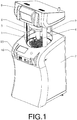
- FIG. 1 an exemplary embodiment of the machine.
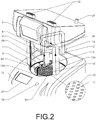
- Eyewear 1 in FIGS. 1 and 2 is shown for illustrative purposes only and is not part of the machine.
- the hollow display cabinet 2 of the machine is made of a durable, transparent material and is of sufficient size in order to accommodate the cylindrical wash chamber 3, the support bracket 4, tubing 13A, 13B, piping 14, nozzles 5A, 5B, and a diffuser 6, respectively, as shown in FIG. 2 .
- the display cabinet 2 the cylindrical wash chamber 3 must be sufficiently sized so that when the display cabinet 2 and the cylindrical wash chamber 3 are open, the user of the machine is able to insert his hands inside the display cabinet 2 and cylindrical wash chamber 3 and attach eyewear 1 to the support bracket 4.
- the display cabinet 2 is cylindrical in shape with a sliding front door (not shown) and includes a safety mechanism such that the machine's washing and cleaning operations are incapable of functioning unless the display cabinet is closed. Another safety mechanism is employed to prevent the premature closing of the cylindrical wash chamber 3 before a user removes his hands from the machine.
- the display cabinet 2 is supported by the control cabinet 7.
- the cylindrical wash chamber 3 when closed and, as shown in FIG. 2 seals to an inverted dome 8 located on the ceiling of the display cabinet 2.
- the cylindrical wash chamber has an approximate diameter of 12 inches.
- the chamber 3 is lowered vertically downward within the control cabinet 7.
- the chamber 3 is in contact with a gasket 16 to remove wash fluid droplets that adhere to its interior surface.
- the support bracket 4 comprises a stem 17, two linear bars 19, which are opposite one another and emanating from the rear edge of a disc 20, a bracket bar 21, which protrudes from the front of the disc 20 perpendicular to the linear bars 19, and a nose bridge holding assembly 18 attached to the end of the bracket bar 21 that is opposite the stem 17.
- the stem 17 is cylindrical in shape and has a length of approximately 12 inches and a diameter of approximately 0.5 inches.
- the stem 17 connects to a gear assembly 25 located in the top 9 that enables the support bracket 4 to rotate from side to side.
- the linear bars 19 can be cylindrical in shape with an approximate diameter of 0.5 inches and each have a length of approximately four inches. Further, the linear bars 19 each have, extending vertically at their outermost end, a loop 22 of adequate size to allow the arms of standard eyewear 1 to pass through each loop 22 when being secured into the support bracket 4 as shown in FIG. 2 .
- the bracket bar 21 is also rectangular in shape with an approximate length of three inches, Contained within the bracket bar 21 is a resilient member (e.g., spring 26 ) connected to the disc 20 and the nose bridge holding assembly 18.
- the nose bridge holding assembly 18 Attached at the end of the bracket bar 21, which is opposite the end attached at the disc 20, is the nose bridge holding assembly 18, which further comprises a vertically-aligned cradle or notch 23, with a fastener 24 molded into the cradle 23, which secures the eyewear 1 during operation of the machine.
- the fastener 24 is metal with a polyethylene cover.
- the support bracket 4 for the eyewear 1 is capable of accommodating eyewear 1 of varying sizes and shapes.
- the cradle 23 and the fastener 24, with a polyethylene cover further provide a slip resistant surface for the eyewear 1.
- the tensile strength of the spring connecting the holding assembly 18 and the disk 20 is calibrated to snugly clamp the nose bridge of the eyewear 1.
- the slip resistance and secure hold of the support bracket 4 elements are necessary so that the eyewear 1 remains stationary throughout the washing and drying cycles and through the various movements created by the gear assembly 25.
- the loops 22 of the support bracket 4 and the disk 20 are sized to fit the stems of eyewear 1 of varying styles and leave the eyewear 1 in an open position.
- the support bracket 4 firmly supports the eyewear 1, and because the eyewear 1 is maintained in an open position the support bracket provides the greatest available surface area for wash fluid 39 contact and cleaning purposes.
- the bottom center of the display cabinet 2 includes a drain 10 with a diameter approximately the same as the cylindrical wash chamber 3.
- the drain is underlain by a fabric filter 11.
- the top 9 is also equipped with two vent fans 12 and an antenna 29 for receiving and transmitting information.
- An operations panel 15 is situated in front of the display cabinet 2 and includes a touch screen 27 and a trackball 28 so the user can operate the machine.
- the operations panel 15 also includes a payment center 46 where the user can choose his method of payment. In the exemplary embodiment the payment center 46 allows the user to pay using cash, credit or debit card, or through an electronic transaction (e.g., smart phone application with code retrieval and input).
- the operations panel 15 is operatively connected to the computerized controller 42.
- the wash fluid reservoir 30 is made of a durable, non-corrosive material and is located at the bottom in the interior of the base cabinet 12.
- the weight of the wash fluid 39 stored in the wash fluid reservoir 30, will further aid in stabilizing the machine.
- a wash fluid quality detector 31 will be placed the wash fluid reservoir 30, as shown in FIG. 4 .
- the wash fluid reservoir 30 has a 5-gallon capacity and is a standard water bottle. Further the wash fluid quality detector measures total dissolved solid in the wash fluid 39.
- the preferred wash fluid 39 is water filtered through reverse osmosis or other filtration methods.
- a final advantage of the reverse osmosis water over other types of wash fluids is the ability to regenerate and reuse the wash fluid 39 once it is determined to be ineffective.
- the ability to reuse a large percentage of wash fluid 39 greatly increases the cost efficiency of the machine.
- the ability to use common water filtration devices to filter and recycle used wash fluid 39 allows for greater operating times between wash fluid change outs.
- a pump 32 is mounted inside the base cabinet 12.
- a suction hose 33 is attached at one end to the pump 32 and extends from the pump 32 into the wash fluid reservoir 30 near its base.
- the end of the suction hose 33 has an in-line filter 34 attached to it.
- the pump 32 will draw wash fluid 39 from the wash fluid reservoir 26, through the in-line filter 30 and through the suction hose 29.
- the wash fluid 39 is then conveyed from the pump 32 through tubing 13A, 13B, which are connected at the pump 32 outlet.
- a blower 35 is mounted in the base cabinet. As shown in FIGS.
- tubing 13A, 13B and piping 14 extend up from the pump 32 and the blower 35, respectively, through the base cabinet 12 and into the display cabinet 2.
- tubing 13A and 13B extend and connect to nozzles 5A and 5B to a point approximately 3 inches in front and behind of nose bridge holding assembly 18 when the cylindrical wash chamber 3 is closed.
- the center of the diffuser 6 will be aligned horizontally with the nose bridge holding assembly 18 and situated approximately 5 inches above the eyewear 1 when attached to support bracket 4.
- the pump 32 has an operating pressure range of at least 200 to no greater than 1,000 pounds per square inch (psi).
- the preferred application pressure is at least 250 psi and no more than 300 psi.
- an accordion drain line 36 that is attached to the catch-pan 37 that supports the cylindrical wash chamber.
- Used wash fluid 39 collects in the catch-pan 37 following the washing cycle and drains through the accordion drain line 36 into a collector 38.
- a transfer pump 40 pumps used wash fluid 39 through a filter series 41 and returns the wash fluid to the reservoir 30.
- the filter series 41 comprises an ultraviolet light filter followed by a carbon filter
- the collector 38 has a capacity of one-half gallon.
- Other filtration methods may include reverse osmosis or ion exchange and can be considered in series or in isolation depending on the filtration demand.
- the exterior of the operations panel 15 includes a trackball 28, which controls the gear assembly 25, and a touch screen 27 to allow the user to interact with the computerized controller 42.
- the machine also includes one or more audio speakers 45 which allow for audio communication with the user depending on the machine status.
- the computerized controller 42 which, as shown in FIG. 4 , is mounted in the base cabinet 12, will activate the gear assembly 25 causing the support bracket 4 to rotate side-to-side. As shown in FIG. 3 , this rotation will deflect the loops 22 approximately one inch in each direction from the support bracket's 4 starting position during both the wash cycle and drying cycle.
- the trackball 28 is both durable and the requires limited motion to be affected, and has been found by the inventor to be more appealing to young children who use the machine.
- the computerized controller 42 activates a sliding motor 43, as shown in FIG. 4 that will rotate the display cabinet 2 to an open position allowing the user to secure the eyewear 1 to the support bracket 4. Once the eyewear is secured and hands are cleared from the machine, the computerized controller 42 activates a lift motor 44 that will raise the cylindrical wash chamber 3 to a closed position. The computerized controller 42 also activates sliding motor 43 to close the display cabinet 2. The computerized controller 42 will then initiate the wash cycle by activating the pump 32 for a preset time period and then initiate the drying cycle by activating the blower 35, which operates for a preset time period.
- the computerized controller 42 activates the two vent fans 12 which will operate for a preset period to evacuate residual moisture in the cylindrical wash chamber 3.
- the computerized controller 42 completes the process by opening the cylindrical wash chamber 3 with the lift motor 44 and the display cabinet 2 with the sliding motor 43 to allow the user to remove his eyewear 1 from the support bracket 4.
- the computerized controller 42 is also capable of transmitting data and messages communicating wirelessly via the antenna 29.
- the computerized controller 42 will perform system diagnostics periodically to ensure the machine is in service. Because it is anticipated that machines will be located at various locations of greatest need, communications with a central operator or technician is necessary to ensure timely maintenance.
- the technology for the exchange of operational status information via wireless communication or wireline has been previously disclosed in applications such as US2010/0268792 .
- These systems may be integrated or utilized wholly or partially in various embodiments to maintain communications amongst the machines in service and the operator or technician.
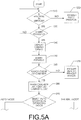
- the eyewear washing method is described with reference to FIGS. 5A & 5B .
- the method is executed by the computerized controller 42 by executing a program stored thereon when the machine is turned on.
- the computerized controller will determine whether or not the machine is in service (Step S10 ). If there is a fault in the machine (Step S10 : No) the computerized controller 42 transmits an appropriate fault message (Step S30 ) to an operator or technician. If the machine is in service (Step S10: Yes), the machine prompts the user to insert payment (Step S20 ). If payment is not received (Step S20: No), the machine returns to ready mode (Step S10 ). If payment is received (Step S20: Yes), the display cabinet 2 opens (Step S40 ) and the user inserts his eyewear 1 into the support bracket 4 (Step S50 ).
- Step S60 the user is prompted via the speakers 45 and the touch screen 27 to remove hands or articles from the machine (Step S70 ).
- Step S60: Yes the cylindrical wash chamber 3 and the display cabinet 2 will close (Step S80 ).
- Step S90 the user selects either a manual mode of operation or an optional automatic mode of operation (Step S90 ).
- the automatic mode Step S 100
- Step S90: Auto the computerized controller 42 will oscillate the support bracket 4 and the eyewear 1 throughout as wash fluid 39 is sprayed onto the eyewear for a preset time period.
- Step S110 Step S90: Manual
- the user guides the support bracket 4 with the trackball 28 to allow wash fluid 39 to come in contact with selected parts of the eyewear 1 over a preset time period.
- the drying cycle (Step S120 ) follows the wash cycle.
- the computerized controller 42 automatically oscillates the support bracket 4 and the eyewear 1 and operates the blower 35 for a preset time period.
- the computerized controller turns off the blower and activates the two vent fans 12 which again operate for a preset period to complete the drying cycle (Step S120 ).
- the cylindrical wash chamber 3 and the display cabinet 2 open (Step S130 ).
- the user removes the eyewear 1 from the machine (Step S140: Yes). If the user fails to remove his glasses (Step S140: No), the user is prompted via the speakers 45 and the touch screen 27 to remove hands and eyewear (Step S150 ). Once the user retrieves his eyewear the display cabinet 2 closes (Step S160 ).
- the computerized controller will determine if the machine remains in service. (Step S10 ) and the process is repeated.
- the machine and accompanying method described in the embodiments above provide an improvement over the related art because the machine is be readily available at locations of greatest need. Further, the machine and method are simple to use and allow the user the option to isolate wash fluid on the dirtiest part of the eyewear.
- the machine includes a display cabinet, cylindrical wash chamber, operations panel, and a control cabinet.
- a version may be presented without the touch screen 27 or the payment center 46. It is conceivable that, depending on the desired machine performance, the filter series 41 could be totally or partially bypassed or that other filtration methods may be employed. Also, because it is not critical to the operation, the display cabinet 2 could remain in the open position while the machine is operating.
Landscapes
- Physics & Mathematics (AREA)
- Health & Medical Sciences (AREA)
- General Physics & Mathematics (AREA)
- Ophthalmology & Optometry (AREA)
- Optics & Photonics (AREA)
- Cleaning By Liquid Or Steam (AREA)
- Eyeglasses (AREA)
Applications Claiming Priority (2)
| Application Number | Priority Date | Filing Date | Title |
|---|---|---|---|
| US201161469857P | 2011-03-31 | 2011-03-31 | |
| PCT/US2012/031818 WO2012135816A1 (en) | 2011-03-31 | 2012-04-02 | Eyewear washing machine and method |
Publications (2)
| Publication Number | Publication Date |
|---|---|
| EP2691807A1 EP2691807A1 (en) | 2014-02-05 |
| EP2691807B1 true EP2691807B1 (en) | 2021-10-06 |
Family
ID=46925623
Family Applications (1)
| Application Number | Title | Priority Date | Filing Date |
|---|---|---|---|
| EP12714470.7A Active EP2691807B1 (en) | 2011-03-31 | 2012-04-02 | Eyewear washing machine and method |
Country Status (6)
| Country | Link |
|---|---|
| US (1) | US9298022B2 (cg-RX-API-DMAC7.html) |
| EP (1) | EP2691807B1 (cg-RX-API-DMAC7.html) |
| JP (1) | JP5820054B2 (cg-RX-API-DMAC7.html) |
| CN (1) | CN103649822B (cg-RX-API-DMAC7.html) |
| ES (1) | ES2900747T3 (cg-RX-API-DMAC7.html) |
| WO (1) | WO2012135816A1 (cg-RX-API-DMAC7.html) |
Families Citing this family (13)
| Publication number | Priority date | Publication date | Assignee | Title |
|---|---|---|---|---|
| EP2548160B1 (en) * | 2010-03-15 | 2016-06-15 | Dolby Laboratories Licensing Corporation | 3d glasses and related systems |
| TW201136674A (en) * | 2010-04-21 | 2011-11-01 | Hon Hai Prec Ind Co Ltd | Dust elimination device |
| CN103913855B (zh) * | 2014-04-02 | 2016-02-10 | 广州市彩标立体眼镜有限公司 | 一种旋转式眼镜清洗设备及其清洗篮 |
| CN107422498B (zh) * | 2017-09-22 | 2023-11-14 | 成都阿特万超声波设备有限公司 | 一种眼镜清洗篮及清洗设备 |
| CN107656383A (zh) * | 2017-11-26 | 2018-02-02 | 宁波工程学院 | 智能助残眼镜清洗机 |
| SI25605A (sl) * | 2018-02-05 | 2019-08-30 | Xpand 3D, Logistika In Transporti, D.O.O. | Naprava in postopek za čiščenje in sušenje očal, zlasti očal za ogled 3D vsebin |
| CN109212785B (zh) * | 2018-10-27 | 2020-06-09 | 温州鑫力鞋业有限公司 | 一种影院用3d眼镜清洗装置 |
| AU2019202067B1 (en) * | 2019-03-18 | 2020-07-09 | Yantai Tanyi Crafts&Gifts Co., Ltd. | A crystal jewelry cleaning apparatus |
| CN110764282B (zh) * | 2019-11-15 | 2020-06-23 | 温州明澈眼镜科技有限公司 | 一种具有清洁功能的vr眼镜保护收纳装置 |
| CN113253488B (zh) * | 2021-05-13 | 2023-02-17 | 西安医学院第二附属医院 | 一种用于眼科护理的智能冲洗装置 |
| CN113485032B (zh) * | 2021-05-20 | 2023-05-23 | 常州大学 | 眼镜清洗装置 |
| CN114994956B (zh) * | 2022-06-16 | 2023-08-18 | 江西科强光学有限公司 | 一种眼镜片清洗、硬化、烘干一体式设备 |
| CN118455145B (zh) * | 2024-07-10 | 2024-10-01 | 武汉理工大学 | 一种可适用于不同型号vr眼镜的清洗机 |
Citations (1)
| Publication number | Priority date | Publication date | Assignee | Title |
|---|---|---|---|---|
| JP2005173452A (ja) * | 2003-12-15 | 2005-06-30 | Fujigen Kogyo Kk | 眼鏡の洗浄方法及び眼鏡の洗浄装置 |
Family Cites Families (34)
| Publication number | Priority date | Publication date | Assignee | Title |
|---|---|---|---|---|
| US1292407A (en) | 1914-02-04 | 1919-01-21 | Charles W Spicer | Cleaning-tank. |
| US3259139A (en) | 1964-05-14 | 1966-07-05 | Raymond F Bell | Spectacles cleaning unit |
| US3480022A (en) | 1967-08-25 | 1969-11-25 | Joseph W Richardson | Cleaning device for eyeglasses |
| US3552701A (en) * | 1968-07-02 | 1971-01-05 | Anthony Montagano | Interior auto mirror support for sunglasses or the like |
| FR2351631A1 (fr) * | 1976-05-20 | 1977-12-16 | Guichard Ets Rene | Dispositif de support pour la presentation de lunettes |
| US4034432A (en) | 1976-06-08 | 1977-07-12 | Sullivan James M | Spectacle cleaning apparatus |
| US4112955A (en) * | 1977-01-21 | 1978-09-12 | Gollel Richard M | Coin operated ultrasonic cleaning device |
| JPS546953U (cg-RX-API-DMAC7.html) | 1977-06-16 | 1979-01-17 | ||
| US4196487A (en) | 1978-11-06 | 1980-04-08 | Merriman Henry H | Eyeglass washer |
| JPS59118305U (ja) | 1983-01-25 | 1984-08-09 | マスプロ電工株式会社 | 車両用アンテナ取付具 |
| JPS6076554U (ja) | 1983-11-02 | 1985-05-29 | 日本電気株式会社 | 自動車用後方対物距離表示装置 |
| JPS6133025U (ja) * | 1984-07-30 | 1986-02-28 | オムロン株式会社 | メガネ洗浄等自動サ−ビス機 |
| JPS61193430U (cg-RX-API-DMAC7.html) * | 1985-05-23 | 1986-12-02 | ||
| IL93174A0 (en) * | 1990-01-25 | 1990-11-05 | Avi Mor | Apparatus for washing lenses and method for same |
| DE9002566U1 (de) * | 1990-03-06 | 1990-05-10 | Creutz, Hans-Werner, 5040 Brühl | Halter mit Stellkörper, insbesondere für Brillengestelle, Brillenauflagegestelle od.dgl. |
| FI95970C (fi) * | 1993-03-19 | 1996-04-10 | Surita Oy | Silmälasien pesulaite |
| US5335394A (en) * | 1993-10-20 | 1994-08-09 | Cunningham Jr James W | Eyeglass cleaning apparatus |
| JPH103062A (ja) * | 1996-06-18 | 1998-01-06 | Nikon Corp | コンタクトレンズ洗浄装置 |
| US5794635A (en) * | 1997-01-29 | 1998-08-18 | Maines; Kenneth E. | Eye glass cleaning machine |
| JPH11128777A (ja) * | 1997-11-04 | 1999-05-18 | Sony Corp | 高圧純水発生装置及びこれを用いた洗浄装置 |
| JPH11333498A (ja) * | 1998-05-27 | 1999-12-07 | Toshimitsu Hattori | 純水の製造方法 |
| JP3250154B2 (ja) * | 1999-03-31 | 2002-01-28 | 株式会社スーパーシリコン研究所 | 半導体ウエハ製造装置 |
| US6338350B1 (en) | 1999-08-16 | 2002-01-15 | Paul Ewen | Portable eyeglass washing system |
| US6415803B1 (en) * | 1999-10-06 | 2002-07-09 | Z Cap, L.L.C. | Method and apparatus for semiconductor wafer cleaning with reuse of chemicals |
| US6857957B2 (en) * | 2001-05-09 | 2005-02-22 | Daniel Marks | Poker game with 2 reward cards that adjust paytable |
| US6539957B1 (en) * | 2001-08-31 | 2003-04-01 | Abel Morales, Jr. | Eyewear cleaning apparatus |
| DE10154161A1 (de) * | 2001-11-03 | 2003-05-15 | Peter Diehl | Vorrichtung zur Trocknung von Brillengläsern |
| US20030136429A1 (en) * | 2002-01-22 | 2003-07-24 | Semitool, Inc. | Vapor cleaning and liquid rinsing process vessel |
| US6938628B2 (en) * | 2002-04-26 | 2005-09-06 | James Cooley | Eyeglass cleaning station |
| EP1382990B1 (fr) | 2002-07-18 | 2006-01-04 | Special Coating Laboratory International (S.C.L. International) S.A.R.L. | Machine de nettoyage de verres de lunettes ou autres pièces similaires |
| US7000267B2 (en) * | 2003-06-03 | 2006-02-21 | Thomas Peter Chesters | Portable recyclable fluid flushing method |
| KR100910036B1 (ko) * | 2004-06-29 | 2009-07-30 | 가부시키가이샤 가고시마쵸온파소고겐큐쇼 | 초음파 세정방법 및 장치 |
| GR1006703B (el) * | 2008-05-16 | 2010-02-19 | Αυτοματο πλυντηριο και στεγνωτηριο κρανους που λειτουργει με κερματοδεκτη ή ηλεκτρονικη καρτα | |
| WO2010120815A1 (en) | 2009-04-13 | 2010-10-21 | Crane Merchandising Systems, Inc. | Vending machine with interactive display |
-
2012
- 2012-04-02 CN CN201280017106.1A patent/CN103649822B/zh active Active
- 2012-04-02 US US13/437,238 patent/US9298022B2/en active Active
- 2012-04-02 JP JP2014502903A patent/JP5820054B2/ja active Active
- 2012-04-02 ES ES12714470T patent/ES2900747T3/es active Active
- 2012-04-02 WO PCT/US2012/031818 patent/WO2012135816A1/en not_active Ceased
- 2012-04-02 EP EP12714470.7A patent/EP2691807B1/en active Active
Patent Citations (1)
| Publication number | Priority date | Publication date | Assignee | Title |
|---|---|---|---|---|
| JP2005173452A (ja) * | 2003-12-15 | 2005-06-30 | Fujigen Kogyo Kk | 眼鏡の洗浄方法及び眼鏡の洗浄装置 |
Also Published As
| Publication number | Publication date |
|---|---|
| HK1196025A1 (zh) | 2014-11-28 |
| EP2691807A1 (en) | 2014-02-05 |
| WO2012135816A1 (en) | 2012-10-04 |
| JP2014510957A (ja) | 2014-05-01 |
| CN103649822B (zh) | 2015-07-29 |
| US9298022B2 (en) | 2016-03-29 |
| CN103649822A (zh) | 2014-03-19 |
| JP5820054B2 (ja) | 2015-11-24 |
| US20120247517A1 (en) | 2012-10-04 |
| ES2900747T3 (es) | 2022-03-18 |
Similar Documents
| Publication | Publication Date | Title |
|---|---|---|
| EP2691807B1 (en) | Eyewear washing machine and method | |
| US9550216B2 (en) | Jewelry washing machine and method | |
| JP2014510957A5 (cg-RX-API-DMAC7.html) | ||
| AU597617B2 (en) | Produce hydration system | |
| US6647997B2 (en) | Paint gun washer | |
| EP2030730B1 (en) | Eyeglass lens processing apparatus | |
| JP2000140784A (ja) | 水泳プ―ル掃除機 | |
| CN105266745B (zh) | 洗碟机 | |
| JP2005173452A (ja) | 眼鏡の洗浄方法及び眼鏡の洗浄装置 | |
| JP4579633B2 (ja) | レンズの洗浄装置 | |
| HK1196025B (en) | Eyewear washing machine and method | |
| CN101770083A (zh) | 眼镜清洁器 | |
| CN211488811U (zh) | 一种眼镜清洗消毒装置 | |
| CN111812865A (zh) | 一种眼镜清洗机 | |
| KR20230099222A (ko) | 정수기 | |
| KR101805364B1 (ko) | 세정액 공급제어가 가능한 안경세척 시스템 | |
| EP2331322A2 (en) | Lens handling in automated lens-coating systems | |
| CN209746692U (zh) | 一种便于清洁的商场售卖机 | |
| KR101150501B1 (ko) | 천정형 공기 조화기 세척 시스템 및 이를 이용한 공기 조화기 세척 방법 | |
| CN218284924U (zh) | 光学镜片加工研磨机 | |
| KR20060115091A (ko) | 네트워크를 이용한 통합 관리 기능을 갖는 간이 자동 세차시스템 | |
| CN119260530B (zh) | 一种光学零件加工用抛光装置 | |
| KR20240173781A (ko) | 물이 불필요한 간편 세차 클리너 | |
| KR101844223B1 (ko) | 식기세척기 | |
| KR20110135910A (ko) | 수처리 기기의 세척방법 |
Legal Events
| Date | Code | Title | Description |
|---|---|---|---|
| PUAI | Public reference made under article 153(3) epc to a published international application that has entered the european phase |
Free format text: ORIGINAL CODE: 0009012 |
|
| 17P | Request for examination filed |
Effective date: 20130927 |
|
| AK | Designated contracting states |
Kind code of ref document: A1 Designated state(s): AL AT BE BG CH CY CZ DE DK EE ES FI FR GB GR HR HU IE IS IT LI LT LU LV MC MK MT NL NO PL PT RO RS SE SI SK SM TR |
|
| DAX | Request for extension of the european patent (deleted) | ||
| STAA | Information on the status of an ep patent application or granted ep patent |
Free format text: STATUS: EXAMINATION IS IN PROGRESS |
|
| 17Q | First examination report despatched |
Effective date: 20170522 |
|
| GRAP | Despatch of communication of intention to grant a patent |
Free format text: ORIGINAL CODE: EPIDOSNIGR1 |
|
| STAA | Information on the status of an ep patent application or granted ep patent |
Free format text: STATUS: GRANT OF PATENT IS INTENDED |
|
| INTG | Intention to grant announced |
Effective date: 20210426 |
|
| GRAS | Grant fee paid |
Free format text: ORIGINAL CODE: EPIDOSNIGR3 |
|
| GRAA | (expected) grant |
Free format text: ORIGINAL CODE: 0009210 |
|
| STAA | Information on the status of an ep patent application or granted ep patent |
Free format text: STATUS: THE PATENT HAS BEEN GRANTED |
|
| AK | Designated contracting states |
Kind code of ref document: B1 Designated state(s): AL AT BE BG CH CY CZ DE DK EE ES FI FR GB GR HR HU IE IS IT LI LT LU LV MC MK MT NL NO PL PT RO RS SE SI SK SM TR |
|
| REG | Reference to a national code |
Ref country code: GB Ref legal event code: FG4D |
|
| REG | Reference to a national code |
Ref country code: CH Ref legal event code: EP Ref country code: AT Ref legal event code: REF Ref document number: 1436727 Country of ref document: AT Kind code of ref document: T Effective date: 20211015 |
|
| REG | Reference to a national code |
Ref country code: DE Ref legal event code: R096 Ref document number: 602012076849 Country of ref document: DE |
|
| REG | Reference to a national code |
Ref country code: IE Ref legal event code: FG4D |
|
| REG | Reference to a national code |
Ref country code: SE Ref legal event code: TRGR |
|
| REG | Reference to a national code |
Ref country code: LT Ref legal event code: MG9D |
|
| REG | Reference to a national code |
Ref country code: NL Ref legal event code: MP Effective date: 20211006 |
|
| REG | Reference to a national code |
Ref country code: AT Ref legal event code: MK05 Ref document number: 1436727 Country of ref document: AT Kind code of ref document: T Effective date: 20211006 |
|
| REG | Reference to a national code |
Ref country code: ES Ref legal event code: FG2A Ref document number: 2900747 Country of ref document: ES Kind code of ref document: T3 Effective date: 20220318 |
|
| PG25 | Lapsed in a contracting state [announced via postgrant information from national office to epo] |
Ref country code: RS Free format text: LAPSE BECAUSE OF FAILURE TO SUBMIT A TRANSLATION OF THE DESCRIPTION OR TO PAY THE FEE WITHIN THE PRESCRIBED TIME-LIMIT Effective date: 20211006 Ref country code: LT Free format text: LAPSE BECAUSE OF FAILURE TO SUBMIT A TRANSLATION OF THE DESCRIPTION OR TO PAY THE FEE WITHIN THE PRESCRIBED TIME-LIMIT Effective date: 20211006 Ref country code: FI Free format text: LAPSE BECAUSE OF FAILURE TO SUBMIT A TRANSLATION OF THE DESCRIPTION OR TO PAY THE FEE WITHIN THE PRESCRIBED TIME-LIMIT Effective date: 20211006 Ref country code: BG Free format text: LAPSE BECAUSE OF FAILURE TO SUBMIT A TRANSLATION OF THE DESCRIPTION OR TO PAY THE FEE WITHIN THE PRESCRIBED TIME-LIMIT Effective date: 20220106 Ref country code: AT Free format text: LAPSE BECAUSE OF FAILURE TO SUBMIT A TRANSLATION OF THE DESCRIPTION OR TO PAY THE FEE WITHIN THE PRESCRIBED TIME-LIMIT Effective date: 20211006 |
|
| PG25 | Lapsed in a contracting state [announced via postgrant information from national office to epo] |
Ref country code: IS Free format text: LAPSE BECAUSE OF FAILURE TO SUBMIT A TRANSLATION OF THE DESCRIPTION OR TO PAY THE FEE WITHIN THE PRESCRIBED TIME-LIMIT Effective date: 20220206 Ref country code: PT Free format text: LAPSE BECAUSE OF FAILURE TO SUBMIT A TRANSLATION OF THE DESCRIPTION OR TO PAY THE FEE WITHIN THE PRESCRIBED TIME-LIMIT Effective date: 20220207 Ref country code: PL Free format text: LAPSE BECAUSE OF FAILURE TO SUBMIT A TRANSLATION OF THE DESCRIPTION OR TO PAY THE FEE WITHIN THE PRESCRIBED TIME-LIMIT Effective date: 20211006 Ref country code: NO Free format text: LAPSE BECAUSE OF FAILURE TO SUBMIT A TRANSLATION OF THE DESCRIPTION OR TO PAY THE FEE WITHIN THE PRESCRIBED TIME-LIMIT Effective date: 20220106 Ref country code: NL Free format text: LAPSE BECAUSE OF FAILURE TO SUBMIT A TRANSLATION OF THE DESCRIPTION OR TO PAY THE FEE WITHIN THE PRESCRIBED TIME-LIMIT Effective date: 20211006 Ref country code: LV Free format text: LAPSE BECAUSE OF FAILURE TO SUBMIT A TRANSLATION OF THE DESCRIPTION OR TO PAY THE FEE WITHIN THE PRESCRIBED TIME-LIMIT Effective date: 20211006 Ref country code: HR Free format text: LAPSE BECAUSE OF FAILURE TO SUBMIT A TRANSLATION OF THE DESCRIPTION OR TO PAY THE FEE WITHIN THE PRESCRIBED TIME-LIMIT Effective date: 20211006 Ref country code: GR Free format text: LAPSE BECAUSE OF FAILURE TO SUBMIT A TRANSLATION OF THE DESCRIPTION OR TO PAY THE FEE WITHIN THE PRESCRIBED TIME-LIMIT Effective date: 20220107 |
|
| REG | Reference to a national code |
Ref country code: DE Ref legal event code: R097 Ref document number: 602012076849 Country of ref document: DE |
|
| PG25 | Lapsed in a contracting state [announced via postgrant information from national office to epo] |
Ref country code: SM Free format text: LAPSE BECAUSE OF FAILURE TO SUBMIT A TRANSLATION OF THE DESCRIPTION OR TO PAY THE FEE WITHIN THE PRESCRIBED TIME-LIMIT Effective date: 20211006 Ref country code: SK Free format text: LAPSE BECAUSE OF FAILURE TO SUBMIT A TRANSLATION OF THE DESCRIPTION OR TO PAY THE FEE WITHIN THE PRESCRIBED TIME-LIMIT Effective date: 20211006 Ref country code: RO Free format text: LAPSE BECAUSE OF FAILURE TO SUBMIT A TRANSLATION OF THE DESCRIPTION OR TO PAY THE FEE WITHIN THE PRESCRIBED TIME-LIMIT Effective date: 20211006 Ref country code: EE Free format text: LAPSE BECAUSE OF FAILURE TO SUBMIT A TRANSLATION OF THE DESCRIPTION OR TO PAY THE FEE WITHIN THE PRESCRIBED TIME-LIMIT Effective date: 20211006 Ref country code: DK Free format text: LAPSE BECAUSE OF FAILURE TO SUBMIT A TRANSLATION OF THE DESCRIPTION OR TO PAY THE FEE WITHIN THE PRESCRIBED TIME-LIMIT Effective date: 20211006 Ref country code: CZ Free format text: LAPSE BECAUSE OF FAILURE TO SUBMIT A TRANSLATION OF THE DESCRIPTION OR TO PAY THE FEE WITHIN THE PRESCRIBED TIME-LIMIT Effective date: 20211006 |
|
| PLBE | No opposition filed within time limit |
Free format text: ORIGINAL CODE: 0009261 |
|
| STAA | Information on the status of an ep patent application or granted ep patent |
Free format text: STATUS: NO OPPOSITION FILED WITHIN TIME LIMIT |
|
| 26N | No opposition filed |
Effective date: 20220707 |
|
| PG25 | Lapsed in a contracting state [announced via postgrant information from national office to epo] |
Ref country code: AL Free format text: LAPSE BECAUSE OF FAILURE TO SUBMIT A TRANSLATION OF THE DESCRIPTION OR TO PAY THE FEE WITHIN THE PRESCRIBED TIME-LIMIT Effective date: 20211006 |
|
| PG25 | Lapsed in a contracting state [announced via postgrant information from national office to epo] |
Ref country code: SI Free format text: LAPSE BECAUSE OF FAILURE TO SUBMIT A TRANSLATION OF THE DESCRIPTION OR TO PAY THE FEE WITHIN THE PRESCRIBED TIME-LIMIT Effective date: 20211006 |
|
| REG | Reference to a national code |
Ref country code: BE Ref legal event code: MM Effective date: 20220430 |
|
| PG25 | Lapsed in a contracting state [announced via postgrant information from national office to epo] |
Ref country code: MC Free format text: LAPSE BECAUSE OF FAILURE TO SUBMIT A TRANSLATION OF THE DESCRIPTION OR TO PAY THE FEE WITHIN THE PRESCRIBED TIME-LIMIT Effective date: 20211006 Ref country code: LU Free format text: LAPSE BECAUSE OF NON-PAYMENT OF DUE FEES Effective date: 20220402 |
|
| PG25 | Lapsed in a contracting state [announced via postgrant information from national office to epo] |
Ref country code: BE Free format text: LAPSE BECAUSE OF NON-PAYMENT OF DUE FEES Effective date: 20220430 |
|
| PG25 | Lapsed in a contracting state [announced via postgrant information from national office to epo] |
Ref country code: IE Free format text: LAPSE BECAUSE OF NON-PAYMENT OF DUE FEES Effective date: 20220402 |
|
| P01 | Opt-out of the competence of the unified patent court (upc) registered |
Effective date: 20230525 |
|
| PG25 | Lapsed in a contracting state [announced via postgrant information from national office to epo] |
Ref country code: HU Free format text: LAPSE BECAUSE OF FAILURE TO SUBMIT A TRANSLATION OF THE DESCRIPTION OR TO PAY THE FEE WITHIN THE PRESCRIBED TIME-LIMIT; INVALID AB INITIO Effective date: 20120402 |
|
| PG25 | Lapsed in a contracting state [announced via postgrant information from national office to epo] |
Ref country code: MK Free format text: LAPSE BECAUSE OF FAILURE TO SUBMIT A TRANSLATION OF THE DESCRIPTION OR TO PAY THE FEE WITHIN THE PRESCRIBED TIME-LIMIT Effective date: 20211006 Ref country code: CY Free format text: LAPSE BECAUSE OF FAILURE TO SUBMIT A TRANSLATION OF THE DESCRIPTION OR TO PAY THE FEE WITHIN THE PRESCRIBED TIME-LIMIT Effective date: 20211006 |
|
| PG25 | Lapsed in a contracting state [announced via postgrant information from national office to epo] |
Ref country code: TR Free format text: LAPSE BECAUSE OF FAILURE TO SUBMIT A TRANSLATION OF THE DESCRIPTION OR TO PAY THE FEE WITHIN THE PRESCRIBED TIME-LIMIT Effective date: 20211006 |
|
| PG25 | Lapsed in a contracting state [announced via postgrant information from national office to epo] |
Ref country code: MT Free format text: LAPSE BECAUSE OF FAILURE TO SUBMIT A TRANSLATION OF THE DESCRIPTION OR TO PAY THE FEE WITHIN THE PRESCRIBED TIME-LIMIT Effective date: 20211006 |
|
| PGFP | Annual fee paid to national office [announced via postgrant information from national office to epo] |
Ref country code: GB Payment date: 20250306 Year of fee payment: 14 |
|
| PGFP | Annual fee paid to national office [announced via postgrant information from national office to epo] |
Ref country code: DE Payment date: 20250422 Year of fee payment: 14 |
|
| PGFP | Annual fee paid to national office [announced via postgrant information from national office to epo] |
Ref country code: ES Payment date: 20250529 Year of fee payment: 14 |
|
| PGFP | Annual fee paid to national office [announced via postgrant information from national office to epo] |
Ref country code: IT Payment date: 20250422 Year of fee payment: 14 |
|
| PGFP | Annual fee paid to national office [announced via postgrant information from national office to epo] |
Ref country code: FR Payment date: 20250425 Year of fee payment: 14 |
|
| PGFP | Annual fee paid to national office [announced via postgrant information from national office to epo] |
Ref country code: CH Payment date: 20250501 Year of fee payment: 14 |
|
| PGFP | Annual fee paid to national office [announced via postgrant information from national office to epo] |
Ref country code: SE Payment date: 20250429 Year of fee payment: 14 |