EP2690295B1 - Palier de bronze avec flasque - Google Patents
Palier de bronze avec flasque Download PDFInfo
- Publication number
- EP2690295B1 EP2690295B1 EP12719922.2A EP12719922A EP2690295B1 EP 2690295 B1 EP2690295 B1 EP 2690295B1 EP 12719922 A EP12719922 A EP 12719922A EP 2690295 B1 EP2690295 B1 EP 2690295B1
- Authority
- EP
- European Patent Office
- Prior art keywords
- bearing
- protrusions
- bronze bushing
- axial
- recesses
- Prior art date
- Legal status (The legal status is an assumption and is not a legal conclusion. Google has not performed a legal analysis and makes no representation as to the accuracy of the status listed.)
- Not-in-force
Links
- 229910000906 Bronze Inorganic materials 0.000 title claims description 57
- 239000010974 bronze Substances 0.000 title claims description 57
- KUNSUQLRTQLHQQ-UHFFFAOYSA-N copper tin Chemical group [Cu].[Sn] KUNSUQLRTQLHQQ-UHFFFAOYSA-N 0.000 title claims description 57
- 239000004033 plastic Substances 0.000 claims description 16
- 239000000463 material Substances 0.000 description 16
- 238000000034 method Methods 0.000 description 11
- 230000008569 process Effects 0.000 description 11
- 230000033001 locomotion Effects 0.000 description 8
- 238000004519 manufacturing process Methods 0.000 description 8
- 230000005489 elastic deformation Effects 0.000 description 5
- 230000008901 benefit Effects 0.000 description 4
- 238000002485 combustion reaction Methods 0.000 description 4
- 230000005540 biological transmission Effects 0.000 description 3
- 150000002500 ions Chemical class 0.000 description 3
- 230000002265 prevention Effects 0.000 description 3
- 230000009471 action Effects 0.000 description 2
- 238000004026 adhesive bonding Methods 0.000 description 2
- 238000006243 chemical reaction Methods 0.000 description 2
- 210000000078 claw Anatomy 0.000 description 2
- 238000013461 design Methods 0.000 description 2
- 238000012423 maintenance Methods 0.000 description 2
- 230000014759 maintenance of location Effects 0.000 description 2
- 238000003466 welding Methods 0.000 description 2
- KRHYYFGTRYWZRS-UHFFFAOYSA-M Fluoride anion Chemical compound [F-] KRHYYFGTRYWZRS-UHFFFAOYSA-M 0.000 description 1
- 230000008859 change Effects 0.000 description 1
- 238000011161 development Methods 0.000 description 1
- 238000009826 distribution Methods 0.000 description 1
- 230000000694 effects Effects 0.000 description 1
- 239000003822 epoxy resin Substances 0.000 description 1
- 229920002313 fluoropolymer Polymers 0.000 description 1
- 239000004811 fluoropolymer Substances 0.000 description 1
- 238000003780 insertion Methods 0.000 description 1
- 230000037431 insertion Effects 0.000 description 1
- 230000003993 interaction Effects 0.000 description 1
- 229910000765 intermetallic Inorganic materials 0.000 description 1
- 239000000088 plastic resin Substances 0.000 description 1
- 229920000647 polyepoxide Polymers 0.000 description 1
- 230000000135 prohibitive effect Effects 0.000 description 1
- 230000009467 reduction Effects 0.000 description 1
- 238000010008 shearing Methods 0.000 description 1
- 238000005476 soldering Methods 0.000 description 1
Images


Classifications
-
- F—MECHANICAL ENGINEERING; LIGHTING; HEATING; WEAPONS; BLASTING
- F16—ENGINEERING ELEMENTS AND UNITS; GENERAL MEASURES FOR PRODUCING AND MAINTAINING EFFECTIVE FUNCTIONING OF MACHINES OR INSTALLATIONS; THERMAL INSULATION IN GENERAL
- F16C—SHAFTS; FLEXIBLE SHAFTS; ELEMENTS OR CRANKSHAFT MECHANISMS; ROTARY BODIES OTHER THAN GEARING ELEMENTS; BEARINGS
- F16C17/00—Sliding-contact bearings for exclusively rotary movement
- F16C17/10—Sliding-contact bearings for exclusively rotary movement for both radial and axial load
-
- F—MECHANICAL ENGINEERING; LIGHTING; HEATING; WEAPONS; BLASTING
- F16—ENGINEERING ELEMENTS AND UNITS; GENERAL MEASURES FOR PRODUCING AND MAINTAINING EFFECTIVE FUNCTIONING OF MACHINES OR INSTALLATIONS; THERMAL INSULATION IN GENERAL
- F16C—SHAFTS; FLEXIBLE SHAFTS; ELEMENTS OR CRANKSHAFT MECHANISMS; ROTARY BODIES OTHER THAN GEARING ELEMENTS; BEARINGS
- F16C33/00—Parts of bearings; Special methods for making bearings or parts thereof
- F16C33/02—Parts of sliding-contact bearings
- F16C33/04—Brasses; Bushes; Linings
- F16C33/046—Brasses; Bushes; Linings divided or split, e.g. half-bearings or rolled sleeves
-
- F—MECHANICAL ENGINEERING; LIGHTING; HEATING; WEAPONS; BLASTING
- F16—ENGINEERING ELEMENTS AND UNITS; GENERAL MEASURES FOR PRODUCING AND MAINTAINING EFFECTIVE FUNCTIONING OF MACHINES OR INSTALLATIONS; THERMAL INSULATION IN GENERAL
- F16C—SHAFTS; FLEXIBLE SHAFTS; ELEMENTS OR CRANKSHAFT MECHANISMS; ROTARY BODIES OTHER THAN GEARING ELEMENTS; BEARINGS
- F16C43/00—Assembling bearings
- F16C43/02—Assembling sliding-contact bearings
-
- F—MECHANICAL ENGINEERING; LIGHTING; HEATING; WEAPONS; BLASTING
- F16—ENGINEERING ELEMENTS AND UNITS; GENERAL MEASURES FOR PRODUCING AND MAINTAINING EFFECTIVE FUNCTIONING OF MACHINES OR INSTALLATIONS; THERMAL INSULATION IN GENERAL
- F16C—SHAFTS; FLEXIBLE SHAFTS; ELEMENTS OR CRANKSHAFT MECHANISMS; ROTARY BODIES OTHER THAN GEARING ELEMENTS; BEARINGS
- F16C9/00—Bearings for crankshafts or connecting-rods; Attachment of connecting-rods
- F16C9/02—Crankshaft bearings
-
- F—MECHANICAL ENGINEERING; LIGHTING; HEATING; WEAPONS; BLASTING
- F16—ENGINEERING ELEMENTS AND UNITS; GENERAL MEASURES FOR PRODUCING AND MAINTAINING EFFECTIVE FUNCTIONING OF MACHINES OR INSTALLATIONS; THERMAL INSULATION IN GENERAL
- F16C—SHAFTS; FLEXIBLE SHAFTS; ELEMENTS OR CRANKSHAFT MECHANISMS; ROTARY BODIES OTHER THAN GEARING ELEMENTS; BEARINGS
- F16C2226/00—Joining parts; Fastening; Assembling or mounting parts
- F16C2226/50—Positive connections
- F16C2226/70—Positive connections with complementary interlocking parts
- F16C2226/76—Positive connections with complementary interlocking parts with tongue and groove or key and slot
-
- F—MECHANICAL ENGINEERING; LIGHTING; HEATING; WEAPONS; BLASTING
- F16—ENGINEERING ELEMENTS AND UNITS; GENERAL MEASURES FOR PRODUCING AND MAINTAINING EFFECTIVE FUNCTIONING OF MACHINES OR INSTALLATIONS; THERMAL INSULATION IN GENERAL
- F16C—SHAFTS; FLEXIBLE SHAFTS; ELEMENTS OR CRANKSHAFT MECHANISMS; ROTARY BODIES OTHER THAN GEARING ELEMENTS; BEARINGS
- F16C2360/00—Engines or pumps
- F16C2360/22—Internal combustion engines
Definitions
- the present invention relates to a flanged bronze bushing used on internal combustion engines, provided with a sliding bearing coupled to an axial bearing by fixation means that undergo plastic deformation.
- a flanged bearing according to the preamble of claim 1 is known from WO 93/17250 A . Due to the need for higher combustion pressure, which leads to the employ of greater force for closing the clutch while changing gears, and consequently to a greater reaction on the internal axial bearings, the Diesel and Otto engines have to increase the axial load on the surface of the crankshaft disk. As a result, the axial reactions on slide bearings that use flanges will also undergo an increase in load, which impairs the product life, if the product is not developed property.
- the first restriction bears the stresses generated by friction between the rest disk of the crankshaft and the slide surface of the axial bearing, friction torque.
- the second restriction prevents the flange from detaching totally and falling onto the driving axle.
- the third restriction is axial and bears the vibration stresses of the driving axle. All these restrictions should guarantee that the flange will not detach during transportation until the assembling of the machine, or during the useful life thereof.
- Patent document US4076342 relates to a flange that has, in its internal diameter, a thinner section that is received in a channel in the back of the bronze bearing, on the steal side, guaranteeing retention in the axial direction.
- the fixation device has two protrusions located at the flange ends and two recesses that are made in the bronze bearing as well. With radial mounting, the bronze bearing deforms and enables the recesses at the ends to receive the flange protrusions, thus fitting into the channel the thin flange section.
- Patent document US4533261 relates to the mounting of the flange in a direction radial to the bronze bushing and the mounting process is an interaction of the rigidity of the bronze bushing with that of the flange.
- the flange has two spaced-apart protrusions close to the ends, provided with convex prisms, which are responsible for fixing the parts, under cooperation of the recesses in the form of a hook on the bronze bushing.
- the mounting if of the click-type, working with the two elements bronze bushing and flange, in the elastic phase, since if one presses the flange protrusions exactly onto the recesses on the bronze bushing, both flange and bronze bushing give way and enable the protrusions to fit into the recesses.
- Patent document GB2210113 relates to a solution in which the flange is mounted on the bronze bushing in radial direction, wherein the first protrusion to fit is a central one, and by elastic deformation of the bronze bushing, other points at the flange end fit into cooperating recesses at the end thereof, which may be dovetail-shaped, chamfered or notched, made at the time of stamping the bronze bushing.
- Patent document GB2225392 relates to a solution having only one flange fixing protrusion, located in the center, mounted axially and locked in a plastic manner by action of punches on the side of the bronze bushing.
- the protrusion has side chamfers formed at the time of stamping, which serve as a support to receive the plastically deformed material of the bronze bushing, through punches, close to the protrusion, on the side of the bronze bushing.
- Patent document GB2241752 relates to a solution in which the flange has protrusions that are deformed into the recesses of the bushing, which in turn undergo the external action, opening the material at the side of the flange protrusions in the bushing region, thus fixing them.
- Patent document DE4041557 relates to a solution of radial mounting by elastic deformation of the bronze bushing, thus enabling the introduction of hook-shaped recesses, which engage with recesses on the bronze bushing.
- Brazilian Patent document PI 0703980-8 presents a solution with radial mounting by elastic deformation of a radial bearing, which can be attached, fitted, or even mounted, enabling relative movements, on the side of the bronze bushing, of designated elastic fixation claws, which are extensions of the inner diameter, having corresponding cooperating geometry recesses on the slide bearing.
- a flanged bronze bushing containing a slide bearing may be a bronze bushing or a bushing that enables one to mount at least one axial bearing in the form of a flange that can be attached, fitted or even mounted, enabling relative movements of plastic fixation claws with respect to each other, which are designated herein as deformable protrusions and are extensions of the inner diameter, having corresponding cooperating geometry recesses on the slide bearing.
- a polymeric flange on a slide bearing of a metallic compound or vice-versa both having tribologic properties suitable to the application thus contributing to the technological development of the machines.
- the present invention relates to a flanged bronze bushing 100, for use on internal combustion engine, particularly on the crankshaft.
- a flanged bronze bushing 100 for use on internal combustion engine, particularly on the crankshaft.
- Such use is due to the fact that, when the vehicle is in motion or geared, the transmission remains coupled to the motor by means of the clutch, which, in its essence, uses the crankshaft as a support point to promote the uncoupling of the engine from the transmission, which results from stepping on the vehicle clutch, thus enabling gear change. It is at this moment that the crankshaft undergoes a great axial stress, reflecting the stress to the axial bearing, known also as flange.
- the flanged bronze bushing 100 of the present invention was invented with a view to enable perfect functioning of moveable parts, minimizing friction and guaranteeing movement with respective the transmission of force.
- the flanged bronze bushing 200 of the prior art comprises an axial bearing 20, provided with resilient protrusions 30 and a slide bearing 10, provided with recesses 40 for receiving the resilient protrusions 30.
- the final configuration of the flanged bronze bushing 200 is achieved by mounting the axial bearing 200 on the slide bearing 10. Such a mounting takes place due to the elastic deformation of the protrusions 30 for passing through the recess 40 trapeze and then the protrusions 30 are released, so that the will return to the original non-deformed state, fitting into the recesses 40 and enabling the dismounting thereof.
- This mounting is only possible because the protrusions 30 have such a characteristic that enable them to undergo a stress and return to their initial position, that is, allow them to undergo resilient or elastic deformation, known also as spring effect.
- the object of the present invention tends to solve the problem of resistance to the axial stresses caused by movement of the crankshaft, by means of a flanged bronze bushing 100 provided with a type of fixation in which the protrusions of the axial bearing are deformed during the mounting and do not return to the initial position, that is, taking on a new position, the final position, after they are mounted on the slide bearing.
- the difference between the initial position and the final position is a plastic deformation ⁇ X, which may range from 0.1 to 2.0mm and preferably from 0.1 to 1.0mm.
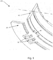
- Figure 8 shows a plastic deformation ⁇ X of the protrusions 3 by a value of about 0.14mm.
- Figure 2 illustrates one first possible embodiment of the flanged bronze bushing 100 of the present invention, which comprises basically a slide bearing 1 and an axial bearing 2. This figure has a position before the mounting, that is, before the deformable protrusions 3 are inserted into the fixation recess 4.
- the slide bearing 1 has three recesses on each side, arranged in its side regions 6 or thickness, wherein two recesses are inclined 4 and one recess being fix 4' on each side.
- the fixed recess 4' has a shape resembling an inclined square (with inclined side walls), each of them being provided with two inclined side walls, one of the walls having an angle between it and the base ranging from 100° to 170°, preferably 135°, and an angle between the other side wall and the base ranging from 15° to 60°, preferably 45°.
- the axial bearing 2 has deformable fixation protrusions 3. formed by eliminating material around it, apart from the base, which maintains it as part of the axial bearing 2.
- the protrusions 3 are nothing else than the think elements that resemble a finger, the geometry of which is intended to guarantee their plasticity as a function of the materials employed.
- the adjacent spaces 5 are regions where the protrusions 3 are deformed by a measure defined in the design of the piece, so as to flow within the flow limits of the materials, without reaching the break limit of the materials employed, thus taking on a new position.
- the adjacent space 5 will also serve for withdrawal of the axial bearing 2 at a moment of maintenance.
- the deformation for mounting the deformable protrusions 3 into the space 5 is effected by an external force F, as shown in Figure 3 .
- Figure 3 illustrates a detail of one of the inclined recesses 4 provided with two side walls, one of them having smaller angles ranging from 15° to 60° and that serve as stops to catch the deformable protrusions 3 of the axial bearing 2, and the other wall having larger angles ranging from 100° to 170° and that serve aid the deformable protrusions 3 in undergoing plastic deformation, taking on a different position as compared with the position before the mounting.
- the configuration of the two walls, together with the surfaces 10 cause the deformable protrusions 3 to be caught by the stops 9.
- the recesses 4 have the function of preventing release of the axial bearing 2 and of the slide bearing 1 in directions X (rotation), Y (axial) and Z (radial). The prevention takes place due to the form of the stop 9, which has an angle suitable for this function.
- the angle has a geometry cooperating with that of the surface 10, which is at the end of the deformable fixation protrusions 3.
- the recesses 4 and the deformable protrusions 3 match, they cooperate with each other, causing the axial bearing 2 to engage with the slide bearing 1, thus preventing them from detaching from each other.
- the prevention takes place due to the form of the stop 9, which as an angle suitable for this function.
- the angle has a geometry cooperating with that of the surface 10, which is at the end of the deformable fixation protrusions 3, as shown in figure 4 .
- Figure 5 illustrates a flanged bronze bushing 100, prior to mounting, but the latter has at least one axial bearing 2, comprising at least four deformable protrusions 3, grouped in two sets and still a slide bearing 1 having at least four inclined recesses 4, also grouped ion two sets, provided with stops 9 and still at least two fixed recesses 4', one on each side 6 of the slide bearing 1.
- the inclined recesses 4 may have, for this embodiment, the shape of a trapeze, and ion the central part of its larger base there is a trapezoidal protrusion 13, which serves as sliding part of the deformable protrusions 3 during the mounting process.
- Figure 7 illustrates the detail "B" shown in figure 6 , with the protrusions 3 already deformed and in the final position 12, this position being different from the initial position 11, prior to mounting.
- the great advantage of this invention is to promote the axial mounting without introduction of residual stresses, which are harmful to the life, fatigue, associated to the processes of soldering or stamping material, thus facilitating the manufacture process and reducing the mounting cost.
- the flanged bronze bushing 100 presents a solution that facilitates the process of manufacturing the slide bearing, with manufacture different from the pieces involved, separately and joined at the end of the two processes in a third possible place.
- the present invention enables the maintenance of the axial bearing 2, since the dismounting and mounting thereof do not cause damage to any of the parts, making the product more advantageous for the final user.
Claims (3)
- Palier de bronze avec flasque, comprenant :- un palier coulissant radial (1) et deux paliers coulissants axiaux (2) sous la forme d'une flasque,- dans lequel le palier coulissant radial (1) comprend au moins des évidements incliné (4) et fixe (4') agencés dans la région latérale (6), et dans lequel le palier axial (2) comprend au moins une saillie déformable (3) agencée dans une première position (12), une saillie rigide (8) et une surface coopérante (10) agencée sur la saillie déformable,- dans lequel le palier axial (2) peut être intégré au palier coulissant radial (1) par l'association de la surface coopérante (10) de la saillie déformable (3) avec l'évidement incliné (4), la saillie déformable (3) prenant une seconde position (12), qui présente une déformation plastique (ΔX) par rapport à la première position (11) ; et par l'association simultanée de la saillie rigide (8) avec l'évidement fixe (4'),caractérisé en ce que- le palier coulissant (1) comprend dans chaque région latérale (6) deux évidements inclinés (4) et un évidement fixe (4'),- les évidements inclinés (4) sont dotés de deux parois latérales, l'une des parois latérales ayant des angles dans la plage de 15° à 60° et l'autre paroi ayant des angles dans la plage de 100° à 170°,- l'évidement fixe (4') est doté de deux parois latérales inclinées, l'une des parois latérales ayant un angle entre celui-ci et la base dans la plage de 15° à 60° et l'autre ayant un angle entre celui-ci et la base dans la plage de 100° à 170°.
- Palier de bronze avec flasque selon la revendication 1,
caractérisé en ce que
l'une des parois latérales depuis l'évidement fixe (4) ayant un angle entre celui-ci et la base de 45° et l'autre paroi ayant un angle entre celui-ci et la base de 135°. - Palier de bronze avec flasque selon la revendication 1,
caractérisé en ce que
les saillies déformables (3) comprennent adjacentes à celles-ci, des surfaces arrondies d'atténuation de tension (7).
Applications Claiming Priority (2)
| Application Number | Priority Date | Filing Date | Title |
|---|---|---|---|
| BRPI1100941-1A BRPI1100941A2 (pt) | 2011-03-25 | 2011-03-25 | bronzina flangeada |
| PCT/BR2012/000074 WO2012129624A1 (fr) | 2011-03-25 | 2012-03-23 | Manchon à bride |
Publications (2)
| Publication Number | Publication Date |
|---|---|
| EP2690295A1 EP2690295A1 (fr) | 2014-01-29 |
| EP2690295B1 true EP2690295B1 (fr) | 2017-10-18 |
Family
ID=46051632
Family Applications (1)
| Application Number | Title | Priority Date | Filing Date |
|---|---|---|---|
| EP12719922.2A Not-in-force EP2690295B1 (fr) | 2011-03-25 | 2012-03-23 | Palier de bronze avec flasque |
Country Status (6)
| Country | Link |
|---|---|
| US (1) | US20140177987A1 (fr) |
| EP (1) | EP2690295B1 (fr) |
| JP (1) | JP2014509722A (fr) |
| CN (1) | CN103797253A (fr) |
| BR (1) | BRPI1100941A2 (fr) |
| WO (1) | WO2012129624A1 (fr) |
Families Citing this family (6)
| Publication number | Priority date | Publication date | Assignee | Title |
|---|---|---|---|---|
| JP2016161013A (ja) * | 2015-02-27 | 2016-09-05 | 大豊工業株式会社 | すべり軸受 |
| JP6495759B2 (ja) * | 2015-06-19 | 2019-04-03 | 大豊工業株式会社 | 滑り軸受 |
| US9879718B2 (en) * | 2015-06-19 | 2018-01-30 | Taiho Kogyo Co., Ltd. | Sliding bearing and method for manufacturing sliding bearing |
| GB2541423B (en) * | 2015-08-19 | 2021-05-05 | Mahle Int Gmbh | Sliding element comprising at least one coupling element |
| DE102016114132A1 (de) * | 2016-07-29 | 2018-02-01 | Ks Gleitlager Gmbh | Gebaute halbschalenförmige Bundlagerschale |
| CN110914105B (zh) * | 2017-07-14 | 2023-03-28 | 圣戈班性能塑料帕姆普斯有限公司 | 夹具、夹具组件及其制备和使用方法 |
Family Cites Families (15)
| Publication number | Priority date | Publication date | Assignee | Title |
|---|---|---|---|---|
| GB1483011A (en) | 1975-02-05 | 1977-08-17 | Glacier Metal Co Ltd | Plain bearing |
| IT1175166B (it) | 1983-02-03 | 1987-07-01 | Clevite Srl | Semicuscinetto flangiato per applicazioni motoristiche |
| GB8721841D0 (en) | 1987-09-17 | 1987-10-21 | Coussinets Ste Indle | Bearings |
| GB8827606D0 (en) | 1988-11-25 | 1988-12-29 | Vandervell Ltd | Bearings |
| GB8827607D0 (en) | 1988-11-25 | 1988-12-29 | Vandervell Ltd | Bearings |
| JP2660039B2 (ja) * | 1989-01-31 | 1997-10-08 | 大同メタル工業株式会社 | 組立式フランジ付軸受 |
| DE3933667C1 (en) * | 1989-10-09 | 1991-01-24 | Glyco-Metall-Werke Daelen & Loos Gmbh, 6200 Wiesbaden, De | Combined radial and axial bearing bush - includes split bearing shells and two detachable thrust ring couplings |
| GB9004716D0 (en) | 1990-03-02 | 1990-04-25 | Glacier Metal Co Ltd | Bearings |
| US5114246A (en) | 1990-12-03 | 1992-05-19 | Jpi Transportation Products, Inc. | Floating flange half bearing |
| DE4041557C2 (de) | 1990-12-22 | 1996-08-22 | Glyco Metall Werke | Kombiniertes Radial-Axial-Gleitlager |
| DE4140277C2 (de) * | 1990-12-22 | 1993-12-23 | Glyco Metall Werke | Zusammengesetztes Radial-Axial-Gleitlager und Verfahren zu seiner Herstellung |
| DE4303855C1 (de) * | 1992-02-19 | 1994-06-23 | Glyco Metall Werke | Zusammengesetztes Radial-Axial-Gleitlager |
| CN100476223C (zh) * | 2003-11-13 | 2009-04-08 | 费德罗-莫格尔公司 | 止推垫圈及其制造方法 |
| BRPI0703980B1 (pt) * | 2007-09-04 | 2019-09-24 | Mahle Metal Leve S/A | Bronzina flangeada |
| DE102009015370A1 (de) * | 2009-03-27 | 2010-10-28 | Ks Gleitlager Gmbh | Gebaute Bundlagerschale mit halbschalenförmigem Radiallagerteil und mit wenigstens einem scheibenförmigen Axiallagerteil |
-
2011
- 2011-03-25 BR BRPI1100941-1A patent/BRPI1100941A2/pt not_active Application Discontinuation
-
2012
- 2012-03-23 US US14/007,326 patent/US20140177987A1/en not_active Abandoned
- 2012-03-23 CN CN201280020895.4A patent/CN103797253A/zh active Pending
- 2012-03-23 JP JP2014501368A patent/JP2014509722A/ja active Pending
- 2012-03-23 WO PCT/BR2012/000074 patent/WO2012129624A1/fr active Application Filing
- 2012-03-23 EP EP12719922.2A patent/EP2690295B1/fr not_active Not-in-force
Non-Patent Citations (1)
| Title |
|---|
| None * |
Also Published As
| Publication number | Publication date |
|---|---|
| JP2014509722A (ja) | 2014-04-21 |
| EP2690295A1 (fr) | 2014-01-29 |
| US20140177987A1 (en) | 2014-06-26 |
| BRPI1100941A2 (pt) | 2013-06-11 |
| WO2012129624A1 (fr) | 2012-10-04 |
| CN103797253A (zh) | 2014-05-14 |
Similar Documents
| Publication | Publication Date | Title |
|---|---|---|
| EP2690295B1 (fr) | Palier de bronze avec flasque | |
| EP2195545B1 (fr) | Bague à épaulement | |
| US9016948B2 (en) | Flanged half-bearing | |
| JP2015068344A (ja) | カムフォロワ、そうしたカムフォロワを備える射出ポンプならびにバルブアクチュエータおよびその製造法 | |
| DE102012204598A1 (de) | Kurbelwellenlager für einen Verbrennungsmotor | |
| CN105508545A (zh) | 具组合式传动轴的旋转装置及其组合式传动轴 | |
| AU2017225044A1 (en) | Rotary electric rotor and method of manufacturing rotary electric rotor | |
| US6827554B2 (en) | Axial entry turbine bucket dovetail with integral anti-rotation key | |
| EP3088755B1 (fr) | Mécanisme de groupe motopropulseur avec plaque d'entraînement | |
| WO2011054344A1 (fr) | Ensemble embrayage | |
| US3935934A (en) | Releasable axial clutch | |
| US9599171B2 (en) | One-way clutch and sheet feeding roller | |
| EP3524854B1 (fr) | Ensemble d'engrenage en ciseaux et moteur à combustion interne doté de l'ensemble d'engrenage en ciseaux | |
| EP1950438B1 (fr) | Système d'entraînement pour un véhicule | |
| US10767744B2 (en) | Gears and gear combinations | |
| WO2014154212A1 (fr) | Volant d'inertie à deux masses avec système de paliers lisses et son procédé de montage | |
| CN218236022U (zh) | 剪切齿轮、传动系统、发动机及车辆 | |
| WO2016024997A1 (fr) | Engrenage en chevron | |
| EP2251572B1 (fr) | Agencement d'étanchéification | |
| CN111601977B (zh) | 具有不可相对转动的连接部的装置 | |
| JP2007232162A (ja) | アイドルギヤ支持構造 | |
| JP2007211827A (ja) | バックラッシ除去送りねじ装置 | |
| CN110410482A (zh) | 超越皮带轮 | |
| DE102018126530A1 (de) | Drucktopfsicherung für eine Kupplung | |
| DE102016201607A1 (de) | Fliehkraftpendel |
Legal Events
| Date | Code | Title | Description |
|---|---|---|---|
| PUAI | Public reference made under article 153(3) epc to a published international application that has entered the european phase |
Free format text: ORIGINAL CODE: 0009012 |
|
| 17P | Request for examination filed |
Effective date: 20131021 |
|
| AK | Designated contracting states |
Kind code of ref document: A1 Designated state(s): AL AT BE BG CH CY CZ DE DK EE ES FI FR GB GR HR HU IE IS IT LI LT LU LV MC MK MT NL NO PL PT RO RS SE SI SK SM TR |
|
| DAX | Request for extension of the european patent (deleted) | ||
| 17Q | First examination report despatched |
Effective date: 20161011 |
|
| GRAP | Despatch of communication of intention to grant a patent |
Free format text: ORIGINAL CODE: EPIDOSNIGR1 |
|
| RIC1 | Information provided on ipc code assigned before grant |
Ipc: F16C 33/04 20060101ALI20170516BHEP Ipc: F16C 17/10 20060101AFI20170516BHEP Ipc: F16C 43/02 20060101ALI20170516BHEP |
|
| INTG | Intention to grant announced |
Effective date: 20170607 |
|
| GRAS | Grant fee paid |
Free format text: ORIGINAL CODE: EPIDOSNIGR3 |
|
| GRAA | (expected) grant |
Free format text: ORIGINAL CODE: 0009210 |
|
| AK | Designated contracting states |
Kind code of ref document: B1 Designated state(s): AL AT BE BG CH CY CZ DE DK EE ES FI FR GB GR HR HU IE IS IT LI LT LU LV MC MK MT NL NO PL PT RO RS SE SI SK SM TR |
|
| REG | Reference to a national code |
Ref country code: GB Ref legal event code: FG4D |
|
| REG | Reference to a national code |
Ref country code: CH Ref legal event code: EP |
|
| REG | Reference to a national code |
Ref country code: AT Ref legal event code: REF Ref document number: 938209 Country of ref document: AT Kind code of ref document: T Effective date: 20171115 Ref country code: IE Ref legal event code: FG4D |
|
| REG | Reference to a national code |
Ref country code: DE Ref legal event code: R096 Ref document number: 602012038642 Country of ref document: DE |
|
| REG | Reference to a national code |
Ref country code: NL Ref legal event code: MP Effective date: 20171018 |
|
| REG | Reference to a national code |
Ref country code: LT Ref legal event code: MG4D |
|
| REG | Reference to a national code |
Ref country code: AT Ref legal event code: MK05 Ref document number: 938209 Country of ref document: AT Kind code of ref document: T Effective date: 20171018 |
|
| PG25 | Lapsed in a contracting state [announced via postgrant information from national office to epo] |
Ref country code: NL Free format text: LAPSE BECAUSE OF FAILURE TO SUBMIT A TRANSLATION OF THE DESCRIPTION OR TO PAY THE FEE WITHIN THE PRESCRIBED TIME-LIMIT Effective date: 20171018 |
|
| PG25 | Lapsed in a contracting state [announced via postgrant information from national office to epo] |
Ref country code: NO Free format text: LAPSE BECAUSE OF FAILURE TO SUBMIT A TRANSLATION OF THE DESCRIPTION OR TO PAY THE FEE WITHIN THE PRESCRIBED TIME-LIMIT Effective date: 20180118 Ref country code: ES Free format text: LAPSE BECAUSE OF FAILURE TO SUBMIT A TRANSLATION OF THE DESCRIPTION OR TO PAY THE FEE WITHIN THE PRESCRIBED TIME-LIMIT Effective date: 20171018 Ref country code: LT Free format text: LAPSE BECAUSE OF FAILURE TO SUBMIT A TRANSLATION OF THE DESCRIPTION OR TO PAY THE FEE WITHIN THE PRESCRIBED TIME-LIMIT Effective date: 20171018 Ref country code: SE Free format text: LAPSE BECAUSE OF FAILURE TO SUBMIT A TRANSLATION OF THE DESCRIPTION OR TO PAY THE FEE WITHIN THE PRESCRIBED TIME-LIMIT Effective date: 20171018 Ref country code: FI Free format text: LAPSE BECAUSE OF FAILURE TO SUBMIT A TRANSLATION OF THE DESCRIPTION OR TO PAY THE FEE WITHIN THE PRESCRIBED TIME-LIMIT Effective date: 20171018 |
|
| PG25 | Lapsed in a contracting state [announced via postgrant information from national office to epo] |
Ref country code: IS Free format text: LAPSE BECAUSE OF FAILURE TO SUBMIT A TRANSLATION OF THE DESCRIPTION OR TO PAY THE FEE WITHIN THE PRESCRIBED TIME-LIMIT Effective date: 20180218 Ref country code: AT Free format text: LAPSE BECAUSE OF FAILURE TO SUBMIT A TRANSLATION OF THE DESCRIPTION OR TO PAY THE FEE WITHIN THE PRESCRIBED TIME-LIMIT Effective date: 20171018 Ref country code: LV Free format text: LAPSE BECAUSE OF FAILURE TO SUBMIT A TRANSLATION OF THE DESCRIPTION OR TO PAY THE FEE WITHIN THE PRESCRIBED TIME-LIMIT Effective date: 20171018 Ref country code: HR Free format text: LAPSE BECAUSE OF FAILURE TO SUBMIT A TRANSLATION OF THE DESCRIPTION OR TO PAY THE FEE WITHIN THE PRESCRIBED TIME-LIMIT Effective date: 20171018 Ref country code: GR Free format text: LAPSE BECAUSE OF FAILURE TO SUBMIT A TRANSLATION OF THE DESCRIPTION OR TO PAY THE FEE WITHIN THE PRESCRIBED TIME-LIMIT Effective date: 20180119 Ref country code: RS Free format text: LAPSE BECAUSE OF FAILURE TO SUBMIT A TRANSLATION OF THE DESCRIPTION OR TO PAY THE FEE WITHIN THE PRESCRIBED TIME-LIMIT Effective date: 20171018 Ref country code: BG Free format text: LAPSE BECAUSE OF FAILURE TO SUBMIT A TRANSLATION OF THE DESCRIPTION OR TO PAY THE FEE WITHIN THE PRESCRIBED TIME-LIMIT Effective date: 20180118 |
|
| REG | Reference to a national code |
Ref country code: DE Ref legal event code: R097 Ref document number: 602012038642 Country of ref document: DE |
|
| PG25 | Lapsed in a contracting state [announced via postgrant information from national office to epo] |
Ref country code: DK Free format text: LAPSE BECAUSE OF FAILURE TO SUBMIT A TRANSLATION OF THE DESCRIPTION OR TO PAY THE FEE WITHIN THE PRESCRIBED TIME-LIMIT Effective date: 20171018 Ref country code: EE Free format text: LAPSE BECAUSE OF FAILURE TO SUBMIT A TRANSLATION OF THE DESCRIPTION OR TO PAY THE FEE WITHIN THE PRESCRIBED TIME-LIMIT Effective date: 20171018 Ref country code: SK Free format text: LAPSE BECAUSE OF FAILURE TO SUBMIT A TRANSLATION OF THE DESCRIPTION OR TO PAY THE FEE WITHIN THE PRESCRIBED TIME-LIMIT Effective date: 20171018 Ref country code: CZ Free format text: LAPSE BECAUSE OF FAILURE TO SUBMIT A TRANSLATION OF THE DESCRIPTION OR TO PAY THE FEE WITHIN THE PRESCRIBED TIME-LIMIT Effective date: 20171018 |
|
| PLBE | No opposition filed within time limit |
Free format text: ORIGINAL CODE: 0009261 |
|
| STAA | Information on the status of an ep patent application or granted ep patent |
Free format text: STATUS: NO OPPOSITION FILED WITHIN TIME LIMIT |
|
| PG25 | Lapsed in a contracting state [announced via postgrant information from national office to epo] |
Ref country code: RO Free format text: LAPSE BECAUSE OF FAILURE TO SUBMIT A TRANSLATION OF THE DESCRIPTION OR TO PAY THE FEE WITHIN THE PRESCRIBED TIME-LIMIT Effective date: 20171018 Ref country code: IT Free format text: LAPSE BECAUSE OF FAILURE TO SUBMIT A TRANSLATION OF THE DESCRIPTION OR TO PAY THE FEE WITHIN THE PRESCRIBED TIME-LIMIT Effective date: 20171018 Ref country code: SM Free format text: LAPSE BECAUSE OF FAILURE TO SUBMIT A TRANSLATION OF THE DESCRIPTION OR TO PAY THE FEE WITHIN THE PRESCRIBED TIME-LIMIT Effective date: 20171018 Ref country code: PL Free format text: LAPSE BECAUSE OF FAILURE TO SUBMIT A TRANSLATION OF THE DESCRIPTION OR TO PAY THE FEE WITHIN THE PRESCRIBED TIME-LIMIT Effective date: 20171018 |
|
| 26N | No opposition filed |
Effective date: 20180719 |
|
| REG | Reference to a national code |
Ref country code: CH Ref legal event code: PL |
|
| GBPC | Gb: european patent ceased through non-payment of renewal fee |
Effective date: 20180323 |
|
| PG25 | Lapsed in a contracting state [announced via postgrant information from national office to epo] |
Ref country code: MC Free format text: LAPSE BECAUSE OF FAILURE TO SUBMIT A TRANSLATION OF THE DESCRIPTION OR TO PAY THE FEE WITHIN THE PRESCRIBED TIME-LIMIT Effective date: 20171018 Ref country code: SI Free format text: LAPSE BECAUSE OF FAILURE TO SUBMIT A TRANSLATION OF THE DESCRIPTION OR TO PAY THE FEE WITHIN THE PRESCRIBED TIME-LIMIT Effective date: 20171018 |
|
| REG | Reference to a national code |
Ref country code: BE Ref legal event code: MM Effective date: 20180331 |
|
| REG | Reference to a national code |
Ref country code: IE Ref legal event code: MM4A |
|
| PG25 | Lapsed in a contracting state [announced via postgrant information from national office to epo] |
Ref country code: LU Free format text: LAPSE BECAUSE OF NON-PAYMENT OF DUE FEES Effective date: 20180323 |
|
| PG25 | Lapsed in a contracting state [announced via postgrant information from national office to epo] |
Ref country code: IE Free format text: LAPSE BECAUSE OF NON-PAYMENT OF DUE FEES Effective date: 20180323 |
|
| PG25 | Lapsed in a contracting state [announced via postgrant information from national office to epo] |
Ref country code: GB Free format text: LAPSE BECAUSE OF NON-PAYMENT OF DUE FEES Effective date: 20180323 Ref country code: LI Free format text: LAPSE BECAUSE OF NON-PAYMENT OF DUE FEES Effective date: 20180331 Ref country code: CH Free format text: LAPSE BECAUSE OF NON-PAYMENT OF DUE FEES Effective date: 20180331 Ref country code: BE Free format text: LAPSE BECAUSE OF NON-PAYMENT OF DUE FEES Effective date: 20180331 |
|
| PG25 | Lapsed in a contracting state [announced via postgrant information from national office to epo] |
Ref country code: FR Free format text: LAPSE BECAUSE OF NON-PAYMENT OF DUE FEES Effective date: 20180331 |
|
| PG25 | Lapsed in a contracting state [announced via postgrant information from national office to epo] |
Ref country code: MT Free format text: LAPSE BECAUSE OF NON-PAYMENT OF DUE FEES Effective date: 20180323 |
|
| PG25 | Lapsed in a contracting state [announced via postgrant information from national office to epo] |
Ref country code: TR Free format text: LAPSE BECAUSE OF FAILURE TO SUBMIT A TRANSLATION OF THE DESCRIPTION OR TO PAY THE FEE WITHIN THE PRESCRIBED TIME-LIMIT Effective date: 20171018 |
|
| PG25 | Lapsed in a contracting state [announced via postgrant information from national office to epo] |
Ref country code: PT Free format text: LAPSE BECAUSE OF FAILURE TO SUBMIT A TRANSLATION OF THE DESCRIPTION OR TO PAY THE FEE WITHIN THE PRESCRIBED TIME-LIMIT Effective date: 20171018 Ref country code: HU Free format text: LAPSE BECAUSE OF FAILURE TO SUBMIT A TRANSLATION OF THE DESCRIPTION OR TO PAY THE FEE WITHIN THE PRESCRIBED TIME-LIMIT; INVALID AB INITIO Effective date: 20120323 |
|
| PG25 | Lapsed in a contracting state [announced via postgrant information from national office to epo] |
Ref country code: MK Free format text: LAPSE BECAUSE OF NON-PAYMENT OF DUE FEES Effective date: 20171018 Ref country code: CY Free format text: LAPSE BECAUSE OF FAILURE TO SUBMIT A TRANSLATION OF THE DESCRIPTION OR TO PAY THE FEE WITHIN THE PRESCRIBED TIME-LIMIT Effective date: 20171018 |
|
| PG25 | Lapsed in a contracting state [announced via postgrant information from national office to epo] |
Ref country code: AL Free format text: LAPSE BECAUSE OF FAILURE TO SUBMIT A TRANSLATION OF THE DESCRIPTION OR TO PAY THE FEE WITHIN THE PRESCRIBED TIME-LIMIT Effective date: 20171018 |
|
| PGFP | Annual fee paid to national office [announced via postgrant information from national office to epo] |
Ref country code: DE Payment date: 20210427 Year of fee payment: 10 |
|
| REG | Reference to a national code |
Ref country code: DE Ref legal event code: R119 Ref document number: 602012038642 Country of ref document: DE |
|
| PG25 | Lapsed in a contracting state [announced via postgrant information from national office to epo] |
Ref country code: DE Free format text: LAPSE BECAUSE OF NON-PAYMENT OF DUE FEES Effective date: 20221001 |