EP2690295B1 - Flanged bronze bearing - Google Patents
Flanged bronze bearing Download PDFInfo
- Publication number
- EP2690295B1 EP2690295B1 EP12719922.2A EP12719922A EP2690295B1 EP 2690295 B1 EP2690295 B1 EP 2690295B1 EP 12719922 A EP12719922 A EP 12719922A EP 2690295 B1 EP2690295 B1 EP 2690295B1
- Authority
- EP
- European Patent Office
- Prior art keywords
- bearing
- protrusions
- bronze bushing
- axial
- recesses
- Prior art date
- Legal status (The legal status is an assumption and is not a legal conclusion. Google has not performed a legal analysis and makes no representation as to the accuracy of the status listed.)
- Not-in-force
Links
- 229910000906 Bronze Inorganic materials 0.000 title claims description 57
- 239000010974 bronze Substances 0.000 title claims description 57
- KUNSUQLRTQLHQQ-UHFFFAOYSA-N copper tin Chemical group [Cu].[Sn] KUNSUQLRTQLHQQ-UHFFFAOYSA-N 0.000 title claims description 57
- 239000004033 plastic Substances 0.000 claims description 16
- 239000000463 material Substances 0.000 description 16
- 238000000034 method Methods 0.000 description 11
- 230000008569 process Effects 0.000 description 11
- 230000033001 locomotion Effects 0.000 description 8
- 238000004519 manufacturing process Methods 0.000 description 8
- 230000005489 elastic deformation Effects 0.000 description 5
- 230000008901 benefit Effects 0.000 description 4
- 238000002485 combustion reaction Methods 0.000 description 4
- 230000005540 biological transmission Effects 0.000 description 3
- 150000002500 ions Chemical class 0.000 description 3
- 230000002265 prevention Effects 0.000 description 3
- 230000009471 action Effects 0.000 description 2
- 238000004026 adhesive bonding Methods 0.000 description 2
- 238000006243 chemical reaction Methods 0.000 description 2
- 210000000078 claw Anatomy 0.000 description 2
- 238000013461 design Methods 0.000 description 2
- 238000012423 maintenance Methods 0.000 description 2
- 230000014759 maintenance of location Effects 0.000 description 2
- 238000003466 welding Methods 0.000 description 2
- KRHYYFGTRYWZRS-UHFFFAOYSA-M Fluoride anion Chemical compound [F-] KRHYYFGTRYWZRS-UHFFFAOYSA-M 0.000 description 1
- 230000008859 change Effects 0.000 description 1
- 238000011161 development Methods 0.000 description 1
- 238000009826 distribution Methods 0.000 description 1
- 230000000694 effects Effects 0.000 description 1
- 239000003822 epoxy resin Substances 0.000 description 1
- 229920002313 fluoropolymer Polymers 0.000 description 1
- 239000004811 fluoropolymer Substances 0.000 description 1
- 238000003780 insertion Methods 0.000 description 1
- 230000037431 insertion Effects 0.000 description 1
- 230000003993 interaction Effects 0.000 description 1
- 229910000765 intermetallic Inorganic materials 0.000 description 1
- 239000000088 plastic resin Substances 0.000 description 1
- 229920000647 polyepoxide Polymers 0.000 description 1
- 230000000135 prohibitive effect Effects 0.000 description 1
- 230000009467 reduction Effects 0.000 description 1
- 238000010008 shearing Methods 0.000 description 1
- 238000005476 soldering Methods 0.000 description 1
Images


Classifications
-
- F—MECHANICAL ENGINEERING; LIGHTING; HEATING; WEAPONS; BLASTING
- F16—ENGINEERING ELEMENTS AND UNITS; GENERAL MEASURES FOR PRODUCING AND MAINTAINING EFFECTIVE FUNCTIONING OF MACHINES OR INSTALLATIONS; THERMAL INSULATION IN GENERAL
- F16C—SHAFTS; FLEXIBLE SHAFTS; ELEMENTS OR CRANKSHAFT MECHANISMS; ROTARY BODIES OTHER THAN GEARING ELEMENTS; BEARINGS
- F16C17/00—Sliding-contact bearings for exclusively rotary movement
- F16C17/10—Sliding-contact bearings for exclusively rotary movement for both radial and axial load
-
- F—MECHANICAL ENGINEERING; LIGHTING; HEATING; WEAPONS; BLASTING
- F16—ENGINEERING ELEMENTS AND UNITS; GENERAL MEASURES FOR PRODUCING AND MAINTAINING EFFECTIVE FUNCTIONING OF MACHINES OR INSTALLATIONS; THERMAL INSULATION IN GENERAL
- F16C—SHAFTS; FLEXIBLE SHAFTS; ELEMENTS OR CRANKSHAFT MECHANISMS; ROTARY BODIES OTHER THAN GEARING ELEMENTS; BEARINGS
- F16C33/00—Parts of bearings; Special methods for making bearings or parts thereof
- F16C33/02—Parts of sliding-contact bearings
- F16C33/04—Brasses; Bushes; Linings
- F16C33/046—Brasses; Bushes; Linings divided or split, e.g. half-bearings or rolled sleeves
-
- F—MECHANICAL ENGINEERING; LIGHTING; HEATING; WEAPONS; BLASTING
- F16—ENGINEERING ELEMENTS AND UNITS; GENERAL MEASURES FOR PRODUCING AND MAINTAINING EFFECTIVE FUNCTIONING OF MACHINES OR INSTALLATIONS; THERMAL INSULATION IN GENERAL
- F16C—SHAFTS; FLEXIBLE SHAFTS; ELEMENTS OR CRANKSHAFT MECHANISMS; ROTARY BODIES OTHER THAN GEARING ELEMENTS; BEARINGS
- F16C43/00—Assembling bearings
- F16C43/02—Assembling sliding-contact bearings
-
- F—MECHANICAL ENGINEERING; LIGHTING; HEATING; WEAPONS; BLASTING
- F16—ENGINEERING ELEMENTS AND UNITS; GENERAL MEASURES FOR PRODUCING AND MAINTAINING EFFECTIVE FUNCTIONING OF MACHINES OR INSTALLATIONS; THERMAL INSULATION IN GENERAL
- F16C—SHAFTS; FLEXIBLE SHAFTS; ELEMENTS OR CRANKSHAFT MECHANISMS; ROTARY BODIES OTHER THAN GEARING ELEMENTS; BEARINGS
- F16C9/00—Bearings for crankshafts or connecting-rods; Attachment of connecting-rods
- F16C9/02—Crankshaft bearings
-
- F—MECHANICAL ENGINEERING; LIGHTING; HEATING; WEAPONS; BLASTING
- F16—ENGINEERING ELEMENTS AND UNITS; GENERAL MEASURES FOR PRODUCING AND MAINTAINING EFFECTIVE FUNCTIONING OF MACHINES OR INSTALLATIONS; THERMAL INSULATION IN GENERAL
- F16C—SHAFTS; FLEXIBLE SHAFTS; ELEMENTS OR CRANKSHAFT MECHANISMS; ROTARY BODIES OTHER THAN GEARING ELEMENTS; BEARINGS
- F16C2226/00—Joining parts; Fastening; Assembling or mounting parts
- F16C2226/50—Positive connections
- F16C2226/70—Positive connections with complementary interlocking parts
- F16C2226/76—Positive connections with complementary interlocking parts with tongue and groove or key and slot
-
- F—MECHANICAL ENGINEERING; LIGHTING; HEATING; WEAPONS; BLASTING
- F16—ENGINEERING ELEMENTS AND UNITS; GENERAL MEASURES FOR PRODUCING AND MAINTAINING EFFECTIVE FUNCTIONING OF MACHINES OR INSTALLATIONS; THERMAL INSULATION IN GENERAL
- F16C—SHAFTS; FLEXIBLE SHAFTS; ELEMENTS OR CRANKSHAFT MECHANISMS; ROTARY BODIES OTHER THAN GEARING ELEMENTS; BEARINGS
- F16C2360/00—Engines or pumps
- F16C2360/22—Internal combustion engines
Definitions
- the present invention relates to a flanged bronze bushing used on internal combustion engines, provided with a sliding bearing coupled to an axial bearing by fixation means that undergo plastic deformation.
- a flanged bearing according to the preamble of claim 1 is known from WO 93/17250 A . Due to the need for higher combustion pressure, which leads to the employ of greater force for closing the clutch while changing gears, and consequently to a greater reaction on the internal axial bearings, the Diesel and Otto engines have to increase the axial load on the surface of the crankshaft disk. As a result, the axial reactions on slide bearings that use flanges will also undergo an increase in load, which impairs the product life, if the product is not developed property.
- the first restriction bears the stresses generated by friction between the rest disk of the crankshaft and the slide surface of the axial bearing, friction torque.
- the second restriction prevents the flange from detaching totally and falling onto the driving axle.
- the third restriction is axial and bears the vibration stresses of the driving axle. All these restrictions should guarantee that the flange will not detach during transportation until the assembling of the machine, or during the useful life thereof.
- Patent document US4076342 relates to a flange that has, in its internal diameter, a thinner section that is received in a channel in the back of the bronze bearing, on the steal side, guaranteeing retention in the axial direction.
- the fixation device has two protrusions located at the flange ends and two recesses that are made in the bronze bearing as well. With radial mounting, the bronze bearing deforms and enables the recesses at the ends to receive the flange protrusions, thus fitting into the channel the thin flange section.
- Patent document US4533261 relates to the mounting of the flange in a direction radial to the bronze bushing and the mounting process is an interaction of the rigidity of the bronze bushing with that of the flange.
- the flange has two spaced-apart protrusions close to the ends, provided with convex prisms, which are responsible for fixing the parts, under cooperation of the recesses in the form of a hook on the bronze bushing.
- the mounting if of the click-type, working with the two elements bronze bushing and flange, in the elastic phase, since if one presses the flange protrusions exactly onto the recesses on the bronze bushing, both flange and bronze bushing give way and enable the protrusions to fit into the recesses.
- Patent document GB2210113 relates to a solution in which the flange is mounted on the bronze bushing in radial direction, wherein the first protrusion to fit is a central one, and by elastic deformation of the bronze bushing, other points at the flange end fit into cooperating recesses at the end thereof, which may be dovetail-shaped, chamfered or notched, made at the time of stamping the bronze bushing.
- Patent document GB2225392 relates to a solution having only one flange fixing protrusion, located in the center, mounted axially and locked in a plastic manner by action of punches on the side of the bronze bushing.
- the protrusion has side chamfers formed at the time of stamping, which serve as a support to receive the plastically deformed material of the bronze bushing, through punches, close to the protrusion, on the side of the bronze bushing.
- Patent document GB2241752 relates to a solution in which the flange has protrusions that are deformed into the recesses of the bushing, which in turn undergo the external action, opening the material at the side of the flange protrusions in the bushing region, thus fixing them.
- Patent document DE4041557 relates to a solution of radial mounting by elastic deformation of the bronze bushing, thus enabling the introduction of hook-shaped recesses, which engage with recesses on the bronze bushing.
- Brazilian Patent document PI 0703980-8 presents a solution with radial mounting by elastic deformation of a radial bearing, which can be attached, fitted, or even mounted, enabling relative movements, on the side of the bronze bushing, of designated elastic fixation claws, which are extensions of the inner diameter, having corresponding cooperating geometry recesses on the slide bearing.
- a flanged bronze bushing containing a slide bearing may be a bronze bushing or a bushing that enables one to mount at least one axial bearing in the form of a flange that can be attached, fitted or even mounted, enabling relative movements of plastic fixation claws with respect to each other, which are designated herein as deformable protrusions and are extensions of the inner diameter, having corresponding cooperating geometry recesses on the slide bearing.
- a polymeric flange on a slide bearing of a metallic compound or vice-versa both having tribologic properties suitable to the application thus contributing to the technological development of the machines.
- the present invention relates to a flanged bronze bushing 100, for use on internal combustion engine, particularly on the crankshaft.
- a flanged bronze bushing 100 for use on internal combustion engine, particularly on the crankshaft.
- Such use is due to the fact that, when the vehicle is in motion or geared, the transmission remains coupled to the motor by means of the clutch, which, in its essence, uses the crankshaft as a support point to promote the uncoupling of the engine from the transmission, which results from stepping on the vehicle clutch, thus enabling gear change. It is at this moment that the crankshaft undergoes a great axial stress, reflecting the stress to the axial bearing, known also as flange.
- the flanged bronze bushing 100 of the present invention was invented with a view to enable perfect functioning of moveable parts, minimizing friction and guaranteeing movement with respective the transmission of force.
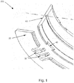
- the flanged bronze bushing 200 of the prior art comprises an axial bearing 20, provided with resilient protrusions 30 and a slide bearing 10, provided with recesses 40 for receiving the resilient protrusions 30.
- the final configuration of the flanged bronze bushing 200 is achieved by mounting the axial bearing 200 on the slide bearing 10. Such a mounting takes place due to the elastic deformation of the protrusions 30 for passing through the recess 40 trapeze and then the protrusions 30 are released, so that the will return to the original non-deformed state, fitting into the recesses 40 and enabling the dismounting thereof.
- This mounting is only possible because the protrusions 30 have such a characteristic that enable them to undergo a stress and return to their initial position, that is, allow them to undergo resilient or elastic deformation, known also as spring effect.
- the object of the present invention tends to solve the problem of resistance to the axial stresses caused by movement of the crankshaft, by means of a flanged bronze bushing 100 provided with a type of fixation in which the protrusions of the axial bearing are deformed during the mounting and do not return to the initial position, that is, taking on a new position, the final position, after they are mounted on the slide bearing.
- the difference between the initial position and the final position is a plastic deformation ⁇ X, which may range from 0.1 to 2.0mm and preferably from 0.1 to 1.0mm.
- Figure 8 shows a plastic deformation ⁇ X of the protrusions 3 by a value of about 0.14mm.
- Figure 2 illustrates one first possible embodiment of the flanged bronze bushing 100 of the present invention, which comprises basically a slide bearing 1 and an axial bearing 2. This figure has a position before the mounting, that is, before the deformable protrusions 3 are inserted into the fixation recess 4.
- the slide bearing 1 has three recesses on each side, arranged in its side regions 6 or thickness, wherein two recesses are inclined 4 and one recess being fix 4' on each side.
- the fixed recess 4' has a shape resembling an inclined square (with inclined side walls), each of them being provided with two inclined side walls, one of the walls having an angle between it and the base ranging from 100° to 170°, preferably 135°, and an angle between the other side wall and the base ranging from 15° to 60°, preferably 45°.
- the axial bearing 2 has deformable fixation protrusions 3. formed by eliminating material around it, apart from the base, which maintains it as part of the axial bearing 2.
- the protrusions 3 are nothing else than the think elements that resemble a finger, the geometry of which is intended to guarantee their plasticity as a function of the materials employed.
- the adjacent spaces 5 are regions where the protrusions 3 are deformed by a measure defined in the design of the piece, so as to flow within the flow limits of the materials, without reaching the break limit of the materials employed, thus taking on a new position.
- the adjacent space 5 will also serve for withdrawal of the axial bearing 2 at a moment of maintenance.
- the deformation for mounting the deformable protrusions 3 into the space 5 is effected by an external force F, as shown in Figure 3 .
- Figure 3 illustrates a detail of one of the inclined recesses 4 provided with two side walls, one of them having smaller angles ranging from 15° to 60° and that serve as stops to catch the deformable protrusions 3 of the axial bearing 2, and the other wall having larger angles ranging from 100° to 170° and that serve aid the deformable protrusions 3 in undergoing plastic deformation, taking on a different position as compared with the position before the mounting.
- the configuration of the two walls, together with the surfaces 10 cause the deformable protrusions 3 to be caught by the stops 9.
- the recesses 4 have the function of preventing release of the axial bearing 2 and of the slide bearing 1 in directions X (rotation), Y (axial) and Z (radial). The prevention takes place due to the form of the stop 9, which has an angle suitable for this function.
- the angle has a geometry cooperating with that of the surface 10, which is at the end of the deformable fixation protrusions 3.
- the recesses 4 and the deformable protrusions 3 match, they cooperate with each other, causing the axial bearing 2 to engage with the slide bearing 1, thus preventing them from detaching from each other.
- the prevention takes place due to the form of the stop 9, which as an angle suitable for this function.
- the angle has a geometry cooperating with that of the surface 10, which is at the end of the deformable fixation protrusions 3, as shown in figure 4 .
- Figure 5 illustrates a flanged bronze bushing 100, prior to mounting, but the latter has at least one axial bearing 2, comprising at least four deformable protrusions 3, grouped in two sets and still a slide bearing 1 having at least four inclined recesses 4, also grouped ion two sets, provided with stops 9 and still at least two fixed recesses 4', one on each side 6 of the slide bearing 1.
- the inclined recesses 4 may have, for this embodiment, the shape of a trapeze, and ion the central part of its larger base there is a trapezoidal protrusion 13, which serves as sliding part of the deformable protrusions 3 during the mounting process.
- Figure 7 illustrates the detail "B" shown in figure 6 , with the protrusions 3 already deformed and in the final position 12, this position being different from the initial position 11, prior to mounting.
- the great advantage of this invention is to promote the axial mounting without introduction of residual stresses, which are harmful to the life, fatigue, associated to the processes of soldering or stamping material, thus facilitating the manufacture process and reducing the mounting cost.
- the flanged bronze bushing 100 presents a solution that facilitates the process of manufacturing the slide bearing, with manufacture different from the pieces involved, separately and joined at the end of the two processes in a third possible place.
- the present invention enables the maintenance of the axial bearing 2, since the dismounting and mounting thereof do not cause damage to any of the parts, making the product more advantageous for the final user.
Description
- The present invention relates to a flanged bronze bushing used on internal combustion engines, provided with a sliding bearing coupled to an axial bearing by fixation means that undergo plastic deformation.
- A flanged bearing according to the preamble of
claim 1 is known fromWO 93/17250 A - The possibility of mounting different materials on the slide bearing and on the axial bearing facilitates its application and prolongs the useful life of the assembly. The use of this type of product is influenced by the convictions of the companies that manufacture engines, which can opt for thrust washers, purely axial bearings, totally separated from the slide bearings by bronze bushings with rigid flange, of a single piece, and still by bronze bushings with mounted flange, with flange fixed to the bronze bushing or flexible wooden bushing, whereby one obtains the benefits of adapting the deformations, widening and mounting, as well as the typical vibrations of internal combustion engines.
- Besides, in order to guarantee the fixation of the rest washer to the bronze bushing, it is necessary to restrict it to three directions, while keeping it flexible, free from rigid links, enabling it to accommodate to the distortions and vibrations that are characteristic of the machines. The first restriction, the rotational one, bears the stresses generated by friction between the rest disk of the crankshaft and the slide surface of the axial bearing, friction torque. The second restriction, the radial one, prevents the flange from detaching totally and falling onto the driving axle. The third restriction is axial and bears the vibration stresses of the driving axle. All these restrictions should guarantee that the flange will not detach during transportation until the assembling of the machine, or during the useful life thereof.
- Various types of fixation were proposed, such as welding, gluing, crushing and resilient fixation. Due to the high manufacture cost resulting from minor geometries and inadequate processes, they have become prohibitive for manufacture. The assembling process by permanent deformation via geometry of the bronze bushing does not require special mounting devices, only the axial mounting force which per se deforms the fixing element in a housing with cooperating geometry, which facilitates the productive process with cost reduction.
- A few examples of the prior art that can be cited are described in the patent documents cited hereinafter.
- Patent document
US4076342 relates to a flange that has, in its internal diameter, a thinner section that is received in a channel in the back of the bronze bearing, on the steal side, guaranteeing retention in the axial direction. The fixation device has two protrusions located at the flange ends and two recesses that are made in the bronze bearing as well. With radial mounting, the bronze bearing deforms and enables the recesses at the ends to receive the flange protrusions, thus fitting into the channel the thin flange section. - Patent document
US4533261 relates to the mounting of the flange in a direction radial to the bronze bushing and the mounting process is an interaction of the rigidity of the bronze bushing with that of the flange. The flange has two spaced-apart protrusions close to the ends, provided with convex prisms, which are responsible for fixing the parts, under cooperation of the recesses in the form of a hook on the bronze bushing. The mounting if of the click-type, working with the two elements bronze bushing and flange, in the elastic phase, since if one presses the flange protrusions exactly onto the recesses on the bronze bushing, both flange and bronze bushing give way and enable the protrusions to fit into the recesses. - Patent document
GB2210113 - Patent document
GB2225392 - Patent document
GB 2225393 GB2225392 - Patent document
GB2241752 - Patent document
US5114246 relates to a solution in which the flange is mounted axially on the bronze bushing. The thrust washer is mounted on the bronze bushing through cooperation between the protrusions and the recesses on the bronze bushing. After insertion of the protrusions into the recesses, they are crushed so as to fixe the flange. - Patent document
EP0515657 relates to a solution in which the fixation of the flange to the bronze bushing is carried out by plastic deformation of one of the fixation protrusions, the latter goes through the slot located at the side of the bronze bushing in the center of the region of the escape recess of the crankshaft radius, the part of the protrusion that remains exposed in the recess is crushed, which prevents the flange from detaching in radial direction. This design offers great risk to the crankshaft radius and may scratch it, thus damaging the assembly. Prevention of rotational movement of the flange is achieved with non-deformable rigid protrusions, fixed in recesses on the bronze bushing, which can be open or in the form of a slot. - Patent document
DE4041557 relates to a solution of radial mounting by elastic deformation of the bronze bushing, thus enabling the introduction of hook-shaped recesses, which engage with recesses on the bronze bushing. Brazilian Patent documentPI 0703980-8 - For better understanding, the cited patent documents are listed below, according to their mounting characteristics or to the type of fixation.
Table 1- Technical solution for mounting a flange Mounting dirction Type of fixationsolution Patent number Filing date Axial Radial "click"' Elastic Plastic US4533261 JUN, 6, 85 x x x GB2210113 AUG, 2, 88 x x x GB2225392 NOV, 25, 88 x x GB2225393 NOV, 25, 88 x x GB2241752 MAR 2, 90x x US5114246 DEC 2, 90x x DE4041557 DEC 22, 90 x x x EP0515657 DEC 17, 91 x x PI 0703980-8 SEP 4,07x x - As demonstrated above, there are a number of ideas for the solution to flange mounting, many of them with subtleties that depend on fractions of an angle to guarantee fixation or even lowermost tenths of millimeters for the same function.
- In most documents presented, the locking elements presented impair the life of the assembly because they are thin and may break, or they may not even be produced due to the great flexibility of the elements. Other solutions such as welding, and gluing, were also used for fixation, but such solutions make the system extremely rigid, losing the benefit of flexibility of the flange with respect to the bronze bushing.
- However, as can be seen, there is now solution presenting a bronze bushing composed by an axial bearing and a slide bearing, wherein the axial bearing engages with the slide bearing by plastic deformation, without impairing the integrity of the flange-fixing element, since the plastic deformation of the fixing element is made within geometries and dimensions that are feasible in present-day manufacture processes.
- Therefore, it is an objective of the present invention to provide a flanged bronze bushing containing a slide bearing, and it may be a bronze bushing or a bushing that enables one to mount at least one axial bearing in the form of a flange that can be attached, fitted or even mounted, enabling relative movements of plastic fixation claws with respect to each other, which are designated herein as deformable protrusions and are extensions of the inner diameter, having corresponding cooperating geometry recesses on the slide bearing.
- It is a further objective of the present invention to enable the mounting of different materials between the axial bearing and the slide bearing. Thus, one can mount a polymeric flange on a slide bearing of a metallic compound or vice-versa, both having tribologic properties suitable to the application thus contributing to the technological development of the machines.
- The objectives of the present invention are achieved by means of a flanged bronze bushing according to
claim 1. The above-mentioned characteristics, in addition to other features of the present invention, will be better understood through the examples and the detailed description of the attached figures. - The present invention will now be described in greater detail with reference to an embodiment represented in the drawings. The figures show:
-
Figure 1 is an illustration of a flanged bronze bushing of the prior art, provided with resilient fixation means; -
Figure 2 is an illustration of an embodiment of a flanged bronze bushing according to the present invention, prior to association between its parts; -
Figure 3 is an illustration of the protrusions of the axial bearing prior to association to the recess of the slide bearing; -
Figure 4 is an illustration of the detail "A" inFigure 2 , after association between its parts; -
Figure 5 is an illustration of a possible embodiment of the flanged bronze bushing of the present invention, prior to association between its parts; -
Figure 6 is an illustration of the flanged bronze bushing shown infigure 5 , after association between its parts; -
Figure 7 is an illustration of the detail "B" of the bronze bushing illustrated ionfigure 6 ; -
Figure 8 is an illustration of an example of the plastic deformation of mounting of the deformable protrusions. - The present invention relates to a flanged
bronze bushing 100, for use on internal combustion engine, particularly on the crankshaft. Such use is due to the fact that, when the vehicle is in motion or geared, the transmission remains coupled to the motor by means of the clutch, which, in its essence, uses the crankshaft as a support point to promote the uncoupling of the engine from the transmission, which results from stepping on the vehicle clutch, thus enabling gear change. It is at this moment that the crankshaft undergoes a great axial stress, reflecting the stress to the axial bearing, known also as flange. - The flanged bronze bushing 100 of the present invention was invented with a view to enable perfect functioning of moveable parts, minimizing friction and guaranteeing movement with respective the transmission of force.
- However, before describing the flanged
bronze bushing 100 of the present invention, one should distinguish it from the solution presented in the prior art, which represents a flangedbronze bushing 200 capable of bearing said axial movements caused by the crankshaft so as not to detach. - For this purpose and as can be seen in
figure 1 , theflanged bronze bushing 200 of the prior art comprises an axial bearing 20, provided withresilient protrusions 30 and a slide bearing 10, provided withrecesses 40 for receiving theresilient protrusions 30. - The final configuration of the
flanged bronze bushing 200 is achieved by mounting theaxial bearing 200 on theslide bearing 10. Such a mounting takes place due to the elastic deformation of theprotrusions 30 for passing through therecess 40 trapeze and then theprotrusions 30 are released, so that the will return to the original non-deformed state, fitting into therecesses 40 and enabling the dismounting thereof. This mounting is only possible because theprotrusions 30 have such a characteristic that enable them to undergo a stress and return to their initial position, that is, allow them to undergo resilient or elastic deformation, known also as spring effect. - The object of the present invention tends to solve the problem of resistance to the axial stresses caused by movement of the crankshaft, by means of a
flanged bronze bushing 100 provided with a type of fixation in which the protrusions of the axial bearing are deformed during the mounting and do not return to the initial position, that is, taking on a new position, the final position, after they are mounted on the slide bearing. The difference between the initial position and the final position is a plastic deformation ΔX, which may range from 0.1 to 2.0mm and preferably from 0.1 to 1.0mm. As an example,Figure 8 shows a plastic deformation ΔX of theprotrusions 3 by a value of about 0.14mm. -
Figure 2 illustrates one first possible embodiment of theflanged bronze bushing 100 of the present invention, which comprises basically aslide bearing 1 and anaxial bearing 2. This figure has a position before the mounting, that is, before thedeformable protrusions 3 are inserted into thefixation recess 4. - As one can further see in
figure 2 , theslide bearing 1 has three recesses on each side, arranged in itsside regions 6 or thickness, wherein two recesses are inclined 4 and one recess being fix 4' on each side. The fixed recess 4' has a shape resembling an inclined square (with inclined side walls), each of them being provided with two inclined side walls, one of the walls having an angle between it and the base ranging from 100° to 170°, preferably 135°, and an angle between the other side wall and the base ranging from 15° to 60°, preferably 45°. - It is further possible to observe in
figure 2 that theaxial bearing 2 hasdeformable fixation protrusions 3. formed by eliminating material around it, apart from the base, which maintains it as part of theaxial bearing 2. Theprotrusions 3 are nothing else than the think elements that resemble a finger, the geometry of which is intended to guarantee their plasticity as a function of the materials employed. On the other hand, theadjacent spaces 5 are regions where theprotrusions 3 are deformed by a measure defined in the design of the piece, so as to flow within the flow limits of the materials, without reaching the break limit of the materials employed, thus taking on a new position. Theadjacent space 5 will also serve for withdrawal of theaxial bearing 2 at a moment of maintenance. The deformation for mounting thedeformable protrusions 3 into thespace 5 is effected by an external force F, as shown inFigure 3 . - The stresses due to the deformation for mounting, at the base of the
deformable protrusions 3, are minimized by stress-alleviatingrounded surfaces 7, adjacent thedeformable fixation protrusions 3 and that impart plasticity to them, known in the technical literature as being suitable for this purpose. Thedeformable fixation protrusions 3 of theaxial bearing 2, further have, at their ends, ahead of the inner diameter of the bearing, chamfers or surfaces 10 that cooperate with the surfaces formed by the stops 9 of theslide bearing 1 at the time of mounting. Theinclined recess 4, which have stops 9, is shaped like an inclined square, so that thesurfaces 10 at the ends of the twodeformable fixation protrusions 3 will cooperate for fixation thereof, by virtue of the similarity in geometry. The fixation of theaxial bearing 2 in axial direction is guaranteed by the retention ofsurface 10 by the stop 9. -
Figure 3 illustrates a detail of one of theinclined recesses 4 provided with two side walls, one of them having smaller angles ranging from 15° to 60° and that serve as stops to catch thedeformable protrusions 3 of theaxial bearing 2, and the other wall having larger angles ranging from 100° to 170° and that serve aid thedeformable protrusions 3 in undergoing plastic deformation, taking on a different position as compared with the position before the mounting. During the mounting, the configuration of the two walls, together with thesurfaces 10, cause thedeformable protrusions 3 to be caught by the stops 9. - The
recesses 4 have the function of preventing release of theaxial bearing 2 and of theslide bearing 1 in directions X (rotation), Y (axial) and Z (radial). The prevention takes place due to the form of the stop 9, which has an angle suitable for this function. The angle has a geometry cooperating with that of thesurface 10, which is at the end of thedeformable fixation protrusions 3. - Once the
recesses 4 and thedeformable protrusions 3 match, they cooperate with each other, causing theaxial bearing 2 to engage with theslide bearing 1, thus preventing them from detaching from each other. The prevention takes place due to the form of the stop 9, which as an angle suitable for this function. The angle has a geometry cooperating with that of thesurface 10, which is at the end of thedeformable fixation protrusions 3, as shown infigure 4 . - It should be reminded that the fixation of the
axial bearing 2 and of theslide bearing 1 takes place in the three main direction: axial, radial, rotational. The axial fixation if promoted by the stops 9 and by the geometric cooperation of thechamfer 10 and still by the fixed recess 4' and by thefix protrusion 8. In the radial direction, it takes place by distribution of theinclined recesses 4 anddeformable protrusions 3 along the 180 degrees of the bronze bushing and of the slide bearing, respectively, so that the stops 9 will be in divergence with the releasing movement. In the rotational direction, it is prevented by the section resistant to shearing force of theprotrusion 3 and to crushing by the cooperating geometries of thechamfer 10 and of the stop 9. It should be noted that for each slide bearing 1 twoaxial bearings 2 are mounted, one in eachside region 6. -
Figure 5 , in turn, illustrates aflanged bronze bushing 100, prior to mounting, but the latter has at least oneaxial bearing 2, comprising at least fourdeformable protrusions 3, grouped in two sets and still aslide bearing 1 having at least fourinclined recesses 4, also grouped ion two sets, provided with stops 9 and still at least two fixed recesses 4', one on eachside 6 of theslide bearing 1. Theinclined recesses 4 may have, for this embodiment, the shape of a trapeze, and ion the central part of its larger base there is atrapezoidal protrusion 13, which serves as sliding part of thedeformable protrusions 3 during the mounting process. -
Figure 6 illustrates aflanged bronze bushing 100 after mounting, wherein, as described for the first embodiment, thedeformable protrusions 3, upon receiving a force F (as illustrated infigure 3 ), are capable of deforming, sliding over the inclined walls of theinclined recesses 4 and fixing with the stops 9, thus causing theaxial bearing 2 to fix to theslide bearing 1, compulsorily in the three main directions: axial, radial, rotational. After deformation, the deformable protrusions exhibit plastic deformation ΔX ranging from 0.1 to 1.0mm (an example thereof can be observed infigure 8 ). -
Figure 7 illustrates the detail "B" shown infigure 6 , with theprotrusions 3 already deformed and in the final position 12, this position being different from the initial position 11, prior to mounting. - It should be noted that both the
slide bearing 1 and theaxial bearing 2 may be made from the same material, from different materials or still may have various layers of different materials. As for example the following materials: plastic resin, epoxy resin, material containing fluoride or fluoropolymer. - The great advantage of this invention is to promote the axial mounting without introduction of residual stresses, which are harmful to the life, fatigue, associated to the processes of soldering or stamping material, thus facilitating the manufacture process and reducing the mounting cost.
- The perfect adjustment between the stops 9 and the
surfaces 10 takes place due to the similarity thereof, cooperating so as to prevent release of theflange 2 from thebronze bushing 1, in directions X, Y, and Z. - The sequence of mounting the
axial bearing 2 with theslide bearing 1 is described hereinafter, following the these steps: - (I) The
axial bearings 2 are in the free position and with one group offixation protrusions 3 with initial spacing of 3.0mm (as shown infigure 8 ); - (II) The
deformable protrusions 3 undergo the external force F (seefigure 3 ), sliding into theinclined recesses 4, so as to take on the final position 12; - (III) The
inclined recesses 4 with the stops 9 having cooperating geometry receive theplastic protrusions 3, already deformed; - (IV) The
axial bearings 2 mounted in theinclined recesses 4 and theplastic protrusions 3 reach the final position 12, undergoing a plastic deformation ΔX ranging from 0.1 to 1.0mm due to the plasticity property. - This, it is clear that the
flanged bronze bushing 100 presents a solution that facilitates the process of manufacturing the slide bearing, with manufacture different from the pieces involved, separately and joined at the end of the two processes in a third possible place. Thus, one provides flexibility in the choice of processes, materials and manufacture places, which results in better cost/benefit and greater social return. The present invention enables the maintenance of theaxial bearing 2, since the dismounting and mounting thereof do not cause damage to any of the parts, making the product more advantageous for the final user.
Claims (3)
- A flanged bronze bushing, comprising:- one radial slide bearing (1) and two axial slide bearings (2) in the form of a flange,- wherein the radial slide bearing (1) comprises at least inclined (4) and fixed (4') recesses arranged in the side region (6), and wherein the axial bearing (2) comprises at least one deformable protrusion (3) arranged in a first position (12), a rigid protrusion (8) and a cooperating surface (10) arranged on the deformable protrusion,- wherein the axial bearing (2) is capable of being integrated with the radial slide bearing (1) through association of the cooperating surface (10) of the deformable protrusion (3) with the inclined recess (4), the deformable protrusion (3) taking on a second position (12), which exhibits plastic deformation (ΔX) with respect to the first position (11); and through simultaneous association of the rigid protrusion (8) with the fixed recess (4'),characterized in that- the sliding bearing (1) comprises in each side region (6) two inclined recesses (4) and one fixed recess (4'),- the inclined recesses (4) are provided with two side walls, one of the side walls having angles ranging from 15° to 60° and the other wall having angles ranging from 100° to 170°,- the fixed recess (4') is provided with two inclined side walls, one of the side walls having an angle between it and the base ranging from 15° to 60° and the other having an angle between it and the base ranging from 100° to 170°.
- A flanged bronze bushing according to claim 1,
characterized in that
one of the side walls from the fixed recess (4) having an angle between it and the base of 45° and the other wall having an angle between it and the base of 135°. - A flanged bronze bushing according to claim 1,
characterized in that
the deformable protrusions (3) comprise adjacent to them, stress-alleviating rounded surfaces (7).
Applications Claiming Priority (2)
| Application Number | Priority Date | Filing Date | Title |
|---|---|---|---|
| BRPI1100941-1A BRPI1100941A2 (en) | 2011-03-25 | 2011-03-25 | flanged bearing |
| PCT/BR2012/000074 WO2012129624A1 (en) | 2011-03-25 | 2012-03-23 | Flanged bushing |
Publications (2)
| Publication Number | Publication Date |
|---|---|
| EP2690295A1 EP2690295A1 (en) | 2014-01-29 |
| EP2690295B1 true EP2690295B1 (en) | 2017-10-18 |
Family
ID=46051632
Family Applications (1)
| Application Number | Title | Priority Date | Filing Date |
|---|---|---|---|
| EP12719922.2A Not-in-force EP2690295B1 (en) | 2011-03-25 | 2012-03-23 | Flanged bronze bearing |
Country Status (6)
| Country | Link |
|---|---|
| US (1) | US20140177987A1 (en) |
| EP (1) | EP2690295B1 (en) |
| JP (1) | JP2014509722A (en) |
| CN (1) | CN103797253A (en) |
| BR (1) | BRPI1100941A2 (en) |
| WO (1) | WO2012129624A1 (en) |
Families Citing this family (6)
| Publication number | Priority date | Publication date | Assignee | Title |
|---|---|---|---|---|
| JP2016161013A (en) * | 2015-02-27 | 2016-09-05 | 大豊工業株式会社 | Slide bearing |
| US9879718B2 (en) * | 2015-06-19 | 2018-01-30 | Taiho Kogyo Co., Ltd. | Sliding bearing and method for manufacturing sliding bearing |
| JP6495759B2 (en) * | 2015-06-19 | 2019-04-03 | 大豊工業株式会社 | Plain bearing |
| GB2541423B (en) * | 2015-08-19 | 2021-05-05 | Mahle Int Gmbh | Sliding element comprising at least one coupling element |
| DE102016114132A1 (en) | 2016-07-29 | 2018-02-01 | Ks Gleitlager Gmbh | Built half shell-shaped flange bearing shell |
| CA3069822C (en) * | 2017-07-14 | 2023-03-21 | Saint-Gobain Performance Plastics Pampus Gmbh | Clip, clip assembly, and method of making and using the same |
Family Cites Families (15)
| Publication number | Priority date | Publication date | Assignee | Title |
|---|---|---|---|---|
| GB1483011A (en) | 1975-02-05 | 1977-08-17 | Glacier Metal Co Ltd | Plain bearing |
| IT1175166B (en) | 1983-02-03 | 1987-07-01 | Clevite Srl | FLANGED HALF BEARING FOR ENGINEERING APPLICATIONS |
| GB8721841D0 (en) | 1987-09-17 | 1987-10-21 | Coussinets Ste Indle | Bearings |
| GB8827606D0 (en) | 1988-11-25 | 1988-12-29 | Vandervell Ltd | Bearings |
| GB8827607D0 (en) | 1988-11-25 | 1988-12-29 | Vandervell Ltd | Bearings |
| JP2660039B2 (en) * | 1989-01-31 | 1997-10-08 | 大同メタル工業株式会社 | Assembled flange bearing |
| DE3933667C1 (en) * | 1989-10-09 | 1991-01-24 | Glyco-Metall-Werke Daelen & Loos Gmbh, 6200 Wiesbaden, De | Combined radial and axial bearing bush - includes split bearing shells and two detachable thrust ring couplings |
| GB9004716D0 (en) | 1990-03-02 | 1990-04-25 | Glacier Metal Co Ltd | Bearings |
| US5114246A (en) | 1990-12-03 | 1992-05-19 | Jpi Transportation Products, Inc. | Floating flange half bearing |
| DE4041557C2 (en) | 1990-12-22 | 1996-08-22 | Glyco Metall Werke | Combined radial-axial plain bearing |
| DE4140277C2 (en) * | 1990-12-22 | 1993-12-23 | Glyco Metall Werke | Composite radial-axial plain bearing and method for its production |
| DE4303855C1 (en) * | 1992-02-19 | 1994-06-23 | Glyco Metall Werke | Compound radial-axial plain bearing |
| EP1682783A4 (en) * | 2003-11-13 | 2009-06-10 | Federal Mogul Corp | Thrust washer and method of manufacture |
| BRPI0703980B1 (en) * | 2007-09-04 | 2019-09-24 | Mahle Metal Leve S/A | FLANGE BRONZINA |
| DE102009015370A1 (en) * | 2009-03-27 | 2010-10-28 | Ks Gleitlager Gmbh | Built-flange shell with half-shell-shaped radial bearing part and with at least one disc-shaped thrust bearing |
-
2011
- 2011-03-25 BR BRPI1100941-1A patent/BRPI1100941A2/en not_active Application Discontinuation
-
2012
- 2012-03-23 CN CN201280020895.4A patent/CN103797253A/en active Pending
- 2012-03-23 WO PCT/BR2012/000074 patent/WO2012129624A1/en active Application Filing
- 2012-03-23 EP EP12719922.2A patent/EP2690295B1/en not_active Not-in-force
- 2012-03-23 JP JP2014501368A patent/JP2014509722A/en active Pending
- 2012-03-23 US US14/007,326 patent/US20140177987A1/en not_active Abandoned
Non-Patent Citations (1)
| Title |
|---|
| None * |
Also Published As
| Publication number | Publication date |
|---|---|
| CN103797253A (en) | 2014-05-14 |
| WO2012129624A1 (en) | 2012-10-04 |
| JP2014509722A (en) | 2014-04-21 |
| EP2690295A1 (en) | 2014-01-29 |
| BRPI1100941A2 (en) | 2013-06-11 |
| US20140177987A1 (en) | 2014-06-26 |
Similar Documents
| Publication | Publication Date | Title |
|---|---|---|
| EP2690295B1 (en) | Flanged bronze bearing | |
| EP2195545B1 (en) | Flanged bushing | |
| JP2015068344A (en) | Cam follower, injection pump with cam follower, valve actuator, and manufacturing method thereof | |
| GB2496192A (en) | A flanged half-bearing | |
| DE102012204598A1 (en) | Crankshaft bearing for an internal combustion engine | |
| CN105508545A (en) | Rotating device with combined transmission shaft and combined transmission shaft thereof | |
| US20170207671A1 (en) | Rotor for an electric motor | |
| AU2017225044A1 (en) | Rotary electric rotor and method of manufacturing rotary electric rotor | |
| EP3088755B1 (en) | A powertrain mechanism with drive plate | |
| EP2499387A1 (en) | Clutch assembly | |
| US3935934A (en) | Releasable axial clutch | |
| DE102010010735A1 (en) | Clutch release sleeve for power transmission of clutch coupling box on turning cup spring, has sealing element sealing interior storage space between rings and secured at one of rings, where sealing element is made of plastic | |
| US9599171B2 (en) | One-way clutch and sheet feeding roller | |
| EP1544487B1 (en) | Rotation transmission member and method for assembling a rotation transmission member | |
| EP3524854B1 (en) | Scissor gear assembly and internal combustion engine provided with the scissor gear assembly | |
| EP1950438B1 (en) | Transmission system for a motor vehicle | |
| DE102016218975A1 (en) | Hub assembly for a shaft-hub connection | |
| WO2014154212A1 (en) | Dual mass flywheel with a sliding mounting, and method for the installation thereof | |
| US20190170236A1 (en) | Gears and gear combinations | |
| CN218236022U (en) | Shearing gear, transmission system, engine and vehicle | |
| EP2251572B1 (en) | Seal arrangement | |
| CN211599463U (en) | Front rubber vibration reduction gear integrated mechanism, engine and automobile | |
| JP2007232162A (en) | Idle gear support structure | |
| JP5913855B2 (en) | Combination of camshaft and auxiliary equipment | |
| CN114746627B (en) | Roller tappet |
Legal Events
| Date | Code | Title | Description |
|---|---|---|---|
| PUAI | Public reference made under article 153(3) epc to a published international application that has entered the european phase |
Free format text: ORIGINAL CODE: 0009012 |
|
| 17P | Request for examination filed |
Effective date: 20131021 |
|
| AK | Designated contracting states |
Kind code of ref document: A1 Designated state(s): AL AT BE BG CH CY CZ DE DK EE ES FI FR GB GR HR HU IE IS IT LI LT LU LV MC MK MT NL NO PL PT RO RS SE SI SK SM TR |
|
| DAX | Request for extension of the european patent (deleted) | ||
| 17Q | First examination report despatched |
Effective date: 20161011 |
|
| GRAP | Despatch of communication of intention to grant a patent |
Free format text: ORIGINAL CODE: EPIDOSNIGR1 |
|
| RIC1 | Information provided on ipc code assigned before grant |
Ipc: F16C 33/04 20060101ALI20170516BHEP Ipc: F16C 17/10 20060101AFI20170516BHEP Ipc: F16C 43/02 20060101ALI20170516BHEP |
|
| INTG | Intention to grant announced |
Effective date: 20170607 |
|
| GRAS | Grant fee paid |
Free format text: ORIGINAL CODE: EPIDOSNIGR3 |
|
| GRAA | (expected) grant |
Free format text: ORIGINAL CODE: 0009210 |
|
| AK | Designated contracting states |
Kind code of ref document: B1 Designated state(s): AL AT BE BG CH CY CZ DE DK EE ES FI FR GB GR HR HU IE IS IT LI LT LU LV MC MK MT NL NO PL PT RO RS SE SI SK SM TR |
|
| REG | Reference to a national code |
Ref country code: GB Ref legal event code: FG4D |
|
| REG | Reference to a national code |
Ref country code: CH Ref legal event code: EP |
|
| REG | Reference to a national code |
Ref country code: AT Ref legal event code: REF Ref document number: 938209 Country of ref document: AT Kind code of ref document: T Effective date: 20171115 Ref country code: IE Ref legal event code: FG4D |
|
| REG | Reference to a national code |
Ref country code: DE Ref legal event code: R096 Ref document number: 602012038642 Country of ref document: DE |
|
| REG | Reference to a national code |
Ref country code: NL Ref legal event code: MP Effective date: 20171018 |
|
| REG | Reference to a national code |
Ref country code: LT Ref legal event code: MG4D |
|
| REG | Reference to a national code |
Ref country code: AT Ref legal event code: MK05 Ref document number: 938209 Country of ref document: AT Kind code of ref document: T Effective date: 20171018 |
|
| PG25 | Lapsed in a contracting state [announced via postgrant information from national office to epo] |
Ref country code: NL Free format text: LAPSE BECAUSE OF FAILURE TO SUBMIT A TRANSLATION OF THE DESCRIPTION OR TO PAY THE FEE WITHIN THE PRESCRIBED TIME-LIMIT Effective date: 20171018 |
|
| PG25 | Lapsed in a contracting state [announced via postgrant information from national office to epo] |
Ref country code: NO Free format text: LAPSE BECAUSE OF FAILURE TO SUBMIT A TRANSLATION OF THE DESCRIPTION OR TO PAY THE FEE WITHIN THE PRESCRIBED TIME-LIMIT Effective date: 20180118 Ref country code: ES Free format text: LAPSE BECAUSE OF FAILURE TO SUBMIT A TRANSLATION OF THE DESCRIPTION OR TO PAY THE FEE WITHIN THE PRESCRIBED TIME-LIMIT Effective date: 20171018 Ref country code: LT Free format text: LAPSE BECAUSE OF FAILURE TO SUBMIT A TRANSLATION OF THE DESCRIPTION OR TO PAY THE FEE WITHIN THE PRESCRIBED TIME-LIMIT Effective date: 20171018 Ref country code: SE Free format text: LAPSE BECAUSE OF FAILURE TO SUBMIT A TRANSLATION OF THE DESCRIPTION OR TO PAY THE FEE WITHIN THE PRESCRIBED TIME-LIMIT Effective date: 20171018 Ref country code: FI Free format text: LAPSE BECAUSE OF FAILURE TO SUBMIT A TRANSLATION OF THE DESCRIPTION OR TO PAY THE FEE WITHIN THE PRESCRIBED TIME-LIMIT Effective date: 20171018 |
|
| PG25 | Lapsed in a contracting state [announced via postgrant information from national office to epo] |
Ref country code: IS Free format text: LAPSE BECAUSE OF FAILURE TO SUBMIT A TRANSLATION OF THE DESCRIPTION OR TO PAY THE FEE WITHIN THE PRESCRIBED TIME-LIMIT Effective date: 20180218 Ref country code: AT Free format text: LAPSE BECAUSE OF FAILURE TO SUBMIT A TRANSLATION OF THE DESCRIPTION OR TO PAY THE FEE WITHIN THE PRESCRIBED TIME-LIMIT Effective date: 20171018 Ref country code: LV Free format text: LAPSE BECAUSE OF FAILURE TO SUBMIT A TRANSLATION OF THE DESCRIPTION OR TO PAY THE FEE WITHIN THE PRESCRIBED TIME-LIMIT Effective date: 20171018 Ref country code: HR Free format text: LAPSE BECAUSE OF FAILURE TO SUBMIT A TRANSLATION OF THE DESCRIPTION OR TO PAY THE FEE WITHIN THE PRESCRIBED TIME-LIMIT Effective date: 20171018 Ref country code: GR Free format text: LAPSE BECAUSE OF FAILURE TO SUBMIT A TRANSLATION OF THE DESCRIPTION OR TO PAY THE FEE WITHIN THE PRESCRIBED TIME-LIMIT Effective date: 20180119 Ref country code: RS Free format text: LAPSE BECAUSE OF FAILURE TO SUBMIT A TRANSLATION OF THE DESCRIPTION OR TO PAY THE FEE WITHIN THE PRESCRIBED TIME-LIMIT Effective date: 20171018 Ref country code: BG Free format text: LAPSE BECAUSE OF FAILURE TO SUBMIT A TRANSLATION OF THE DESCRIPTION OR TO PAY THE FEE WITHIN THE PRESCRIBED TIME-LIMIT Effective date: 20180118 |
|
| REG | Reference to a national code |
Ref country code: DE Ref legal event code: R097 Ref document number: 602012038642 Country of ref document: DE |
|
| PG25 | Lapsed in a contracting state [announced via postgrant information from national office to epo] |
Ref country code: DK Free format text: LAPSE BECAUSE OF FAILURE TO SUBMIT A TRANSLATION OF THE DESCRIPTION OR TO PAY THE FEE WITHIN THE PRESCRIBED TIME-LIMIT Effective date: 20171018 Ref country code: EE Free format text: LAPSE BECAUSE OF FAILURE TO SUBMIT A TRANSLATION OF THE DESCRIPTION OR TO PAY THE FEE WITHIN THE PRESCRIBED TIME-LIMIT Effective date: 20171018 Ref country code: SK Free format text: LAPSE BECAUSE OF FAILURE TO SUBMIT A TRANSLATION OF THE DESCRIPTION OR TO PAY THE FEE WITHIN THE PRESCRIBED TIME-LIMIT Effective date: 20171018 Ref country code: CZ Free format text: LAPSE BECAUSE OF FAILURE TO SUBMIT A TRANSLATION OF THE DESCRIPTION OR TO PAY THE FEE WITHIN THE PRESCRIBED TIME-LIMIT Effective date: 20171018 |
|
| PLBE | No opposition filed within time limit |
Free format text: ORIGINAL CODE: 0009261 |
|
| STAA | Information on the status of an ep patent application or granted ep patent |
Free format text: STATUS: NO OPPOSITION FILED WITHIN TIME LIMIT |
|
| PG25 | Lapsed in a contracting state [announced via postgrant information from national office to epo] |
Ref country code: RO Free format text: LAPSE BECAUSE OF FAILURE TO SUBMIT A TRANSLATION OF THE DESCRIPTION OR TO PAY THE FEE WITHIN THE PRESCRIBED TIME-LIMIT Effective date: 20171018 Ref country code: IT Free format text: LAPSE BECAUSE OF FAILURE TO SUBMIT A TRANSLATION OF THE DESCRIPTION OR TO PAY THE FEE WITHIN THE PRESCRIBED TIME-LIMIT Effective date: 20171018 Ref country code: SM Free format text: LAPSE BECAUSE OF FAILURE TO SUBMIT A TRANSLATION OF THE DESCRIPTION OR TO PAY THE FEE WITHIN THE PRESCRIBED TIME-LIMIT Effective date: 20171018 Ref country code: PL Free format text: LAPSE BECAUSE OF FAILURE TO SUBMIT A TRANSLATION OF THE DESCRIPTION OR TO PAY THE FEE WITHIN THE PRESCRIBED TIME-LIMIT Effective date: 20171018 |
|
| 26N | No opposition filed |
Effective date: 20180719 |
|
| REG | Reference to a national code |
Ref country code: CH Ref legal event code: PL |
|
| GBPC | Gb: european patent ceased through non-payment of renewal fee |
Effective date: 20180323 |
|
| PG25 | Lapsed in a contracting state [announced via postgrant information from national office to epo] |
Ref country code: MC Free format text: LAPSE BECAUSE OF FAILURE TO SUBMIT A TRANSLATION OF THE DESCRIPTION OR TO PAY THE FEE WITHIN THE PRESCRIBED TIME-LIMIT Effective date: 20171018 Ref country code: SI Free format text: LAPSE BECAUSE OF FAILURE TO SUBMIT A TRANSLATION OF THE DESCRIPTION OR TO PAY THE FEE WITHIN THE PRESCRIBED TIME-LIMIT Effective date: 20171018 |
|
| REG | Reference to a national code |
Ref country code: BE Ref legal event code: MM Effective date: 20180331 |
|
| REG | Reference to a national code |
Ref country code: IE Ref legal event code: MM4A |
|
| PG25 | Lapsed in a contracting state [announced via postgrant information from national office to epo] |
Ref country code: LU Free format text: LAPSE BECAUSE OF NON-PAYMENT OF DUE FEES Effective date: 20180323 |
|
| PG25 | Lapsed in a contracting state [announced via postgrant information from national office to epo] |
Ref country code: IE Free format text: LAPSE BECAUSE OF NON-PAYMENT OF DUE FEES Effective date: 20180323 |
|
| PG25 | Lapsed in a contracting state [announced via postgrant information from national office to epo] |
Ref country code: GB Free format text: LAPSE BECAUSE OF NON-PAYMENT OF DUE FEES Effective date: 20180323 Ref country code: LI Free format text: LAPSE BECAUSE OF NON-PAYMENT OF DUE FEES Effective date: 20180331 Ref country code: CH Free format text: LAPSE BECAUSE OF NON-PAYMENT OF DUE FEES Effective date: 20180331 Ref country code: BE Free format text: LAPSE BECAUSE OF NON-PAYMENT OF DUE FEES Effective date: 20180331 |
|
| PG25 | Lapsed in a contracting state [announced via postgrant information from national office to epo] |
Ref country code: FR Free format text: LAPSE BECAUSE OF NON-PAYMENT OF DUE FEES Effective date: 20180331 |
|
| PG25 | Lapsed in a contracting state [announced via postgrant information from national office to epo] |
Ref country code: MT Free format text: LAPSE BECAUSE OF NON-PAYMENT OF DUE FEES Effective date: 20180323 |
|
| PG25 | Lapsed in a contracting state [announced via postgrant information from national office to epo] |
Ref country code: TR Free format text: LAPSE BECAUSE OF FAILURE TO SUBMIT A TRANSLATION OF THE DESCRIPTION OR TO PAY THE FEE WITHIN THE PRESCRIBED TIME-LIMIT Effective date: 20171018 |
|
| PG25 | Lapsed in a contracting state [announced via postgrant information from national office to epo] |
Ref country code: PT Free format text: LAPSE BECAUSE OF FAILURE TO SUBMIT A TRANSLATION OF THE DESCRIPTION OR TO PAY THE FEE WITHIN THE PRESCRIBED TIME-LIMIT Effective date: 20171018 Ref country code: HU Free format text: LAPSE BECAUSE OF FAILURE TO SUBMIT A TRANSLATION OF THE DESCRIPTION OR TO PAY THE FEE WITHIN THE PRESCRIBED TIME-LIMIT; INVALID AB INITIO Effective date: 20120323 |
|
| PG25 | Lapsed in a contracting state [announced via postgrant information from national office to epo] |
Ref country code: MK Free format text: LAPSE BECAUSE OF NON-PAYMENT OF DUE FEES Effective date: 20171018 Ref country code: CY Free format text: LAPSE BECAUSE OF FAILURE TO SUBMIT A TRANSLATION OF THE DESCRIPTION OR TO PAY THE FEE WITHIN THE PRESCRIBED TIME-LIMIT Effective date: 20171018 |
|
| PG25 | Lapsed in a contracting state [announced via postgrant information from national office to epo] |
Ref country code: AL Free format text: LAPSE BECAUSE OF FAILURE TO SUBMIT A TRANSLATION OF THE DESCRIPTION OR TO PAY THE FEE WITHIN THE PRESCRIBED TIME-LIMIT Effective date: 20171018 |
|
| PGFP | Annual fee paid to national office [announced via postgrant information from national office to epo] |
Ref country code: DE Payment date: 20210427 Year of fee payment: 10 |
|
| REG | Reference to a national code |
Ref country code: DE Ref legal event code: R119 Ref document number: 602012038642 Country of ref document: DE |
|
| PG25 | Lapsed in a contracting state [announced via postgrant information from national office to epo] |
Ref country code: DE Free format text: LAPSE BECAUSE OF NON-PAYMENT OF DUE FEES Effective date: 20221001 |