EP2690038A1 - Palettier-, Stapel- und/oder Handhabungsvorrichtung - Google Patents
Palettier-, Stapel- und/oder Handhabungsvorrichtung Download PDFInfo
- Publication number
- EP2690038A1 EP2690038A1 EP13174650.5A EP13174650A EP2690038A1 EP 2690038 A1 EP2690038 A1 EP 2690038A1 EP 13174650 A EP13174650 A EP 13174650A EP 2690038 A1 EP2690038 A1 EP 2690038A1
- Authority
- EP
- European Patent Office
- Prior art keywords
- hollow container
- counterweight
- palletizing
- palletizing device
- bed
- Prior art date
- Legal status (The legal status is an assumption and is not a legal conclusion. Google has not performed a legal analysis and makes no representation as to the accuracy of the status listed.)
- Granted
Links
Images


Classifications
-
- B—PERFORMING OPERATIONS; TRANSPORTING
- B65—CONVEYING; PACKING; STORING; HANDLING THIN OR FILAMENTARY MATERIAL
- B65G—TRANSPORT OR STORAGE DEVICES, e.g. CONVEYORS FOR LOADING OR TIPPING, SHOP CONVEYOR SYSTEMS OR PNEUMATIC TUBE CONVEYORS
- B65G57/00—Stacking of articles
-
- B—PERFORMING OPERATIONS; TRANSPORTING
- B65—CONVEYING; PACKING; STORING; HANDLING THIN OR FILAMENTARY MATERIAL
- B65G—TRANSPORT OR STORAGE DEVICES, e.g. CONVEYORS FOR LOADING OR TIPPING, SHOP CONVEYOR SYSTEMS OR PNEUMATIC TUBE CONVEYORS
- B65G59/00—De-stacking of articles
Definitions
- the present invention relates to a palletizing, stacking and / or handling device having the features of independent claim 1.
- lifting and handling devices for lifting or transferring loads.
- many of the numerous known lifting or handling devices for lifting or transfer of loads is to be lifted or reacted load outside the center of gravity of the device, so depending on the lever ratios occurring during operation counterweights are required to improper load conditions or even tipping the To prevent lifting or handling devices.
- boom cranes need a counterweight for safe operation, which is hinged to a horizontal arm opposite the rear support arm and prevents an unacceptably high bending load acting on the mast.
- a jib crane for lifting and moving loads on construction sites with a variable counterweight is from the KR 2011 000 44 77 U known.
- the counterweight suspended from a rear boom is constituted by a liquid tank coupled to a reservoir by a pump. By pumping the liquid from the tank or into the tank, its weight can be changed, thereby enabling the lifting of loads with large differences in mass.
- Hoisting devices used in packaging technology are generally not mobile but stand in a fixed location within a packaging line.
- Such lifting devices can, for example, be used as palletizing devices. In these devices are fast strokes within a defined range of motion in the foreground, which should run as accurately as possible and trouble-free.
- the vertically moving hoists are normally operated by an electric motor, wherein the drive motor for lifting a heavy load requires a relatively large amount of energy.
- braking devices may be required to lower a heavy load, as long as the braking force of the electric drive motor is insufficient.
- counterweights are used, which move in opposite directions to the loads.
- An object of the present invention is to provide a palletizing, stacking and / or handling device with a counterweight that avoids the disadvantages of the most commonly used cast lead.
- the counterweight should be cheaper and more environmentally friendly to produce than lead.
- the mass of the counterweight should be as easy to adapt to different load conditions.
- the invention proposes a palletizer of a packaging system with a movable along a vertically extending Hubtechnikchule support and / or handling element for transport goods coupled with a along the Hubtechnik yarn and in the opposite direction to the support and / or handling element vertically movable counterweight is.
- the counterweight comprises one or more hollow containers, which is / are filled with a loose bed of granular ballast material of variable amount.
- the hollow container (s) can optionally be open at the top or provided with a closable lid in order to shield the loose fill from environmental influences.
- the hollow container may be formed in one or more parts, where it may optionally be divided into several compartments.
- the loose bed can be formed from a variety of suitable materials.
- it can have metallic granules, wherein the loose bed can essentially be formed by spheres or irregularly shaped granules of different diameter or extent.
- the spaces between larger balls or bodies can advantageously be largely filled by smaller balls or body.
- the bulk material consists of a mixture of different sized balls or bodies.
- mineral material such as stones or glass is suitable as bulk material or granules, optionally also mixtures of mineral and metallic granules. It may be advantageous if the metallic granules contain iron and corrode under the influence of atmospheric moisture, so that the individual particles adhere more strongly to each other. For all these materials However, lead or other expensive and / or environmentally harmful because difficult to dispose of material can be dispensed with.
- An embodiment variant of the palletizing device according to the invention can provide a hollow body which has one or more outlet openings on the container bottom for removing the bed or a part of the bed.
- This outlet opening may, for example, be formed by a flap, a slide or another dosing element.
- the hollow container has a sight glass which can be read from the outside and / or a scale which can be read on the inside on a wall of the container. If this scaling also indicates the mass of the counterweight corresponding to the height of the bed, this can be easily adapted to the typical load of the lifting mechanism or the handling device of the palletizing device.
- An additional option may be to equip the hollow container with a weighing device for weight determination, for example.
- ballast elements made of lead plates do not allow such adaptation. These ballast elements lack the desired flexibility to adjust the weight to the particular requirements.
- the device according to the invention with its variable counterweight allows the handling, lifting and / or palletizing of very different loads, since in each case different weights to be lifted and lowered optimal weight balance of the counterweight is made possible, so that the field of application of the device according to the invention can be significantly expanded ,
- the hollow container of the counterweight is accessible from the outside. This is particularly the case when the Hubwerkchule example. As open truss column is formed, on the back of the counterweight is movable in the vertical direction.
- the Hubtechnik Vietnamesele can also be designed as a largely closed hollow column, in which the counterweight runs inside the column.
- appropriate measures are provided to make the hollow container accessible for the variation of the bed, for example.
- a palletizing, stacking and / or handling device when referred to, it means, for example, palletizing devices which typically consist of a hoisting gear and a handling device arranged thereon, such as a lifting device.
- a loading station, Beladegreifer, loading plate, jalousie head or the like exist.
- the hoists consist of at least one Hubtechnik 1972le, which may be formed by a tubular or shaft-shaped or truss-like column and arranged on one side vertical guides.
- a counterweight which stands by means of a belt and a driven pulley in conjunction with the on one side of the hoist on the guides vertically movably mounted loading station or handling device.
- the counterweight is usually designed so that the weight corresponds approximately to the weight of the loading station or the handling device including the weight of a whole package layer.
- Interlayer insert Such interlayer inserts are used to insert an intermediate layer between the individual stacked bundle layers, which is usually formed by a flat blank made of cardboard. This is done in an alternating manner, so that after each layer of containers an intermediate layer can be placed.
- liner inserts are similar in their basic structure to the palletizers described above. However, instead of a loading plate or loading station, a kind of arm is attached, which has arranged at one end suitable gripping means for gripping of intermediate layers. If this is of comparable or similar design, so this refers to the skeleton, but not the other construction details, which of course differ in the dimensions of each other can.
- the handling device the palletizer or the liner insert are not crucial to the invention.
- Essential to the invention are the basic structure of the device itself and the variable counterweight, which are substantially approximately equal.
- the liner insert has the same components as tubular or shaft-shaped or truss-like column, guides, counterweight, welded or bolted base plate, motor drive, belt or timing belt, connecting lines (pneumatic, electric) and a handling device.
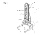
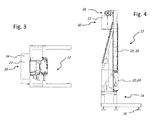
- FIGS. 1 to 4 each show a variant of a lifting column 10 of a palletizer 12, as it can be used for lifting, lowering and / or transfer of loads such as. Pallet layers with items, general cargo or beverage containers within a packaging or packaging machine.
- the illustrated Hubtechnik 1976le 10 extends in the vertical direction and is anchored to a support frame 14 which rests on a plurality of support legs 16 at the bottom.
- a lifting and lowering support and / or handling element 20 for goods to be transported which is coupled to a counterweight 22 which is vertically movable along the lifting column 10 and in the opposite direction to the carrying and / or handling element 20 .
- a counterweight 22 which is vertically movable along the lifting column 10 and in the opposite direction to the carrying and / or handling element 20 .
- From the carrying and / or handling element 20 is in the FIGS. 1 to 4 in each case only one connecting flange 24 can be seen, to which a palletizing support, a shutter head or another handling element can be attached, which is not shown here.
- a drive device 26 is attached in the form of an electric drive motor with associated winch, for the opposing lifting and lowering movements of the connecting flange 24 and the support and / or handling element 20 and the rear of the truss column 18 in vertical Direction movably guided counterweight 22 by means of suitable traction means 28 provides.
- the counterweight 22 is formed by an open-topped hollow container 30 which is filled with a loose bed of granular material 32 variable amount variable (see. Fig. 5 ).
- the hollow container 30 can optionally be open at the top or, as in the illustrated embodiment, be equipped with a pivotable cover 34, which can be opened to fill the hollow container 30.
- the amount of the bed 32 in the hollow container 30 of the counterweight 22 can be varied according to the invention, the hollow container 30 at the back of the open truss column 18 is accessible from the outside.
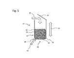
- the schematic representation of Fig. 5 illustrates the operation of the variably ballastable counterweight 22, which is movable in the vertical stroke direction 36 along the vertical direction of elongation of the lifting column 10.
- the loose bed 32 which can be introduced into the hollow container 30 by means of a filling 38 can be formed from a wide variety of suitable materials. So she can, for example, metallic Granules 40, wherein the loose bed 32 may be formed substantially by spheres or irregularly shaped granules 40 of different diameters. The spaces between larger balls 42 or bodies may advantageously be largely filled by smaller balls 44 or body.
- bulk material is, for example, steel casting in question.
- the hollow container 30 has on its underside 46 an outlet opening 48 for removal 50 of the bed 32 or a portion of the bed 32.
- This outlet opening 48 may be formed by a flap, a slider or other dosing.
- the schematic representation of Fig. 6 illustrates a variant of the variable counterweight ballastable 22, which is movable in the vertical stroke direction 36 along the vertical direction of elongation of the lifting column 10.
- the counterweight 22 may be associated with an additional weighing device 52, which may be designed differently.
- the weighing device 52 may, for example, be formed by a spring balance 54, which is arranged in the traction means 28, on which the counterweight 22 is suspended.
- weighing device 52 is also a pressure compensator 56, which may be disposed below the hollow container 30 and the support frame 14, so that the hollow container 30 can place on lowering the counterweight 22 in its lowermost stroke position with its bottom 46 there, so that the Weighing can be performed.
- the weighing device 52 can optionally function mechanically and indicate the load of the hollow container 30 by means of a scale.
- electrical variants are conceivable that provide an output signal that can be used to display the weight and / or for further data processing.
Landscapes
- Engineering & Computer Science (AREA)
- Mechanical Engineering (AREA)
- Pallets (AREA)
Description
- Die vorliegende Erfindung betrifft eine Palettier-, Stapel- und/oder Handhabungsvorrichtung mit den Merkmalen des unabhängigen Anspruchs 1.
- Es gibt zahlreiche unterschiedliche Hub- und Handhabungsvorrichtungen zum Heben oder Umsetzen von Lasten. Bei vielen der zahlreichen bekannten Hub- oder Handhabungsvorrichtungen zum Heben oder Umsetzen von Lasten befindet sich die zu hebende oder umzusetzende Last außerhalb des Schwerpunktes der Vorrichtung, so dass je nach den im Betrieb auftretenden Hebelverhältnissen Gegengewichte benötigt werden, um unzulässige Lastverhältnisse oder gar ein Umkippen der Hub- oder Handhabungsvorrichtungen zu verhindern. So benötigen bspw. Auslegerkräne für einen sicheren Betrieb ein Gegengewicht, das an einem dem horizontalen Auslegerarm gegenüber liegenden rückseitigen Stützarm angelenkt ist und verhindert, dass eine unzulässig hohe Biegebelastung auf den Mast einwirkt.
- Ein Auslegerkran zum Heben und Umsetzen von Lasten auf Baustellen mit einem veränderlichen Gegengewicht ist aus der
KR 2011 000 44 77 U - Hebeeinrichtungen, die in der Verpackungstechnik eingesetzt werden, sind in aller Regel nicht mobil, sondern stehen an einem festen Ort innerhalb einer Verpackungsstraße. Solche Hebeeinrichtungen können bspw. als Palettiervorrichtungen eingesetzt werden. Bei diesen Vorrichtungen stehen schnelle Hubbewegungen innerhalb eines definierten Bewegungsbereichs im Vordergrund, die möglichst exakt und störungsfrei ablaufen sollen. Die vertikal bewegten Hubwerke werden normalerweise elektromotorisch betrieben, wobei der Antriebsmotor zum Heben einer schweren Last einen relativ großen Energieeinsatz erfordert. Zum Senken einer schweren Last können dagegen u.U. Bremseinrichtungen erforderlich sein, sofern die Bremskraft des elektrischen Antriebsmotors nicht ausreicht. Um den Energieeinsatz für das Heben und Senken der Lasten zu reduzieren, werden Gegengewichte eingesetzt, die sich gegensinnig zu den Lasten bewegen. Für eine Optimierung des Energieeinsatzes ist es wünschenswert, die jeweiligen Massen der Hubwerke mitsamt den Lasten und des Gegengewichts aufeinander abzustimmen. Da die Massen der Lasten wechseln, ist dies in der Praxis nicht möglich, weshalb die Masse des Gegengewichts normalerweise auf eine mittlere Last des Hubwerks abgestimmt wird. Als Ballastmaterial für die Gegengewichte werden häufig gegossene Bleiplatten verwendet, die ggf. mit einer Hülle überzogen sind.
- Ein Ziel der vorliegenden Erfindung besteht darin, eine Palettier-, Stapel- und/oder Handhabungsvorrichtung mit einem Gegengewicht auszustatten, das die Nachteile des bisher meist verwendeten gegossenen Bleis vermeidet. Das Gegengewicht soll kostengünstiger und umweltfreundlicher herstellbar sein als Blei. Zudem soll die Masse des Gegengewichts möglichst einfach an unterschiedliche Lastverhältnisse anpassbar sein.
- Dieses Ziel wird mit dem Gegenstand des unabhängigen Anspruchs erreicht. Merkmale vorteilhafter Weiterbildungen der Erfindung ergeben sich aus den abhängigen Ansprüchen. Zur Erreichung des genannten Ziels schlägt die Erfindung eine Palettiervorrichtung einer Verpackungsanlage mit einem entlang einer sich vertikal erstreckenden Hubwerksäule beweglichen Trag- und/oder Handhabungselement für Transportgüter vor, das mit einem entlang der Hubwerksäule und gegensinnig zum Trag- und/oder Handhabungselement vertikal beweglichen Gegengewicht gekoppelt ist. Gemäß der vorliegenden Erfindung umfasst das Gegengewicht einen oder mehrere Hohlbehälter, der/die mit einer losen Schüttung aus granulatartigem Ballastmaterial variabler Menge befüllt ist/sind. Der oder die Hohlbehälter kann/können wahlweise oben offen oder mit einem verschließbaren Deckel ausgestattet sein, um die lose Schüttung vor Umwelteinflüssen abzuschirmen. Der Hohlbehälter kann einteilig oder mehrteilig ausgebildet sein, wobei er wahlweise in mehrere Fächer unterteilt sein kann.
- Die lose Schüttung kann aus den unterschiedlichsten geeigneten Materialien gebildet sein. So kann sie bspw. metallisches Granulat aufweisen, wobei die lose Schüttung im Wesentlichen durch Kugeln oder unregelmäßig geformtes Granulat unterschiedlichen Durchmessers oder Ausmaßes gebildet sein kann. Dabei können die Zwischenräume zwischen größeren Kugeln oder Körpern in vorteilhafter Weise durch kleinere Kugeln oder Körper weitgehend ausgefüllt sein. Besonders bevorzugt besteht das Schüttgut aus einer Mischung von unterschiedlich großen Kugeln oder Körpern. Als Schüttmaterial kommt bspw. Stahlguss o.ä. in Frage. Auch mineralisches Material wie Steine oder Glas eignet sich als Schüttgut oder Granulat, wahlweise auch Mischungen aus mineralischem und metallischem Granulat. Von Vorteil kann es u.U. sein, wenn das metallische Granulat eisenhaltig ist und unter dem Einfluss der Luftfeuchtigkeit korrodiert, so dass die einzelnen Teilchen stärker aneinander haften. Bei allen diesen Materialien kann jedoch auf Blei oder anderes teures und/oder umweltschädliches, weil schwer zu entsorgendes Material verzichtet werden.
- Eine Ausführungsvariante der erfindungsgemäßen Palettiervorrichtung kann einen Hohlkörper vorsehen, der eine oder mehrere Auslassöffnungen an der Behälterunterseite zur Entnahme der Schüttung bzw. eines Teils der Schüttung aufweist. Diese Auslassöffnung kann bspw. durch eine Klappe, einen Schieber oder ein anderes Dosierelement gebildet sein. Zudem kann es von Vorteil sein, wenn der Hohlbehälter ein von außen ablesbares Schauglas und/oder eine innenseitig an einer Wand des Behälters ablesbare Skala aufweist. Wenn diese Skalierung zudem auf die der Höhe der Schüttung entsprechende Masse des Gegengewichtes hinweist, kann diese problemlos an die typische Belastung des Hubwerks bzw. der Handhabungseinrichtung der Palettiervorrichtung angepasst werden. Eine zusätzliche Option kann darin bestehen, den Hohlbehälter mit einer Wiegeeinrichtung zur Gewichtsbestimmung auszustatten, bspw. mit einer Federwaage, die innerhalb des Zugmittels angeordnet sein kann, welches das Gegengewicht mit dem Antriebsmotor verbindet. Es ist aber auch denkbar die Wiegeeinrichtung direkt an der Unterseite des Hohlbehälters oder aber auch an dem unteren Ende der Hubwerkssäule, speziell am Boden bzw. unterem Ende innerhalb der Hubwerkssäule anzuordnen. Dies würde es ermöglichen, dass zur Gewichtsbestimmung und der eventuell notwendigen Gewichtsjustierung der Hohlbehälter auf der Wiegeeinrichtung aufsitzt, was relativ einfach mittels einer entsprechenden Steuerung des Antriebsmotors des Zugmittels und des damit in Verbindung stehenden Hohlbehälters möglich ist. So kann ohne hohen Aufwand sehr schnell das aktuelle Gegengewicht bestimmt werden und je nach Bedarf an unterschiedlichen Lastanforderungen das Gegengewicht optimal eingestellt werden.
- Herkömmliche Gegengewichte oder Ballastelemente aus Bleiplatten ermöglichen keine solche Anpassung. Bei diesen Ballastelementen fehlt die gewünschte Flexibilität zum Anpassen des Gewichts an die jeweiligen Anforderungen. Demgegenüber ermöglicht die erfindungsgemäße Vorrichtung mit ihrem variablen Gegengewicht die Handhabung, das Heben und/oder Palettieren von stark unterschiedlichen Lasten, da bei jeweils unterschiedlichen anzuhebenden und abzusenkenden Lasten ein optimaler Gewichtsausgleich des Gegengewichts ermöglicht ist, so dass sich der Einsatzbereich der erfindungsgemäßen Vorrichtung erheblich erweitern lässt.
- Soll die Höhe der Schüttung im Gegengewicht zu dessen Gewichtsanpassung variiert werden, so ist es von Vorteil, wenn der Hohlbehälter des Gegengewichts von außen zugänglich ist. Dies ist insbesondere der Fall, wenn die Hubwerksäule bspw. als offene Fachwerksäule ausgebildet ist, an dessen Rückseite das Gegengewicht in vertikaler Richtung beweglich ist. Wahlweise kann die Hubwerksäule jedoch auch als weitgehend geschlossene Hohlsäule ausgebildet sein, bei der das Gegengewicht innen in der Säule läuft. Bei einer solchen Ausführungsvariante sind entsprechende Maßnahmen vorzusehen, um den Hohlbehälter für die Variation der Schüttung zugänglich zu machen, bspw. durch eine von außen zugängliche Öffnung in der Hohlsäule der Hubwerksäule.
- Wenn im vorliegenden Zusammenhang allgemein von einer Palettier-, Stapel- und/oder Handhabungseinrichtung gesprochen wird, so sind damit bspw. Palettiervorrichtungen gemeint, die typischerweise aus einem Hubwerk und einer daran angeordneten Handhabungseinrichtung wie z.B. einer Beladestation, Beladegreifer, Beladeplatte, Jalousiekopf oder Ähnlichem bestehen. Bei solchen Palettiervorrichtungen bestehen die Hubwerke aus mindestens einer Hubwerksäule, welche durch eine rohr- oder schachtförmige oder auch fachwerkartige Säule und daran an einer Seite angeordneten vertikalen Führungen gebildet sein kann. Innerhalb der rohr- oder schachtförmigen oder fachwerkartigen Säule bietet der Hohlraum ausreichend Platz für ein Gegengewicht, welches mittels eines Riemens und über eine angetriebene Umlenkrolle in Verbindung mit der an einer Seite des Hubwerks an dessen Führungen vertikal beweglich angebrachten Beladestation bzw. Handhabungseinrichtung steht. Das Gegengewicht ist dabei meist so ausgelegt, dass das Gewicht annähernd dem Gewicht der Beladestation bzw. der Handhabungseinrichtung inklusive dem Gewicht einer ganzen Gebindelage entspricht. Die vorliegende Erfindung ermöglicht nun durch die variable Ballastierung des Gegengewichts eine optimale Anpassung an die unterschiedlichsten Einsatzfälle und Lastfälle.
- Der verwendete Begriff der Palettier-, Stapel- und/oder Handhabungseinrichtung erstreckt sich von seiner Bedeutung auch auf sog. Zwischenlageneinleger. Solche Zwischenlageneinleger werden dazu verwendet, um zwischen den einzelnen gestapelten Gebindelagen eine Zwischenlage einzulegen, der meist durch einen aus Karton bestehenden flachen Zuschnitt gebildet ist. Dies geschieht in abwechselnder Weise, so dass nach jeder Lage von Gebinden eine Zwischenlage aufgelegt werden kann. Derartige Zwischenlageneinleger ähneln hinsichtlich ihres Grundaufbaus den zuvor beschriebenen Palettiervorrichtungen. Allerdings ist anstelle einer Beladeplatte oder Beladestation eine Art Arm angebracht, der an einem Ende geeignete Greifmittel zum Ergreifen von Zwischenlagen angeordnet hat. Wenn hier von vergleichbarer oder ähnlicher Bauart die Rede ist, so bezieht sich dies auf das Grundgerüst, nicht jedoch die weiteren Konstruktionsdetails, welche natürlich auch in den Dimensionen voneinander abweichen können. Detailausführungen der Handhabungseinrichtung, des Palettierers oder des Zwischenlageneinlegers sind für die Erfindung nicht ausschlaggebend. Wesentlich für die Erfindung sind der Grundaufbau der Einrichtung selbst und das variable Gegengewicht, welche im Wesentlichen annähernd gleich sind. So weist also auch der Zwischenlageneinleger die gleichen Komponenten wie rohr- bzw. schachtförmige oder fachwerkartige Säule, Führungen, Gegengewicht, angeschweißte bzw. angeschraubte Bodenplatte, motorischer Antrieb, Riemen oder Zahnriemen, Verbindungsleitungen (pneumatisch, elektrisch) und eine Handhabungseinrichtung auf.
- Schließlich sind weitere Handhabungseinrichtungen denkbar, die Teil der Vorrichtung sein können, so bspw. Wickeleinrichtungen zur Umwicklung von Palettenlagen und/oder -stapeln mit Folie oder anderem Verpackungsmaterial, Greifarme aller Art etc.
- Im Folgenden sollen Ausführungsbeispiele die Erfindung und ihre Vorteile anhand der beigefügten Figuren näher erläutern. Die Größenverhältnisse der einzelnen Elemente zueinander in den Figuren entsprechen nicht immer den realen Größenverhältnissen, da einige Formen vereinfacht und andere Formen zur besseren Veranschaulichung vergrößert im Verhältnis zu anderen Elementen dargestellt sind.
-
Fig. 1 zeigt eine schematische Perspektivansicht einer Hubwerksäule einer Palettiervorrichtung. -
Fig. 2 zeigt eine weitere schematische Perspektivansicht der Hubwerksäule gemäßFig. 1 . -
Fig. 3 zeigt eine schematische Draufsicht auf die Hubwerksäule gemäßFig. 1 . -
Fig. 4 zeigt eine schematische Seitenansicht der Hubwerksäule gemäßFig. 1 . -
Fig. 5 zeigt eine schematische Ansicht eines mit loser Schüttung befüllbaren Gegengewichts der Palettiervorrichtung. -
Fig. 6 zeigt eine Variante des Gegengewichts gemäßFig. 5 . - Gleiche oder gleich wirkende Elemente der Erfindung sind im nachfolgend beschriebenen Ausführungsbeispiel mit gleichen Bezugsziffern bezeichnet. Der Übersicht halber weisen manche Figuren nur solche Bezugszeichen auf, die für die Beschreibung der jeweiligen Figur erforderlich sind. Die dargestellte Ausführungsform liefert lediglich ein Beispiel, wie die erfindungsgemäße Palettiervorrichtung ausgestaltet sein kann; eine abschließende Begrenzung ist damit nicht verbunden.
- Die vier schematischen Ansichten der
Figuren 1 bis 4 zeigen jeweils eine Ausführungsvariante einer Hubwerksäule 10 einer Palettiervorrichtung 12, wie sie zum Heben, Senken und/oder Umsetzen von Lasten wie bspw. Palettenlagen mit Artikeln, Stückgütern oder Getränkebehältern innerhalb einer Verpackungsanlage oder Verpackungsmaschine eingesetzt werden kann. Die dargestellte Hubwerksäule 10 erstreckt sich in vertikale Richtung und ist auf einem Stützrahmen 14 verankert, der über mehrere Stützfüße 16 am Boden aufliegt. An der Vorderseite der als Fachwerksäule 18 ausgebildeten Hubwerksäule 10 befindet sich ein heb- und senkbares Trag- und/oder Handhabungselement 20 für Transportgüter, das mit einem entlang der Hubwerksäule 10 und gegensinnig zum Trag- und/oder Handhabungselement 20 vertikal beweglichen Gegengewicht 22 gekoppelt ist. Vom Trag- und/oder Handhabungselement 20 ist in denFiguren 1 bis 4 jeweils nur ein Anschlussflansch 24 erkennbar, an dem eine Palettierauflage, ein Jalousiekopf oder ein anderes Handhabungselement befestigt werden kann, das hier jedoch nicht dargestellt ist. - Am oberen Ende der Hubwerksäule 10 ist ein Antriebseinrichtung 26 in Form eines elektrischen Antriebsmotors mit zugehöriger Winde befestigt, das für die gegensinnigen Hebe- und Senkbewegungen des Anschlussflansches 24 bzw. des Trag- und/oder Handhabungselements 20 sowie des rückseitig an der Fachwerksäule 18 in vertikaler Richtung beweglich geführten Gegengewichts 22 mittels geeigneter Zugmittel 28 sorgt.
- Wie insbesondere die
Figuren 1 und2 erkennen lassen, ist das Gegengewicht 22 durch einen oben offenen Hohlbehälter 30 gebildet, der mit einer losen Schüttung 32 aus granulatartigem Ballastmaterial variabler Menge befüllt ist (vgl.Fig. 5 ). Der Hohlbehälter 30 kann wahlweise oben offen oder wie im dargestellten Ausführungsbeispiel mit einem schwenkbaren Deckel 34 ausgestattet sein, der zum Befüllen des Hohlbehälters 30 geöffnet werden kann. Damit die Menge der Schüttung 32 im Hohlbehälter 30 des Gegengewichts 22 erfindungsgemäß variiert werden kann, ist der Hohlbehälter 30 an der Rückseite der offenen Fachwerksäule 18 von außen zugänglich. - Die schematische Darstellung der
Fig. 5 verdeutlicht die Funktionsweise des variabel ballastierbaren Gegengewichts 22, das in vertikaler Hubrichtung 36 entlang der vertikalen Längserstreckungsrichtung der Hubwerksäule 10 beweglich ist. Die in den Hohlbehälter 30 durch eine Befüllung 38 einbringbare lose Schüttung 32 kann aus den unterschiedlichsten geeigneten Materialien gebildet sein. So kann sie bspw. metallisches Granulat 40 aufweisen, wobei die lose Schüttung 32 im Wesentlichen durch Kugeln oder unregelmäßig geformtes Granulat 40 unterschiedlichen Durchmessers gebildet sein kann. Dabei können die Zwischenräume zwischen größeren Kugeln 42 oder Körpern in vorteilhafter Weise durch kleinere Kugeln 44 oder Körper weitgehend ausgefüllt sein. Als Schüttmaterial kommt bspw. Stahlguss in Frage. - Der Hohlbehälter 30 weist an seiner Unterseite 46 eine Auslassöffnung 48 zur Entnahme 50 der Schüttung 32 bzw. eines Teils der Schüttung 32 auf. Diese Auslassöffnung 48 kann durch eine Klappe, einen Schieber oder ein anderes Dosierelement gebildet sein.
- Die schematische Darstellung der
Fig. 6 verdeutlicht eine Ausführungsvariante des variabel ballastierbaren Gegengewichts 22, das in vertikaler Hubrichtung 36 entlang der vertikalen Längserstreckungsrichtung der Hubwerksäule 10 beweglich ist. Um einer optimalen Befüllung in Abstimmung auf jeweils unterschiedliche Belastungsfälle nahe kommen zu können, kann dem Gegengewicht 22 eine zusätzliche Wiegeeinrichtung 52 zugeordnet sein, die unterschiedlich ausgestaltet sein kann. So kann die Wiegeeinrichtung 52 bspw. durch eine Federwaage 54 gebildet sein, die im Zugmittel 28 angeordnet ist, an der das Gegengewicht 22 aufgehängt ist. - Als alternative Wiegeeinrichtung 52 eignet sich jedoch auch eine Druckwaage 56, die unterhalb des Hohlbehälters 30 und am Stützrahmen 14 angeordnet sein kann, so dass der Hohlbehälter 30 beim Absenken des Gegengewichts 22 in seiner unterste Hublage mit seiner Unterseite 46 dort aufsetzen kann, so dass die Wägung durchgeführt werden kann. Die Wiegeeinrichtung 52 kann wahlweise mechanisch funktionieren und mittels einer Skala die Belastung des Hohlbehälters 30 anzeigen. Selbstverständlich sind auch elektrische Varianten denkbar, die ein Ausgangssignal liefern, das zur Anzeige des Gewichts und/oder zur weiteren Datenverarbeitung verwendet werden kann.
- Die Erfindung wurde unter Bezugnahme auf eine bevorzugte Ausführungsform beschrieben. Es ist jedoch für einen Fachmann vorstellbar, dass Abwandlungen oder Änderungen der Erfindung gemacht werden können, ohne dabei den Schutzbereich der nachstehenden Ansprüche zu verlassen.
-
- 10
- Hubwerksäule
- 12
- Palettiervorrichtung
- 14
- Stützrahmen
- 16
- Stützfuß
- 18
- Fachwerksäule
- 20
- Trag- und/oder Handhabungselement
- 22
- Gegengewicht
- 24
- Anschlussflansch
- 26
- Antriebseinrichtung
- 28
- Zugmittel
- 30
- Hohlbehälter
- 32
- Schüttung
- 34
- Deckel
- 36
- vertikale Hubrichtung
- 38
- Befüllung
- 40
- Granulat
- 42
- größere Kugeln
- 44
- kleinere Kugeln
- 46
- Unterseite
- 48
- Auslassöffnung
- 50
- Entnahme
- 52
- Wiegeeinrichtung
- 54
- Federwaage
- 56
- Druckwaage
Claims (10)
- Palettier-, Stapel- und/oder Handhabungsvorrichtung (12) einer Verpackungsanlage mit einem entlang einer sich vertikal erstreckenden Hubwerksäule (10) beweglichen Trag- und/oder Handhabungselement (20) für Transportgüter, das mit einem entlang der Hubwerksäule (10) und gegensinnig zum Trag- und/oder Handhabungselement (20) vertikal beweglichen Gegengewicht (22) gekoppelt ist, das einen oder mehrere Hohlbehälter (30) umfasst, der/die mit einer losen Schüttung (32) aus granulatartigem Ballastmaterial variabler Menge befüllt ist/sind.
- Palettiervorrichtung nach Anspruch 1, die wenigstens einen oben offenen Hohlbehälter (30) aufweist, der das Gegengewicht (22) bildet.
- Palettiervorrichtung nach Anspruch 1 oder 2, deren wenigstens einer Hohlbehälter (30) einen verschließbaren Deckel (34) aufweist.
- Palettiervorrichtung nach einem der Ansprüche 1 bis 3, deren wenigstens einer Hohlbehälter (30) in mehrere Fächer unterteilt ist.
- Palettiervorrichtung nach einem der Ansprüche 1 bis 4, bei welcher der wenigstens eine Hohlbehälter (30) eine lose Schüttung (32) aus metallischem Granulat aufweist.
- Palettiervorrichtung nach Anspruch 5, bei der die lose Schüttung (32) im Wesentlichen durch Kugeln (42, 44) oder unregelmäßig geformtes Granulat unterschiedlichen Durchmessers gebildet ist.
- Palettiervorrichtung nach Anspruch 6, bei der Zwischenräume zwischen größeren Kugeln (42) oder Körpern durch kleinere Kugeln (44) oder Körper weitgehend ausgefüllt sind.
- Palettiervorrichtung nach einem der Ansprüche 1 bis 7, bei welcher der wenigstens eine Hohlkörper (30) eine oder mehrere Auslassöffnungen (48) an der Behälterunterseite (46) zur Entnahme (50) der Schüttung (32) aufweist.
- Palettiervorrichtung nach einem der Ansprüche 1 bis 8, bei welcher der Hohlbehälter (30) ein von außen ablesbares Schauglas und/oder eine innenseitig an einer Wand des Behälters (30) ablesbare Skala aufweist.
- Palettiervorrichtung nach einem der Ansprüche 1 bis 9, bei welcher der Hohlbehälter (30) mit einer Wiegeeinrichtung (52, 54, 56) zur Gewichtsbestimmung der Schüttung (32) versehen oder gekoppelt ist.
Applications Claiming Priority (1)
| Application Number | Priority Date | Filing Date | Title |
|---|---|---|---|
| DE102012106825.9A DE102012106825A1 (de) | 2012-07-26 | 2012-07-26 | Palettier-, Stapel- und/oder Handhabungsvorrichtung |
Publications (2)
| Publication Number | Publication Date |
|---|---|
| EP2690038A1 true EP2690038A1 (de) | 2014-01-29 |
| EP2690038B1 EP2690038B1 (de) | 2015-03-04 |
Family
ID=48874770
Family Applications (1)
| Application Number | Title | Priority Date | Filing Date |
|---|---|---|---|
| EP20130174650 Active EP2690038B1 (de) | 2012-07-26 | 2013-07-02 | Palettier-, Stapel- und/oder Handhabungsvorrichtung |
Country Status (3)
| Country | Link |
|---|---|
| EP (1) | EP2690038B1 (de) |
| CN (1) | CN103569682B (de) |
| DE (1) | DE102012106825A1 (de) |
Cited By (1)
| Publication number | Priority date | Publication date | Assignee | Title |
|---|---|---|---|---|
| CN104229483A (zh) * | 2014-09-30 | 2014-12-24 | 洛阳中冶重工机械有限公司 | 一种码垛搬运机械的软带提升装置 |
Families Citing this family (2)
| Publication number | Priority date | Publication date | Assignee | Title |
|---|---|---|---|---|
| CN106882578A (zh) * | 2015-12-15 | 2017-06-23 | 中电和瑞科技有限公司 | 一种自动卸药装置及自动卸药方法 |
| CN108860538A (zh) * | 2018-06-12 | 2018-11-23 | 上海海洋大学 | 一种精密可调压载装置 |
Citations (2)
| Publication number | Priority date | Publication date | Assignee | Title |
|---|---|---|---|---|
| DE1116598B (de) * | 1957-05-09 | 1961-11-02 | Michel Dramard | Maschine zum selbsttaetigen Aufschichten von Saecken auf Gestelle |
| KR20110004477U (ko) | 2009-10-29 | 2011-05-06 | 이영섭 | 자동 균형조정 타워 크레인 |
Family Cites Families (10)
| Publication number | Priority date | Publication date | Assignee | Title |
|---|---|---|---|---|
| US2809756A (en) * | 1951-01-12 | 1957-10-15 | Schield Bantam Company | Crane |
| SE444428B (sv) * | 1981-05-23 | 1986-04-14 | Okura Yusoki Co Ltd | Pallastningsanordning |
| US4597707A (en) * | 1984-08-17 | 1986-07-01 | General Machine Design, Inc. | Automatic operating palletizer |
| DE3638991A1 (de) * | 1986-11-14 | 1988-05-19 | Focke & Co | Foerdereinrichtung, insbesondere palettierer |
| AU726963B2 (en) * | 1996-02-29 | 2000-11-30 | Mammoet Europe B.V. | Hoisting device |
| CN200961065Y (zh) * | 2006-05-23 | 2007-10-17 | 广州市万世德包装机械有限公司 | 全自动码垛机的垒垛机构 |
| KR100858960B1 (ko) * | 2007-12-11 | 2008-09-17 | 강성순 | 엘리베이터 웨이트 |
| CN201301210Y (zh) * | 2008-11-13 | 2009-09-02 | 李昆华 | 半圆轨道自动调节配重重心的起重装置 |
| CN101979293B (zh) * | 2010-11-02 | 2012-05-09 | 无锡力马化工机械有限公司 | 一种码垛整形机 |
| CN102328829B (zh) * | 2011-08-09 | 2012-12-26 | 山东矿机迈科建材机械有限公司 | 托盘上下架装置 |
-
2012
- 2012-07-26 DE DE102012106825.9A patent/DE102012106825A1/de not_active Withdrawn
-
2013
- 2013-07-02 EP EP20130174650 patent/EP2690038B1/de active Active
- 2013-07-26 CN CN201310320704.2A patent/CN103569682B/zh active Active
Patent Citations (2)
| Publication number | Priority date | Publication date | Assignee | Title |
|---|---|---|---|---|
| DE1116598B (de) * | 1957-05-09 | 1961-11-02 | Michel Dramard | Maschine zum selbsttaetigen Aufschichten von Saecken auf Gestelle |
| KR20110004477U (ko) | 2009-10-29 | 2011-05-06 | 이영섭 | 자동 균형조정 타워 크레인 |
Cited By (1)
| Publication number | Priority date | Publication date | Assignee | Title |
|---|---|---|---|---|
| CN104229483A (zh) * | 2014-09-30 | 2014-12-24 | 洛阳中冶重工机械有限公司 | 一种码垛搬运机械的软带提升装置 |
Also Published As
| Publication number | Publication date |
|---|---|
| EP2690038B1 (de) | 2015-03-04 |
| CN103569682A (zh) | 2014-02-12 |
| DE102012106825A1 (de) | 2014-06-12 |
| CN103569682B (zh) | 2016-09-28 |
Similar Documents
| Publication | Publication Date | Title |
|---|---|---|
| EP2444341B1 (de) | Vorrichtung zum Behandeln von Stückgütern einer Transporteinheit, insbesondere eines Wechselbehälters, und Entladevorrichtung | |
| DE102010009873A1 (de) | Lastaufnahmevorrichtung für ein Regalbediengerät, Regalbediengerät und Lagersystem | |
| DE102007017288B4 (de) | Anlage zum Einladen von Gepäckstücken in Container | |
| EP2128047B2 (de) | Aufnahmevorrichtung für ein Förderfahrzeug und Verfahren zur deren Benutzung | |
| EP1999040A1 (de) | Vorrichtung und verfahren zum einsetzen und abnehmen von twist-lock-container-sicherungsbeschlägen | |
| DE102011120739A1 (de) | Universelles Lastaufnahmemittel für palettenlose Handhabung von Paletten-Ladegütern | |
| DE102015121846B4 (de) | Transportfahrzeug für Container | |
| EP2690038B1 (de) | Palettier-, Stapel- und/oder Handhabungsvorrichtung | |
| DE202006018017U1 (de) | Palettierer, insbesondere Portal-Palettierer | |
| WO2016192947A1 (de) | Übergabevorrichtung und verfahren | |
| EP2690039B1 (de) | Palettier-, Stapel- und/oder Handhabungsvorrichtung und Verfahren zu deren Umbau | |
| DE102007047405A1 (de) | Verfahren und Vorrichtung zum Bereitstellen unterschiedlicher Hilfsmaterialien durch einen Palettierroboter | |
| DE2544192A1 (de) | Anordnung zur mechanischen aufnahme und packung von waren, insbesondere in warenspeichern | |
| AT13398U1 (de) | Vertikaler schachtförderer und -stapler | |
| EP1907310B1 (de) | Anhänger für ein kraftfahrzeug | |
| DE2330629C2 (de) | Entpalettiereinrichtung | |
| DE3213421C2 (de) | ||
| DE202011106303U1 (de) | Befüllvorrichtung für Großbeschicker | |
| DE2336803A1 (de) | Vorrichtung zum ergreifen eines aufrechtstehenden fasses oder eines aehnlichen behaelters | |
| DE60104493T2 (de) | Verfahren zum Transport von Verpackungen, insbesonders Flaschen, und deren Präsentation zum Verkauf, sowie Rollcontainer und darin verwendete Vorrichtung | |
| DE102009060769B4 (de) | Fahrzeugaufbau zum Transport von Flüssigkeiten und/oder Feststoffen | |
| DE582677C (de) | Beschickeinrichtung fuer Kuebelfoerderer | |
| DE3323168A1 (de) | Mobile abfuell- und beladevorrichtung | |
| WO1980002415A1 (fr) | Procede et dispositif pour palettiser des sacs | |
| EP4378838A1 (de) | Automatische fassabfüllanlage sowie verfahren zur automatischen abfüllung von stahlfässern mit edelstahlschrott |
Legal Events
| Date | Code | Title | Description |
|---|---|---|---|
| PUAI | Public reference made under article 153(3) epc to a published international application that has entered the european phase |
Free format text: ORIGINAL CODE: 0009012 |
|
| AK | Designated contracting states |
Kind code of ref document: A1 Designated state(s): AL AT BE BG CH CY CZ DE DK EE ES FI FR GB GR HR HU IE IS IT LI LT LU LV MC MK MT NL NO PL PT RO RS SE SI SK SM TR |
|
| AX | Request for extension of the european patent |
Extension state: BA ME |
|
| 17P | Request for examination filed |
Effective date: 20140116 |
|
| RBV | Designated contracting states (corrected) |
Designated state(s): AL AT BE BG CH CY CZ DE DK EE ES FI FR GB GR HR HU IE IS IT LI LT LU LV MC MK MT NL NO PL PT RO RS SE SI SK SM TR |
|
| GRAP | Despatch of communication of intention to grant a patent |
Free format text: ORIGINAL CODE: EPIDOSNIGR1 |
|
| INTG | Intention to grant announced |
Effective date: 20141021 |
|
| GRAS | Grant fee paid |
Free format text: ORIGINAL CODE: EPIDOSNIGR3 |
|
| GRAA | (expected) grant |
Free format text: ORIGINAL CODE: 0009210 |
|
| AK | Designated contracting states |
Kind code of ref document: B1 Designated state(s): AL AT BE BG CH CY CZ DE DK EE ES FI FR GB GR HR HU IE IS IT LI LT LU LV MC MK MT NL NO PL PT RO RS SE SI SK SM TR |
|
| REG | Reference to a national code |
Ref country code: GB Ref legal event code: FG4D Free format text: NOT ENGLISH |
|
| REG | Reference to a national code |
Ref country code: CH Ref legal event code: EP |
|
| REG | Reference to a national code |
Ref country code: IE Ref legal event code: FG4D Free format text: LANGUAGE OF EP DOCUMENT: GERMAN |
|
| REG | Reference to a national code |
Ref country code: AT Ref legal event code: REF Ref document number: 713661 Country of ref document: AT Kind code of ref document: T Effective date: 20150415 |
|
| REG | Reference to a national code |
Ref country code: DE Ref legal event code: R096 Ref document number: 502013000402 Country of ref document: DE Effective date: 20150416 |
|
| REG | Reference to a national code |
Ref country code: FR Ref legal event code: PLFP Year of fee payment: 3 |
|
| REG | Reference to a national code |
Ref country code: NL Ref legal event code: VDEP Effective date: 20150304 |
|
| PG25 | Lapsed in a contracting state [announced via postgrant information from national office to epo] |
Ref country code: HR Free format text: LAPSE BECAUSE OF FAILURE TO SUBMIT A TRANSLATION OF THE DESCRIPTION OR TO PAY THE FEE WITHIN THE PRESCRIBED TIME-LIMIT Effective date: 20150304 Ref country code: SE Free format text: LAPSE BECAUSE OF FAILURE TO SUBMIT A TRANSLATION OF THE DESCRIPTION OR TO PAY THE FEE WITHIN THE PRESCRIBED TIME-LIMIT Effective date: 20150304 Ref country code: NO Free format text: LAPSE BECAUSE OF FAILURE TO SUBMIT A TRANSLATION OF THE DESCRIPTION OR TO PAY THE FEE WITHIN THE PRESCRIBED TIME-LIMIT Effective date: 20150604 Ref country code: LT Free format text: LAPSE BECAUSE OF FAILURE TO SUBMIT A TRANSLATION OF THE DESCRIPTION OR TO PAY THE FEE WITHIN THE PRESCRIBED TIME-LIMIT Effective date: 20150304 Ref country code: FI Free format text: LAPSE BECAUSE OF FAILURE TO SUBMIT A TRANSLATION OF THE DESCRIPTION OR TO PAY THE FEE WITHIN THE PRESCRIBED TIME-LIMIT Effective date: 20150304 Ref country code: ES Free format text: LAPSE BECAUSE OF FAILURE TO SUBMIT A TRANSLATION OF THE DESCRIPTION OR TO PAY THE FEE WITHIN THE PRESCRIBED TIME-LIMIT Effective date: 20150304 |
|
| REG | Reference to a national code |
Ref country code: LT Ref legal event code: MG4D |
|
| PG25 | Lapsed in a contracting state [announced via postgrant information from national office to epo] |
Ref country code: GR Free format text: LAPSE BECAUSE OF FAILURE TO SUBMIT A TRANSLATION OF THE DESCRIPTION OR TO PAY THE FEE WITHIN THE PRESCRIBED TIME-LIMIT Effective date: 20150605 Ref country code: RS Free format text: LAPSE BECAUSE OF FAILURE TO SUBMIT A TRANSLATION OF THE DESCRIPTION OR TO PAY THE FEE WITHIN THE PRESCRIBED TIME-LIMIT Effective date: 20150304 Ref country code: LV Free format text: LAPSE BECAUSE OF FAILURE TO SUBMIT A TRANSLATION OF THE DESCRIPTION OR TO PAY THE FEE WITHIN THE PRESCRIBED TIME-LIMIT Effective date: 20150304 |
|
| PG25 | Lapsed in a contracting state [announced via postgrant information from national office to epo] |
Ref country code: NL Free format text: LAPSE BECAUSE OF FAILURE TO SUBMIT A TRANSLATION OF THE DESCRIPTION OR TO PAY THE FEE WITHIN THE PRESCRIBED TIME-LIMIT Effective date: 20150304 |
|
| PG25 | Lapsed in a contracting state [announced via postgrant information from national office to epo] |
Ref country code: EE Free format text: LAPSE BECAUSE OF FAILURE TO SUBMIT A TRANSLATION OF THE DESCRIPTION OR TO PAY THE FEE WITHIN THE PRESCRIBED TIME-LIMIT Effective date: 20150304 Ref country code: RO Free format text: LAPSE BECAUSE OF FAILURE TO SUBMIT A TRANSLATION OF THE DESCRIPTION OR TO PAY THE FEE WITHIN THE PRESCRIBED TIME-LIMIT Effective date: 20150304 Ref country code: CZ Free format text: LAPSE BECAUSE OF FAILURE TO SUBMIT A TRANSLATION OF THE DESCRIPTION OR TO PAY THE FEE WITHIN THE PRESCRIBED TIME-LIMIT Effective date: 20150304 Ref country code: SK Free format text: LAPSE BECAUSE OF FAILURE TO SUBMIT A TRANSLATION OF THE DESCRIPTION OR TO PAY THE FEE WITHIN THE PRESCRIBED TIME-LIMIT Effective date: 20150304 Ref country code: PT Free format text: LAPSE BECAUSE OF FAILURE TO SUBMIT A TRANSLATION OF THE DESCRIPTION OR TO PAY THE FEE WITHIN THE PRESCRIBED TIME-LIMIT Effective date: 20150706 |
|
| PG25 | Lapsed in a contracting state [announced via postgrant information from national office to epo] |
Ref country code: PL Free format text: LAPSE BECAUSE OF FAILURE TO SUBMIT A TRANSLATION OF THE DESCRIPTION OR TO PAY THE FEE WITHIN THE PRESCRIBED TIME-LIMIT Effective date: 20150304 Ref country code: IS Free format text: LAPSE BECAUSE OF FAILURE TO SUBMIT A TRANSLATION OF THE DESCRIPTION OR TO PAY THE FEE WITHIN THE PRESCRIBED TIME-LIMIT Effective date: 20150704 |
|
| REG | Reference to a national code |
Ref country code: DE Ref legal event code: R097 Ref document number: 502013000402 Country of ref document: DE |
|
| PLBE | No opposition filed within time limit |
Free format text: ORIGINAL CODE: 0009261 |
|
| STAA | Information on the status of an ep patent application or granted ep patent |
Free format text: STATUS: NO OPPOSITION FILED WITHIN TIME LIMIT |
|
| PG25 | Lapsed in a contracting state [announced via postgrant information from national office to epo] |
Ref country code: DK Free format text: LAPSE BECAUSE OF FAILURE TO SUBMIT A TRANSLATION OF THE DESCRIPTION OR TO PAY THE FEE WITHIN THE PRESCRIBED TIME-LIMIT Effective date: 20150304 |
|
| 26N | No opposition filed |
Effective date: 20151207 |
|
| PG25 | Lapsed in a contracting state [announced via postgrant information from national office to epo] |
Ref country code: SI Free format text: LAPSE BECAUSE OF FAILURE TO SUBMIT A TRANSLATION OF THE DESCRIPTION OR TO PAY THE FEE WITHIN THE PRESCRIBED TIME-LIMIT Effective date: 20150304 Ref country code: MC Free format text: LAPSE BECAUSE OF FAILURE TO SUBMIT A TRANSLATION OF THE DESCRIPTION OR TO PAY THE FEE WITHIN THE PRESCRIBED TIME-LIMIT Effective date: 20150304 |
|
| PG25 | Lapsed in a contracting state [announced via postgrant information from national office to epo] |
Ref country code: LU Free format text: LAPSE BECAUSE OF FAILURE TO SUBMIT A TRANSLATION OF THE DESCRIPTION OR TO PAY THE FEE WITHIN THE PRESCRIBED TIME-LIMIT Effective date: 20150702 |
|
| REG | Reference to a national code |
Ref country code: IE Ref legal event code: MM4A |
|
| REG | Reference to a national code |
Ref country code: FR Ref legal event code: PLFP Year of fee payment: 4 |
|
| PG25 | Lapsed in a contracting state [announced via postgrant information from national office to epo] |
Ref country code: IE Free format text: LAPSE BECAUSE OF NON-PAYMENT OF DUE FEES Effective date: 20150702 |
|
| REG | Reference to a national code |
Ref country code: CH Ref legal event code: PL |
|
| PG25 | Lapsed in a contracting state [announced via postgrant information from national office to epo] |
Ref country code: MT Free format text: LAPSE BECAUSE OF FAILURE TO SUBMIT A TRANSLATION OF THE DESCRIPTION OR TO PAY THE FEE WITHIN THE PRESCRIBED TIME-LIMIT Effective date: 20150304 |
|
| PG25 | Lapsed in a contracting state [announced via postgrant information from national office to epo] |
Ref country code: CH Free format text: LAPSE BECAUSE OF NON-PAYMENT OF DUE FEES Effective date: 20160731 Ref country code: LI Free format text: LAPSE BECAUSE OF NON-PAYMENT OF DUE FEES Effective date: 20160731 |
|
| PG25 | Lapsed in a contracting state [announced via postgrant information from national office to epo] |
Ref country code: BG Free format text: LAPSE BECAUSE OF FAILURE TO SUBMIT A TRANSLATION OF THE DESCRIPTION OR TO PAY THE FEE WITHIN THE PRESCRIBED TIME-LIMIT Effective date: 20150304 Ref country code: HU Free format text: LAPSE BECAUSE OF FAILURE TO SUBMIT A TRANSLATION OF THE DESCRIPTION OR TO PAY THE FEE WITHIN THE PRESCRIBED TIME-LIMIT; INVALID AB INITIO Effective date: 20130702 |
|
| REG | Reference to a national code |
Ref country code: FR Ref legal event code: PLFP Year of fee payment: 5 |
|
| PG25 | Lapsed in a contracting state [announced via postgrant information from national office to epo] |
Ref country code: CY Free format text: LAPSE BECAUSE OF FAILURE TO SUBMIT A TRANSLATION OF THE DESCRIPTION OR TO PAY THE FEE WITHIN THE PRESCRIBED TIME-LIMIT Effective date: 20150304 |
|
| PG25 | Lapsed in a contracting state [announced via postgrant information from national office to epo] |
Ref country code: BE Free format text: LAPSE BECAUSE OF NON-PAYMENT OF DUE FEES Effective date: 20150731 |
|
| GBPC | Gb: european patent ceased through non-payment of renewal fee |
Effective date: 20170702 |
|
| PG25 | Lapsed in a contracting state [announced via postgrant information from national office to epo] |
Ref country code: GB Free format text: LAPSE BECAUSE OF NON-PAYMENT OF DUE FEES Effective date: 20170702 |
|
| PG25 | Lapsed in a contracting state [announced via postgrant information from national office to epo] |
Ref country code: SM Free format text: LAPSE BECAUSE OF FAILURE TO SUBMIT A TRANSLATION OF THE DESCRIPTION OR TO PAY THE FEE WITHIN THE PRESCRIBED TIME-LIMIT Effective date: 20150304 |
|
| REG | Reference to a national code |
Ref country code: FR Ref legal event code: PLFP Year of fee payment: 6 |
|
| PG25 | Lapsed in a contracting state [announced via postgrant information from national office to epo] |
Ref country code: TR Free format text: LAPSE BECAUSE OF FAILURE TO SUBMIT A TRANSLATION OF THE DESCRIPTION OR TO PAY THE FEE WITHIN THE PRESCRIBED TIME-LIMIT Effective date: 20150304 Ref country code: MK Free format text: LAPSE BECAUSE OF FAILURE TO SUBMIT A TRANSLATION OF THE DESCRIPTION OR TO PAY THE FEE WITHIN THE PRESCRIBED TIME-LIMIT Effective date: 20150304 |
|
| PG25 | Lapsed in a contracting state [announced via postgrant information from national office to epo] |
Ref country code: AL Free format text: LAPSE BECAUSE OF FAILURE TO SUBMIT A TRANSLATION OF THE DESCRIPTION OR TO PAY THE FEE WITHIN THE PRESCRIBED TIME-LIMIT Effective date: 20150304 |
|
| REG | Reference to a national code |
Ref country code: AT Ref legal event code: MM01 Ref document number: 713661 Country of ref document: AT Kind code of ref document: T Effective date: 20180702 |
|
| PG25 | Lapsed in a contracting state [announced via postgrant information from national office to epo] |
Ref country code: AT Free format text: LAPSE BECAUSE OF NON-PAYMENT OF DUE FEES Effective date: 20180702 |
|
| P01 | Opt-out of the competence of the unified patent court (upc) registered |
Effective date: 20230523 |
|
| REG | Reference to a national code |
Ref country code: DE Ref legal event code: R082 Ref document number: 502013000402 Country of ref document: DE Representative=s name: BENNINGER, JOHANNES, DIPL.-ING., DE |
|
| PGFP | Annual fee paid to national office [announced via postgrant information from national office to epo] |
Ref country code: FR Payment date: 20250610 Year of fee payment: 13 |
|
| PGFP | Annual fee paid to national office [announced via postgrant information from national office to epo] |
Ref country code: DE Payment date: 20250604 Year of fee payment: 13 |
|
| PGFP | Annual fee paid to national office [announced via postgrant information from national office to epo] |
Ref country code: IT Payment date: 20250623 Year of fee payment: 13 |