EP2689944B1 - Refrigeration system for transportation - Google Patents
Refrigeration system for transportation Download PDFInfo
- Publication number
- EP2689944B1 EP2689944B1 EP13177446.5A EP13177446A EP2689944B1 EP 2689944 B1 EP2689944 B1 EP 2689944B1 EP 13177446 A EP13177446 A EP 13177446A EP 2689944 B1 EP2689944 B1 EP 2689944B1
- Authority
- EP
- European Patent Office
- Prior art keywords
- secondary battery
- chiller
- generator
- power
- engine
- Prior art date
- Legal status (The legal status is an assumption and is not a legal conclusion. Google has not performed a legal analysis and makes no representation as to the accuracy of the status listed.)
- Active
Links
- 238000005057 refrigeration Methods 0.000 title claims description 50
- 238000010248 power generation Methods 0.000 claims description 13
- 238000001514 detection method Methods 0.000 claims description 5
- 238000010586 diagram Methods 0.000 description 4
- 238000006243 chemical reaction Methods 0.000 description 2
- 230000000694 effects Effects 0.000 description 2
- 238000000034 method Methods 0.000 description 2
- 238000004378 air conditioning Methods 0.000 description 1
- 230000007423 decrease Effects 0.000 description 1
- 230000003247 decreasing effect Effects 0.000 description 1
Images


Classifications
-
- B—PERFORMING OPERATIONS; TRANSPORTING
- B60—VEHICLES IN GENERAL
- B60H—ARRANGEMENTS OF HEATING, COOLING, VENTILATING OR OTHER AIR-TREATING DEVICES SPECIALLY ADAPTED FOR PASSENGER OR GOODS SPACES OF VEHICLES
- B60H1/00—Heating, cooling or ventilating [HVAC] devices
- B60H1/00421—Driving arrangements for parts of a vehicle air-conditioning
- B60H1/00428—Driving arrangements for parts of a vehicle air-conditioning electric
-
- F—MECHANICAL ENGINEERING; LIGHTING; HEATING; WEAPONS; BLASTING
- F25—REFRIGERATION OR COOLING; COMBINED HEATING AND REFRIGERATION SYSTEMS; HEAT PUMP SYSTEMS; MANUFACTURE OR STORAGE OF ICE; LIQUEFACTION SOLIDIFICATION OF GASES
- F25D—REFRIGERATORS; COLD ROOMS; ICE-BOXES; COOLING OR FREEZING APPARATUS NOT OTHERWISE PROVIDED FOR
- F25D29/00—Arrangement or mounting of control or safety devices
- F25D29/003—Arrangement or mounting of control or safety devices for movable devices
-
- Y—GENERAL TAGGING OF NEW TECHNOLOGICAL DEVELOPMENTS; GENERAL TAGGING OF CROSS-SECTIONAL TECHNOLOGIES SPANNING OVER SEVERAL SECTIONS OF THE IPC; TECHNICAL SUBJECTS COVERED BY FORMER USPC CROSS-REFERENCE ART COLLECTIONS [XRACs] AND DIGESTS
- Y02—TECHNOLOGIES OR APPLICATIONS FOR MITIGATION OR ADAPTATION AGAINST CLIMATE CHANGE
- Y02T—CLIMATE CHANGE MITIGATION TECHNOLOGIES RELATED TO TRANSPORTATION
- Y02T10/00—Road transport of goods or passengers
- Y02T10/80—Technologies aiming to reduce greenhouse gasses emissions common to all road transportation technologies
- Y02T10/88—Optimized components or subsystems, e.g. lighting, actively controlled glasses
Definitions
- the present invention relates to a so-called sub-engine type refrigeration system for transportation provided with an engine exclusively used to drive a chiller, such as disclosed in WO 2011/056642 A2 .
- PTL 1 discloses a sub-engine type air-conditioning system in which a sub engine is used to drive a compressor, an evaporator fan and the like and to also drive an alternator, and power generated by the alternator is used to charge a battery for an air conditioner, whereby an air-conditioner side electric load including an evaporator fan motor can be driven by power of the battery for an air conditioner while the sub engine is stopped.
- PTL 2 discloses a sub-engine type refrigeration system for transportation in which a motor generator and a compressor can be driven by a sub engine, and a chiller-side electric load is driven and a battery is charged by the generated power from the motor generator.
- the sub engine continues the operation to charge a battery, and once the battery is charged to a specified value or higher, the sub engine is stopped until the amount of charge in the battery reaches a preset value, and the motor generator is driven by power of the battery so as to drive the compressor and the other electric load and to operate a chiller.
- PTL 3 and PTL 4 disclose a chiller for chill vehicles that is configured to drive a chiller-side electrical load by generated power from a generator which is driven by an engine for driving a vehicle, and charge a battery by the generated power from the generator.
- the chiller-side electric load can be driven by power from the battery when vehicle engine speed drops depending on a vehicle driving condition and an output voltage of the generator is decreased or when the power is not supplied from outside because the engine is stopped.
- WO2011056642 (A2 ) discloses a refrigeration system for a mobile unit and a method for operating the same.
- US2009085400 (A1 ) refers to a single- or dual-inverter auxiliary power conversion apparatus and system and narrow-hysteresis charging method.
- US2008034773 (A1 ) teaches a system for maintaining a selected temperature in a refrigeration unit of a food service vehicle.
- the invention disclosed in PTL 2 in order to minimize on/off cycles of the sub engine in a low load region and allow the sub engine to operate in a high load region as much as possible, when the amount of charge in the battery is at or above the preset value, the sub engine is stopped and the motor generator is driven by the power of the battery, so that the compressor and the electric load on the chiller side are driven by motive power and generated power from the motor generator, and when the amount of charge in the battery decreases to the preset value or lower, the sub engine is operated and the compressor and the motor generator are driven, so that the battery is charged.
- the invention disclosed in PTL 2 is not intended to maintain the high generation efficiency of the generator with respect to variations of power consumption on the chiller side and improve the energy efficiency of a sub-engine type refrigeration system for transportation.
- the secondary battery which is charged by power of the generator when the generator has excess output, and discharges when the generator output is insufficient or when the engine for driving a vehicle is stopped to stabilize a power supply circuit
- the secondary battery serves as a temporary back-up power supply for when the power generation is insufficient or when the power generation is stopped.
- the inventions disclosed in PTL 3 and PTL 4 are not also intended to improve the energy efficiency of the sub-engine type refrigeration system for transportation by actively using the secondary battery.
- the present invention has been made in view of such circumstances, and an object of the present invention is to provide a refrigeration system for transportation in which an AC generator can be operated at a consistently high load factor by controlling the amount of charge in a secondary battery with respect to variations in power consumption on a chiller side, thereby maintaining the high generation efficiency and improving the energy efficiency.
- the invention relates to a sub-engine type refrigeration system for transportation according to claim 1.
- a refrigeration system for transportation of the present invention is a sub-engine type refrigeration system for transportation, which includes an engine for driving a chiller and an AC generator driven by the engine, wherein all or part of an electric load of the chiller is driven by power generated by the AC generator.
- the system includes a secondary battery which is capable of storing the power generated by the AC generator, and a control unit which controls so that, when a state of charge of the secondary battery is at or above a control lower limit value, the engine is stopped and the chiller's electric load is driven by the power of the secondary battery, and when the state of charge of the secondary battery is below the control lower limit value while the chiller's electric load is driven by the power of the secondary battery, the engine is operated and the AC generator starts power generation, whereby the chiller's electric load is driven by the power of the AC generator, and also controls the amount of charge to the secondary battery so as to maintain a load factor of the AC generator substantially at a rated load.
- a system which can use the secondary battery actively by controlling so that, when the state of charge (SOC) of the secondary battery is above the control lower limit value, the engine is stopped, the chiller's electric load is driven by the power of the secondary battery, thereby improving the energy efficiency.
- SOC state of charge
- the engine is operated and the AC generator starts power generation, whereby the chiller's electric load is driven by the power of the AC generator, and also controlling the amount of charge to the secondary battery so as to maintain the load factor of the AC generator substantially at a rated load and controlling the amount of charge to the secondary battery with respect to variations in power consumption on the chiller side, the AC generator is operated substantially at a rated load leading to a consistently high load factor, thereby maintaining the generation efficiency substantially at its maximum.
- SOC state of charge
- the refrigeration system for transportation of the present invention may include the control unit having a function that when the state of charge of the secondary battery is above a control upper limit value, the operation of the engine is stopped, and the chiller's electric load is driven by the power of the secondary battery until the state of charge of the secondary battery is below the control lower limit value.
- the refrigeration system for transportation of the present invention includes the control unit having a function of controlling so that, when the state of charge of the secondary battery is below the control lower limit value while the chiller's electric load is driven by the power of the secondary battery, the engine is operated and the AC generator starts power generation, whereby the chiller's electric load is driven by the generated power from the AC generator, and also controlling the load factor of the engine to 70 to 100% to drive the AC generator.
- the amount of charge to the secondary battery is variably controlled in accordance with variations in power consumption on the chiller side.
- the load factor of the engine is always controlled to 70 to 100%, and the load factor of the AC generator is maintained substantially at a rated load to thereby achieve the operation at high load factor.
- the generation efficiency substantially at its maximum and improve the energy efficiency in the sub-engine type refrigeration system for transportation.
- the refrigeration system for transportation of the present invention may include the control unit having a function that operable time of the chiller by the secondary battery is calculated on the basis of a detection value of power consumption by the chiller's electric load, and when the operable time of the chiller is at a predetermined time or larger, the driving of the chiller's electric load is switched to the driving by the power of the secondary battery even when the secondary battery is being charge-controlled.
- the operable time of the chiller by the secondary battery is calculated on the basis of power consumption of the chiller-side electric load, and when the operable time of the chiller is at a predetermined time or larger, the operation of the engine is stopped, and the driving of the chiller-side electric load is switched to the driving by the power of the secondary battery even when the secondary battery is being charge-controlled, to thereby further reduce the operating ratio of the engine and the AC generator.
- the operating ratio by the secondary battery can be increased, and the energy efficiency in the refrigeration system for transportation can be further improved.
- the refrigeration system for transportation of the present invention may include the secondary battery configured to be capable of being charged not only by power generated by the AC generator but also by power from an external AC power supply, and configured to disconnect an output circuit of the AC generator when the system is connected with the external AC power supply.
- the chiller can be operated while the secondary battery is charged, by connecting the external AC power supply and disconnecting the output circuit of the AC generator.
- the chiller can be operated and the secondary battery can be charged.
- the refrigeration system for transportation of the present invention may be configured to disconnect the secondary battery from a utility grid and always drive the AC generator by the engine when the failure of the secondary battery occurs, so that the operation of the system is switchable to drive the chiller's electric load by the generated power from the AC generator.
- the chiller can be normally operated in spite of the failure of the secondary battery.
- a highly versatile system may be provided which may be also applied to a sub-engine type refrigeration system for transportation which is not equipped with the secondary battery and drives the chiller's electric load by always driving the AC generator by the engine.
- the system is provided which can use the secondary battery actively by controlling so that, when the state of charge (SOC) of the secondary battery is above the control lower limit value, the engine is stopped, the chiller's electric load is driven by the power of the secondary battery, thereby improving the energy efficiency.
- SOC state of charge
- the engine is operated and the AC generator starts power generation, whereby the chiller's electric load is driven by the power of the AC generator, and also controlling the amount of charge to the secondary battery so as to maintain the load factor of the AC generator substantially at a rated load, and controlling the amount of charge to the secondary battery with respect to variations in power consumption on the chiller side, AC generator is operated substantially at a rated load leading to a consistently high load factor and the generation efficiency is maintained substantially at its maximum.
- the energy efficiency in the sub-engine type refrigeration system for transportation can be significantly improved by using a secondary battery.
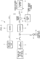
- Fig. 1 shows an electrical schematic diagram of a sub-engine type refrigeration system for transportation according to an embodiment of the present invention.
- a refrigeration system for transportation 1 of the present embodiment is a sub-engine type refrigeration system for transportation 1 provided with an engine exclusively used to drive a chiller (hereafter referred to as "sub engine") 2, and includes an AC generator 3 driven by the sub engine 2.
- the AC generator 3 is driven by the sub engine 2 and generates three-phase AC power. Since the sub engine 2 and the AC generator 3 are generally designed to achieve the highest efficient operation substantially at a rated load, stable operation substantially at a rated load contributes to improvement in generation efficiency and overall energy efficiency.
- the converter 5 is an AC/DC converter and includes a rectifier circuit, an electric power conversion system, or the like which converts AC power to DC power.
- a configuration is adopted in which the power converted from AC to DC by the converter 5 is applied to a chiller-side electric load 7 including a motor compressor, a condenser fan motor, an evaporator fan motor, and the like via an inverter 6.
- the inverter 6 converts DC power from the converter 5 to three-phase AC power of a command frequency corresponding to a refrigeration load to apply to the electric load 7.
- the refrigeration system for transportation 1 also includes a secondary battery 8 that stores power which is generated by the AC generator 3 and then converted from the AC to DC through the converter 5. It is assumed that the secondary battery 8 has capacity enough to operate the chiller's electric load 7 only by the power charged therein over a considerable period of time once a state of charge (SOC) is above a control upper limit value.
- the secondary battery 8 for a chiller is configured to be capable of being charged, via a charge/discharge control unit 9, by the remainder of DC power converted through the converter 5 after part of the power is consumed on the chiller-side.
- a configuration is adopted in which the power stored in the secondary battery 8 is discharged via the charge/discharge control unit 9, converted to three-phase AC power through the inverter 6, and applied to the chiller's electric load 7 when the sub engine 2 is stopped.
- a power supply plug 11 which is connectable with an external AC power supply 10 such as a commercial power supply, is provided between the converter 5 and the contact point 4.
- an external AC power supply 10 such as a commercial power supply
- a configuration is adopted in which, by connecting the power supply plug 11 to the external AC power supply 10, power from the external AC power supply 10 enables operation of the chiller (electric load 7) and charging of the secondary battery 8 even when the sub engine 2 and the AC generator 3 are stopped.
- An output circuit is adapted to be disconnected from the AC generator 3 by the contact point 4 when this external AC power supply 10 is used for operation.
- the refrigeration system for transportation 1 further includes a control unit 12 that has a function of maintaining and controlling the generation efficiency substantially at its maximum by controlling start and stop of the sub engine 2 and the AC generator 3 in accordance with the state of charge (SOC) of the secondary battery 8, and controlling the amount of charge to the secondary battery 8 to control the sub engine 2 and the AC generator 3 so that they can operate at a consistently high load factor (for example, substantially at a rated load) when the sub engine 2 and the AC generator 3 are operated.
- SOC state of charge
- control unit 12 has the function of controlling so that, on the basis of a detection value and other values from a current sensor 13, when the state of charge (SOC) of the secondary battery 8 is at or above the control lower limit value, the sub engine 2 is stopped and the chiller's electric load 7 is driven by the power of the secondary battery 8, and when the state of charge (SOC) of the secondary battery 8 is below the control lower limit value while the chiller's electric load 7 is driven by the power of the secondary battery 8, the sub engine 2 is operated and the AC generator 3 starts power generation, whereby the chiller's electric load 7 is driven by the power generated from the AC generator 3, and also controlling the amount of charge to the secondary battery 8 so that the load factor of the AC generator 3 is stabilized substantially at a rated load.
- SOC state of charge
- control unit 12 has the following functions.
- the control unit 12 uses the secondary battery 8 actively by the above-described functions, and controls the charge and discharge thereof so that the operating ratio of the sub engine 2 and the AC generator 3 is minimized.
- the sub-engine type refrigeration system for transportation 1 includes the secondary battery 8 which is capable of storing the power generated by the AC generator 3 driven by the sub engine 2.
- the control unit 12 therefor controls so that, when the state of charge (SOC) of the secondary battery 8 is at or above the control lower limit value, the sub engine 2 is stopped and the chiller's electric load 7 is driven by the power of the secondary battery 8, and when the state of charge (SOC) of the secondary battery 8 is below the control lower limit value while the chiller's electric load 7 is driven by the power of the secondary battery 8, the sub engine 2 is operated and the AC generator 3 starts power generation, whereby the chiller's electric load 7 is driven by the power of the AC generator 3, and also controls the amount of charge to the secondary battery 8 so that the load factor of the AC generator 3 becomes a high load factor substantially at a rated load.
- SOC state of charge
- the system is configured to be able to use the secondary battery 8 actively by controlling so that, when the state of charge (SOC) of the secondary battery 8 is above the control lower limit value, the sub engine 2 is stopped and the chiller's electric load 7 is driven by the power of the secondary battery 8, thereby improving the energy efficiency.
- SOC state of charge
- the sub engine 2 is operated and the AC generator 3 starts power generation, whereby the chiller's electric load 7 is driven by the generated power from the AC generator 3.
- the amount of charge to the secondary battery 8 is controlled so that the load factor of the AC generator 3 is stabilized substantially at a rated load, and the amount of charge to the secondary battery 8 is controlled with respect to variations in power consumption on the chiller side. Then, the AC generator 3 is operated substantially at a rated load leading to a consistently high load factor, thereby maintaining the generation efficiency substantially at its maximum.
- the AC generator 3 and the sub engine 2 can be operated with the generation efficiency maintained substantially at its maximum, and thus, the energy efficiency in the sub-engine type refrigeration system for transportation 1 can be significantly improved by using the secondary battery 8.
- the sub engine 2 when the state of charge (SOC) of the secondary battery 8 is below the control lower limit value while the chiller's electric load 7 is driven by the power of the secondary battery 8, the sub engine 2 is operated and the AC generator 3 starts power generation, whereby the chiller's electric load 7 is driven by the generated power from the AC generator 3.
- the load factor of the sub engine 2 is controlled to 70 to 100% to drive the AC generator 3, and the amount of charge to the secondary battery 8 is variably controlled in accordance with variations in power consumption on the chiller side as indicated by (2) and (3) shown in Fig. 2 and Fig. 3 .
- the load factor of the sub engine 2 can be always controlled to 70 to 100% when the sub engine 2 is operated to generate the power by the AC generator 3, to thereby maintain the load factor of the AC generator 3 substantially at a rated load and achieve the stable operation at a high load factor.
- the operable time of the chiller by the secondary battery 8 is calculated on the basis of a detection value of the power consumption by the chiller's electric load 7.
- the driving of the chiller's electric load 7 is switched to the driving by the power of the secondary battery 8 even when the secondary battery 8 is being charge-controlled.
- the operable time of the chiller by the secondary battery 8 is calculated on the basis of the power consumption of the chiller-side electric load 7, when the operable time of the chiller is at a predetermined time or larger, the operation of the sub engine 2 is stopped even when the secondary battery 8 is being charge-controlled, and the driving of the chiller-side electric load 7 is switched to the driving by the power of the secondary battery 8, to thereby further reduce the operating ratio of the sub engine 2 and the AC generator 3.
- the operable time of the chiller by the secondary battery 8 may be calculated by division between power consumption per unit time by the chiller's electric load 7 and the electric power stored in the secondary battery 8.
- the secondary battery 8 is configured to be capable of being charged not only by the power generated by the AC generator 3, but also by the power from the external AC power supply 10 by stopping the sub engine 2 and connecting the power supply plug 11 to the external AC power supply 10, and is configured to disconnect the output circuit of the AC generator 3 by the contact point 4 when the power supply plug 11 is connected with the external AC power supply 10.
- This enables the chiller to be operated while the secondary battery 8 is being charged by connecting the power supply plug 11 to other external AC power supply 10 such as a commercial power supply if available and disconnecting the output circuit of the AC generator 3 even in the situation that a vehicle equipped with a chiller is being parked and the sub engine 2 cannot be operated. Accordingly, the chiller can be operated and the secondary battery 8 can be charged even in the situation that the sub engine 2 and the AC generator 3 are stopped.
- the chiller when the failure of the secondary battery 8 occurs, the secondary battery 8 is disconnected from the utility grid and the AC generator 3 is always driven by the sub engine 2, so that the operation of the system is switchable to drive the chiller's electric load 7 by the generated power from the AC generator 3.
- the chiller can be operated by disconnecting secondary battery 8 from the utility grid, always driving the AC generator 3 by the sub engine 2 and driving the chiller's electric load 7 by power generated from the AC generator 3. Therefore, the chiller can be normally operated in spite of the failure of the secondary battery 8.
- a highly versatile system may be provided which may be also applied to a sub-engine type refrigeration system for transportation which is not equipped with the secondary battery 8 and drives the chiller's electric load 7 by always driving the AC generator 3 by the sub engine 2.
- a connection between the sub engine 2 and the AC generator 3 can be either a directly-connected structure or connection via a centrifugal clutch.
- a motor compressor, a condenser fan motor, an evaporator fan motor, and the like are exemplified, but the other electric load may be included therein, or any of these electric loads may be exempted therefrom.
Landscapes
- Engineering & Computer Science (AREA)
- Physics & Mathematics (AREA)
- Mechanical Engineering (AREA)
- Thermal Sciences (AREA)
- Chemical & Material Sciences (AREA)
- Combustion & Propulsion (AREA)
- General Engineering & Computer Science (AREA)
- Devices That Are Associated With Refrigeration Equipment (AREA)
Applications Claiming Priority (1)
| Application Number | Priority Date | Filing Date | Title |
|---|---|---|---|
| JP2012163782A JP6071300B2 (ja) | 2012-07-24 | 2012-07-24 | 輸送用冷凍システム |
Publications (3)
| Publication Number | Publication Date |
|---|---|
| EP2689944A2 EP2689944A2 (en) | 2014-01-29 |
| EP2689944A3 EP2689944A3 (en) | 2016-05-25 |
| EP2689944B1 true EP2689944B1 (en) | 2019-10-09 |
Family
ID=48808226
Family Applications (1)
| Application Number | Title | Priority Date | Filing Date |
|---|---|---|---|
| EP13177446.5A Active EP2689944B1 (en) | 2012-07-24 | 2013-07-22 | Refrigeration system for transportation |
Country Status (2)
| Country | Link |
|---|---|
| EP (1) | EP2689944B1 (ja) |
| JP (1) | JP6071300B2 (ja) |
Cited By (1)
| Publication number | Priority date | Publication date | Assignee | Title |
|---|---|---|---|---|
| US12097751B2 (en) | 2018-12-31 | 2024-09-24 | Thermo King Llc | Methods and systems for providing predictive energy consumption feedback for powering a transport climate control system |
Families Citing this family (33)
| Publication number | Priority date | Publication date | Assignee | Title |
|---|---|---|---|---|
| CN203959038U (zh) * | 2014-05-16 | 2014-11-26 | 单位45有限公司 | 特种陆路冷藏箱 |
| JP2016056998A (ja) * | 2014-09-09 | 2016-04-21 | 株式会社デンソー | 冷凍装置及びコンテナ用冷凍システム |
| EP3472541B1 (en) | 2016-06-17 | 2023-04-05 | Carrier Corporation | Mechanical subcooler with battery supplement |
| WO2018073372A1 (de) * | 2016-10-20 | 2018-04-26 | Terramark Markencreation Gmbh | Kühlcontainer |
| CN111148952A (zh) | 2017-10-06 | 2020-05-12 | 开利公司 | 具有能量存储设备的运输制冷系统 |
| CN111163956A (zh) * | 2017-10-09 | 2020-05-15 | 开利公司 | 用于运输制冷系统的高压辅助功率单元 |
| EP3626490A1 (en) | 2018-09-19 | 2020-03-25 | Thermo King Corporation | Methods and systems for power and load management of a transport climate control system |
| EP3626489A1 (en) | 2018-09-19 | 2020-03-25 | Thermo King Corporation | Methods and systems for energy management of a transport climate control system |
| US11034213B2 (en) | 2018-09-29 | 2021-06-15 | Thermo King Corporation | Methods and systems for monitoring and displaying energy use and energy cost of a transport vehicle climate control system or a fleet of transport vehicle climate control systems |
| US11273684B2 (en) | 2018-09-29 | 2022-03-15 | Thermo King Corporation | Methods and systems for autonomous climate control optimization of a transport vehicle |
| US10870333B2 (en) | 2018-10-31 | 2020-12-22 | Thermo King Corporation | Reconfigurable utility power input with passive voltage booster |
| US11059352B2 (en) | 2018-10-31 | 2021-07-13 | Thermo King Corporation | Methods and systems for augmenting a vehicle powered transport climate control system |
| US10926610B2 (en) | 2018-10-31 | 2021-02-23 | Thermo King Corporation | Methods and systems for controlling a mild hybrid system that powers a transport climate control system |
| US10875497B2 (en) | 2018-10-31 | 2020-12-29 | Thermo King Corporation | Drive off protection system and method for preventing drive off |
| US11022451B2 (en) | 2018-11-01 | 2021-06-01 | Thermo King Corporation | Methods and systems for generation and utilization of supplemental stored energy for use in transport climate control |
| US11554638B2 (en) | 2018-12-28 | 2023-01-17 | Thermo King Llc | Methods and systems for preserving autonomous operation of a transport climate control system |
| EP3906174B1 (en) | 2018-12-31 | 2024-05-29 | Thermo King LLC | Methods and systems for providing feedback for a transport climate control system |
| EP3906172B1 (en) | 2018-12-31 | 2024-04-03 | Thermo King LLC | Methods and systems for notifying and mitigating a suboptimal event occurring in a transport climate control system |
| US11072321B2 (en) | 2018-12-31 | 2021-07-27 | Thermo King Corporation | Systems and methods for smart load shedding of a transport vehicle while in transit |
| EP3906175A1 (en) | 2018-12-31 | 2021-11-10 | Thermo King Corporation | Methods and systems for providing predictive energy consumption feedback for powering a transport climate control system using external data |
| US11458802B2 (en) | 2019-09-09 | 2022-10-04 | Thermo King Corporation | Optimized power management for a transport climate control energy source |
| US11135894B2 (en) | 2019-09-09 | 2021-10-05 | Thermo King Corporation | System and method for managing power and efficiently sourcing a variable voltage for a transport climate control system |
| EP3789221B1 (en) | 2019-09-09 | 2024-06-26 | Thermo King LLC | Prioritized power delivery for facilitating transport climate control |
| US11214118B2 (en) | 2019-09-09 | 2022-01-04 | Thermo King Corporation | Demand-side power distribution management for a plurality of transport climate control systems |
| US10985511B2 (en) | 2019-09-09 | 2021-04-20 | Thermo King Corporation | Optimized power cord for transferring power to a transport climate control system |
| US11203262B2 (en) | 2019-09-09 | 2021-12-21 | Thermo King Corporation | Transport climate control system with an accessory power distribution unit for managing transport climate control loads |
| EP3790157A1 (en) | 2019-09-09 | 2021-03-10 | Thermo King Corporation | Optimized power distribution to transport climate control systems amongst one or more electric supply equipment stations |
| US11376922B2 (en) | 2019-09-09 | 2022-07-05 | Thermo King Corporation | Transport climate control system with a self-configuring matrix power converter |
| US11420495B2 (en) | 2019-09-09 | 2022-08-23 | Thermo King Corporation | Interface system for connecting a vehicle and a transport climate control system |
| US11489431B2 (en) | 2019-12-30 | 2022-11-01 | Thermo King Corporation | Transport climate control system power architecture |
| JP2021165621A (ja) * | 2020-04-08 | 2021-10-14 | 日栄インテック株式会社 | リーファーコンテナ |
| JP7391788B2 (ja) * | 2020-07-28 | 2023-12-05 | ヤンマーホールディングス株式会社 | ヒートポンプ装置 |
| US20220136758A1 (en) * | 2020-11-05 | 2022-05-05 | Carrier Corporation | Transport refrigeration system energy management system and method |
Family Cites Families (13)
| Publication number | Priority date | Publication date | Assignee | Title |
|---|---|---|---|---|
| JPH10300313A (ja) * | 1997-04-25 | 1998-11-13 | Mitsubishi Heavy Ind Ltd | 蓄冷型保冷装置 |
| JPH114506A (ja) | 1997-06-12 | 1999-01-06 | Aqueous Res:Kk | 車両発電装置 |
| JP3029601B2 (ja) * | 1998-04-23 | 2000-04-04 | 松下電器産業株式会社 | 車両用冷凍冷蔵装置 |
| JP4199380B2 (ja) | 1999-08-12 | 2008-12-17 | 東芝キヤリア株式会社 | 冷凍車用冷凍装置 |
| JP2001180254A (ja) | 1999-12-20 | 2001-07-03 | Mitsubishi Heavy Ind Ltd | Iss制御車両用サブエンジン方式空調装置 |
| JP4426737B2 (ja) * | 2000-06-28 | 2010-03-03 | 東芝キヤリア株式会社 | 車両用冷凍装置 |
| JP2003097871A (ja) * | 2001-09-25 | 2003-04-03 | Mitsubishi Heavy Ind Ltd | 陸上輸送用冷凍装置 |
| US20080034773A1 (en) * | 2006-08-14 | 2008-02-14 | Vahe Karapetian | System and method for automatic control of catering truck refrigeration |
| US7834478B2 (en) * | 2006-12-05 | 2010-11-16 | Paul Baumann | Single- or dual-inverter auxiliary power conversion apparatus and system and narrow-hysteresis charging method |
| JP5210542B2 (ja) * | 2007-05-11 | 2013-06-12 | 三菱重工業株式会社 | 輸送用冷凍装置 |
| JP5417876B2 (ja) * | 2009-02-12 | 2014-02-19 | ダイキン工業株式会社 | 冷凍装置 |
| ES2736774T3 (es) * | 2009-10-27 | 2020-01-07 | Carrier Corp | Sistema de refrigeración híbrido para una unidad móvil y método de operación |
| US8536834B2 (en) * | 2010-12-23 | 2013-09-17 | Thermo King Corporation | Mobile environment-controlled unit and method of operating a mobile environment-controlled unit |
-
2012
- 2012-07-24 JP JP2012163782A patent/JP6071300B2/ja active Active
-
2013
- 2013-07-22 EP EP13177446.5A patent/EP2689944B1/en active Active
Non-Patent Citations (1)
| Title |
|---|
| None * |
Cited By (1)
| Publication number | Priority date | Publication date | Assignee | Title |
|---|---|---|---|---|
| US12097751B2 (en) | 2018-12-31 | 2024-09-24 | Thermo King Llc | Methods and systems for providing predictive energy consumption feedback for powering a transport climate control system |
Also Published As
| Publication number | Publication date |
|---|---|
| EP2689944A2 (en) | 2014-01-29 |
| EP2689944A3 (en) | 2016-05-25 |
| JP6071300B2 (ja) | 2017-02-01 |
| JP2014025593A (ja) | 2014-02-06 |
Similar Documents
| Publication | Publication Date | Title |
|---|---|---|
| EP2689944B1 (en) | Refrigeration system for transportation | |
| US9371005B2 (en) | Battery management apparatus for an electric vehicle, and method for managing same | |
| US7923866B2 (en) | Power supply system and vehicle including the same, and method of controlling the same | |
| US8639413B2 (en) | Vehicle power supply system and method for controlling the same | |
| US20200148142A1 (en) | Multiple vehicular charge sources and loads | |
| US10960775B2 (en) | DC/DC conversion unit | |
| US20110084648A1 (en) | Hybrid energy storage system | |
| JP5210542B2 (ja) | 輸送用冷凍装置 | |
| US8736218B2 (en) | Power supply device for electric vehicle | |
| US20080257622A1 (en) | Motor Vehicle Comprising a Solar Module | |
| US10933762B2 (en) | DC/DC conversion unit | |
| KR101551086B1 (ko) | 연료전지 비상전원 공급시스템 | |
| CA2886166A1 (en) | Power management and environmental control system for vehicles | |
| WO2019031419A1 (ja) | 制御装置、輸送用冷凍システム、制御方法及び充電率算出方法 | |
| JP2013126843A (ja) | 車両用電動冷凍サイクル装置 | |
| JP2003224999A (ja) | 車両用電源装置 | |
| JP2001197788A (ja) | 自動車用空調装置 | |
| KR101186467B1 (ko) | 냉동, 냉장 및 온장 식품 운반용 차량의 전력 제어장치 및 방법 | |
| CN104410145B (zh) | 一种电动空调电源系统 | |
| JP2010142052A (ja) | ヒートポンプ式空気調和装置の室外機 | |
| CN111231606B (zh) | 车载空调、运行方法、控制装置和计算机可读存储介质 | |
| JP7430978B2 (ja) | 電源システム及びその制御方法 | |
| JP2004225991A (ja) | 車載用冷凍装置 | |
| JP2004274920A (ja) | 車両用電源装置 | |
| JP3971653B2 (ja) | 車両用冷凍装置 |
Legal Events
| Date | Code | Title | Description |
|---|---|---|---|
| PUAI | Public reference made under article 153(3) epc to a published international application that has entered the european phase |
Free format text: ORIGINAL CODE: 0009012 |
|
| AK | Designated contracting states |
Kind code of ref document: A2 Designated state(s): AL AT BE BG CH CY CZ DE DK EE ES FI FR GB GR HR HU IE IS IT LI LT LU LV MC MK MT NL NO PL PT RO RS SE SI SK SM TR |
|
| AX | Request for extension of the european patent |
Extension state: BA ME |
|
| PUAL | Search report despatched |
Free format text: ORIGINAL CODE: 0009013 |
|
| AK | Designated contracting states |
Kind code of ref document: A3 Designated state(s): AL AT BE BG CH CY CZ DE DK EE ES FI FR GB GR HR HU IE IS IT LI LT LU LV MC MK MT NL NO PL PT RO RS SE SI SK SM TR |
|
| AX | Request for extension of the european patent |
Extension state: BA ME |
|
| RIC1 | Information provided on ipc code assigned before grant |
Ipc: F25D 29/00 20060101ALI20160418BHEP Ipc: B60H 1/00 20060101AFI20160418BHEP |
|
| STAA | Information on the status of an ep patent application or granted ep patent |
Free format text: STATUS: REQUEST FOR EXAMINATION WAS MADE |
|
| 17P | Request for examination filed |
Effective date: 20161121 |
|
| RBV | Designated contracting states (corrected) |
Designated state(s): AL AT BE BG CH CY CZ DE DK EE ES FI FR GB GR HR HU IE IS IT LI LT LU LV MC MK MT NL NO PL PT RO RS SE SI SK SM TR |
|
| RAP1 | Party data changed (applicant data changed or rights of an application transferred) |
Owner name: MITSUBISHI HEAVY INDUSTRIES THERMAL SYSTEMS, LTD. |
|
| STAA | Information on the status of an ep patent application or granted ep patent |
Free format text: STATUS: EXAMINATION IS IN PROGRESS |
|
| 17Q | First examination report despatched |
Effective date: 20180824 |
|
| GRAP | Despatch of communication of intention to grant a patent |
Free format text: ORIGINAL CODE: EPIDOSNIGR1 |
|
| STAA | Information on the status of an ep patent application or granted ep patent |
Free format text: STATUS: GRANT OF PATENT IS INTENDED |
|
| INTG | Intention to grant announced |
Effective date: 20190429 |
|
| GRAS | Grant fee paid |
Free format text: ORIGINAL CODE: EPIDOSNIGR3 |
|
| GRAA | (expected) grant |
Free format text: ORIGINAL CODE: 0009210 |
|
| STAA | Information on the status of an ep patent application or granted ep patent |
Free format text: STATUS: THE PATENT HAS BEEN GRANTED |
|
| AK | Designated contracting states |
Kind code of ref document: B1 Designated state(s): AL AT BE BG CH CY CZ DE DK EE ES FI FR GB GR HR HU IE IS IT LI LT LU LV MC MK MT NL NO PL PT RO RS SE SI SK SM TR |
|
| REG | Reference to a national code |
Ref country code: GB Ref legal event code: FG4D |
|
| REG | Reference to a national code |
Ref country code: CH Ref legal event code: EP |
|
| REG | Reference to a national code |
Ref country code: DE Ref legal event code: R096 Ref document number: 602013061389 Country of ref document: DE |
|
| REG | Reference to a national code |
Ref country code: IE Ref legal event code: FG4D |
|
| REG | Reference to a national code |
Ref country code: AT Ref legal event code: REF Ref document number: 1188375 Country of ref document: AT Kind code of ref document: T Effective date: 20191115 |
|
| REG | Reference to a national code |
Ref country code: NL Ref legal event code: MP Effective date: 20191009 |
|
| REG | Reference to a national code |
Ref country code: LT Ref legal event code: MG4D |
|
| REG | Reference to a national code |
Ref country code: AT Ref legal event code: MK05 Ref document number: 1188375 Country of ref document: AT Kind code of ref document: T Effective date: 20191009 |
|
| PG25 | Lapsed in a contracting state [announced via postgrant information from national office to epo] |
Ref country code: LV Free format text: LAPSE BECAUSE OF FAILURE TO SUBMIT A TRANSLATION OF THE DESCRIPTION OR TO PAY THE FEE WITHIN THE PRESCRIBED TIME-LIMIT Effective date: 20191009 Ref country code: NL Free format text: LAPSE BECAUSE OF FAILURE TO SUBMIT A TRANSLATION OF THE DESCRIPTION OR TO PAY THE FEE WITHIN THE PRESCRIBED TIME-LIMIT Effective date: 20191009 Ref country code: SE Free format text: LAPSE BECAUSE OF FAILURE TO SUBMIT A TRANSLATION OF THE DESCRIPTION OR TO PAY THE FEE WITHIN THE PRESCRIBED TIME-LIMIT Effective date: 20191009 Ref country code: AT Free format text: LAPSE BECAUSE OF FAILURE TO SUBMIT A TRANSLATION OF THE DESCRIPTION OR TO PAY THE FEE WITHIN THE PRESCRIBED TIME-LIMIT Effective date: 20191009 Ref country code: PL Free format text: LAPSE BECAUSE OF FAILURE TO SUBMIT A TRANSLATION OF THE DESCRIPTION OR TO PAY THE FEE WITHIN THE PRESCRIBED TIME-LIMIT Effective date: 20191009 Ref country code: ES Free format text: LAPSE BECAUSE OF FAILURE TO SUBMIT A TRANSLATION OF THE DESCRIPTION OR TO PAY THE FEE WITHIN THE PRESCRIBED TIME-LIMIT Effective date: 20191009 Ref country code: PT Free format text: LAPSE BECAUSE OF FAILURE TO SUBMIT A TRANSLATION OF THE DESCRIPTION OR TO PAY THE FEE WITHIN THE PRESCRIBED TIME-LIMIT Effective date: 20200210 Ref country code: LT Free format text: LAPSE BECAUSE OF FAILURE TO SUBMIT A TRANSLATION OF THE DESCRIPTION OR TO PAY THE FEE WITHIN THE PRESCRIBED TIME-LIMIT Effective date: 20191009 Ref country code: NO Free format text: LAPSE BECAUSE OF FAILURE TO SUBMIT A TRANSLATION OF THE DESCRIPTION OR TO PAY THE FEE WITHIN THE PRESCRIBED TIME-LIMIT Effective date: 20200109 Ref country code: GR Free format text: LAPSE BECAUSE OF FAILURE TO SUBMIT A TRANSLATION OF THE DESCRIPTION OR TO PAY THE FEE WITHIN THE PRESCRIBED TIME-LIMIT Effective date: 20200110 Ref country code: FI Free format text: LAPSE BECAUSE OF FAILURE TO SUBMIT A TRANSLATION OF THE DESCRIPTION OR TO PAY THE FEE WITHIN THE PRESCRIBED TIME-LIMIT Effective date: 20191009 Ref country code: BG Free format text: LAPSE BECAUSE OF FAILURE TO SUBMIT A TRANSLATION OF THE DESCRIPTION OR TO PAY THE FEE WITHIN THE PRESCRIBED TIME-LIMIT Effective date: 20200109 |
|
| PG25 | Lapsed in a contracting state [announced via postgrant information from national office to epo] |
Ref country code: HR Free format text: LAPSE BECAUSE OF FAILURE TO SUBMIT A TRANSLATION OF THE DESCRIPTION OR TO PAY THE FEE WITHIN THE PRESCRIBED TIME-LIMIT Effective date: 20191009 Ref country code: RS Free format text: LAPSE BECAUSE OF FAILURE TO SUBMIT A TRANSLATION OF THE DESCRIPTION OR TO PAY THE FEE WITHIN THE PRESCRIBED TIME-LIMIT Effective date: 20191009 Ref country code: IS Free format text: LAPSE BECAUSE OF FAILURE TO SUBMIT A TRANSLATION OF THE DESCRIPTION OR TO PAY THE FEE WITHIN THE PRESCRIBED TIME-LIMIT Effective date: 20200224 |
|
| PG25 | Lapsed in a contracting state [announced via postgrant information from national office to epo] |
Ref country code: AL Free format text: LAPSE BECAUSE OF FAILURE TO SUBMIT A TRANSLATION OF THE DESCRIPTION OR TO PAY THE FEE WITHIN THE PRESCRIBED TIME-LIMIT Effective date: 20191009 |
|
| REG | Reference to a national code |
Ref country code: DE Ref legal event code: R097 Ref document number: 602013061389 Country of ref document: DE |
|
| PG2D | Information on lapse in contracting state deleted |
Ref country code: IS |
|
| PG25 | Lapsed in a contracting state [announced via postgrant information from national office to epo] |
Ref country code: CZ Free format text: LAPSE BECAUSE OF FAILURE TO SUBMIT A TRANSLATION OF THE DESCRIPTION OR TO PAY THE FEE WITHIN THE PRESCRIBED TIME-LIMIT Effective date: 20191009 Ref country code: DK Free format text: LAPSE BECAUSE OF FAILURE TO SUBMIT A TRANSLATION OF THE DESCRIPTION OR TO PAY THE FEE WITHIN THE PRESCRIBED TIME-LIMIT Effective date: 20191009 Ref country code: EE Free format text: LAPSE BECAUSE OF FAILURE TO SUBMIT A TRANSLATION OF THE DESCRIPTION OR TO PAY THE FEE WITHIN THE PRESCRIBED TIME-LIMIT Effective date: 20191009 Ref country code: RO Free format text: LAPSE BECAUSE OF FAILURE TO SUBMIT A TRANSLATION OF THE DESCRIPTION OR TO PAY THE FEE WITHIN THE PRESCRIBED TIME-LIMIT Effective date: 20191009 Ref country code: IS Free format text: LAPSE BECAUSE OF FAILURE TO SUBMIT A TRANSLATION OF THE DESCRIPTION OR TO PAY THE FEE WITHIN THE PRESCRIBED TIME-LIMIT Effective date: 20200209 |
|
| PLBE | No opposition filed within time limit |
Free format text: ORIGINAL CODE: 0009261 |
|
| STAA | Information on the status of an ep patent application or granted ep patent |
Free format text: STATUS: NO OPPOSITION FILED WITHIN TIME LIMIT |
|
| PG25 | Lapsed in a contracting state [announced via postgrant information from national office to epo] |
Ref country code: IT Free format text: LAPSE BECAUSE OF FAILURE TO SUBMIT A TRANSLATION OF THE DESCRIPTION OR TO PAY THE FEE WITHIN THE PRESCRIBED TIME-LIMIT Effective date: 20191009 Ref country code: SK Free format text: LAPSE BECAUSE OF FAILURE TO SUBMIT A TRANSLATION OF THE DESCRIPTION OR TO PAY THE FEE WITHIN THE PRESCRIBED TIME-LIMIT Effective date: 20191009 Ref country code: SM Free format text: LAPSE BECAUSE OF FAILURE TO SUBMIT A TRANSLATION OF THE DESCRIPTION OR TO PAY THE FEE WITHIN THE PRESCRIBED TIME-LIMIT Effective date: 20191009 |
|
| 26N | No opposition filed |
Effective date: 20200710 |
|
| PG25 | Lapsed in a contracting state [announced via postgrant information from national office to epo] |
Ref country code: SI Free format text: LAPSE BECAUSE OF FAILURE TO SUBMIT A TRANSLATION OF THE DESCRIPTION OR TO PAY THE FEE WITHIN THE PRESCRIBED TIME-LIMIT Effective date: 20191009 |
|
| PG25 | Lapsed in a contracting state [announced via postgrant information from national office to epo] |
Ref country code: MC Free format text: LAPSE BECAUSE OF FAILURE TO SUBMIT A TRANSLATION OF THE DESCRIPTION OR TO PAY THE FEE WITHIN THE PRESCRIBED TIME-LIMIT Effective date: 20191009 |
|
| REG | Reference to a national code |
Ref country code: CH Ref legal event code: PL |
|
| GBPC | Gb: european patent ceased through non-payment of renewal fee |
Effective date: 20200722 |
|
| REG | Reference to a national code |
Ref country code: BE Ref legal event code: MM Effective date: 20200731 |
|
| PG25 | Lapsed in a contracting state [announced via postgrant information from national office to epo] |
Ref country code: LI Free format text: LAPSE BECAUSE OF NON-PAYMENT OF DUE FEES Effective date: 20200731 Ref country code: CH Free format text: LAPSE BECAUSE OF NON-PAYMENT OF DUE FEES Effective date: 20200731 Ref country code: GB Free format text: LAPSE BECAUSE OF NON-PAYMENT OF DUE FEES Effective date: 20200722 Ref country code: LU Free format text: LAPSE BECAUSE OF NON-PAYMENT OF DUE FEES Effective date: 20200722 |
|
| PG25 | Lapsed in a contracting state [announced via postgrant information from national office to epo] |
Ref country code: BE Free format text: LAPSE BECAUSE OF NON-PAYMENT OF DUE FEES Effective date: 20200731 |
|
| PG25 | Lapsed in a contracting state [announced via postgrant information from national office to epo] |
Ref country code: IE Free format text: LAPSE BECAUSE OF NON-PAYMENT OF DUE FEES Effective date: 20200722 |
|
| PG25 | Lapsed in a contracting state [announced via postgrant information from national office to epo] |
Ref country code: TR Free format text: LAPSE BECAUSE OF FAILURE TO SUBMIT A TRANSLATION OF THE DESCRIPTION OR TO PAY THE FEE WITHIN THE PRESCRIBED TIME-LIMIT Effective date: 20191009 Ref country code: MT Free format text: LAPSE BECAUSE OF FAILURE TO SUBMIT A TRANSLATION OF THE DESCRIPTION OR TO PAY THE FEE WITHIN THE PRESCRIBED TIME-LIMIT Effective date: 20191009 Ref country code: CY Free format text: LAPSE BECAUSE OF FAILURE TO SUBMIT A TRANSLATION OF THE DESCRIPTION OR TO PAY THE FEE WITHIN THE PRESCRIBED TIME-LIMIT Effective date: 20191009 |
|
| PG25 | Lapsed in a contracting state [announced via postgrant information from national office to epo] |
Ref country code: MK Free format text: LAPSE BECAUSE OF FAILURE TO SUBMIT A TRANSLATION OF THE DESCRIPTION OR TO PAY THE FEE WITHIN THE PRESCRIBED TIME-LIMIT Effective date: 20191009 |
|
| REG | Reference to a national code |
Ref country code: DE Ref legal event code: R082 Ref document number: 602013061389 Country of ref document: DE Representative=s name: CBDL PATENTANWAELTE GBR, DE |
|
| PGFP | Annual fee paid to national office [announced via postgrant information from national office to epo] |
Ref country code: DE Payment date: 20230531 Year of fee payment: 11 |
|
| PGFP | Annual fee paid to national office [announced via postgrant information from national office to epo] |
Ref country code: FR Payment date: 20240611 Year of fee payment: 12 |