EP3626489A1 - Methods and systems for energy management of a transport climate control system - Google Patents
Methods and systems for energy management of a transport climate control system Download PDFInfo
- Publication number
- EP3626489A1 EP3626489A1 EP18382672.6A EP18382672A EP3626489A1 EP 3626489 A1 EP3626489 A1 EP 3626489A1 EP 18382672 A EP18382672 A EP 18382672A EP 3626489 A1 EP3626489 A1 EP 3626489A1
- Authority
- EP
- European Patent Office
- Prior art keywords
- vehicle
- power
- network
- power network
- climate control
- Prior art date
- Legal status (The legal status is an assumption and is not a legal conclusion. Google has not performed a legal analysis and makes no representation as to the accuracy of the status listed.)
- Pending
Links
Images


Classifications
-
- B—PERFORMING OPERATIONS; TRANSPORTING
- B60—VEHICLES IN GENERAL
- B60L—PROPULSION OF ELECTRICALLY-PROPELLED VEHICLES; SUPPLYING ELECTRIC POWER FOR AUXILIARY EQUIPMENT OF ELECTRICALLY-PROPELLED VEHICLES; ELECTRODYNAMIC BRAKE SYSTEMS FOR VEHICLES IN GENERAL; MAGNETIC SUSPENSION OR LEVITATION FOR VEHICLES; MONITORING OPERATING VARIABLES OF ELECTRICALLY-PROPELLED VEHICLES; ELECTRIC SAFETY DEVICES FOR ELECTRICALLY-PROPELLED VEHICLES
- B60L1/00—Supplying electric power to auxiliary equipment of vehicles
- B60L1/02—Supplying electric power to auxiliary equipment of vehicles to electric heating circuits
- B60L1/04—Supplying electric power to auxiliary equipment of vehicles to electric heating circuits fed by the power supply line
-
- B—PERFORMING OPERATIONS; TRANSPORTING
- B60—VEHICLES IN GENERAL
- B60H—ARRANGEMENTS OF HEATING, COOLING, VENTILATING OR OTHER AIR-TREATING DEVICES SPECIALLY ADAPTED FOR PASSENGER OR GOODS SPACES OF VEHICLES
- B60H1/00—Heating, cooling or ventilating [HVAC] devices
- B60H1/00007—Combined heating, ventilating, or cooling devices
- B60H1/00014—Combined heating, ventilating, or cooling devices for load cargos on load transporting vehicles
-
- B—PERFORMING OPERATIONS; TRANSPORTING
- B60—VEHICLES IN GENERAL
- B60H—ARRANGEMENTS OF HEATING, COOLING, VENTILATING OR OTHER AIR-TREATING DEVICES SPECIALLY ADAPTED FOR PASSENGER OR GOODS SPACES OF VEHICLES
- B60H1/00—Heating, cooling or ventilating [HVAC] devices
- B60H1/00421—Driving arrangements for parts of a vehicle air-conditioning
- B60H1/00428—Driving arrangements for parts of a vehicle air-conditioning electric
-
- B—PERFORMING OPERATIONS; TRANSPORTING
- B60—VEHICLES IN GENERAL
- B60H—ARRANGEMENTS OF HEATING, COOLING, VENTILATING OR OTHER AIR-TREATING DEVICES SPECIALLY ADAPTED FOR PASSENGER OR GOODS SPACES OF VEHICLES
- B60H1/00—Heating, cooling or ventilating [HVAC] devices
- B60H1/32—Cooling devices
- B60H1/3204—Cooling devices using compression
- B60H1/3232—Cooling devices using compression particularly adapted for load transporting vehicles
-
- B—PERFORMING OPERATIONS; TRANSPORTING
- B60—VEHICLES IN GENERAL
- B60L—PROPULSION OF ELECTRICALLY-PROPELLED VEHICLES; SUPPLYING ELECTRIC POWER FOR AUXILIARY EQUIPMENT OF ELECTRICALLY-PROPELLED VEHICLES; ELECTRODYNAMIC BRAKE SYSTEMS FOR VEHICLES IN GENERAL; MAGNETIC SUSPENSION OR LEVITATION FOR VEHICLES; MONITORING OPERATING VARIABLES OF ELECTRICALLY-PROPELLED VEHICLES; ELECTRIC SAFETY DEVICES FOR ELECTRICALLY-PROPELLED VEHICLES
- B60L58/00—Methods or circuit arrangements for monitoring or controlling batteries or fuel cells, specially adapted for electric vehicles
- B60L58/10—Methods or circuit arrangements for monitoring or controlling batteries or fuel cells, specially adapted for electric vehicles for monitoring or controlling batteries
- B60L58/18—Methods or circuit arrangements for monitoring or controlling batteries or fuel cells, specially adapted for electric vehicles for monitoring or controlling batteries of two or more battery modules
- B60L58/22—Balancing the charge of battery modules
-
- B—PERFORMING OPERATIONS; TRANSPORTING
- B60—VEHICLES IN GENERAL
- B60R—VEHICLES, VEHICLE FITTINGS, OR VEHICLE PARTS, NOT OTHERWISE PROVIDED FOR
- B60R16/00—Electric or fluid circuits specially adapted for vehicles and not otherwise provided for; Arrangement of elements of electric or fluid circuits specially adapted for vehicles and not otherwise provided for
- B60R16/02—Electric or fluid circuits specially adapted for vehicles and not otherwise provided for; Arrangement of elements of electric or fluid circuits specially adapted for vehicles and not otherwise provided for electric constitutive elements
- B60R16/03—Electric or fluid circuits specially adapted for vehicles and not otherwise provided for; Arrangement of elements of electric or fluid circuits specially adapted for vehicles and not otherwise provided for electric constitutive elements for supply of electrical power to vehicle subsystems or for
-
- H—ELECTRICITY
- H01—ELECTRIC ELEMENTS
- H01M—PROCESSES OR MEANS, e.g. BATTERIES, FOR THE DIRECT CONVERSION OF CHEMICAL ENERGY INTO ELECTRICAL ENERGY
- H01M10/00—Secondary cells; Manufacture thereof
- H01M10/42—Methods or arrangements for servicing or maintenance of secondary cells or secondary half-cells
- H01M10/425—Structural combination with electronic components, e.g. electronic circuits integrated to the outside of the casing
- H01M10/4257—Smart batteries, e.g. electronic circuits inside the housing of the cells or batteries
-
- H—ELECTRICITY
- H02—GENERATION; CONVERSION OR DISTRIBUTION OF ELECTRIC POWER
- H02J—CIRCUIT ARRANGEMENTS OR SYSTEMS FOR SUPPLYING OR DISTRIBUTING ELECTRIC POWER; SYSTEMS FOR STORING ELECTRIC ENERGY
- H02J7/00—Circuit arrangements for charging or depolarising batteries or for supplying loads from batteries
- H02J7/14—Circuit arrangements for charging or depolarising batteries or for supplying loads from batteries for charging batteries from dynamo-electric generators driven at varying speed, e.g. on vehicle
- H02J7/1423—Circuit arrangements for charging or depolarising batteries or for supplying loads from batteries for charging batteries from dynamo-electric generators driven at varying speed, e.g. on vehicle with multiple batteries
-
- H—ELECTRICITY
- H02—GENERATION; CONVERSION OR DISTRIBUTION OF ELECTRIC POWER
- H02J—CIRCUIT ARRANGEMENTS OR SYSTEMS FOR SUPPLYING OR DISTRIBUTING ELECTRIC POWER; SYSTEMS FOR STORING ELECTRIC ENERGY
- H02J7/00—Circuit arrangements for charging or depolarising batteries or for supplying loads from batteries
- H02J7/14—Circuit arrangements for charging or depolarising batteries or for supplying loads from batteries for charging batteries from dynamo-electric generators driven at varying speed, e.g. on vehicle
- H02J7/1438—Circuit arrangements for charging or depolarising batteries or for supplying loads from batteries for charging batteries from dynamo-electric generators driven at varying speed, e.g. on vehicle in combination with power supplies for loads other than batteries
-
- B—PERFORMING OPERATIONS; TRANSPORTING
- B60—VEHICLES IN GENERAL
- B60L—PROPULSION OF ELECTRICALLY-PROPELLED VEHICLES; SUPPLYING ELECTRIC POWER FOR AUXILIARY EQUIPMENT OF ELECTRICALLY-PROPELLED VEHICLES; ELECTRODYNAMIC BRAKE SYSTEMS FOR VEHICLES IN GENERAL; MAGNETIC SUSPENSION OR LEVITATION FOR VEHICLES; MONITORING OPERATING VARIABLES OF ELECTRICALLY-PROPELLED VEHICLES; ELECTRIC SAFETY DEVICES FOR ELECTRICALLY-PROPELLED VEHICLES
- B60L2210/00—Converter types
- B60L2210/30—AC to DC converters
-
- H—ELECTRICITY
- H01—ELECTRIC ELEMENTS
- H01M—PROCESSES OR MEANS, e.g. BATTERIES, FOR THE DIRECT CONVERSION OF CHEMICAL ENERGY INTO ELECTRICAL ENERGY
- H01M10/00—Secondary cells; Manufacture thereof
- H01M10/42—Methods or arrangements for servicing or maintenance of secondary cells or secondary half-cells
- H01M10/425—Structural combination with electronic components, e.g. electronic circuits integrated to the outside of the casing
- H01M2010/4271—Battery management systems including electronic circuits, e.g. control of current or voltage to keep battery in healthy state, cell balancing
-
- H—ELECTRICITY
- H02—GENERATION; CONVERSION OR DISTRIBUTION OF ELECTRIC POWER
- H02J—CIRCUIT ARRANGEMENTS OR SYSTEMS FOR SUPPLYING OR DISTRIBUTING ELECTRIC POWER; SYSTEMS FOR STORING ELECTRIC ENERGY
- H02J1/00—Circuit arrangements for dc mains or dc distribution networks
- H02J1/14—Balancing the load in a network
-
- Y—GENERAL TAGGING OF NEW TECHNOLOGICAL DEVELOPMENTS; GENERAL TAGGING OF CROSS-SECTIONAL TECHNOLOGIES SPANNING OVER SEVERAL SECTIONS OF THE IPC; TECHNICAL SUBJECTS COVERED BY FORMER USPC CROSS-REFERENCE ART COLLECTIONS [XRACs] AND DIGESTS
- Y02—TECHNOLOGIES OR APPLICATIONS FOR MITIGATION OR ADAPTATION AGAINST CLIMATE CHANGE
- Y02E—REDUCTION OF GREENHOUSE GAS [GHG] EMISSIONS, RELATED TO ENERGY GENERATION, TRANSMISSION OR DISTRIBUTION
- Y02E60/00—Enabling technologies; Technologies with a potential or indirect contribution to GHG emissions mitigation
- Y02E60/10—Energy storage using batteries
-
- Y—GENERAL TAGGING OF NEW TECHNOLOGICAL DEVELOPMENTS; GENERAL TAGGING OF CROSS-SECTIONAL TECHNOLOGIES SPANNING OVER SEVERAL SECTIONS OF THE IPC; TECHNICAL SUBJECTS COVERED BY FORMER USPC CROSS-REFERENCE ART COLLECTIONS [XRACs] AND DIGESTS
- Y02—TECHNOLOGIES OR APPLICATIONS FOR MITIGATION OR ADAPTATION AGAINST CLIMATE CHANGE
- Y02T—CLIMATE CHANGE MITIGATION TECHNOLOGIES RELATED TO TRANSPORTATION
- Y02T10/00—Road transport of goods or passengers
- Y02T10/60—Other road transportation technologies with climate change mitigation effect
- Y02T10/70—Energy storage systems for electromobility, e.g. batteries
-
- Y—GENERAL TAGGING OF NEW TECHNOLOGICAL DEVELOPMENTS; GENERAL TAGGING OF CROSS-SECTIONAL TECHNOLOGIES SPANNING OVER SEVERAL SECTIONS OF THE IPC; TECHNICAL SUBJECTS COVERED BY FORMER USPC CROSS-REFERENCE ART COLLECTIONS [XRACs] AND DIGESTS
- Y02—TECHNOLOGIES OR APPLICATIONS FOR MITIGATION OR ADAPTATION AGAINST CLIMATE CHANGE
- Y02T—CLIMATE CHANGE MITIGATION TECHNOLOGIES RELATED TO TRANSPORTATION
- Y02T10/00—Road transport of goods or passengers
- Y02T10/80—Technologies aiming to reduce greenhouse gasses emissions common to all road transportation technologies
- Y02T10/88—Optimized components or subsystems, e.g. lighting, actively controlled glasses
Definitions
- This disclosure relates generally to energy management of a transport climate control system. More specifically, the disclosure relates to methods and systems for managing multiple energy sources for a transport climate control system.
- a transport climate control system can include, for example, a transport refrigeration system (TRS) and/or a heating, ventilation and air conditioning (HVAC) system.
- TRS is generally used to control an environmental condition (e.g., temperature, humidity, air quality, and the like) within a cargo space of a transport unit (e.g., a truck, a container (such as a container on a flat car, an intermodal container, etc.), a box car, a semi-tractor, a bus, or other similar transport unit).
- the TRS can maintain environmental condition(s) of the cargo space to maintain cargo (e.g., produce, frozen foods, pharmaceuticals, etc.)
- the transport unit can include a HVAC system to control a climate within a passenger space of the vehicle.
- This disclosure relates generally to energy management of a transport climate control system. More specifically, the disclosure relates to methods and systems for managing multiple energy sources for a transport climate control system.
- the embodiments described herein can maintain climate control of an internal space of a transport unit (e.g., cargo space, passenger space, etc.) when available energy capacity from one or more energy sources is inconsistent.
- a transport unit e.g., cargo space, passenger space, etc.
- This disclosure discloses a vehicle electrical system for managing loads and multiple energy sources to allow for management of electrical energy to provide power to a transport climate control system (also referred to as a HVAC-R system) even if the vehicle power source (for example, the prime mover) is off or unable to fully power the climate control system ("holdover").
- the vehicle electrical system can provide a boost to the vehicle power using an auxiliary energy source (e.g., auxiliary battery) when the vehicle power (for example, from the prime mover) is insufficient.
- auxiliary energy source e.g., auxiliary battery
- the vehicle alternator might not be rated for the capacity needed for the loads.
- the vehicle is slowing down (i.e., the vehicle is not running a full speed), and thus the vehicle alternator is not provided by the vehicle a full capacity (for example, the vehicle alternator is provided with 70% or 65% of the rated capacity).
- the vehicle alternator at 100A can only provide 70A or 65A as the vehicle is slowing down.
- the vehicle equipped with auto start-stop system for example, to comply with the EU emission standard
- the vehicle can shut down completely when the vehicle comes to a standstill stop (i.e., the vehicle alternator provides no current).
- emissions e.g., particulate matter emissions, nitrogen oxide emissions, noise emissions, etc.
- a vehicle prime mover e.g.., a combustion engine such as a diesel engine, etc.
- emission reducing components e.g., emission control devices, an auto start-stop system, etc.
- the auto start-stop system can shut the prime mover off (i.e., the prime mover is not running) when, for example, the vehicle stops at a traffic light, stops at a store, etc.
- the amount of space between the vehicle alternator and the prime mover in the vehicle power bay that is available for other components is shrinking.
- this reduced space can make it difficult to provide a separate compressor coupled to (or tied to, mounted to) the prime mover in the vehicle power bay to provide for high cooling power load and supplement a transport climate control system.
- the embodiments described herein can provide a transport climate control system that can be electrically driven by the power (for example, a 12V DC power) from the vehicle alternator. Also, the embodiments described herein can help to ensure that power for supply loads (e.g., the transport climate control system) is available as required. In particular, the embodiments described herein can ensure that the transport climate control system always has required power, by means of controlled hardware and power management algorithms to optimize vehicle power input, and by utilizing an attached auxiliary energy storage when necessary. The embodiments described herein can effectively manage multiple power sources and manage and optimize different input and output of the power.
- the power for example, a 12V DC power
- the embodiments described herein can provide climate control within an internal space using a compressor that is disposed outside of the vehicle power bay and is driven by an electric drive. This can prevent the need for a compressor in the vehicle power bay and thereby increase the amount of space available in the vehicle power bay and can allow the separate compressor to operate even when the vehicle prime mover off.
- a method for managing energy to a transport climate control system from a vehicle electrical system includes a vehicle power network and an auxiliary power network connected to a transport climate control load network via a DC regulated bus.
- the method includes monitoring a vehicle voltage of the vehicle power network.
- the method also includes a controller determining whether the vehicle power network has sufficient power capacity available and whether the vehicle power network requires holdover assistance based on the vehicle voltage.
- the method includes the DC regulated bus sending vehicle power energy generated by the vehicle power network to the transport climate control load network without assistance of the auxiliary power network when the controller determines that the vehicle power network has sufficient power capacity available.
- the method includes the DC regulated bus sending the vehicle power energy generated by the vehicle power network and auxiliary power energy stored by the auxiliary power network to the transport climate control load network when the controller determines that the vehicle power network requires holdover assistance.
- a vehicle electrical system for managing energy to a transport climate control system.
- the vehicle electrical system includes a direct current (DC) regulated bus, a vehicle power network, an auxiliary power network, a transport climate control load network, and a controller.
- the vehicle power network is configured to generate power from a vehicle and provide the generated power to the DC regulated bus.
- the auxiliary power network includes an auxiliary battery system connected to the DC regulated bus.
- the auxiliary battery system is configured to store power and supply the stored power to the DC regulated bus.
- the transport climate control load network receives power from the DC regulated bus.
- the controller is configured to monitor a vehicle voltage of the vehicle power network, and determine whether the vehicle power network has sufficient power capacity available and whether the vehicle power network requires holdover assistance based on the vehicle voltage.
- the DC regulated bus is configured to send vehicle power energy generated by the vehicle power network to the transport climate control load network without assistance of the auxiliary power network when the controller determines that the vehicle power network has sufficient power capacity available.
- the DC regulated bus is configured to send vehicle power energy generated by the vehicle power network and auxiliary power energy stored by the auxiliary power network to the transport climate control load network when the controller determines that the vehicle power network requires holdover assistance
- This disclosure relates generally to energy sources and loads management. More specifically, the disclosure relates to methods and systems for managing and controlling auxiliary electrical storage and loads for multiple energy sources for a climate control system.
- a transport climate control system such as a TRS or MTRS for a transport unit (TU), an HVAC system for a vehicle, etc.
- low voltage refers Class A of the ISO 6469-3 in the automotive environment. In particular, a maximum working voltage of between 0V and 60V DC or between 0V and 30V AC.
- high voltage refers Class B of the ISO 6469-3 in the automotive environment. In particular, a maximum working voltage of between 60V and 1500V DC or between 30V and 1000V AC.
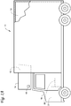
- Fig. 1A depicts a temperature-controlled straight truck 11 that includes a conditioned load space 12 for carrying cargo.
- a transport refrigeration unit (TRU) 14 is mounted to a front wall 16 of the load space 12.
- the TRU 14 is controlled via a controller 15 to provide temperature control within the load space 12.
- the truck 11 further includes a vehicle power bay 18, which houses a prime mover 21, such as a combustion engine (e.g., diesel engine, etc.), that provides power to move the truck 11 and to operate the TRU 14.
- the prime mover 21 can work in combination with an optional machine 22 (e.g., an alternator) to operate the TRU 14.
- the TRU 14 includes a vehicle electrical system (see Fig. 2 ).
- the truck 11 can be a hybrid vehicle that is powered by the prime mover 21 in combination with a battery power source or can be an electrically driven truck in which the prime mover 21 is replaced with an electric power source (e.g., a battery power source).
- a battery power source e.g., a battery power source
- Fig. 1A illustrates a temperature-controlled straight truck 11
- a container such as a container on a flat car, an intermodal container, etc.
- box car or other similar transport unit.
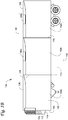
- Fig. 1B illustrates one embodiment of a MTRS 100 for a TU 125 that can be towed, for example, by a tractor (not shown).
- the MTRS 100 includes a TRU 110 that provides environmental control (e.g. temperature, humidity, air quality, etc.) within an internal space 150 of the TU 125.
- the MTRS 100 also includes a MTRS controller 170 and one or more sensors (e.g., Hall effect sensors, current transducers, etc.) (see Fig. 2 ) that are configured to measure one or more parameters (e.g., ambient temperature, compressor suction pressure, compressor discharge pressure, supply air temperature, return air temperature, humidity, etc.) of the MTRS 100 and communicate parameter data to the MTRS controller 170.
- sensors e.g., Hall effect sensors, current transducers, etc.
- the MTRS 100 is powered by a power module 112.
- the TRU 110 is disposed on a front wall 130 of the TU 125. In other embodiments, it will be appreciated that the TRU 110 can be disposed, for example, on a rooftop 126 or another wall of the TU 125.
- the MTRS 100 can include an undermount unit 113.
- the undermount unit 113 can be a TRU that can also provide environmental control (e.g. temperature, humidity, air quality, etc.) within the internal space 150 of the TU 125.
- the undermount unit 113 can work in combination with the TRU 110 to provide redundancy or can replace the TRU 110.
- the undermount unit 113 can be a power module that includes, for example, a generator that can help power the TRU 110.
- the programmable MTRS Controller 170 may comprise a single integrated control unit or may comprise a distributed network of TRS control elements. The number of distributed control elements in a given network can depend upon the particular application of the principles described herein.
- the MTRS controller 170 is configured to control operation of the MTRS 100.
- the power module 112 is disposed in the TRU 110. In other embodiments, the power module 112 can be separate from the TRU 110. Also, in some embodiments, the power module 112 can include two or more different power sources disposed within or outside of the TRU 110. In some embodiments, the power module 112 can include one or more of a prime mover, a battery, an alternator, a generator, a solar panel, a fuel cell, etc. Also, the prime mover can be a combustion engine or a microturbine engine and can operate as a two speed prime mover, a variable speed prime mover, etc.
- the power module 112 can provide power to, for example, the MTRS Controller 170, a compressor (not shown), a plurality of DC (Direct Current) components (not shown), a power management unit (see Fig. 2 ), etc.
- the DC components can be accessories or components of the MTRS 100 that require DC power to operate. Examples of the DC components can include, for example, DC fan motor(s) for a condenser fan or an evaporator blower (e.g., an Electrically Commutated Motor (ECM), a Brushless DC Motor (BLDC), etc.), a fuel pump, a drain tube heater, solenoid valves (e.g., controller pulsed control valves), etc.
- ECM Electrically Commutated Motor
- BLDC Brushless DC Motor
- the power module 112 can include a DC power source (not shown) for providing DC electrical power to the plurality of DC components (not shown), the power management unit (see Fig. 2 ), etc.
- the DC power source can receive mechanical and/or electrical power from, for example, a utility power source (e.g., Utility power, etc.), a prime mover (e.g., a combustion engine such as a diesel engine, etc.) coupled with a generator machine (e.g., a belt-driven alternator, a direct drive generator, etc.), etc.
- a utility power source e.g., Utility power, etc.
- a prime mover e.g., a combustion engine such as a diesel engine, etc.
- a generator machine e.g., a belt-driven alternator, a direct drive generator, etc.
- the bi-directional voltage converter can be a bi-directional multi-battery voltage converter.
- the internal space 150 can be divided into a plurality of zones 152.
- the term "zone” means a part of an area of the internal space 150 separated by walls 175. It will be appreciated that the invention disclosed herein can also be used in a single zone TRS.
- the MTRS 100 for the TU 125 includes the TRU 110 and a plurality of remote evaporator units 180.
- an HVAC system can be powered by an Auxiliary Power Unit (APU, see Figs. 1C and 1D ).
- the APU can be operated when a main prime mover of the TU 125 is turned off such as, for example, when a driver parks the TU 125 for an extended period of time to rest.
- the APU can provide, for example, power to operate a secondary HVAC system to provide conditioned air to a cabin of the TU 125.
- the APU can also provide power to operate cabin accessories within the cabin such as a television, a microwave, a coffee maker, a refrigerator, etc.
- the APU can be a mechanically driven APU (e.g., prime mover driven) or an electrically driven APU (e.g., battery driven).
- the tractor includes a vehicle electrical system (see Fig. 2 ) for supplying electrical power to the electrical loads of the tractor, the MTRS 100, and/or the TU 125.
- a vehicle electrical system see Fig. 2 for supplying electrical power to the electrical loads of the tractor, the MTRS 100, and/or the TU 125.
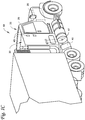
- Fig. 1C illustrates a vehicle 10 according to one embodiment.
- the vehicle 10 is a semi-tractor that is used to transport cargo stored in a cargo compartment (e.g., a container, a trailer, etc.) to one or more destinations.
- a cargo compartment e.g., a container, a trailer, etc.
- vehicle shall be used to represent all such tractors and trucks, and shall not be construed to limit the invention's application solely to a tractor in a tractor-trailer combination.
- the vehicle 10 can be, for example, a straight truck, van, etc.
- the vehicle 10 includes a primary power source 20, a cabin 25 defining a sleeping portion 30 and a driving portion 35, an APU 40, and a plurality of vehicle accessory components 45 (e.g., electronic communication devices, cabin lights, a primary and/or secondary HVAC system, primary and/or secondary HVAC fan(s), sunshade(s) for a window/windshield of the vehicle 10, cabin accessories, etc.).
- vehicle accessory components 45 e.g., electronic communication devices, cabin lights, a primary and/or secondary HVAC system, primary and/or secondary HVAC fan(s), sunshade(s) for a window/windshield of the vehicle 10, cabin accessories, etc.
- the cabin 25 can be accessible via a driver side door (not shown) and a passenger side door 32.
- the cabin 25 can include a primary HVAC system (not shown) that can be configured to provide conditioned air within driving portion 35 and potentially the entire cabin 25, and a secondary HVAC system (not shown) for providing conditioned air within the sleeping portion 30 of the cabin 25.
- the cabin 25 can also include a plurality of cabin accessories (not shown).
- cabin accessories can include, for example, a refrigerator, a television, a video game console, a microwave, device charging station(s), a continuous positive airway pressure (CPAP) machine, a coffee maker, a secondary HVAC system for providing conditioned air to the sleeping portion 30.
- CPAP continuous positive airway pressure
- the primary power source 20 can provide sufficient power to operate (e.g., drive) the vehicle 10 and any of the plurality of vehicle accessory components 45 and cabin accessory components 47.
- the primary power source 20 can also provide power to the primary HVAC system and the secondary HVAC system.
- the primary power source can be a prime mover such as, for example, a combustion engine (e.g., a diesel engine, etc.).
- the APU 40 is a secondary power unit for the vehicle 10 when the primary power source 20 is unavailable.
- the APU 40 can be configured to provide power to one or more of the vehicle accessory components, the cabin accessories, the primary HVAC system and the secondary HVAC system.
- the APU 40 can be an electric powered APU.
- the APU 40 can be a prime mover powered APU.
- the APU 40 can be attached to the vehicle 10 using any attachment method.
- the APU 40 can be turned on (i.e., activated) or off (i.e., deactivated) by an occupant (e.g., driver or passenger) of the vehicle 10.
- the APU 40 generally does not provide sufficient power for operating (e.g., driving) the vehicle 10.
- the APU 40 can be controlled by an APU controller 41.
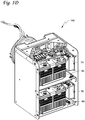
- Fig. 1D illustrates an electric APU 140 that can be used with a vehicle (e.g., the vehicle 10 shown in Fig. 1C ), according to one embodiment.
- the APU 140 includes a plurality of energy storage elements 60 each of which is coupled to one of a plurality of converters 70.
- the converters 70 can provide electric power (e.g., AC or DC power) generated by the APU 140 to one or more vehicle accessory components, cabin accessory components, a primary HVAC system, and a secondary HVAC system.
- a secondary HVAC system can provide conditioned air to a sleeping portion of a vehicle cabin (e.g., the sleeping portion 30 of the cabin 25 shown in Fig. 1C ).
- the energy storage elements 60 can be, for example, battery packs, fuel cells, etc.
- the APU 140 can be turned on or off by an occupant (e.g., driver or passenger) of the vehicle.
- the occupant can turn on the APU 140 to provide power stored in the energy storage elements 60 when a primary power source of the vehicle is turned off.
- the embodiments described herein can also be used with a prime mover powered APU.
- the APU (e.g., the APU 40 as shown in Fig. 1C and/or the APU 140 as shown in Fig. 1D ) includes a vehicle electrical system (see Fig. 2 ).
- Fig. 1E depicts a temperature-controlled van 80 that includes a conditioned load space 82 (or internal space) for carrying cargo.
- a transport refrigeration unit (TRU) 85 is mounted to a rooftop 84 of the load space 82.
- the TRU 85 is controlled via a controller 83 to provide temperature control within the load space 82.
- the van 80 further includes a vehicle power bay 86, which houses a prime mover 87, such as a combustion engine (e.g., diesel engine, etc.), that provides power to move the van 80 and to operate the TRU 85.
- the prime mover 87 can work in combination with an optional machine 88 (e.g., an alternator) to operate the TRU 85.
- an optional machine 88 e.g., an alternator
- the TRU 85 includes a vehicle electrical system (see Fig. 2 ).
- the van 80 can be a hybrid vehicle that is powered by the prime mover 87 in combination with a battery power source or can be an electrically driven truck in which the prime mover 87 is replaced with an electric power source (e.g., a battery power source).
- Fig. 2 illustrates a block diagram schematic of one embodiment of a vehicle electrical system 200.
- the vehicle electrical system 200 can be provided, for example, in the TRU 14 shown in Fig. 1A to supply electrical power to the TRU 14. Also, the vehicle electrical system 200 can be provided to supply electrical power to the electrical loads of the tractor, the MTRS 100, and/or the TU 125 shown in Fig. 1B .
- the vehicle electrical system 200 can also be provided as part of an APU (e.g., the APU 40 shown in Fig. 1C and/or the APU 140 shown in Fig. 1D ) to supply electrical power to one or more loads connected to the APU.
- the vehicle electrical system 200 shown in Fig. 2 is configured to operate with a prime mover powered vehicle. However, it will be appreciated that the vehicle electrical system 200 can also be configured to operate with an electric vehicle powered by an energy storage device (e.g., one or more batteries) and/or a hybrid vehicle powered by a combination of a prime mover and an energy storage
- the vehicle electrical system 200 includes a DC regulated bus 202 electrically connecting a vehicle power network 204, an auxiliary power network 206, a utility power network 208, a bi-directional voltage converter 240 and a transport climate control load network 212.
- the DC regulated bus 202 can be a 12 volts DC regulated bus.
- "regulated" is a term of art.
- a regulated power supply can convert unregulated AC (Alternating Current) supply into a constant DC, with the help of a rectifier (or an AC-DC converter, or the like), and can supply a stable voltage (or current in some situations), to a circuit or device that need to be operated within certain power supply limits.
- the voltage provided to the bus can vary, for example, between about 11 volts to about 15 volts.
- the DC regulated bus 202 can travel from a vehicle power bay to a cab of the vehicle, to a TRU, and/or to a APU.
- the vehicle electrical system 200 can manage and regulate energy from one or more energy sources from the vehicle power network 204, the auxiliary power network 206 and/or the utility power network 208 to the transport climate control load network 212 via the bi-directional voltage converter 240.
- the one or more energy sources can include a vehicle battery 210 and an vehicle alternator 205 via the vehicle power network 204, a utility power 220 (also referred to as a shore power source) via the utility power network 208, and/or one or more auxiliary batteries 230 via the auxiliary power network 206.
- the vehicle electrical system 200 is configured to supply energy to one or more loads from the transport climate control load network 212.
- the loads can be, for example, a compressor 255, one or more evaporator blowers 265, one or more condenser fans 270, a heater 275, and a controller 260 of an transport climate control system.
- the vehicle power network 204 includes the vehicle battery 210, the vehicle alternator 205 and a vehicle isolator 215 disposed between the vehicle alternator 205 and the vehicle battery 210 at one end and the DC regulated bus 202 at a second end.
- the vehicle battery 210 can be used, for example, for starting a vehicle prime mover, running lights, powering vehicle accessory components, etc. In some embodiments, the vehicle battery 210 can also be used to power components of the transport climate control load network 208.
- the vehicle battery 210 and the vehicle alternator 205 are connected to the DC regulated bus 202 via a vehicle isolator 215.
- the vehicle isolator 215 can be a switch controlled by the controller 260 that isolates the bi-directional voltage converter 240 from receiving energy from the vehicle power network 204.
- the vehicle alternator 205 can be an electrical alternator that can provide AC power to the vehicle.
- the vehicle alternator 205 can include a rectifier or an AC-DC converter (not shown) that rectifies or converts the AC power to a DC power.
- the vehicle alternator 205 is connected to the DC regulated bus 202 via the vehicle isolator 215.
- the vehicle alternator 205 can provide the rectified or converted DC power (for example, 12V) to the DC regulated bus 202.
- Electric vehicles can include a motor generator and a high voltage (e.g., in a range between 60V and 1500V; for example 400V, 800V, etc.) DC battery to run the vehicle. Electric vehicles can also provide a relatively high voltage (e.g., 400V, 800V, etc.) DC power source (e.g., a battery pack, a rechargeable energy storage system (RESS), etc.). Electric vehicles can include one or more DC-DC converters (e.g., two DC-DC convertors) to convert the relatively high voltage (e.g., 400V, 800V, etc.) to a low voltage (e.g., in a range between 0V and 60V; for example 12V).
- a relatively high voltage e.g., 400V, 800V, etc.
- a low voltage e.g., in a range between 0V and 60V; for example 12V.
- the vehicle alternator 205 can be replaced with a DC-DC converter having similar parameters as the vehicle alternator 205 in order to be able to provide a low voltage to the DC regulated bus 202 and power one or more loads of the transport climate control load network 212.
- the converted low voltage e.g. 12V
- vehicle accessory components e.g., electronic communication devices, cabin lights, a primary and/or secondary HVAC system, primary and/or secondary HVAC fan(s), sunshade(s) for a window/windshield of the vehicle 10, cabin accessories, etc.
- the converted low voltage (e.g. 12V) can be provided to the DC regulated bus 202 for powering the transport climate control load network 212.
- an electric vehicle can provide for example, 7kW-Hour energy from a 45kW-Hour storage of the vehicle power network 204 to run the transport climate control load network 212.
- a low voltage e.g., 12V
- Embodiments disclosed herein can use take off power (e.g., electric power take off or ePTO) from the low voltage (for example, 12V) system for loads such as vehicle accessory components and/or the transport climate control load network 212.
- the high voltage power can provide power for driving the vehicle (e.g., transmission power take off) and the embodiments disclosed herein may not take electric power from the high voltage system.
- an alternator such as the vehicle alternator 205
- a low voltage DC power source that can provide a low voltage (e.g., 12V) to the DC regulated bus 202.
- any type of power source from the vehicle that can provide power to the vehicle electrical system 200 can be part of the vehicle power network 204.
- This can include, for example, the vehicle alternator 205, the vehicle battery 210, a RESS, a generator, an axle-mounted generator, a power take off (PTO) device or ePTO device with an auxiliary converter, etc.
- PTO power take off
- a voltage sensor (not shown) can be provided in the vehicle power network 204 to monitor a vehicle voltage provided to the DC regulated bus 202.
- a current sensor (not shown) can be provided in series with the vehicle isolator 215 to monitor the current to and from the auxiliary power network 206.
- the utility power network 208 includes the AC-DC converter 225.
- a utility power (e.g., Utility power, etc.) 220 can be connected to the AC-DC converter 225 to provide AC power input to the AC-DC converter 225.
- the AC-DC converter 225 converts the AC power from the utility power 220 and provides converted DC power to the DC regulated bus 202.
- the converted DC power from the AC-DC converter 225 to the DC regulated bus 202 can be, for example, 12 volts and 84 amps. While Fig. 2 shows a single AC-DC converter 225, it is appreciated that in other embodiments the vehicle electrical system 200 can includes two or more AC-DC converters.
- each of the AC-DC converters can be connected to the utility power 220 to provide additional power capacity to the vehicle electrical system 200.
- each of the AC-DC converters can provide different amounts of power. In some embodiments, each of the AC-DC converters can provide the same amount of power.
- the auxiliary power network 206 includes an optional auxiliary battery system 230 and two auxiliary power on/off switches 235 disposed between the auxiliary battery system 230 and the DC regulated bus 202.
- the auxiliary power network 206 can be part of the transport climate control system and potentially housed within a transport refrigeration unit.
- the auxiliary power network 206 can be external to the transport climate control system and part of the vehicle power network 204.
- the auxiliary power network 206 can be external to the transport climate control system and external to the vehicle power network 204.
- the auxiliary battery system 230 can include a one or more auxiliary batteries (also referred to as hold-over batteries).
- the auxiliary battery system 230 can include two auxiliary batteries (not shown).
- Each of the auxiliary batteries can also be connected to the DC regulated bus 202 via the bi-directional voltage converter 240.
- each of the auxiliary batteries can bypass the bi-directional voltage converter 240 and connect to the DC regulated bus 202 via one of the auxiliary power on/off switches 235.
- the auxiliary battery system 230 can provide sufficient energy to power the transport climate control load network 212 by itself.
- Each of the auxiliary power on/off switches 235 can be controlled by the controller 260.
- the bi-directional voltage converter 240 is configured to transfer power from one of the vehicle power network 204, the utility power network 208 and/or the auxiliary power network 206 to the transport climate control load network 212.
- the bi-directional voltage converter 240 can be part of an energy management module (e.g., a smart charge module (SCM), etc.).
- the bi-directional voltage converter 240 can transfer power from the vehicle power network 204 and/or the utility power network 208 to charge one or more auxiliary batteries of the auxiliary battery system 230.
- the bi-directional voltage converter 240 can control current flow along the DC regulated bus 202.
- the vehicle electrical system 200 can include two or more bi-directional voltage converters 240 each of which is part of a separate SMC.
- the energy management module can be a DC-DC charger.
- the bi-directional voltage converter 240 can step-down (buck) and step-up (boost) voltage for power being sent from the vehicle power network 204 and/or the utility power network 208 to the bi-directional voltage converter 240, and from the bi-directional voltage converter 240 to the vehicle power network 204 and/or the utility power network 208. Accordingly, the bi-directional voltage converter 240 can control current direction and current amount along the DC regulated bus 202.
- the vehicle electrical system 200 is controlled by the controller 260.
- the controller 260 can be, for example, the TRS controller 15 shown in Fig. 1A , the MTRS controller 170 of Fig. 1B , or the APU controller 41.
- a remote controller 280 can be connected to the controller 260 wirelessly (e.g., Bluetooth, ZigBee, etc.) or via wire (e.g., a communication link such as a RS485 communication link).
- the remote controller 280 can be located in a cab of the vehicle and can be controlled by a user, for example, a driver.
- the remote controller 280 can be used by a user to communicate the user's settings for components of the transport climate control load network 212 to the controller 260.
- Components of the transport climate control load network 212 can be, for example, part of a TRU that is mounted to the body of the vehicle (for example, truck). In some embodiments, the TRU can be above the cab of the truck. In another embodiment, the TRU can be on the top of the TU (for example, a top of a box where the external condensers are located).
- the transport climate control load network 212 includes a Compressor Drive Module (CDM) 250 that drives the compressor 255, one or more evaporator blowers 265, one or more condenser fans 270, the heater 275, and the controller 260.
- CDM Compressor Drive Module
- the DC regulated bus 202 is connected to and powers each of the CDM 250, the one or more evaporator blowers 265, the one or more condenser fans 270, the heater 275, and the controller 260. It will be appreciated that the CDM 250 and the compressor 255 can require the most power of the various loads of the transport climate control load network 212.
- the CDM 250 is configured to boost power from the DC regulated bus 202 and converts the power to AC power to drive the compressor 255.
- the CDM 250 can convert the low voltage DC power (for example, 12V) from the DC regulated bus 202 and provide, for example, 240V AC power to drive the compressor 255.
- the CDM 250 drives the compressor 255 to meet demand of the transport climate control system.
- the CDM 250 can cause the vehicle voltage to droop.
- the CDM 250 includes a DC-DC-AC converter in which the CDM 250 boosts the voltage from the DC regulated bus to a higher DC voltage and then converts the higher DC voltage to an AC voltage.
- the utility power 220 can be connected directly to the compressor 255 and provide power to drive the compressor 255 thereby bypassing the CDM 250.
- the CDM 250 can be used as an AC-DC converter and convert power received from the utility power 220 into DC power that can be provided by the CDM 250 to the DC regulated bus 202.
- the compressor 255 can be a variable speed compressor. In some embodiments, the compressor 255 can require, for example, 1KW of power to operate. In some embodiments, the one or more evaporator blowers 265 can require, for example, 100W of power to operate. In some embodiments, the one or more condenser fans 270 can require, for example, 130W of power to operate. In some embodiments, the heater 275 can require, for example, 1200W of power to operate. Also, in some embodiments, the heater 275 can be configured to receive power from the CDM 250.
- the compressor 255 and/or the heater 275 When the compressor 255 and/or the heater 275 are powered directly by the utility power 220, the compressor 255 and/or the heater 275 can be turned on and off (e.g., operate in a cycle sentry mode) in order to control the amount of cooling provided by the compressor 255 and/or the amount of heating provided by the heater 275.
- Fig. 3 illustrates a block diagram schematic of one embodiment of an energy management module 300.
- a vehicle power network 304 is electrically connected to the energy management module 300.
- the vehicle power network 304 can include one or more vehicle power sources such as, for example, a vehicle alternator (e.g., the vehicle alternator 205), a vehicle battery (e.g., the vehicle battery 210), etc.
- the energy management module 300 includes a bi-directional voltage converter 330.
- the bi-directional voltage converter 330 can be, for example, the bi-directional voltage converter 240 shown in Fig. 2 .
- the bi-directional voltage converter 330 can step-down (buck) and step-up (boost) voltage for power being sent from the vehicle power network 304 to the energy management module 300 and from the energy management module 300 to the vehicle power network 304. Accordingly, the bi-directional voltage converter 240 can control current direction and current amount along a DC regulated bus of a vehicle electrical system. Detailed descriptions on some embodiments of the bi-directional voltage converters can be found in, for example, U.S. Patent Nos.: 8,441,228 ; 8,541,905 ; 9,199,543 ; and 9,102,241 .
- the energy management module 300 includes a plurality of electric switches 310, 311, and 312.
- Each of the electric switches 310, 311, and 312 connects to (or disconnects from) a corresponding battery module 340, 341, and 342, respectively.
- the battery modules 340, 341, and 342 can be, for example, the auxiliary battery system 230 shown in Fig. 2 .
- the plurality of electric switches 310, 311, and 312 can be battery relays, electronic switches, etc.
- the electronic switches 310, 311, and 312 can be, for example, semiconductor (solid-state) switches such as SmartFET type switches.
- SmartFET type switches can be field-effect transistor (FET) switches that have smart built-in features such as diagnosis and protection capabilities.
- one or more of the battery modules 340, 341, and 342 can be an auxiliary battery used to power components of the transport climate control load network 212.
- the plurality of electric switches 310, 311, and 312 is configured to selectively connect one or more of the battery modules 340, 341, and 342 to the bi-directional voltage converter 330 so that at any given time, a subset of the battery modules 340, 341, and 342 connects to the bi-directional voltage converter 330.
- a controller (such as, for example, the controller 260 shown in Fig. 2 ) can be configured to control the plurality of electric switches 310, 311, 312 to selectively connect one or more of the battery modules 340, 341, and 342 to the bi-directional voltage converter 330.
- the plurality of electric switches 310, 311, and 312 can be configured to selectively connect more than one of the battery modules 340, 341, and 342 to the bi-directional voltage converter 330. It will also be appreciated that the plurality of electric switches 310, 311, and 312 can be a single battery relay or a single electronic switch that can be configured to selectively connect one or more of the plurality of battery modules 340, 341, and 342 to the bi-directional voltage converter 330.
- the bi-directional voltage converter 330 can connect to a system bus of a vehicle electrical system (such as, for example, the DC regulated bus 202 shown in Fig. 2 ) so that the selected battery module(s) 340, 341, and 342 can deliver power to electrical loads (such as, for example, components of the transport climate control load network 212 shown in Fig. 2 ) of the vehicle electrical system or can be charged by other power sources.
- a controller for example, the controller 260 shown in Fig.
- the bi-directional voltage converter 330 can control/switch a plurality of switches (not shown) of the bi-directional voltage converter 330 to control when and where the bi-directional voltage converter 330 directs current (for example, from the selected battery module 340, 341, 342 to the electrical loads in a discharging mode, or from other power source to the selected battery module 340, 341, 342 in a charging mode).
- the plurality of battery modules 340, 341, 342 of the energy management module 300 can charge (i.e., deliver power to) battery module(s) of another energy management module, or vice versa, to balance the power/energy stored in the battery module(s) of each energy management module.
- battery module(s) of different energy management modules can be combined/selected until the total power-delivery capacity (e.g. measured in peak amperes at a given voltage, such as 12 volts) is sufficient for supplying the power needs of the vehicle electrical system.
- the selected battery module(s) of different energy management modules can provide adequate power to the electrical loads of the vehicle electrical system based on the load draw.
- the selected battery module(s) of different energy management modules receive power from one or more power sources during a charge phase, and discharges power to the electrical loads of the vehicle electrical system during a discharge phase.
- a charge phase may occur when for example, a power source (such as, for example, the utility power network 208 shown in Fig. 2 ) provides power to the vehicle electrical system of the vehicle, and a discharge phase may occur when for example, the power source is not providing power to the vehicle electrical system of the vehicle (for example, when the prime mover (e.g., combustion engine) is stopped and utility power is unavailable).
- a power source such as, for example, the utility power network 208 shown in Fig. 2
- a discharge phase may occur when for example, the power source is not providing power to the vehicle electrical system of the vehicle (for example, when the prime mover (e.g., combustion engine) is stopped and utility power is unavailable).
- utility power 208 can be used to fill an energy shortfall when the vehicle cannot be run and a temperature control gap between the monitored temperature and a desired setpoint temperature of the internal space conditioned by the transport climate control system is large.
- a controller e.g., the controller 260 shown in Fig. 2
- the alert can instruct the driver to start the vehicle and run at a fast idle (e.g., raise an idle speed of a prime mover of the vehicle without raising a speed at which the vehicle is moving) or downshift a vehicle prime mover to operate at a higher prime mover RPM so as to prevent a failure of the transport climate control system and to prevent shedding or derating of loads of the transport climate control load network 212.
- the controller 260 can instruct the vehicle to start an automatic restart module to start the vehicle and run at a fast idle to prevent failure of the transport climate control system and to prevent shedding or derating of loads of the transport climate control load network 212.
- the controller 260 can instruct the vehicle to disable an auto start/stop system of the vehicle prime mover.
- the alert can be sent a time period (e.g., 1 to 5 minutes) before any action is taken or required.
- the bi-directional voltage converter 330 of the energy management module 300 can transfer power/energy between a power source and the selected battery module(s) 340, 341, and 342.
- the bi-directional voltage converter 330 is also referred to as a bi-directional multi-battery voltage converter.
- the bi-directional voltage converter 330 can include a control circuit (not shown). The control circuit can selectively energize one or more of the plurality of electric switches 310, 311, and 312 to connect the selected battery module(s) 340, 341, and 342 with the bi-directional voltage converter 330.
- the energy management module 300 can operate in one of three modes: a charge mode, a discharge mode, and a null mode.
- a charge mode the energy management module 300 can charge one or more of the battery modules 340, 341, and 342 using a power source (for example, the utility power 220 or the vehicle alternator 205 shown in Fig. 2 ).
- a discharge mode the energy management module 300 can deliver power from one or more of the battery modules 340, 341, and 342 to the electrical loads (for example, components of the transport climate control load network 212 shown in Fig. 2 ).
- the energy management module 300 In the null mode, the energy management module 300 is configured to prevent current from flowing between any of the battery module 340, 341, and 342 and the rest of the vehicle electrical system.
- the control circuit is controlled such that none of the battery modules 340, 341, and 342 are energized.
- the energy management module 300 operational modes can be determined by the controller (for example, the controller 260 shown in Fig. 2 ).
- the controller (for example, the controller 260 shown in Fig. 2 ) can switch the bi-directional voltage converter 330 ON (enabled) to draw current from a system bus of a vehicle electrical system or OFF (disabled) to prevent the bi-directional voltage converter 330 from drawing current.
- the bi-directional voltage converter 330 can direct current from one or more power sources to a selected battery module of the plurality of battery modules 340, 341, 342.
- the bi-directional voltage converter 330 When the bi-directional voltage converter 330 is switched ON in the discharging mode, the bi-directional voltage converter 330 can direct current from a selected battery module of the plurality of battery modules 340, 341, 342 to one or more electrical loads (e.g., components of the transport climate control load network 212 shown in Fig. 2 ). When the bi-directional voltage converter 330 is switched OFF, current can be prevented from flowing between the battery modules and the system bus via the bi-directional voltage converter 330.
- one or more electrical loads e.g., components of the transport climate control load network 212 shown in Fig. 2
- Fig. 4 illustrates a flowchart of one embodiment of a method 400 for managing energy to the transport climate control load network 212 from the vehicle electrical system 200.
- the method 400 begins at 405 whereby the controller 260 determines whether the utility power network 208 is connected to the utility power 220 and the utility power network 208 is permitted to receive power from the utility power 220.
- the utility power network 208 may be connected to the utility power 220 but not permitted to receive power from the utility power 220 when, for example, cost of power from the utility power 220 is too expensive, the use of utility power 220 by the vehicle electrical system 200 is being restricted, etc.
- the controller 260 can be configured to monitor an ignition of the vehicle, determine that the utility power network 208 is permitted to receive power from the utility power 220 when the utility power 220 is connected to the utility power network 208 and the ignition of the vehicle is on, and determine that the utility power network 208 is not permitted to receive power from the utility power 220 when the utility power 220 is not connected to the utility power network 208 or the ignition of the vehicle is off.
- the method 400 proceeds to 410. If the utility power network 208 is not connected to the utility power 220 or the utility power network 208 is not permitted to receive power from the utility power 220, the method 400 proceeds to 415.
- the vehicle electrical system 200 is operated with utility power.
- the AC-DC converter 225 converts the utility power 220 into DC power that is provided to the DC regulated bus 202.
- the controller 260 is configured to control the vehicle isolator 215 so as to prevent power from the vehicle power network 204 to be supplied to DC regulated bus 202.
- the controller 260 is also configured to control the auxiliary power on/off switches 235 so as to prevent the auxiliary battery system 230 from supplying power to the DC regulated bus 202.
- the vehicle electrical system 200 can provide power to the transport climate control load network 212.
- the controller 260 can also determine whether one or more of the auxiliary batteries of the auxiliary battery system 230 require charging.
- the controller 260 can be configured to operate the bi-directional voltage converter 240 in the charge mode so as to charge the one or more auxiliary batteries of the auxiliary battery system 230. If charging is not required, the controller 260 can be configured to operate the bi-directional voltage converter 240 in the null mode. A method for charging the auxiliary battery system 230 is discussed below with respect to Fig. 5. The method 400 then proceeds back to 405.
- the controller 260 monitors a vehicle voltage or current provided by the vehicle power network 204 to the DC regulated bus 202.
- a voltage sensor (not shown) is disposed in the vehicle power network 204 to measure the vehicle voltage. The voltage sensor then sends the vehicle voltage measurement to the controller 260.
- a current sensor (not shown) can be disposed in the vehicle power network 204 to measure current coming into and out of the vehicle battery 210. In these embodiments, the current measurements can be sent to the controller 260 in lieu of the vehicle voltage measurement.
- the method 400 then proceeds to 420.
- the controller 260 determines whether the vehicle power network 204 has excess power capacity available based on the vehicle voltage (or optionally the vehicle current) provided by the vehicle power network 204 to the DC regulated bus 202.
- the vehicle electrical system 200 can have excess power capacity available when, for example, the vehicle is highway cruising with limited stops or idling. Accordingly, the vehicle alternator 205 is supplying sufficient power to power the transport climate control network 212 by itself and can also supply power to the bi-directional voltage converter 240 to charge one or more auxiliary batteries of the auxiliary battery system 230. In some embodiments, when the vehicle power network 204 has excess power capacity available, the vehicle alternator 205 can supply power to the DC regulated bus 202 without assistance of the vehicle battery 210.
- the controller 260 can determine that the vehicle power network 204 has excess power capacity available when the vehicle voltage is greater than an excess power capacity threshold. For example, when the DC regulated bus 202 is a 12 volt regulated bus, the controller 260 can determine that the vehicle power network 204 has excess power capacity available when the vehicle voltage provided by the vehicle power network 204 is greater than the excess power capacity threshold that is, for example, about 13.5 volts.
- the method 400 proceeds to 425. If the controller 260 determines that the vehicle power network 204 does not have excess power capacity available, the method 400 proceeds to 430.
- the vehicle electrical system 200 operates with excess power capacity.
- the controller 260 is configured to control the vehicle isolator 215 so as to allow power from the vehicle power network 204 to be supplied to DC regulated bus 202.
- the power from the vehicle power network 204 is from the vehicle alternator 205 without depleting charge of the vehicle battery 210.
- the controller 260 is also configured to control the auxiliary power on/off switches 235 so as to prevent the auxiliary battery system 230 from supplying power to the DC regulated bus 202.
- the vehicle electrical system 200 can provide power to the transport climate control load network 212 to operate the transport climate control system as desired.
- the controller 260 can also determine whether one or more of the auxiliary batteries of the auxiliary battery system 230 require charging. If charging is required, the controller 260 can be configured to operate the bi-directional voltage converter 240 in the charge mode so as to charge the one or more auxiliary batteries of the auxiliary battery system 230. If charging is not required, the controller 260 can be configured to operate the bi-voltage directional converter 240 in the null mode.
- the DC regulated bus 202 supplies required power to the transport climate control network 212 to operate the transport climate control system as desired and can supply any excess power available to the bi-directional voltage converter 240 to charge the auxiliary battery system 206. The method 400 then proceeds back to 405.
- the controller 260 determines whether the vehicle power network 204 has sufficient power capacity available based on the vehicle voltage provided by the vehicle power network 204 to the DC regulated bus 202.
- the vehicle electrical system 200 can have sufficient power capacity available when, for example, the vehicle is city driving with stops and idling that can reduce the amount of power available by the vehicle alternator 205. Accordingly, the vehicle alternator 205, with potentially the assistance of the vehicle battery 210, can supply sufficient power to power the transport climate control network 212 but potentially not enough to also supply power to the bi-directional voltage converter 240 to charge one or more auxiliary batteries of the auxiliary battery system 230.
- the vehicle alternator 205 supplies power to the DC regulated bus 202 with potentially the assistance of the vehicle battery 210, thereby depleting charge of the vehicle battery 210.
- the controller 260 can determine that the vehicle power network 204 has sufficient power capacity available when the vehicle voltage is within a sufficient power capacity threshold range. For example, when the DC regulated bus 202 is a 12 volt regulated bus, the controller 260 can determine that the vehicle power network 204 has sufficient power capacity available when the vehicle voltage provided by the vehicle power network 204 is within the sufficient power capacity threshold range that is, for example, between about 13 volts and 13.5 volts.
- the method 400 proceeds to 435. If the controller 260 determines that the vehicle power network 204 does not have sufficient power capacity available, the method 400 proceeds to 480.
- the vehicle electrical system 200 operates with sufficient power capacity.
- the controller 260 is configured to control the vehicle isolator 215 so as to allow power from the vehicle power network 204 to be supplied to the DC regulated bus 202.
- the power from the vehicle power network 204 is from the vehicle alternator 205 and the vehicle battery 210, thereby depleting charge of the vehicle battery 210.
- the controller 260 is also configured to control the auxiliary power on/off switches 235 so as to prevent the auxiliary battery system 230 from supplying power to the DC regulated bus 202.
- the vehicle electrical system 200 can provide power to the transport climate control load network 212 as desired by the transport climate control system.
- the controller 260 can be configured to operate the bi-directional voltage converter 240 in the null mode and prevent charging of the auxiliary battery system 230.
- the method 400 then proceeds to 440.
- the controller 260 monitors the power available capacity from the vehicle power network 204. This can occur when, for example, the vehicle is stopped or idling for a period of time and the load on the vehicle power network 204 is greater than can be provided by the vehicle power network 204.
- the controller 260 can monitor the power available capacity from the vehicle power network 204 by monitoring the vehicle voltage provided by the vehicle power network 204 to the DC regulated bus 202 and/or by monitoring the vehicle current passing from the vehicle power network 204 to the DC regulated bus 202.
- the controller 260 can monitor the power available capacity from the vehicle power network 204 by starting a timer.
- the timer can be set to a predetermined time period based on, for example, testing data of the vehicle electrical system 200.
- the controller 260 can monitor the power available capacity from the vehicle power network 204 by both monitoring the vehicle voltage (and/or vehicle current) and by starting the timer.
- the timer can be set based on user requirements and in order to provide hysteresis and prevent mode cycling to the method 400. For example, in some embodiments, the timer can be set to a number of minutes (e.g., a number between 1 to 5 minutes).
- Significant discharge of the vehicle battery 210 can be a predetermined charge value of the vehicle battery 210 that is based on, for example, cargo customer requirements, vehicle requirements, and/or governmental regulations. For example, significant discharge of the vehicle battery 210 may be a charge value set to ensure that the vehicle battery can start a prime mover of the vehicle when the vehicle is not running. The method 400 then proceeds to 445.
- the controller 260 determines whether the power available capacity has exceeded a capacity threshold.
- the capacity threshold can be a value that correlates with the battery power available capacity of the vehicle power network 204 and can be used to prevent, for example, significant discharge of the vehicle battery 210.
- the capacity threshold can be a vehicle voltage value and/or a vehicle current value.
- the capacity threshold can be a timer value.
- the controller 260 can use two capacity thresholds with the first capacity threshold being a vehicle voltage or current value and the second capacity threshold being a timer value.
- the controller 260 determines that the power available capacity monitored at 440 exceeds the capacity threshold, the method 400 proceeds back to 435.
- the controller 260 can determine that the power available capacity monitored at 440 exceeds the capacity threshold, when both the first capacity threshold and the second capacity threshold are exceeded. That is, the vehicle voltage value is greater than a vehicle voltage value threshold and the timer value has not been reached.
- the controller 260 determines that the power available capacity monitored at 440 does not exceed the capacity threshold, the method 400 proceeds to 455.
- the controller 260 can determine that the power available capacity monitored at 440 does not exceed the capacity threshold, when either the first capacity threshold or the second capacity threshold is exceeded. That is, the vehicle voltage value is less than or equal to a vehicle voltage threshold value or the timer value has been reached.
- the controller 260 determines whether the auxiliary battery system 230 is sufficiently charged. In some embodiments, the controller 260 can determine the charge state of the auxiliary battery system 230 from the bi-directional voltage converter 240. In some embodiments, the auxiliary battery system 230 can be sufficiently charged if the charge state is above a charge state threshold (e.g., 20%). If the charge state of the auxiliary battery system 230 is above the charge state threshold (i.e., the auxiliary battery system 230 is sufficiently charged), the method 400 proceeds to 450. If the charge state of the auxiliary battery system 230 is below the charge state threshold (i.e., the auxiliary battery system 230 is not sufficiently charged), the method 400 proceeds to 470.
- a charge state threshold e.g. 20%
- the controller 260 can also send an alert, for example, to the user (e.g., vehicle driver), the cargo customer, etc. that there may be an energy scarcity of the vehicle electrical system 200.
- the alert can be sent via a SMS message, an email, can be displayed to the vehicle driver via the remote controller 280, etc.
- the alert can instruct the driver to start the vehicle and run at a fast idle (e.g., raise an idle speed of a prime mover of the vehicle without raising a speed at which the vehicle is moving) or downshift a vehicle prime mover to operate at a higher prime mover RPM so as to prevent a failure of the transport climate control system and to prevent shedding or derating of loads of the transport climate control load network 212.
- the controller 260 can instruct the vehicle to start an automatic restart module to start the vehicle and run at a fast idle to prevent failure of the transport climate control system and to prevent shedding or derating of loads of the transport climate control load network 212.
- the controller 260 can instruct the vehicle to disable an auto start/stop system of the vehicle prime mover.
- the alert can be sent a time period (e.g., 1 to 5 minutes) before any action is taken or required.
- the controller 260 determines whether the vehicle power network 204 requires holdover assistance based on the vehicle voltage provided by the vehicle power network 204 to the DC regulated bus 202.
- the vehicle power network 204 can require holdover assistance when, for example, the vehicle alternator 205, with potentially the assistance of the vehicle battery 210, is not supplying sufficient power to power the transport climate control network 212.
- the vehicle alternator 205 supplies power to the DC regulated bus 202 with potentially the assistance of the vehicle battery 210, thereby depleting charge of the vehicle battery 210.
- the controller 260 can determine whether the vehicle power network requires holdover assistance when the vehicle voltage is within a holdover assistance threshold range.
- the controller 260 can determine that the vehicle power network 204 requires holdover assistance when the vehicle voltage provided by the vehicle power network 204 is within the holdover assistance threshold range that is, for example, between about 12 volts and 13 volts.
- the method 400 proceeds to 455. If the controller 260 determines that the vehicle power network 204 does not require holdover assistance, the method 400 proceeds to 460.
- the vehicle electrical system 200 operates with holdover assistance.
- the controller 260 is configured to control the vehicle isolator 215 so as to allow power from the vehicle power network 204 to be supplied to the DC regulated bus 202.
- the controller 260 is configured to control the auxiliary power on/off switches 235 so as to allow power from the auxiliary battery system 230 to be supplied to the to the DC regulated bus 202.
- the auxiliary battery system 230 can supplement the power provided by the vehicle power network 204 to ensure that the vehicle electrical system 200 can provide power to the transport climate control load network 212 as desired by the transport climate control system.
- the bi-directional voltage converter 240 can be set to a predetermined discharge voltage, for example, about 15V (or 14.2V that is closer to the nominal voltage the vehicle alternator 205 can provide).
- the bi-directional voltage converter 240 can run at a discharge mode, with a current limit of, for example, 40A or 20A or any suitable current required by the controller 260 to supplement the power from the vehicle power network 204. The method 400 then proceeds back to 405.
- the controller 260 determines whether the vehicle electrical system 200 should be exclusively powered by the auxiliary battery system 230 based on the vehicle electrical system power capacity available from the vehicle power network 204 to the DC regulated bus 202.
- the vehicle power network 204 can exclusively use power from the auxiliary battery system 230 to power the DC regulated bus 202 when, for example, use of the vehicle power network 204 would significantly discharge the vehicle battery 210 (such as when the vehicle is not running).
- one or more of the auxiliary batteries of the auxiliary battery system 230 supplies power to the DC regulated bus 202 and the vehicle power network 204 is prevented from supplying power to the DC regulated bus 202.
- the controller 260 can determine that the vehicle electrical system 200 should be exclusively powered by the auxiliary battery system 230 when the vehicle voltage is within an exclusive power threshold range. For example, when the DC regulated bus 202 is a 12 volt regulated bus, the controller 260 can determine that the vehicle electrical system 200 should be exclusively powered by the auxiliary battery system 230 when the vehicle voltage provided by the vehicle power network 204 is within the exclusive power threshold range that is, for example, between about 11.5 volts and 12 volts.
- the method 400 proceeds to 465. If the controller 260 determines that the vehicle electrical system 200 should not be exclusively powered by the auxiliary battery system 230, the method 400 proceeds to 470.
- the vehicle electrical system 200 is powered exclusively by the auxiliary battery system 230.
- the controller 260 is configured to control a range of operation of the vehicle isolator 215 so as to prevent power from the vehicle power network 204 to be supplied to the DC regulated bus 202.
- the controller 260 is configured to control the auxiliary power on/off switches 235 so as to allow power from the auxiliary battery system 230 to be supplied to the to the DC regulated bus 202.
- the auxiliary battery system 230 can provide sufficient power to ensure that the vehicle electrical system 200 can provide power to the transport climate control load network 212 as desired by the transport climate control system.
- the auxiliary battery system 230 can bypass the bi-directional voltage converter 240 to supply the necessary current so the CDM 250 can operate to meet the transport climate control network demand.
- the controller 260 can perform a load shedding process of the transport climate control load network 212 to reduce the amount of energy required by the DC regulated bus 202 and thereby the auxiliary power network 206 based on the amount of energy stored in the auxiliary battery system 230.
- the controller 260 can also send an alert, for example, to the user (e.g., vehicle driver), the cargo customer, etc. that there may be an energy scarcity of the vehicle electrical system 200.
- the alert can be sent via a SMS message, an email, can be displayed to the vehicle driver via the remote controller 280, etc.
- the alert can instruct the driver to start the vehicle and run at a fast idle (e.g., raise an idle speed of a prime mover of the vehicle without raising a speed at which the vehicle is moving) or downshift a vehicle prime mover to operate at a higher prime mover RPM so as to prevent a failure of the transport climate control system and to prevent shedding or derating of loads of the transport climate control load network 212.
- the controller 260 can instruct the vehicle to start an automatic restart module to start the vehicle and run at a fast idle to prevent failure of the transport climate control system and to prevent shedding or derating of loads of the transport climate control load network 212. In some embodiments, the controller 260 can instruct the vehicle to disable an auto start/stop system of the vehicle prime mover. In some embodiments, the alert can be sent a time period (e.g., 1 to 5 minutes) before any action is taken or required.
- the controller 260 determines whether the vehicle electrical system 200 should shut off power to the transport climate control load network 212 based on the vehicle voltage provided by vehicle power network 204. That is, the controller 260 determines whether the DC regulated bus 202 should be prevented from receiving energy from the vehicle power network 204, the auxiliary power network 206 and, when applicable, the utility power network 208 and sending said energy to the components of the transport climate control load network 212.
- the vehicle electrical system 200 should shut off power to the transport climate control load network 212 when, for example, there is insufficient power available to power the transport climate control network 212 or could harm operation of the vehicle.
- the controller 260 can determine that the vehicle electrical system 200 should shut off power to the transport climate control load network 212 when the vehicle voltage is less than a shut off threshold. For example, when the DC regulated bus 202 is a 12 volt regulated bus, the controller 260 can determine that the vehicle electrical system 200 should shut off power to the transport climate control load network 212 when the vehicle voltage provided by the vehicle power network 204 is less than the shut off threshold that is, for example, about 11.5 volts. If the controller 260 determines that the vehicle electrical system 200 should shut off power to the transport climate control load network 212, the method 400 proceeds to 475. If the controller 260 determines that the vehicle electrical system 200 does not have to shut off power to the transport climate control load network 212, the method 400 proceeds back to 405.
- a shut off threshold For example, when the DC regulated bus 202 is a 12 volt regulated bus, the controller 260 can determine that the vehicle electrical system 200 should shut off power to the transport climate control load network 212 when the vehicle voltage provided by the vehicle power network 204
- the controller 260 shuts off power from the vehicle electrical system 200 to the transport climate control load network 212.
- the controller 260 can be configured to control the vehicle isolator 215 so as to prevent power from the vehicle power network 204 to be supplied to the DC regulated bus 202.
- the controller 260 can be configured to control the auxiliary power on/off switches 235 so as to prevent power from the auxiliary battery system 230 to be supplied to the to the DC regulated bus 202.
- the controller 260 can also be configured to control the AC-DC converter 225 so as to prevent power from the utility power 220.
- the controller 260 can also send an alert, for example, to the user (e.g., vehicle driver), the cargo customer, etc.
- the alert can be sent via a SMS message, an email, can be displayed to the vehicle driver via the remote controller 280, etc.
- the alert can instruct the driver to start the vehicle and run at a fast idle (e.g., raise an idle speed of a prime mover of the vehicle without raising a speed at which the vehicle is moving) or downshift a vehicle prime mover to operate at a higher prime mover RPM so as to prevent a failure of the transport climate control system and to prevent shedding or derating of loads of the transport climate control load network 212.
- the controller 260 can instruct the vehicle to start an automatic restart module to start the vehicle and run at a fast idle to prevent failure of the transport climate control system and to prevent shedding or derating of loads of the transport climate control load network 212. In some embodiments, the controller 260 can instruct the vehicle to disable an auto start/stop system of the vehicle prime mover. In some embodiments, the alert can be sent a time period (e.g., 1 to 5 minutes) before any action is taken or required.
- the method 400 allows for energy management of the vehicle electrical system 200 as power from the vehicle power network 204 is decreasing. It will be appreciated that a similar methodology can be applied for energy management of the vehicle electrical system 200 as power from the vehicle power network 204 is increasing.
- the thresholds used for switching between power from the vehicle power network 204 and the auxiliary power network 206 can be the same or different as the thresholds provided in the method 400.
- the embodiments described herein can address two different but related issues.
- the first issue is related to variable loads.
- the vehicle alternator 205 has nominal power capacity.
- the electrical system of the vehicle has other loads such as the lights of the vehicle, etc.
- the power capacity of the vehicle alternator 205 is constant, as all the other loads (such as lights, fan, CD player, etc.) are switching on or off, the available power capacity for the transport climate control system is therefore not constant but variable.
- the second issue is related to the speed of the prime mover of the vehicle. Assuming the vehicle has a prime mover (e.g., a combustion engine such as a diesel engine, etc.), and the power capacity of the vehicle alternator 205 is driven or determined by the speed of the prime mover.
- a prime mover e.g., a combustion engine such as a diesel engine, etc.
- the power capacity that the vehicle (for example from the vehicle alternator 205) can provide drops. If the vehicle is running at a cruising speed, then the vehicle alternator 205 can generate required current for powering the transport climate control system). Part of the current provided by the vehicle (for example, the vehicle alternator 205) can be used to power the vehicle's other loads (such as lights, fan, CD player, etc.). The rest of the current can be drawn to the transport climate control system.
Abstract
Description
- This disclosure relates generally to energy management of a transport climate control system. More specifically, the disclosure relates to methods and systems for managing multiple energy sources for a transport climate control system.
- A transport climate control system can include, for example, a transport refrigeration system (TRS) and/or a heating, ventilation and air conditioning (HVAC) system. A TRS is generally used to control an environmental condition (e.g., temperature, humidity, air quality, and the like) within a cargo space of a transport unit (e.g., a truck, a container (such as a container on a flat car, an intermodal container, etc.), a box car, a semi-tractor, a bus, or other similar transport unit). The TRS can maintain environmental condition(s) of the cargo space to maintain cargo (e.g., produce, frozen foods, pharmaceuticals, etc.) In some embodiments, the transport unit can include a HVAC system to control a climate within a passenger space of the vehicle.
- This disclosure relates generally to energy management of a transport climate control system. More specifically, the disclosure relates to methods and systems for managing multiple energy sources for a transport climate control system.
- The embodiments described herein can maintain climate control of an internal space of a transport unit (e.g., cargo space, passenger space, etc.) when available energy capacity from one or more energy sources is inconsistent.
- This disclosure discloses a vehicle electrical system for managing loads and multiple energy sources to allow for management of electrical energy to provide power to a transport climate control system (also referred to as a HVAC-R system) even if the vehicle power source (for example, the prime mover) is off or unable to fully power the climate control system ("holdover"). In addition, the vehicle electrical system can provide a boost to the vehicle power using an auxiliary energy source (e.g., auxiliary battery) when the vehicle power (for example, from the prime mover) is insufficient.
- It will be appreciated that there can be multiple reasons for why the vehicle power source is limited. For example, the vehicle alternator might not be rated for the capacity needed for the loads. Another example is that the vehicle is slowing down (i.e., the vehicle is not running a full speed), and thus the vehicle alternator is not provided by the vehicle a full capacity (for example, the vehicle alternator is provided with 70% or 65% of the rated capacity). For example, the vehicle alternator at 100A can only provide 70A or 65A as the vehicle is slowing down. For the vehicle equipped with auto start-stop system (for example, to comply with the EU emission standard), the vehicle can shut down completely when the vehicle comes to a standstill stop (i.e., the vehicle alternator provides no current).
- Regulations to reduce emissions (e.g., particulate matter emissions, nitrogen oxide emissions, noise emissions, etc.), for example, from a vehicle prime mover (e.g.., a combustion engine such as a diesel engine, etc.), have led to components within the vehicle being electrically driven and the addition of emission reducing components (e.g., emission control devices, an auto start-stop system, etc.) in the space between the vehicle alternator and the prime mover within a vehicle power bay. The auto start-stop system can shut the prime mover off (i.e., the prime mover is not running) when, for example, the vehicle stops at a traffic light, stops at a store, etc. Accordingly, the amount of space between the vehicle alternator and the prime mover in the vehicle power bay that is available for other components is shrinking. For example, this reduced space can make it difficult to provide a separate compressor coupled to (or tied to, mounted to) the prime mover in the vehicle power bay to provide for high cooling power load and supplement a transport climate control system.
- The embodiments described herein can provide a transport climate control system that can be electrically driven by the power (for example, a 12V DC power) from the vehicle alternator. Also, the embodiments described herein can help to ensure that power for supply loads (e.g., the transport climate control system) is available as required. In particular, the embodiments described herein can ensure that the transport climate control system always has required power, by means of controlled hardware and power management algorithms to optimize vehicle power input, and by utilizing an attached auxiliary energy storage when necessary. The embodiments described herein can effectively manage multiple power sources and manage and optimize different input and output of the power.
- Also, the embodiments described herein can provide climate control within an internal space using a compressor that is disposed outside of the vehicle power bay and is driven by an electric drive. This can prevent the need for a compressor in the vehicle power bay and thereby increase the amount of space available in the vehicle power bay and can allow the separate compressor to operate even when the vehicle prime mover off.
- In one embodiment, a method for managing energy to a transport climate control system from a vehicle electrical system is provided. The vehicle electrical system includes a vehicle power network and an auxiliary power network connected to a transport climate control load network via a DC regulated bus. The method includes monitoring a vehicle voltage of the vehicle power network. The method also includes a controller determining whether the vehicle power network has sufficient power capacity available and whether the vehicle power network requires holdover assistance based on the vehicle voltage. Also, the method includes the DC regulated bus sending vehicle power energy generated by the vehicle power network to the transport climate control load network without assistance of the auxiliary power network when the controller determines that the vehicle power network has sufficient power capacity available. Further, the method includes the DC regulated bus sending the vehicle power energy generated by the vehicle power network and auxiliary power energy stored by the auxiliary power network to the transport climate control load network when the controller determines that the vehicle power network requires holdover assistance.
- In another embodiment, a vehicle electrical system for managing energy to a transport climate control system is provided. The vehicle electrical system includes a direct current (DC) regulated bus, a vehicle power network, an auxiliary power network, a transport climate control load network, and a controller. The vehicle power network is configured to generate power from a vehicle and provide the generated power to the DC regulated bus. The auxiliary power network includes an auxiliary battery system connected to the DC regulated bus. The auxiliary battery system is configured to store power and supply the stored power to the DC regulated bus. The transport climate control load network receives power from the DC regulated bus. The controller is configured to monitor a vehicle voltage of the vehicle power network, and determine whether the vehicle power network has sufficient power capacity available and whether the vehicle power network requires holdover assistance based on the vehicle voltage. The DC regulated bus is configured to send vehicle power energy generated by the vehicle power network to the transport climate control load network without assistance of the auxiliary power network when the controller determines that the vehicle power network has sufficient power capacity available. The DC regulated bus is configured to send vehicle power energy generated by the vehicle power network and auxiliary power energy stored by the auxiliary power network to the transport climate control load network when the controller determines that the vehicle power network requires holdover assistance
- References are made to the accompanying drawings that form a part of this disclosure and which illustrate embodiments in which the systems and methods described in this specification can be practiced.
-
Fig. 1A illustrates a side view of a truck with a front wall mounted vehicle powered transport refrigeration unit, according to one embodiment. -
Fig. 1B illustrates a schematic cross sectional side view of a refrigerated transport unit with a multi-temp transport refrigeration system, according to one embodiment. -
Fig. 1C illustrates a perspective view of a vehicle with an APU, according to one embodiment. -
Fig. 1D illustrates a front perspective view of an APU, according to one embodiment. -
Fig. 1E illustrates a side view of a van with a roof mounted vehicle powered transport refrigeration unit, according to one embodiment. -
Fig. 2 illustrates a block diagram schematic of one embodiment of a vehicle electrical system of a climate control system, according to one embodiment. -
Fig. 3 illustrates a block diagram schematic of one embodiment of an Energy Management Module, according to one embodiment. -
Fig. 4 illustrates a flowchart of one embodiment of a method for managing energy to a transport climate control load network from a vehicle electrical system. - Like reference numbers represent like parts throughout.
- This disclosure relates generally to energy sources and loads management. More specifically, the disclosure relates to methods and systems for managing and controlling auxiliary electrical storage and loads for multiple energy sources for a climate control system.
- The embodiments described herein can be provided in, for example, a transport climate control system such as a TRS or MTRS for a transport unit (TU), an HVAC system for a vehicle, etc.
- As defined herein, "low voltage" refers Class A of the ISO 6469-3 in the automotive environment. In particular, a maximum working voltage of between 0V and 60V DC or between 0V and 30V AC.
- As defined herein, "high voltage" refers Class B of the ISO 6469-3 in the automotive environment. In particular, a maximum working voltage of between 60V and 1500V DC or between 30V and 1000V AC.
-
Fig. 1A depicts a temperature-controlledstraight truck 11 that includes a conditionedload space 12 for carrying cargo. A transport refrigeration unit (TRU) 14 is mounted to afront wall 16 of theload space 12. TheTRU 14 is controlled via acontroller 15 to provide temperature control within theload space 12. Thetruck 11 further includes avehicle power bay 18, which houses aprime mover 21, such as a combustion engine (e.g., diesel engine, etc.), that provides power to move thetruck 11 and to operate theTRU 14. In some embodiments, theprime mover 21 can work in combination with an optional machine 22 (e.g., an alternator) to operate theTRU 14. In one embodiment, theTRU 14 includes a vehicle electrical system (seeFig. 2 ). Also, in some embodiments, thetruck 11 can be a hybrid vehicle that is powered by theprime mover 21 in combination with a battery power source or can be an electrically driven truck in which theprime mover 21 is replaced with an electric power source (e.g., a battery power source). - While
Fig. 1A illustrates a temperature-controlledstraight truck 11, it will be appreciated that the embodiments described herein can also apply to any other type of transport unit including, but not limited to, a container (such as a container on a flat car, an intermodal container, etc.), a box car, or other similar transport unit. -
Fig. 1B illustrates one embodiment of aMTRS 100 for aTU 125 that can be towed, for example, by a tractor (not shown). TheMTRS 100 includes aTRU 110 that provides environmental control (e.g. temperature, humidity, air quality, etc.) within aninternal space 150 of theTU 125. TheMTRS 100 also includes aMTRS controller 170 and one or more sensors (e.g., Hall effect sensors, current transducers, etc.) (seeFig. 2 ) that are configured to measure one or more parameters (e.g., ambient temperature, compressor suction pressure, compressor discharge pressure, supply air temperature, return air temperature, humidity, etc.) of theMTRS 100 and communicate parameter data to theMTRS controller 170. TheMTRS 100 is powered by apower module 112. TheTRU 110 is disposed on afront wall 130 of theTU 125. In other embodiments, it will be appreciated that theTRU 110 can be disposed, for example, on arooftop 126 or another wall of theTU 125. - In some embodiments, the
MTRS 100 can include anundermount unit 113. In some embodiments, theundermount unit 113 can be a TRU that can also provide environmental control (e.g. temperature, humidity, air quality, etc.) within theinternal space 150 of theTU 125. Theundermount unit 113 can work in combination with theTRU 110 to provide redundancy or can replace theTRU 110. Also, in some embodiments, theundermount unit 113 can be a power module that includes, for example, a generator that can help power theTRU 110. - The
programmable MTRS Controller 170 may comprise a single integrated control unit or may comprise a distributed network of TRS control elements. The number of distributed control elements in a given network can depend upon the particular application of the principles described herein. TheMTRS controller 170 is configured to control operation of theMTRS 100. - As shown in
Fig. 1B , thepower module 112 is disposed in theTRU 110. In other embodiments, thepower module 112 can be separate from theTRU 110. Also, in some embodiments, thepower module 112 can include two or more different power sources disposed within or outside of theTRU 110. In some embodiments, thepower module 112 can include one or more of a prime mover, a battery, an alternator, a generator, a solar panel, a fuel cell, etc. Also, the prime mover can be a combustion engine or a microturbine engine and can operate as a two speed prime mover, a variable speed prime mover, etc. Thepower module 112 can provide power to, for example, theMTRS Controller 170, a compressor (not shown), a plurality of DC (Direct Current) components (not shown), a power management unit (seeFig. 2 ), etc. The DC components can be accessories or components of theMTRS 100 that require DC power to operate. Examples of the DC components can include, for example, DC fan motor(s) for a condenser fan or an evaporator blower (e.g., an Electrically Commutated Motor (ECM), a Brushless DC Motor (BLDC), etc.), a fuel pump, a drain tube heater, solenoid valves (e.g., controller pulsed control valves), etc. - The
power module 112 can include a DC power source (not shown) for providing DC electrical power to the plurality of DC components (not shown), the power management unit (seeFig. 2 ), etc. The DC power source can receive mechanical and/or electrical power from, for example, a utility power source (e.g., Utility power, etc.), a prime mover (e.g., a combustion engine such as a diesel engine, etc.) coupled with a generator machine (e.g., a belt-driven alternator, a direct drive generator, etc.), etc. For example, in some embodiments, mechanical energy generated by a diesel engine is converted into electrical energy via a generator machine. The electrical energy generated via the belt driven alternator is then converted into DC electrical power via, for example, a bi-directional voltage converter. The bi-directional voltage converter can be a bi-directional multi-battery voltage converter. - The
internal space 150 can be divided into a plurality ofzones 152. The term "zone" means a part of an area of theinternal space 150 separated bywalls 175. It will be appreciated that the invention disclosed herein can also be used in a single zone TRS. - The
MTRS 100 for theTU 125 includes theTRU 110 and a plurality ofremote evaporator units 180. In some embodiments, an HVAC system can be powered by an Auxiliary Power Unit (APU, seeFigs. 1C and1D ). The APU can be operated when a main prime mover of theTU 125 is turned off such as, for example, when a driver parks theTU 125 for an extended period of time to rest. The APU can provide, for example, power to operate a secondary HVAC system to provide conditioned air to a cabin of theTU 125. The APU can also provide power to operate cabin accessories within the cabin such as a television, a microwave, a coffee maker, a refrigerator, etc. The APU can be a mechanically driven APU (e.g., prime mover driven) or an electrically driven APU (e.g., battery driven). - The tractor includes a vehicle electrical system (see
Fig. 2 ) for supplying electrical power to the electrical loads of the tractor, theMTRS 100, and/or theTU 125. -
Fig. 1C illustrates avehicle 10 according to one embodiment. Thevehicle 10 is a semi-tractor that is used to transport cargo stored in a cargo compartment (e.g., a container, a trailer, etc.) to one or more destinations. Hereinafter, the term "vehicle" shall be used to represent all such tractors and trucks, and shall not be construed to limit the invention's application solely to a tractor in a tractor-trailer combination. In some embodiments, thevehicle 10 can be, for example, a straight truck, van, etc. - The
vehicle 10 includes aprimary power source 20, acabin 25 defining a sleepingportion 30 and a drivingportion 35, anAPU 40, and a plurality of vehicle accessory components 45 (e.g., electronic communication devices, cabin lights, a primary and/or secondary HVAC system, primary and/or secondary HVAC fan(s), sunshade(s) for a window/windshield of thevehicle 10, cabin accessories, etc.). Thecabin 25 can be accessible via a driver side door (not shown) and a passenger side door 32. Thecabin 25 can include a primary HVAC system (not shown) that can be configured to provide conditioned air within drivingportion 35 and potentially theentire cabin 25, and a secondary HVAC system (not shown) for providing conditioned air within the sleepingportion 30 of thecabin 25. Thecabin 25 can also include a plurality of cabin accessories (not shown). Examples of cabin accessories can include, for example, a refrigerator, a television, a video game console, a microwave, device charging station(s), a continuous positive airway pressure (CPAP) machine, a coffee maker, a secondary HVAC system for providing conditioned air to the sleepingportion 30. - The
primary power source 20 can provide sufficient power to operate (e.g., drive) thevehicle 10 and any of the plurality ofvehicle accessory components 45 andcabin accessory components 47. Theprimary power source 20 can also provide power to the primary HVAC system and the secondary HVAC system. In some embodiments, the primary power source can be a prime mover such as, for example, a combustion engine (e.g., a diesel engine, etc.). - The
APU 40 is a secondary power unit for thevehicle 10 when theprimary power source 20 is unavailable. When, for example, theprimary power source 20 is unavailable, theAPU 40 can be configured to provide power to one or more of the vehicle accessory components, the cabin accessories, the primary HVAC system and the secondary HVAC system. In some embodiments, theAPU 40 can be an electric powered APU. In other embodiments, theAPU 40 can be a prime mover powered APU. TheAPU 40 can be attached to thevehicle 10 using any attachment method. In some embodiments, theAPU 40 can be turned on (i.e., activated) or off (i.e., deactivated) by an occupant (e.g., driver or passenger) of thevehicle 10. TheAPU 40 generally does not provide sufficient power for operating (e.g., driving) thevehicle 10. TheAPU 40 can be controlled by an APU controller 41. -
Fig. 1D illustrates anelectric APU 140 that can be used with a vehicle (e.g., thevehicle 10 shown inFig. 1C ), according to one embodiment. TheAPU 140 includes a plurality ofenergy storage elements 60 each of which is coupled to one of a plurality ofconverters 70. Theconverters 70 can provide electric power (e.g., AC or DC power) generated by theAPU 140 to one or more vehicle accessory components, cabin accessory components, a primary HVAC system, and a secondary HVAC system. A secondary HVAC system can provide conditioned air to a sleeping portion of a vehicle cabin (e.g., the sleepingportion 30 of thecabin 25 shown inFig. 1C ). Theenergy storage elements 60 can be, for example, battery packs, fuel cells, etc. In some embodiments, theAPU 140 can be turned on or off by an occupant (e.g., driver or passenger) of the vehicle. For example, the occupant can turn on theAPU 140 to provide power stored in theenergy storage elements 60 when a primary power source of the vehicle is turned off. It will be appreciated that the embodiments described herein can also be used with a prime mover powered APU. - In some embodiments, the APU (e.g., the
APU 40 as shown inFig. 1C and/or theAPU 140 as shown inFig. 1D ) includes a vehicle electrical system (seeFig. 2 ). -
Fig. 1E depicts a temperature-controlledvan 80 that includes a conditioned load space 82 (or internal space) for carrying cargo. A transport refrigeration unit (TRU) 85 is mounted to arooftop 84 of theload space 82. TheTRU 85 is controlled via acontroller 83 to provide temperature control within theload space 82. Thevan 80 further includes avehicle power bay 86, which houses aprime mover 87, such as a combustion engine (e.g., diesel engine, etc.), that provides power to move thevan 80 and to operate theTRU 85. In some embodiments, theprime mover 87 can work in combination with an optional machine 88 (e.g., an alternator) to operate theTRU 85. In one embodiment, theTRU 85 includes a vehicle electrical system (seeFig. 2 ). Also, in some embodiments, thevan 80 can be a hybrid vehicle that is powered by theprime mover 87 in combination with a battery power source or can be an electrically driven truck in which theprime mover 87 is replaced with an electric power source (e.g., a battery power source). -
Fig. 2 illustrates a block diagram schematic of one embodiment of a vehicleelectrical system 200. The vehicleelectrical system 200 can be provided, for example, in theTRU 14 shown inFig. 1A to supply electrical power to theTRU 14. Also, the vehicleelectrical system 200 can be provided to supply electrical power to the electrical loads of the tractor, theMTRS 100, and/or theTU 125 shown inFig. 1B . The vehicleelectrical system 200 can also be provided as part of an APU (e.g., theAPU 40 shown inFig. 1C and/or theAPU 140 shown inFig. 1D ) to supply electrical power to one or more loads connected to the APU. The vehicleelectrical system 200 shown inFig. 2 is configured to operate with a prime mover powered vehicle. However, it will be appreciated that the vehicleelectrical system 200 can also be configured to operate with an electric vehicle powered by an energy storage device (e.g., one or more batteries) and/or a hybrid vehicle powered by a combination of a prime mover and an energy storage device. - As shown in
Fig. 2 , the vehicleelectrical system 200 includes a DCregulated bus 202 electrically connecting avehicle power network 204, anauxiliary power network 206, autility power network 208, abi-directional voltage converter 240 and a transport climatecontrol load network 212. In some embodiments, the DCregulated bus 202 can be a 12 volts DC regulated bus. It will be appreciated that "regulated" is a term of art. For example, a regulated power supply can convert unregulated AC (Alternating Current) supply into a constant DC, with the help of a rectifier (or an AC-DC converter, or the like), and can supply a stable voltage (or current in some situations), to a circuit or device that need to be operated within certain power supply limits. It will also be appreciated that on a 12 volt regulated bus, the voltage provided to the bus can vary, for example, between about 11 volts to about 15 volts. In some embodiments, the DCregulated bus 202 can travel from a vehicle power bay to a cab of the vehicle, to a TRU, and/or to a APU. - The vehicle
electrical system 200 can manage and regulate energy from one or more energy sources from thevehicle power network 204, theauxiliary power network 206 and/or theutility power network 208 to the transport climatecontrol load network 212 via thebi-directional voltage converter 240. The one or more energy sources can include avehicle battery 210 and anvehicle alternator 205 via thevehicle power network 204, a utility power 220 (also referred to as a shore power source) via theutility power network 208, and/or one or moreauxiliary batteries 230 via theauxiliary power network 206. Also, the vehicleelectrical system 200 is configured to supply energy to one or more loads from the transport climatecontrol load network 212. The loads can be, for example, acompressor 255, one ormore evaporator blowers 265, one ormore condenser fans 270, aheater 275, and acontroller 260 of an transport climate control system. - The
vehicle power network 204 includes thevehicle battery 210, thevehicle alternator 205 and avehicle isolator 215 disposed between thevehicle alternator 205 and thevehicle battery 210 at one end and the DCregulated bus 202 at a second end. Thevehicle battery 210 can be used, for example, for starting a vehicle prime mover, running lights, powering vehicle accessory components, etc. In some embodiments, thevehicle battery 210 can also be used to power components of the transport climatecontrol load network 208. Thevehicle battery 210 and thevehicle alternator 205 are connected to the DCregulated bus 202 via avehicle isolator 215. In one embodiment, thevehicle isolator 215 can be a switch controlled by thecontroller 260 that isolates thebi-directional voltage converter 240 from receiving energy from thevehicle power network 204. - The
vehicle alternator 205 can be an electrical alternator that can provide AC power to the vehicle. In some embodiments, thevehicle alternator 205 can include a rectifier or an AC-DC converter (not shown) that rectifies or converts the AC power to a DC power. Thevehicle alternator 205 is connected to the DCregulated bus 202 via thevehicle isolator 215. Thevehicle alternator 205 can provide the rectified or converted DC power (for example, 12V) to the DCregulated bus 202. - It will be appreciated that in electric vehicles, there may be no alternator. Electric vehicles can include a motor generator and a high voltage (e.g., in a range between 60V and 1500V; for example 400V, 800V, etc.) DC battery to run the vehicle. Electric vehicles can also provide a relatively high voltage (e.g., 400V, 800V, etc.) DC power source (e.g., a battery pack, a rechargeable energy storage system (RESS), etc.). Electric vehicles can include one or more DC-DC converters (e.g., two DC-DC convertors) to convert the relatively high voltage (e.g., 400V, 800V, etc.) to a low voltage (e.g., in a range between 0V and 60V; for example 12V). That is, the
vehicle alternator 205 can be replaced with a DC-DC converter having similar parameters as thevehicle alternator 205 in order to be able to provide a low voltage to the DCregulated bus 202 and power one or more loads of the transport climatecontrol load network 212. The converted low voltage (e.g. 12V) can be used to power vehicle accessory components (e.g., electronic communication devices, cabin lights, a primary and/or secondary HVAC system, primary and/or secondary HVAC fan(s), sunshade(s) for a window/windshield of thevehicle 10, cabin accessories, etc.). In some embodiments, the converted low voltage (e.g. 12V) can be provided to the DCregulated bus 202 for powering the transport climatecontrol load network 212. In some embodiments, an electric vehicle can provide for example, 7kW-Hour energy from a 45kW-Hour storage of thevehicle power network 204 to run the transport climatecontrol load network 212. It will be appreciated that the embodiments disclosed herein is directed to a low voltage (e.g., 12V) system. Embodiments disclosed herein can use take off power (e.g., electric power take off or ePTO) from the low voltage (for example, 12V) system for loads such as vehicle accessory components and/or the transport climatecontrol load network 212. The high voltage power can provide power for driving the vehicle (e.g., transmission power take off) and the embodiments disclosed herein may not take electric power from the high voltage system. - It will be appreciated that in a hybrid vehicle, there may be an alternator (such as the vehicle alternator 205) and/or a low voltage DC power source that can provide a low voltage (e.g., 12V) to the DC
regulated bus 202. - It will be appreciated that any type of power source from the vehicle that can provide power to the vehicle
electrical system 200 can be part of thevehicle power network 204. This can include, for example, thevehicle alternator 205, thevehicle battery 210, a RESS, a generator, an axle-mounted generator, a power take off (PTO) device or ePTO device with an auxiliary converter, etc. - In some embodiments, a voltage sensor (not shown) can be provided in the
vehicle power network 204 to monitor a vehicle voltage provided to the DCregulated bus 202. Also, in some embodiments, a current sensor (not shown) can be provided in series with thevehicle isolator 215 to monitor the current to and from theauxiliary power network 206. - The
utility power network 208 includes the AC-DC converter 225. A utility power (e.g., Utility power, etc.) 220 can be connected to the AC-DC converter 225 to provide AC power input to the AC-DC converter 225. The AC-DC converter 225 converts the AC power from theutility power 220 and provides converted DC power to the DCregulated bus 202. In one embodiment, the converted DC power from the AC-DC converter 225 to the DCregulated bus 202 can be, for example, 12 volts and 84 amps. WhileFig. 2 shows a single AC-DC converter 225, it is appreciated that in other embodiments the vehicleelectrical system 200 can includes two or more AC-DC converters. In embodiments where there are two or more AC-DC converters, each of the AC-DC converters can be connected to theutility power 220 to provide additional power capacity to the vehicleelectrical system 200. In some embodiments, each of the AC-DC converters can provide different amounts of power. In some embodiments, each of the AC-DC converters can provide the same amount of power. - The
auxiliary power network 206 includes an optionalauxiliary battery system 230 and two auxiliary power on/offswitches 235 disposed between theauxiliary battery system 230 and the DCregulated bus 202. In some embodiments, theauxiliary power network 206 can be part of the transport climate control system and potentially housed within a transport refrigeration unit. In other embodiments, theauxiliary power network 206 can be external to the transport climate control system and part of thevehicle power network 204. In yet some other embodiments, theauxiliary power network 206 can be external to the transport climate control system and external to thevehicle power network 204. - In some embodiments, the
auxiliary battery system 230 can include a one or more auxiliary batteries (also referred to as hold-over batteries). For example, in one embodiment theauxiliary battery system 230 can include two auxiliary batteries (not shown). Each of the auxiliary batteries can also be connected to the DCregulated bus 202 via thebi-directional voltage converter 240. Also, each of the auxiliary batteries can bypass thebi-directional voltage converter 240 and connect to the DCregulated bus 202 via one of the auxiliary power on/off switches 235. It will be appreciated that theauxiliary battery system 230 can provide sufficient energy to power the transport climatecontrol load network 212 by itself. Each of the auxiliary power on/offswitches 235 can be controlled by thecontroller 260. - The
bi-directional voltage converter 240 is configured to transfer power from one of thevehicle power network 204, theutility power network 208 and/or theauxiliary power network 206 to the transport climatecontrol load network 212. In some embodiments, thebi-directional voltage converter 240 can be part of an energy management module (e.g., a smart charge module (SCM), etc.). In these embodiments, thebi-directional voltage converter 240 can transfer power from thevehicle power network 204 and/or theutility power network 208 to charge one or more auxiliary batteries of theauxiliary battery system 230. Thus, thebi-directional voltage converter 240 can control current flow along the DCregulated bus 202. In some embodiments, the vehicleelectrical system 200 can include two or morebi-directional voltage converters 240 each of which is part of a separate SMC. As described in more detail inFig. 3 , the energy management module can be a DC-DC charger. Thebi-directional voltage converter 240 can step-down (buck) and step-up (boost) voltage for power being sent from thevehicle power network 204 and/or theutility power network 208 to thebi-directional voltage converter 240, and from thebi-directional voltage converter 240 to thevehicle power network 204 and/or theutility power network 208. Accordingly, thebi-directional voltage converter 240 can control current direction and current amount along the DCregulated bus 202. - The vehicle
electrical system 200, and particularly thebi-directional voltage converter 240, is controlled by thecontroller 260. Thecontroller 260 can be, for example, theTRS controller 15 shown inFig. 1A , theMTRS controller 170 ofFig. 1B , or the APU controller 41. Aremote controller 280 can be connected to thecontroller 260 wirelessly (e.g., Bluetooth, ZigBee, etc.) or via wire (e.g., a communication link such as a RS485 communication link). Theremote controller 280 can be located in a cab of the vehicle and can be controlled by a user, for example, a driver. Theremote controller 280 can be used by a user to communicate the user's settings for components of the transport climatecontrol load network 212 to thecontroller 260. - Components of the transport climate
control load network 212 can be, for example, part of a TRU that is mounted to the body of the vehicle (for example, truck). In some embodiments, the TRU can be above the cab of the truck. In another embodiment, the TRU can be on the top of the TU (for example, a top of a box where the external condensers are located). The transport climatecontrol load network 212 includes a Compressor Drive Module (CDM) 250 that drives thecompressor 255, one ormore evaporator blowers 265, one ormore condenser fans 270, theheater 275, and thecontroller 260. The DCregulated bus 202 is connected to and powers each of theCDM 250, the one ormore evaporator blowers 265, the one ormore condenser fans 270, theheater 275, and thecontroller 260. It will be appreciated that theCDM 250 and thecompressor 255 can require the most power of the various loads of the transport climatecontrol load network 212. - The
CDM 250 is configured to boost power from the DCregulated bus 202 and converts the power to AC power to drive thecompressor 255. In some embodiments, theCDM 250 can convert the low voltage DC power (for example, 12V) from the DCregulated bus 202 and provide, for example, 240V AC power to drive thecompressor 255. In particular, theCDM 250 drives thecompressor 255 to meet demand of the transport climate control system. When thevehicle alternator 205 alone cannot supply sufficient current to the transport climatecontrol load network 212, theCDM 250 can cause the vehicle voltage to droop. In some embodiments, theCDM 250 includes a DC-DC-AC converter in which theCDM 250 boosts the voltage from the DC regulated bus to a higher DC voltage and then converts the higher DC voltage to an AC voltage. - In some embodiments, the
utility power 220 can be connected directly to thecompressor 255 and provide power to drive thecompressor 255 thereby bypassing theCDM 250. In some embodiments, theCDM 250 can be used as an AC-DC converter and convert power received from theutility power 220 into DC power that can be provided by theCDM 250 to the DCregulated bus 202. - In some embodiments, the
compressor 255 can be a variable speed compressor. In some embodiments, thecompressor 255 can require, for example, 1KW of power to operate. In some embodiments, the one ormore evaporator blowers 265 can require, for example, 100W of power to operate. In some embodiments, the one ormore condenser fans 270 can require, for example, 130W of power to operate. In some embodiments, theheater 275 can require, for example, 1200W of power to operate. Also, in some embodiments, theheater 275 can be configured to receive power from theCDM 250. - When the
compressor 255 and/or theheater 275 are powered directly by theutility power 220, thecompressor 255 and/or theheater 275 can be turned on and off (e.g., operate in a cycle sentry mode) in order to control the amount of cooling provided by thecompressor 255 and/or the amount of heating provided by theheater 275. -
Fig. 3 illustrates a block diagram schematic of one embodiment of anenergy management module 300. Avehicle power network 304 is electrically connected to theenergy management module 300. Thevehicle power network 304 can include one or more vehicle power sources such as, for example, a vehicle alternator (e.g., the vehicle alternator 205), a vehicle battery (e.g., the vehicle battery 210), etc. Theenergy management module 300 includes abi-directional voltage converter 330. Thebi-directional voltage converter 330 can be, for example, thebi-directional voltage converter 240 shown inFig. 2 . Thebi-directional voltage converter 330 can step-down (buck) and step-up (boost) voltage for power being sent from thevehicle power network 304 to theenergy management module 300 and from theenergy management module 300 to thevehicle power network 304. Accordingly, thebi-directional voltage converter 240 can control current direction and current amount along a DC regulated bus of a vehicle electrical system. Detailed descriptions on some embodiments of the bi-directional voltage converters can be found in, for example,U.S. Patent Nos.: 8,441,228 ;8,541,905 ;9,199,543 9,102,241 energy management module 300 includes a plurality ofelectric switches electric switches corresponding battery module battery modules auxiliary battery system 230 shown inFig. 2 . - In some embodiments, the plurality of
electric switches electronic switches battery modules control load network 212. In some embodiments, the plurality ofelectric switches battery modules bi-directional voltage converter 330 so that at any given time, a subset of thebattery modules bi-directional voltage converter 330. A controller (such as, for example, thecontroller 260 shown inFig. 2 ) can be configured to control the plurality ofelectric switches battery modules bi-directional voltage converter 330. - It will be appreciated that in certain embodiments, the plurality of
electric switches battery modules bi-directional voltage converter 330. It will also be appreciated that the plurality ofelectric switches battery modules bi-directional voltage converter 330. - The
bi-directional voltage converter 330 can connect to a system bus of a vehicle electrical system (such as, for example, the DCregulated bus 202 shown inFig. 2 ) so that the selected battery module(s) 340, 341, and 342 can deliver power to electrical loads (such as, for example, components of the transport climatecontrol load network 212 shown inFig. 2 ) of the vehicle electrical system or can be charged by other power sources. A controller (for example, thecontroller 260 shown inFig. 2 ) can control/switch a plurality of switches (not shown) of thebi-directional voltage converter 330 to control when and where thebi-directional voltage converter 330 directs current (for example, from the selectedbattery module battery module - It will be appreciated that the plurality of
battery modules energy management module 300 can charge (i.e., deliver power to) battery module(s) of another energy management module, or vice versa, to balance the power/energy stored in the battery module(s) of each energy management module. It will further be appreciated that battery module(s) of different energy management modules can be combined/selected until the total power-delivery capacity (e.g. measured in peak amperes at a given voltage, such as 12 volts) is sufficient for supplying the power needs of the vehicle electrical system. The selected battery module(s) of different energy management modules can provide adequate power to the electrical loads of the vehicle electrical system based on the load draw. - Generally, the selected battery module(s) of different energy management modules receive power from one or more power sources during a charge phase, and discharges power to the electrical loads of the vehicle electrical system during a discharge phase. A charge phase may occur when for example, a power source (such as, for example, the
utility power network 208 shown inFig. 2 ) provides power to the vehicle electrical system of the vehicle, and a discharge phase may occur when for example, the power source is not providing power to the vehicle electrical system of the vehicle (for example, when the prime mover (e.g., combustion engine) is stopped and utility power is unavailable). For example,utility power 208 can be used to fill an energy shortfall when the vehicle cannot be run and a temperature control gap between the monitored temperature and a desired setpoint temperature of the internal space conditioned by the transport climate control system is large. In some embodiments, a controller (e.g., thecontroller 260 shown inFig. 2 ) can send an alert to a driver of the vehicle to request that the vehicleelectrical system 200 be connected to theutility power 208 to address the energy shortfall. In some embodiments, the alert can instruct the driver to start the vehicle and run at a fast idle (e.g., raise an idle speed of a prime mover of the vehicle without raising a speed at which the vehicle is moving) or downshift a vehicle prime mover to operate at a higher prime mover RPM so as to prevent a failure of the transport climate control system and to prevent shedding or derating of loads of the transport climatecontrol load network 212. In some embodiments, thecontroller 260 can instruct the vehicle to start an automatic restart module to start the vehicle and run at a fast idle to prevent failure of the transport climate control system and to prevent shedding or derating of loads of the transport climatecontrol load network 212. In some embodiments, thecontroller 260 can instruct the vehicle to disable an auto start/stop system of the vehicle prime mover. In some embodiments, the alert can be sent a time period (e.g., 1 to 5 minutes) before any action is taken or required. - The
bi-directional voltage converter 330 of theenergy management module 300 can transfer power/energy between a power source and the selected battery module(s) 340, 341, and 342. Thebi-directional voltage converter 330 is also referred to as a bi-directional multi-battery voltage converter. Thebi-directional voltage converter 330 can include a control circuit (not shown). The control circuit can selectively energize one or more of the plurality ofelectric switches bi-directional voltage converter 330. - The
energy management module 300 can operate in one of three modes: a charge mode, a discharge mode, and a null mode. When in a charge mode, theenergy management module 300 can charge one or more of thebattery modules utility power 220 or thevehicle alternator 205 shown inFig. 2 ). When in a discharge mode, theenergy management module 300 can deliver power from one or more of thebattery modules control load network 212 shown inFig. 2 ). In the null mode, theenergy management module 300 is configured to prevent current from flowing between any of thebattery module battery modules - The
energy management module 300 operational modes can be determined by the controller (for example, thecontroller 260 shown inFig. 2 ). The controller (for example, thecontroller 260 shown inFig. 2 ) can switch thebi-directional voltage converter 330 ON (enabled) to draw current from a system bus of a vehicle electrical system or OFF (disabled) to prevent thebi-directional voltage converter 330 from drawing current. For example, when thebi-directional voltage converter 330 is switched ON in the charging mode, thebi-directional voltage converter 330 can direct current from one or more power sources to a selected battery module of the plurality ofbattery modules bi-directional voltage converter 330 is switched ON in the discharging mode, thebi-directional voltage converter 330 can direct current from a selected battery module of the plurality ofbattery modules control load network 212 shown inFig. 2 ). When thebi-directional voltage converter 330 is switched OFF, current can be prevented from flowing between the battery modules and the system bus via thebi-directional voltage converter 330. -
Fig. 4 illustrates a flowchart of one embodiment of amethod 400 for managing energy to the transport climatecontrol load network 212 from the vehicleelectrical system 200. Themethod 400 begins at 405 whereby thecontroller 260 determines whether theutility power network 208 is connected to theutility power 220 and theutility power network 208 is permitted to receive power from theutility power 220. In some embodiments, theutility power network 208 may be connected to theutility power 220 but not permitted to receive power from theutility power 220 when, for example, cost of power from theutility power 220 is too expensive, the use ofutility power 220 by the vehicleelectrical system 200 is being restricted, etc. In some embodiments, thecontroller 260 can be configured to monitor an ignition of the vehicle, determine that theutility power network 208 is permitted to receive power from theutility power 220 when theutility power 220 is connected to theutility power network 208 and the ignition of the vehicle is on, and determine that theutility power network 208 is not permitted to receive power from theutility power 220 when theutility power 220 is not connected to theutility power network 208 or the ignition of the vehicle is off. - If the
utility power network 208 is connected to and permitted to receive power from theutility power 220, themethod 400 proceeds to 410. If theutility power network 208 is not connected to theutility power 220 or theutility power network 208 is not permitted to receive power from theutility power 220, themethod 400 proceeds to 415. - At 410, the vehicle
electrical system 200 is operated with utility power. In particular, the AC-DC converter 225 converts theutility power 220 into DC power that is provided to the DCregulated bus 202. Also, thecontroller 260 is configured to control thevehicle isolator 215 so as to prevent power from thevehicle power network 204 to be supplied to DCregulated bus 202. Thecontroller 260 is also configured to control the auxiliary power on/offswitches 235 so as to prevent theauxiliary battery system 230 from supplying power to the DCregulated bus 202. Accordingly, the vehicleelectrical system 200 can provide power to the transport climatecontrol load network 212. In some embodiments, thecontroller 260 can also determine whether one or more of the auxiliary batteries of theauxiliary battery system 230 require charging. If charging is required, thecontroller 260 can be configured to operate thebi-directional voltage converter 240 in the charge mode so as to charge the one or more auxiliary batteries of theauxiliary battery system 230. If charging is not required, thecontroller 260 can be configured to operate thebi-directional voltage converter 240 in the null mode. A method for charging theauxiliary battery system 230 is discussed below with respect to Fig. 5. Themethod 400 then proceeds back to 405. - At 415, the
controller 260 monitors a vehicle voltage or current provided by thevehicle power network 204 to the DCregulated bus 202. In some embodiments, a voltage sensor (not shown) is disposed in thevehicle power network 204 to measure the vehicle voltage. The voltage sensor then sends the vehicle voltage measurement to thecontroller 260. In some embodiments, a current sensor (not shown) can be disposed in thevehicle power network 204 to measure current coming into and out of thevehicle battery 210. In these embodiments, the current measurements can be sent to thecontroller 260 in lieu of the vehicle voltage measurement. Themethod 400 then proceeds to 420. - At 420, the
controller 260 determines whether thevehicle power network 204 has excess power capacity available based on the vehicle voltage (or optionally the vehicle current) provided by thevehicle power network 204 to the DCregulated bus 202. The vehicleelectrical system 200 can have excess power capacity available when, for example, the vehicle is highway cruising with limited stops or idling. Accordingly, thevehicle alternator 205 is supplying sufficient power to power the transportclimate control network 212 by itself and can also supply power to thebi-directional voltage converter 240 to charge one or more auxiliary batteries of theauxiliary battery system 230. In some embodiments, when thevehicle power network 204 has excess power capacity available, thevehicle alternator 205 can supply power to the DCregulated bus 202 without assistance of thevehicle battery 210. In some embodiments, thecontroller 260 can determine that thevehicle power network 204 has excess power capacity available when the vehicle voltage is greater than an excess power capacity threshold. For example, when the DCregulated bus 202 is a 12 volt regulated bus, thecontroller 260 can determine that thevehicle power network 204 has excess power capacity available when the vehicle voltage provided by thevehicle power network 204 is greater than the excess power capacity threshold that is, for example, about 13.5 volts. - If the
controller 260 determines that thevehicle power network 204 has excess power capacity available, themethod 400 proceeds to 425. If thecontroller 260 determines that thevehicle power network 204 does not have excess power capacity available, themethod 400 proceeds to 430. - At 425, the vehicle
electrical system 200 operates with excess power capacity. In particular, thecontroller 260 is configured to control thevehicle isolator 215 so as to allow power from thevehicle power network 204 to be supplied to DCregulated bus 202. In some embodiments, the power from thevehicle power network 204 is from thevehicle alternator 205 without depleting charge of thevehicle battery 210. Thecontroller 260 is also configured to control the auxiliary power on/offswitches 235 so as to prevent theauxiliary battery system 230 from supplying power to the DCregulated bus 202. Accordingly, the vehicleelectrical system 200 can provide power to the transport climatecontrol load network 212 to operate the transport climate control system as desired. - In some embodiments, the
controller 260 can also determine whether one or more of the auxiliary batteries of theauxiliary battery system 230 require charging. If charging is required, thecontroller 260 can be configured to operate thebi-directional voltage converter 240 in the charge mode so as to charge the one or more auxiliary batteries of theauxiliary battery system 230. If charging is not required, thecontroller 260 can be configured to operate the bi-voltagedirectional converter 240 in the null mode. Thus, the DCregulated bus 202 supplies required power to the transportclimate control network 212 to operate the transport climate control system as desired and can supply any excess power available to thebi-directional voltage converter 240 to charge theauxiliary battery system 206. Themethod 400 then proceeds back to 405. - At 430, the
controller 260 determines whether thevehicle power network 204 has sufficient power capacity available based on the vehicle voltage provided by thevehicle power network 204 to the DCregulated bus 202. The vehicleelectrical system 200 can have sufficient power capacity available when, for example, the vehicle is city driving with stops and idling that can reduce the amount of power available by thevehicle alternator 205. Accordingly, thevehicle alternator 205, with potentially the assistance of thevehicle battery 210, can supply sufficient power to power the transportclimate control network 212 but potentially not enough to also supply power to thebi-directional voltage converter 240 to charge one or more auxiliary batteries of theauxiliary battery system 230. In some embodiments, when thevehicle power network 204 has sufficient power capacity available, thevehicle alternator 205 supplies power to the DCregulated bus 202 with potentially the assistance of thevehicle battery 210, thereby depleting charge of thevehicle battery 210. In some embodiments, thecontroller 260 can determine that thevehicle power network 204 has sufficient power capacity available when the vehicle voltage is within a sufficient power capacity threshold range. For example, when the DCregulated bus 202 is a 12 volt regulated bus, thecontroller 260 can determine that thevehicle power network 204 has sufficient power capacity available when the vehicle voltage provided by thevehicle power network 204 is within the sufficient power capacity threshold range that is, for example, between about 13 volts and 13.5 volts. - If the
controller 260 determines that thevehicle power network 204 has sufficient power capacity available, themethod 400 proceeds to 435. If thecontroller 260 determines that thevehicle power network 204 does not have sufficient power capacity available, themethod 400 proceeds to 480. - At 435, the vehicle
electrical system 200 operates with sufficient power capacity. In particular, thecontroller 260 is configured to control thevehicle isolator 215 so as to allow power from thevehicle power network 204 to be supplied to the DCregulated bus 202. In some embodiments, the power from thevehicle power network 204 is from thevehicle alternator 205 and thevehicle battery 210, thereby depleting charge of thevehicle battery 210. Thecontroller 260 is also configured to control the auxiliary power on/offswitches 235 so as to prevent theauxiliary battery system 230 from supplying power to the DCregulated bus 202. Accordingly, the vehicleelectrical system 200 can provide power to the transport climatecontrol load network 212 as desired by the transport climate control system. In order to prevent significant discharge of thevehicle battery 210, thecontroller 260 can be configured to operate thebi-directional voltage converter 240 in the null mode and prevent charging of theauxiliary battery system 230. Themethod 400 then proceeds to 440. - At 440, the
controller 260 monitors the power available capacity from thevehicle power network 204. This can occur when, for example, the vehicle is stopped or idling for a period of time and the load on thevehicle power network 204 is greater than can be provided by thevehicle power network 204. In some embodiments, thecontroller 260 can monitor the power available capacity from thevehicle power network 204 by monitoring the vehicle voltage provided by thevehicle power network 204 to the DCregulated bus 202 and/or by monitoring the vehicle current passing from thevehicle power network 204 to the DCregulated bus 202. In some embodiments, thecontroller 260 can monitor the power available capacity from thevehicle power network 204 by starting a timer. The timer can be set to a predetermined time period based on, for example, testing data of the vehicleelectrical system 200. Also, in some embodiments, thecontroller 260 can monitor the power available capacity from thevehicle power network 204 by both monitoring the vehicle voltage (and/or vehicle current) and by starting the timer. In some embodiments, the timer can be set based on user requirements and in order to provide hysteresis and prevent mode cycling to themethod 400. For example, in some embodiments, the timer can be set to a number of minutes (e.g., a number between 1 to 5 minutes). Significant discharge of thevehicle battery 210 can be a predetermined charge value of thevehicle battery 210 that is based on, for example, cargo customer requirements, vehicle requirements, and/or governmental regulations. For example, significant discharge of thevehicle battery 210 may be a charge value set to ensure that the vehicle battery can start a prime mover of the vehicle when the vehicle is not running. Themethod 400 then proceeds to 445. - At 445, the
controller 260 determines whether the power available capacity has exceeded a capacity threshold. The capacity threshold can be a value that correlates with the battery power available capacity of thevehicle power network 204 and can be used to prevent, for example, significant discharge of thevehicle battery 210. In some embodiments, the capacity threshold can be a vehicle voltage value and/or a vehicle current value. In some embodiments, the capacity threshold can be a timer value. Also, in some embodiments, thecontroller 260 can use two capacity thresholds with the first capacity threshold being a vehicle voltage or current value and the second capacity threshold being a timer value. - If the
controller 260 determines that the power available capacity monitored at 440 exceeds the capacity threshold, themethod 400 proceeds back to 435. In embodiments where there are two capacity thresholds (e.g., the first capacity threshold being a vehicle voltage value and the second capacity threshold being a timer value) thecontroller 260 can determine that the power available capacity monitored at 440 exceeds the capacity threshold, when both the first capacity threshold and the second capacity threshold are exceeded. That is, the vehicle voltage value is greater than a vehicle voltage value threshold and the timer value has not been reached. - If the
controller 260 determines that the power available capacity monitored at 440 does not exceed the capacity threshold, themethod 400 proceeds to 455. In embodiments where there are two capacity thresholds (e.g., the first capacity threshold being a vehicle voltage or current value and the second capacity threshold being a timer value) thecontroller 260 can determine that the power available capacity monitored at 440 does not exceed the capacity threshold, when either the first capacity threshold or the second capacity threshold is exceeded. That is, the vehicle voltage value is less than or equal to a vehicle voltage threshold value or the timer value has been reached. - At 480, the
controller 260 determines whether theauxiliary battery system 230 is sufficiently charged. In some embodiments, thecontroller 260 can determine the charge state of theauxiliary battery system 230 from thebi-directional voltage converter 240. In some embodiments, theauxiliary battery system 230 can be sufficiently charged if the charge state is above a charge state threshold (e.g., 20%). If the charge state of theauxiliary battery system 230 is above the charge state threshold (i.e., theauxiliary battery system 230 is sufficiently charged), themethod 400 proceeds to 450. If the charge state of theauxiliary battery system 230 is below the charge state threshold (i.e., theauxiliary battery system 230 is not sufficiently charged), themethod 400 proceeds to 470. - Also, in some embodiments, if the charge state is above the charge state threshold (i.e., the
auxiliary battery system 230 is sufficiently charged) but lower than a second charge state threshold (e.g., 50%), thecontroller 260 can also send an alert, for example, to the user (e.g., vehicle driver), the cargo customer, etc. that there may be an energy scarcity of the vehicleelectrical system 200. The alert can be sent via a SMS message, an email, can be displayed to the vehicle driver via theremote controller 280, etc. In some embodiments, the alert can instruct the driver to start the vehicle and run at a fast idle (e.g., raise an idle speed of a prime mover of the vehicle without raising a speed at which the vehicle is moving) or downshift a vehicle prime mover to operate at a higher prime mover RPM so as to prevent a failure of the transport climate control system and to prevent shedding or derating of loads of the transport climatecontrol load network 212. In some embodiments, thecontroller 260 can instruct the vehicle to start an automatic restart module to start the vehicle and run at a fast idle to prevent failure of the transport climate control system and to prevent shedding or derating of loads of the transport climatecontrol load network 212. In some embodiments, thecontroller 260 can instruct the vehicle to disable an auto start/stop system of the vehicle prime mover. In some embodiments, the alert can be sent a time period (e.g., 1 to 5 minutes) before any action is taken or required. - At 450, the
controller 260 determines whether thevehicle power network 204 requires holdover assistance based on the vehicle voltage provided by thevehicle power network 204 to the DCregulated bus 202. Thevehicle power network 204 can require holdover assistance when, for example, thevehicle alternator 205, with potentially the assistance of thevehicle battery 210, is not supplying sufficient power to power the transportclimate control network 212. In some embodiments, when thevehicle power network 204 requires holdover assistance, thevehicle alternator 205 supplies power to the DCregulated bus 202 with potentially the assistance of thevehicle battery 210, thereby depleting charge of thevehicle battery 210. In some embodiments, thecontroller 260 can determine whether the vehicle power network requires holdover assistance when the vehicle voltage is within a holdover assistance threshold range. For example, when the DCregulated bus 202 is a 12 volt regulated bus, thecontroller 260 can determine that thevehicle power network 204 requires holdover assistance when the vehicle voltage provided by thevehicle power network 204 is within the holdover assistance threshold range that is, for example, between about 12 volts and 13 volts. - If the
controller 260 determines that thevehicle power network 204 requires holdover assistance, themethod 400 proceeds to 455. If thecontroller 260 determines that thevehicle power network 204 does not require holdover assistance, themethod 400 proceeds to 460. - At 455, the vehicle
electrical system 200 operates with holdover assistance. In particular, thecontroller 260 is configured to control thevehicle isolator 215 so as to allow power from thevehicle power network 204 to be supplied to the DCregulated bus 202. Also, thecontroller 260 is configured to control the auxiliary power on/offswitches 235 so as to allow power from theauxiliary battery system 230 to be supplied to the to the DCregulated bus 202. Theauxiliary battery system 230 can supplement the power provided by thevehicle power network 204 to ensure that the vehicleelectrical system 200 can provide power to the transport climatecontrol load network 212 as desired by the transport climate control system. - In some embodiments, the
bi-directional voltage converter 240 can be set to a predetermined discharge voltage, for example, about 15V (or 14.2V that is closer to the nominal voltage thevehicle alternator 205 can provide). Thebi-directional voltage converter 240 can run at a discharge mode, with a current limit of, for example, 40A or 20A or any suitable current required by thecontroller 260 to supplement the power from thevehicle power network 204. Themethod 400 then proceeds back to 405. - At 460, the
controller 260 determines whether the vehicleelectrical system 200 should be exclusively powered by theauxiliary battery system 230 based on the vehicle electrical system power capacity available from thevehicle power network 204 to the DCregulated bus 202. Thevehicle power network 204 can exclusively use power from theauxiliary battery system 230 to power the DCregulated bus 202 when, for example, use of thevehicle power network 204 would significantly discharge the vehicle battery 210 (such as when the vehicle is not running). In some embodiments, when the vehicleelectrical system 200 is exclusively powered by theauxiliary battery system 230, one or more of the auxiliary batteries of theauxiliary battery system 230 supplies power to the DCregulated bus 202 and thevehicle power network 204 is prevented from supplying power to the DCregulated bus 202. In some embodiments, thecontroller 260 can determine that the vehicleelectrical system 200 should be exclusively powered by theauxiliary battery system 230 when the vehicle voltage is within an exclusive power threshold range. For example, when the DCregulated bus 202 is a 12 volt regulated bus, thecontroller 260 can determine that the vehicleelectrical system 200 should be exclusively powered by theauxiliary battery system 230 when the vehicle voltage provided by thevehicle power network 204 is within the exclusive power threshold range that is, for example, between about 11.5 volts and 12 volts. - If the
controller 260 determines that the vehicleelectrical system 200 should be exclusively powered by theauxiliary battery system 230, themethod 400 proceeds to 465. If thecontroller 260 determines that the vehicleelectrical system 200 should not be exclusively powered by theauxiliary battery system 230, themethod 400 proceeds to 470. - At 465, the vehicle
electrical system 200 is powered exclusively by theauxiliary battery system 230. In particular, thecontroller 260 is configured to control a range of operation of thevehicle isolator 215 so as to prevent power from thevehicle power network 204 to be supplied to the DCregulated bus 202. Also, thecontroller 260 is configured to control the auxiliary power on/offswitches 235 so as to allow power from theauxiliary battery system 230 to be supplied to the to the DCregulated bus 202. In some embodiments, theauxiliary battery system 230 can provide sufficient power to ensure that the vehicleelectrical system 200 can provide power to the transport climatecontrol load network 212 as desired by the transport climate control system. That is, in some embodiments, theauxiliary battery system 230 can bypass thebi-directional voltage converter 240 to supply the necessary current so theCDM 250 can operate to meet the transport climate control network demand. In other embodiments, thecontroller 260 can perform a load shedding process of the transport climatecontrol load network 212 to reduce the amount of energy required by the DCregulated bus 202 and thereby theauxiliary power network 206 based on the amount of energy stored in theauxiliary battery system 230. - In some embodiments, the
controller 260 can also send an alert, for example, to the user (e.g., vehicle driver), the cargo customer, etc. that there may be an energy scarcity of the vehicleelectrical system 200. The alert can be sent via a SMS message, an email, can be displayed to the vehicle driver via theremote controller 280, etc. In some embodiments, the alert can instruct the driver to start the vehicle and run at a fast idle (e.g., raise an idle speed of a prime mover of the vehicle without raising a speed at which the vehicle is moving) or downshift a vehicle prime mover to operate at a higher prime mover RPM so as to prevent a failure of the transport climate control system and to prevent shedding or derating of loads of the transport climatecontrol load network 212. In some embodiments, thecontroller 260 can instruct the vehicle to start an automatic restart module to start the vehicle and run at a fast idle to prevent failure of the transport climate control system and to prevent shedding or derating of loads of the transport climatecontrol load network 212. In some embodiments, thecontroller 260 can instruct the vehicle to disable an auto start/stop system of the vehicle prime mover. In some embodiments, the alert can be sent a time period (e.g., 1 to 5 minutes) before any action is taken or required. - At 470, the
controller 260 determines whether the vehicleelectrical system 200 should shut off power to the transport climatecontrol load network 212 based on the vehicle voltage provided byvehicle power network 204. That is, thecontroller 260 determines whether the DCregulated bus 202 should be prevented from receiving energy from thevehicle power network 204, theauxiliary power network 206 and, when applicable, theutility power network 208 and sending said energy to the components of the transport climatecontrol load network 212. The vehicleelectrical system 200 should shut off power to the transport climatecontrol load network 212 when, for example, there is insufficient power available to power the transportclimate control network 212 or could harm operation of the vehicle. In some embodiments, thecontroller 260 can determine that the vehicleelectrical system 200 should shut off power to the transport climatecontrol load network 212 when the vehicle voltage is less than a shut off threshold. For example, when the DCregulated bus 202 is a 12 volt regulated bus, thecontroller 260 can determine that the vehicleelectrical system 200 should shut off power to the transport climatecontrol load network 212 when the vehicle voltage provided by thevehicle power network 204 is less than the shut off threshold that is, for example, about 11.5 volts. If thecontroller 260 determines that the vehicleelectrical system 200 should shut off power to the transport climatecontrol load network 212, themethod 400 proceeds to 475. If thecontroller 260 determines that the vehicleelectrical system 200 does not have to shut off power to the transport climatecontrol load network 212, themethod 400 proceeds back to 405. - At 475, the
controller 260 shuts off power from the vehicleelectrical system 200 to the transport climatecontrol load network 212. In some embodiments, thecontroller 260 can be configured to control thevehicle isolator 215 so as to prevent power from thevehicle power network 204 to be supplied to the DCregulated bus 202. Also, thecontroller 260 can be configured to control the auxiliary power on/offswitches 235 so as to prevent power from theauxiliary battery system 230 to be supplied to the to the DCregulated bus 202. In some embodiments, thecontroller 260 can also be configured to control the AC-DC converter 225 so as to prevent power from theutility power 220. - In some embodiments, the
controller 260 can also send an alert, for example, to the user (e.g., vehicle driver), the cargo customer, etc. The alert can be sent via a SMS message, an email, can be displayed to the vehicle driver via theremote controller 280, etc. In some embodiments, the alert can instruct the driver to start the vehicle and run at a fast idle (e.g., raise an idle speed of a prime mover of the vehicle without raising a speed at which the vehicle is moving) or downshift a vehicle prime mover to operate at a higher prime mover RPM so as to prevent a failure of the transport climate control system and to prevent shedding or derating of loads of the transport climatecontrol load network 212. In some embodiments, thecontroller 260 can instruct the vehicle to start an automatic restart module to start the vehicle and run at a fast idle to prevent failure of the transport climate control system and to prevent shedding or derating of loads of the transport climatecontrol load network 212. In some embodiments, thecontroller 260 can instruct the vehicle to disable an auto start/stop system of the vehicle prime mover. In some embodiments, the alert can be sent a time period (e.g., 1 to 5 minutes) before any action is taken or required. - The
method 400 allows for energy management of the vehicleelectrical system 200 as power from thevehicle power network 204 is decreasing. It will be appreciated that a similar methodology can be applied for energy management of the vehicleelectrical system 200 as power from thevehicle power network 204 is increasing. When power from thevehicle power network 204 is increasing, the thresholds used for switching between power from thevehicle power network 204 and theauxiliary power network 206 can be the same or different as the thresholds provided in themethod 400. - The embodiments described herein can address two different but related issues. The first issue is related to variable loads. The
vehicle alternator 205 has nominal power capacity. In addition to the transport climate control system, the electrical system of the vehicle has other loads such as the lights of the vehicle, etc. Assuming that the power capacity of thevehicle alternator 205 is constant, as all the other loads (such as lights, fan, CD player, etc.) are switching on or off, the available power capacity for the transport climate control system is therefore not constant but variable. The second issue is related to the speed of the prime mover of the vehicle. Assuming the vehicle has a prime mover (e.g., a combustion engine such as a diesel engine, etc.), and the power capacity of thevehicle alternator 205 is driven or determined by the speed of the prime mover. If the vehicle is stopped at a traffic light and the prime mover is idling, the power capacity that the vehicle (for example from the vehicle alternator 205) can provide drops. If the vehicle is running at a cruising speed, then thevehicle alternator 205 can generate required current for powering the transport climate control system). Part of the current provided by the vehicle (for example, the vehicle alternator 205) can be used to power the vehicle's other loads (such as lights, fan, CD player, etc.). The rest of the current can be drawn to the transport climate control system. - It is to be appreciated that any of aspects 1-10 can be combined with any of aspects 11-20.
-
Aspect 1. A method for managing energy to a transport climate control system from a vehicle electrical system that includes a vehicle power network and an auxiliary power network connected to a transport climate control load network via a direct current (DC) regulated bus, the method comprising:- monitoring a vehicle voltage of the vehicle power network;
- a controller determining whether the vehicle power network has sufficient power capacity available and whether the vehicle power network requires holdover assistance based on the vehicle voltage;
- the DC regulated bus sending vehicle power energy generated by the vehicle power network to the transport climate control load network without assistance of the auxiliary power network when the controller determines that the vehicle power network has sufficient power capacity available; and
- the DC regulated bus sending the vehicle power energy generated by the vehicle power network and auxiliary power energy stored by the auxiliary power network to the transport climate control load network when the controller determines that the vehicle power network requires holdover assistance.
-
Aspect 2. The method ofaspect 1, further comprising:- the controller determining whether the vehicle power network has excess power capacity available based on the vehicle voltage;
- the DC regulated bus sending vehicle power energy generated by the vehicle power network to the transport climate control load network and sending excess vehicle power energy generated by the vehicle power network not required by the transport climate control load network to a bi-directional voltage converter of the vehicle electrical system; and
- the bi-directional voltage converter charging an auxiliary battery system of the auxiliary power network with the excess vehicle power energy generated by the vehicle power network not required by the transport climate control load network.
- Aspect 3. The method of
aspect 2, wherein the controller determining that the vehicle power network has excess power capacity available when the vehicle voltage is greater than an excess power capacity threshold. - Aspect 4. The method of any of aspects 1-3, further comprising:
- the controller determining whether utility power energy provided by a utility power network is available to the vehicle electrical system; and
- the DC regulated bus sending utility power energy provided by the utility power network to the transport climate control load network.
- Aspect 5. The method of aspect 4, wherein the controller determining whether the utility power energy is available includes:
- determining whether utility power is connected to a utility power network of the vehicle electrical system, and
- monitoring an ignition of the vehicle;
- wherein the controller determines that the utility power energy is available when the controller determines that the utility power is connected to the utility power network and the ignition of the vehicle is on.
- Aspect 6. The method of any of aspects 1-5, further comprising:
- the controller determining whether the vehicle electrical system should be exclusively powered by the auxiliary battery system based on the vehicle voltage; and
- the DC regulated bus sending the auxiliary power energy stored by the auxiliary power network to the transport climate control network and preventing vehicle power energy generated by the vehicle power network to the transport climate control load network.
- Aspect 7. The method of aspect 6, wherein the controller determining that the vehicle electrical system should be exclusively powered by the auxiliary battery system when the vehicle voltage is within an exclusive power threshold range.
- Aspect 8. The method of any of aspects 1-7, further comprising:
- upon the controller determining that the vehicle power network has sufficient power capacity available, the controller:
- starting a timer,
- monitoring a power available capacity of the vehicle power network,
- the controller determining that the vehicle power network requires holdover assistance when at least one of the timer ending and the power available capacity of the vehicle power network exceeding a capacity threshold, and
- the DC regulated bus sending vehicle power energy generated by the vehicle power network and auxiliary power energy stored by the auxiliary power network to the transport climate control load network when the controller determines that the vehicle power network requires holdover assistance.
- upon the controller determining that the vehicle power network has sufficient power capacity available, the controller:
- Aspect 9. The method of any of aspects 1-8, further comprising:
- the controller determining whether the vehicle electrical system should shut off power to the transport climate control load network based on the vehicle voltage; and
- the controller preventing the DC regulated bus from receiving power from the vehicle power network and the auxiliary power network and sending power to the transport climate control load network when the controller determines that the vehicle electrical system should be shut off.
-
Aspect 10. The method of aspect 9, wherein the controller determining that the vehicle electrical system should shut off power to the transport climate control load network when the vehicle voltage is less than a shut off threshold. -
Aspect 11. A vehicle electrical system for managing energy to a transport climate control system, the vehicle electrical system comprising:- a direct current (DC) regulated bus;
- a vehicle power network configured to generate power from a vehicle and provide the generated power to the DC regulated bus;
- an auxiliary power network that includes an auxiliary battery system connected to the DC regulated bus, wherein the auxiliary battery system is configured to store power and supply the stored power to the DC regulated bus;
- a transport climate control load network receiving power from the DC regulated bus; and
- a controller configured to monitor a vehicle voltage of the vehicle power network, and determine whether the vehicle power network has sufficient power capacity available and whether the vehicle power network requires holdover assistance based on the vehicle voltage,
- wherein the DC regulated bus is configured to send vehicle power energy generated by the vehicle power network to the transport climate control load network without assistance of the auxiliary power network when the controller determines that the vehicle power network has sufficient power capacity available, and
- wherein the DC regulated bus is configured to send vehicle power energy generated by the vehicle power network and auxiliary power energy stored by the auxiliary power network to the transport climate control load network when the controller determines that the vehicle power network requires holdover assistance.
-
Aspect 12. The vehicle electrical system ofaspect 11, wherein the vehicle power network includes a vehicle alternator and a vehicle battery connected to the DC regulated bus. - Aspect 13. The vehicle electrical system of
aspect 12, wherein the vehicle power network includes a vehicle isolator disposed between the vehicle alternator and the vehicle battery at first end and the DC regulated bus at a second end, and
wherein the controller is configured to control the vehicle isolator to prevent the vehicle power network from supplying power generated by the vehicle power network to the transport climate control network when the controller determines that the vehicle electrical system should be exclusively powered by the auxiliary battery system. -
Aspect 14. The vehicle electrical system of any ofaspects 12 and 13, further comprising a utility power network connected to the DC regulated bus and configured to supply utility power to the vehicle electrical system, wherein the utility power network includes an alternating current (AC)-DC converter that can be coupled to a utility power source,
wherein the vehicle power network includes a vehicle isolator disposed between the vehicle alternator and the vehicle battery at first end and the DC regulated bus at a second end, and
wherein the controller is configured to control the vehicle isolator to prevent the vehicle power network from supplying power generated by the vehicle power network to the transport climate control network when the controller determines that utility power from a utility power network is available. -
Aspect 15. The vehicle electrical system of any of aspects 11-14, further comprising a utility power network connected to the DC regulated bus and configured to supply utility power to the vehicle electrical system, wherein the utility power network includes an alternating current (AC)-DC converter that can be coupled to a utility power source. -
Aspect 16. The vehicle electrical system ofaspect 15, further comprising a bi-directional voltage converter that is part of a smart charge module, wherein the smart charge module is configured to charge the auxiliary battery system with power supplied by the utility power network when the controller determines that the AC-DC converter is coupled to the utility power source. - Aspect 17. The vehicle electrical system of any of aspects 11-16, further comprising a b-directional voltage converter connected to the auxiliary battery system and the DC regulated bus, wherein the bi-directional voltage converter is configured to transfer power from one of the vehicle power network and the auxiliary power network to the transport climate control load network.
-
Aspect 18. The vehicle electrical system of aspect 17, wherein the bi-directional voltage converter is part of a smart charge module that is configured to charge the auxiliary battery system with power generated by the vehicle power network when the controller determines that the vehicle power network has excess power capacity available. - Aspect 19. The vehicle electrical system of any of aspects 11-18, wherein the transport climate control load network includes a compressor drive module that drives a compressor of the transport climate control system.
-
Aspect 20. The vehicle electrical system of any of aspects 11-19, wherein the auxiliary power network includes a plurality of auxiliary power on/off switches disposed between the auxiliary battery system and the DC regulated bus,
wherein the controller is configured to control the auxiliary power on/off switches to prevent the auxiliary power network from supplying power stored in the auxiliary battery system to the transport climate control network when the controller determines that the vehicle power network has sufficient power capacity available and is configured to control the auxiliary power on/off switches to allow the auxiliary power network to supply power stored in the auxiliary battery system to the transport climate control network when the controller determines that the vehicle power network requires holdover assistance. - The terminology used in this specification is intended to describe particular embodiments and is not intended to be limiting. The terms "a," "an," and "the" include the plural forms as well, unless clearly indicated otherwise. The terms "comprises" and/or "comprising," when used in this specification, indicate the presence of the stated features, integers, steps, operations, elements, and/or components, but do not preclude the presence or addition of one or more other features, integers, steps, operations, elements, and/or components.
- With regard to the preceding description, it is to be understood that changes may be made in detail, especially in matters of the construction materials employed and the shape, size, and arrangement of parts, without departing from the scope of the present disclosure. The word "embodiment" as used within this specification may, but does not necessarily, refer to the same embodiment. This specification and the embodiments described are examples only. Other and further embodiments may be devised without departing from the basic scope thereof, with the true scope and spirit of the disclosure being indicated by the claims that follow.
Claims (15)
- A method for managing energy to a transport climate control system from a vehicle electrical system that includes a vehicle power network and an auxiliary power network connected to a transport climate control load network via a direct current (DC) regulated bus, the method comprising:monitoring a vehicle voltage of the vehicle power network;a controller determining whether the vehicle power network has sufficient power capacity available and whether the vehicle power network requires holdover assistance based on the vehicle voltage;the DC regulated bus sending vehicle power energy generated by the vehicle power network to the transport climate control load network without assistance of the auxiliary power network when the controller determines that the vehicle power network has sufficient power capacity available; andthe DC regulated bus sending the vehicle power energy generated by the vehicle power network and auxiliary power energy stored by the auxiliary power network to the transport climate control load network when the controller determines that the vehicle power network requires holdover assistance.
- The method of claim 1, further comprising:the controller determining whether the vehicle power network has excess power capacity available based on the vehicle voltage;the DC regulated bus sending vehicle power energy generated by the vehicle power network to the transport climate control load network and sending excess vehicle power energy generated by the vehicle power network not required by the transport climate control load network to a bi-directional voltage converter of the vehicle electrical system; andthe bi-directional voltage converter charging an auxiliary battery system of the auxiliary power network with the excess vehicle power energy generated by the vehicle power network not required by the transport climate control load network;optionally wherein the controller determining that the vehicle power network has excess power capacity available when the vehicle voltage is greater than an excess power capacity threshold.
- The method of claim 1, further comprising:the controller determining whether utility power energy provided by a utility power network is available to the vehicle electrical system; andthe DC regulated bus sending utility power energy provided by the utility power network to the transport climate control load network;optionally wherein the controller determining whether the utility power energy is available includes:determining whether utility power is connected to a utility power network of the vehicle electrical system, andmonitoring an ignition of the vehicle;wherein the controller determines that the utility power energy is available when the controller determines that the utility power is connected to the utility power network and the ignition of the vehicle is on.
- The method of claim 1, further comprising:the controller determining whether the vehicle electrical system should be exclusively powered by the auxiliary battery system based on the vehicle voltage; andthe DC regulated bus sending the auxiliary power energy stored by the auxiliary power network to the transport climate control network and preventing vehicle power energy generated by the vehicle power network to the transport climate control load network;optionally wherein the controller determining that the vehicle electrical system should be exclusively powered by the auxiliary battery system when the vehicle voltage is within an exclusive power threshold range.
- The method of claim 1, further comprising:upon the controller determining that the vehicle power network has sufficient power capacity available, the controller:starting a timer,monitoring a battery discharge of a vehicle battery of the vehicle power network,the controller determining that the vehicle power network requires holdover assistance when at least one of the timer ending and the power available capacity of the vehicle power network exceeding a capacity threshold, andthe DC regulated bus sending vehicle power energy generated by the vehicle power network and auxiliary power energy stored by the auxiliary power network to the transport climate control load network when the controller determines that the vehicle power network requires holdover assistance.
- The method of claim 1, further comprising:the controller determining whether the vehicle electrical system should shut off power to the transport climate control load network based on the vehicle voltage; andthe controller preventing the DC regulated bus from receiving power from the vehicle power network and the auxiliary power network and sending power to the transport climate control load network when the controller determines that the vehicle electrical system should be shut off.
- The method of claim 6, wherein the controller determining that the vehicle electrical system should shut off power to the transport climate control load network when the vehicle voltage is less than a shut off threshold.
- A vehicle electrical system for managing energy to a transport climate control system, the vehicle electrical system comprising:a direct current (DC) regulated bus;a vehicle power network configured to generate power from a vehicle and provide the generated power to the DC regulated bus;an auxiliary power network that includes an auxiliary battery system connected to the DC regulated bus, wherein the auxiliary battery system is configured to store power and supply the stored power to the DC regulated bus;a transport climate control load network receiving power from the DC regulated bus; anda controller configured to monitor a vehicle voltage of the vehicle power network, and determine whether the vehicle power network has sufficient power capacity available and whether the vehicle power network requires holdover assistance based on the vehicle voltage,wherein the DC regulated bus is configured to send vehicle power energy generated by the vehicle power network to the transport climate control load network without assistance of the auxiliary power network when the controller determines that the vehicle power network has sufficient power capacity available, andwherein the DC regulated bus is configured to send vehicle power energy generated by the vehicle power network and auxiliary power energy stored by the auxiliary power network to the transport climate control load network when the controller determines that the vehicle power network requires holdover assistance.
- The vehicle electrical system of claim 8, wherein the vehicle power network includes a vehicle alternator and a vehicle battery connected to the DC regulated bus.
- The vehicle electrical system of claim 9, wherein the vehicle power network includes a vehicle isolator disposed between the vehicle alternator and the vehicle battery at first end and the DC regulated bus at a second end, and
wherein the controller is configured to control the vehicle isolator to prevent the vehicle power network from supplying power generated by the vehicle power network to the transport climate control network when the controller determines that the vehicle electrical system should be exclusively powered by the auxiliary battery system. - The vehicle electrical system of claim 9, further comprising a utility power network connected to the DC regulated bus and configured to supply utility power to the vehicle electrical system, wherein the utility power network includes an alternating current (AC)-DC converter that can be coupled to a utility power source,
wherein the vehicle power network includes a vehicle isolator disposed between the vehicle alternator and the vehicle battery at first end and the DC regulated bus at a second end, and
wherein the controller is configured to control the vehicle isolator to prevent the vehicle power network from supplying power generated by the vehicle power network to the transport climate control network when the controller determines that utility power from a utility power network is available. - The vehicle electrical system of claim 8, further comprising a utility power network connected to the DC regulated bus and configured to supply utility power to the vehicle electrical system, wherein the utility power network includes an alternating current (AC)-DC converter that can be coupled to a utility power source;
optionally further comprising a bi-directional voltage converter that is part of a smart charge module, wherein the smart charge module is configured to charge the auxiliary battery system with power supplied by the utility power network when the controller determines that the AC-DC converter is coupled to the utility power source. - The vehicle electrical system of claim 8, further comprising a b-directional voltage converter connected to the auxiliary battery system and the DC regulated bus, wherein the bi-directional voltage converter is configured to transfer power from one of the vehicle power network and the auxiliary power network to the transport climate control load network;
optionally wherein the bi-directional voltage converter is part of a smart charge module that is configured to charge the auxiliary battery system with power generated by the vehicle power network when the controller determines that the vehicle power network has excess power capacity available. - The vehicle electrical system of claim 8, wherein the transport climate control load network includes a compressor drive module that drives a compressor of the transport climate control system.
- The vehicle electrical system of claim 8, wherein the auxiliary power network includes a plurality of auxiliary power on/off switches disposed between the auxiliary battery system and the DC regulated bus,
wherein the controller is configured to control the auxiliary power on/off switches to prevent the auxiliary power network from supplying power stored in the auxiliary battery system to the transport climate control network when the controller determines that the vehicle power network has sufficient power capacity available and is configured to control the auxiliary power on/off switches to allow the auxiliary power network to supply power stored in the auxiliary battery system to the transport climate control network when the controller determines that the vehicle power network requires holdover assistance.
Priority Applications (3)
| Application Number | Priority Date | Filing Date | Title |
|---|---|---|---|
| EP18382672.6A EP3626489A1 (en) | 2018-09-19 | 2018-09-19 | Methods and systems for energy management of a transport climate control system |
| US16/574,754 US11192451B2 (en) | 2018-09-19 | 2019-09-18 | Methods and systems for energy management of a transport climate control system |
| CN201910890711.3A CN110920339A (en) | 2018-09-19 | 2019-09-19 | Method and system for energy management of a transport climate control system |
Applications Claiming Priority (1)
| Application Number | Priority Date | Filing Date | Title |
|---|---|---|---|
| EP18382672.6A EP3626489A1 (en) | 2018-09-19 | 2018-09-19 | Methods and systems for energy management of a transport climate control system |
Publications (1)
| Publication Number | Publication Date |
|---|---|
| EP3626489A1 true EP3626489A1 (en) | 2020-03-25 |
Family
ID=63722317
Family Applications (1)
| Application Number | Title | Priority Date | Filing Date |
|---|---|---|---|
| EP18382672.6A Pending EP3626489A1 (en) | 2018-09-19 | 2018-09-19 | Methods and systems for energy management of a transport climate control system |
Country Status (3)
| Country | Link |
|---|---|
| US (1) | US11192451B2 (en) |
| EP (1) | EP3626489A1 (en) |
| CN (1) | CN110920339A (en) |
Cited By (5)
| Publication number | Priority date | Publication date | Assignee | Title |
|---|---|---|---|---|
| EP3905866A1 (en) * | 2020-04-30 | 2021-11-03 | Thermo King Corporation | Power protection system for a power module of a transport climate control system |
| EP4026736A1 (en) * | 2020-12-30 | 2022-07-13 | Thermo King Corporation | Method and system for control of a hybrid power system for powering a transport climate control system |
| US11654740B2 (en) | 2020-04-30 | 2023-05-23 | Thermo King Llc | Data integrity of verification data for a transport climate control system |
| EP4206007A1 (en) * | 2022-01-04 | 2023-07-05 | Carrier Corporation | Low voltage power system for a transport refrigeration unit |
| DE102023202400A1 (en) | 2023-03-16 | 2024-02-29 | Zf Friedrichshafen Ag | Control system for an electrically powered transport vehicle |
Families Citing this family (29)
| Publication number | Priority date | Publication date | Assignee | Title |
|---|---|---|---|---|
| EP3626490A1 (en) | 2018-09-19 | 2020-03-25 | Thermo King Corporation | Methods and systems for power and load management of a transport climate control system |
| EP3626489A1 (en) | 2018-09-19 | 2020-03-25 | Thermo King Corporation | Methods and systems for energy management of a transport climate control system |
| US11034213B2 (en) | 2018-09-29 | 2021-06-15 | Thermo King Corporation | Methods and systems for monitoring and displaying energy use and energy cost of a transport vehicle climate control system or a fleet of transport vehicle climate control systems |
| US11273684B2 (en) | 2018-09-29 | 2022-03-15 | Thermo King Corporation | Methods and systems for autonomous climate control optimization of a transport vehicle |
| US11059352B2 (en) | 2018-10-31 | 2021-07-13 | Thermo King Corporation | Methods and systems for augmenting a vehicle powered transport climate control system |
| US10926610B2 (en) | 2018-10-31 | 2021-02-23 | Thermo King Corporation | Methods and systems for controlling a mild hybrid system that powers a transport climate control system |
| US10870333B2 (en) | 2018-10-31 | 2020-12-22 | Thermo King Corporation | Reconfigurable utility power input with passive voltage booster |
| US10875497B2 (en) | 2018-10-31 | 2020-12-29 | Thermo King Corporation | Drive off protection system and method for preventing drive off |
| US11022451B2 (en) | 2018-11-01 | 2021-06-01 | Thermo King Corporation | Methods and systems for generation and utilization of supplemental stored energy for use in transport climate control |
| US11554638B2 (en) | 2018-12-28 | 2023-01-17 | Thermo King Llc | Methods and systems for preserving autonomous operation of a transport climate control system |
| US11072321B2 (en) | 2018-12-31 | 2021-07-27 | Thermo King Corporation | Systems and methods for smart load shedding of a transport vehicle while in transit |
| FR3093492A1 (en) * | 2019-03-06 | 2020-09-11 | Speedinnov | Rail vehicle equipped with an electrical storage device |
| CN112467720A (en) | 2019-09-09 | 2021-03-09 | 冷王公司 | Optimized power distribution for a transport climate control system between one or more power supply stations |
| US11135894B2 (en) | 2019-09-09 | 2021-10-05 | Thermo King Corporation | System and method for managing power and efficiently sourcing a variable voltage for a transport climate control system |
| EP3789221A1 (en) * | 2019-09-09 | 2021-03-10 | Thermo King Corporation | Prioritized power delivery for facilitating transport climate control |
| US11458802B2 (en) | 2019-09-09 | 2022-10-04 | Thermo King Corporation | Optimized power management for a transport climate control energy source |
| US11214118B2 (en) | 2019-09-09 | 2022-01-04 | Thermo King Corporation | Demand-side power distribution management for a plurality of transport climate control systems |
| US11376922B2 (en) | 2019-09-09 | 2022-07-05 | Thermo King Corporation | Transport climate control system with a self-configuring matrix power converter |
| US10985511B2 (en) | 2019-09-09 | 2021-04-20 | Thermo King Corporation | Optimized power cord for transferring power to a transport climate control system |
| US11203262B2 (en) | 2019-09-09 | 2021-12-21 | Thermo King Corporation | Transport climate control system with an accessory power distribution unit for managing transport climate control loads |
| US11420495B2 (en) | 2019-09-09 | 2022-08-23 | Thermo King Corporation | Interface system for connecting a vehicle and a transport climate control system |
| WO2021087435A1 (en) * | 2019-10-31 | 2021-05-06 | Commercial Energy Solutions, LLC | Computer-controlled power takeoff driven motorized pump system |
| US11772508B2 (en) * | 2019-11-05 | 2023-10-03 | Carrier Corporation | Intelligent charging connector for transport refrigeration system |
| US11685225B2 (en) * | 2019-12-20 | 2023-06-27 | Lovis, Llc | Power takeoff-driven refrigeration |
| RU2750614C2 (en) * | 2019-12-27 | 2021-06-30 | Олег Адгамович НИГМАТУЛЛИН | Method of series connection of additional direct current sources for voltage leveling in network with load increase |
| US11489431B2 (en) | 2019-12-30 | 2022-11-01 | Thermo King Corporation | Transport climate control system power architecture |
| WO2021184015A1 (en) * | 2020-03-13 | 2021-09-16 | Rustee Stubbs | Electrically driven dump system |
| US11584257B2 (en) * | 2020-10-05 | 2023-02-21 | Volvo Truck Corporation | Method for reducing the overall power consumption of a parked vehicle |
| US20240022160A1 (en) * | 2022-07-18 | 2024-01-18 | Carrier Corporation | Hybrid power system for transport refrigeration systems |
Citations (4)
| Publication number | Priority date | Publication date | Assignee | Title |
|---|---|---|---|---|
| US8441228B2 (en) | 2009-07-31 | 2013-05-14 | Thermo King Corporation | Bi-directional battery voltage converter |
| WO2014058610A1 (en) * | 2012-10-08 | 2014-04-17 | Thermo King Corporation | Systems and methods for powering a transport refrigeration system |
| WO2018009798A1 (en) * | 2016-07-08 | 2018-01-11 | Carrier Corporation | High voltage system for a transport refrigeration unit |
| US20180029436A1 (en) * | 2016-07-28 | 2018-02-01 | Volta Air Technology Inc. | Mobile Hybrid Electric Refrigeration System |
Family Cites Families (300)
| Publication number | Priority date | Publication date | Assignee | Title |
|---|---|---|---|---|
| US3875483A (en) | 1972-01-03 | 1975-04-01 | Tecumseh Products Co | Power supply for refrigeration units |
| DE3729952A1 (en) | 1987-03-12 | 1988-09-22 | Alex Mueller | TRUCK OR TRAILER WITH A LOADING AREA COOLED BY A COOLING UNIT AT THE FRONT BY AIR CONDITIONING |
| DE3817365A1 (en) | 1988-05-20 | 1989-11-30 | Mueller Alex | Lorry or trailer with a loading area or refrigeration chamber cooled by a refrigeration unit at the front end by means of air circulation |
| US5104037A (en) | 1990-10-26 | 1992-04-14 | Aeg Westinghouse Transportation Systems, Inc. | Microprocessor controlled climate control device for a plurality of mass transit vehicles |
| JPH0647606A (en) | 1991-09-12 | 1994-02-22 | Jacobs Japan Inc | Tool chuck |
| US5231849A (en) | 1992-09-15 | 1993-08-03 | Rosenblatt Joel H | Dual-temperature vehicular absorption refrigeration system |
| DE29715576U1 (en) | 1997-09-01 | 1997-12-04 | Zeeuw Hans De | Air distributor for cold rooms |
| US6034445A (en) | 1998-08-14 | 2000-03-07 | White Consolidated Industries, Inc. | Power source transfer lockout circuit |
| JP2000158930A (en) | 1998-11-28 | 2000-06-13 | Hino Auto Body Ltd | Method and device for supplying air conditioning air for vehicle |
| US6280320B1 (en) | 1999-07-13 | 2001-08-28 | Rite-Hite Holding Corporation | Frame to support a deflated fabric air duct |
| DE19955406A1 (en) | 1999-11-18 | 2001-05-23 | Vb Autobatterie Gmbh | Method for controlling multiple electrical loads operated from one source of power e.g. for motor vehicle, involves synchronizing time point and/or length of pulse triggering for operating current for loads with the operation of other loads |
| US6934862B2 (en) | 2000-01-07 | 2005-08-23 | Robertshaw Controls Company | Appliance retrofit monitoring device with a memory storing an electronic signature |
| US6700214B2 (en) | 2000-02-14 | 2004-03-02 | Aura Systems, Inc. | Mobile power generation system |
| JP2001345472A (en) | 2000-03-29 | 2001-12-14 | Canon Inc | Method and equipment for inspecting solar cell module, and its manufacturing method, method and equipment for inspecting photovoltaic power generation system, and equipment for measuring insulation resistance and withstand voltage tester |
| US6560980B2 (en) | 2000-04-10 | 2003-05-13 | Thermo King Corporation | Method and apparatus for controlling evaporator and condenser fans in a refrigeration system |
| JP4426737B2 (en) | 2000-06-28 | 2010-03-03 | 東芝キヤリア株式会社 | Refrigeration equipment for vehicles |
| CN2456117Y (en) | 2000-12-28 | 2001-10-24 | 上海纽福克斯汽车配件有限公司 | Universal electric refrigerator |
| JP3711445B2 (en) | 2001-02-21 | 2005-11-02 | 株式会社デンソー | Vehicle air conditioning charge control device and in-vehicle battery charge management device |
| US6615118B2 (en) | 2001-03-27 | 2003-09-02 | General Electric Company | Hybrid energy power management system and method |
| US6631080B2 (en) | 2001-06-06 | 2003-10-07 | Hybrid Power Generation Systems Llc | Systems and methods for boosting DC link voltage in turbine generators |
| DE10138750B4 (en) | 2001-07-30 | 2004-02-05 | Caa Ag | Vehicle computer system and method for determining and displaying the energy consumption of a consumer in a vehicle |
| US6608770B2 (en) | 2001-08-31 | 2003-08-19 | Vlt Corporation | Passive control of harmonic current drawn from an AC input by rectification circuitry |
| WO2003038988A1 (en) | 2001-10-02 | 2003-05-08 | Arthur Naiman | Speed and direction control for capacitor motors |
| US6487869B1 (en) | 2001-11-06 | 2002-12-03 | Themo King Corporation | Compressor capacity control system |
| US6704645B1 (en) | 2001-12-11 | 2004-03-09 | Garmin Ltd. | System and method for estimating impedance time through a road network |
| US6999873B1 (en) | 2001-12-21 | 2006-02-14 | Garmin Ltd. | Navigation system, method and device with detour algorithm |
| DE10200637C1 (en) | 2002-01-10 | 2003-10-30 | Guenter Grams | Control method for automobile climate-control device, provides stepped switching in of individual climate-control elements for limiting switching in current |
| US6879895B2 (en) | 2002-04-23 | 2005-04-12 | Rick W. Capps | Method and handling apparatus for a vehicular electrical system |
| US6889762B2 (en) | 2002-04-29 | 2005-05-10 | Bergstrom, Inc. | Vehicle air conditioning and heating system providing engine on and engine off operation |
| JP3825020B2 (en) | 2002-08-01 | 2006-09-20 | 株式会社アイ・ヒッツ研究所 | Distributed power supply system |
| US6652330B1 (en) | 2002-08-06 | 2003-11-25 | Brunswick Corporation | Storage battery monitoring system with automatic electrical load shedding |
| JP2004155264A (en) | 2002-11-05 | 2004-06-03 | Denso Corp | Air conditioner for vehicle |
| WO2004064222A2 (en) | 2003-01-06 | 2004-07-29 | Johnson Controls Technology Company | Battery management system |
| US7011902B2 (en) | 2003-03-12 | 2006-03-14 | Ballard Power Systems Inc. | Black start method and apparatus for a fuel cell power plant, and fuel cell power plant with black start capability |
| US6925826B2 (en) | 2003-05-05 | 2005-08-09 | Carrier Corporation | Modular bus air conditioning system |
| JP4758890B2 (en) | 2003-06-02 | 2011-08-31 | マグネティック アプリケーションズ インコーポレイテッド | Controller for permanent magnet alternator |
| CN101931277A (en) | 2003-07-10 | 2010-12-29 | 磁应用股份有限公司 | Compact high power alternator |
| KR100654487B1 (en) | 2003-09-09 | 2006-12-05 | 마츠시타 덴끼 산교 가부시키가이샤 | Converter circuit, motor driving device, compressor, air conditioner, refrigerator, electric washing machine, fan, electric cleaner, and heat pump water-warmer |
| US6963796B2 (en) | 2003-09-10 | 2005-11-08 | International Truck Intellectual Property Company, Llc | Modularized power take-off systems for vehicles |
| US7151326B2 (en) | 2003-09-23 | 2006-12-19 | Idle Free Systems, L.L.C. | System and method for safely and efficiently capturing power currently produced by already available power supplies to power electrical devices in a truck while its engine is turned off |
| US20060001399A1 (en) | 2004-07-02 | 2006-01-05 | Lembit Salasoo | High temperature battery system for hybrid locomotive and offhighway vehicles |
| US7424343B2 (en) | 2004-08-11 | 2008-09-09 | Lawrence Kates | Method and apparatus for load reduction in an electric power system |
| DE102004055128A1 (en) | 2004-11-16 | 2006-06-01 | Volkswagen Ag | Method for controlling an operation of a hybrid motor vehicle and hybrid vehicle |
| US7830117B2 (en) | 2005-01-10 | 2010-11-09 | Odyne Systems, Llc | Vehicle charging, monitoring and control systems for electric and hybrid electric vehicles |
| CN101156307B (en) | 2005-02-02 | 2011-08-17 | 磁应用股份有限公司 | Pulse generator for a controlled rectifier |
| ITRM20050055U1 (en) | 2005-05-02 | 2006-11-03 | Enea Ente Nuove Tec | INTEGRATED ENERGY ACCUMULATION SYSTEM. |
| US7580791B2 (en) | 2005-08-10 | 2009-08-25 | Rm Acquisition, Llc | Route evaluation system |
| US7673466B2 (en) | 2005-08-31 | 2010-03-09 | Pacy David H | Auxiliary power device for refrigerated trucks |
| EP2041854B1 (en) | 2005-10-19 | 2016-08-17 | The Raymond Corporation | Power source mounted on a lift truck |
| US20070192116A1 (en) | 2006-02-10 | 2007-08-16 | Garmin Ltd., A Cayman Islands Corporation | Position-sensitive events |
| CN101037087A (en) | 2006-03-14 | 2007-09-19 | 朱荣辉 | mix-driving and energy-saving device of continuously variable motor vehicle |
| DE102007013072B4 (en) | 2006-03-20 | 2021-10-21 | Denso Corporation | Multiple power supply device |
| JP2007320352A (en) | 2006-05-30 | 2007-12-13 | Toyota Motor Corp | On-vehicle device control system |
| CN100483884C (en) | 2006-06-16 | 2009-04-29 | 山西太钢不锈钢股份有限公司 | High power motor over-voltage protection device |
| CN2912069Y (en) | 2006-06-16 | 2007-06-13 | 太原钢铁(集团)有限公司 | Over-voltage protector of large power dynamo |
| US7999702B2 (en) | 2006-08-02 | 2011-08-16 | Qualcomm Incorporated | Method and apparatus for obtaining weather information from road-going vehicles |
| DE202006013229U1 (en) | 2006-08-29 | 2006-10-26 | BSH Bosch und Siemens Hausgeräte GmbH | Cooling device e.g. refrigerator/freezer, has opening parallel to pressure balancing valve, where conductance of housing is smaller than that of valve in penetrable direction and larger than leakage conductance of valve in closing direction |
| JP4715708B2 (en) | 2006-10-03 | 2011-07-06 | トヨタ自動車株式会社 | Electric vehicle and vehicle charging system |
| US8863540B2 (en) | 2006-11-15 | 2014-10-21 | Crosspoint Solutions, Llc | HVAC system controlled by a battery management system |
| US8381540B2 (en) | 2006-11-15 | 2013-02-26 | Crosspoint Solutions, Llc | Installable HVAC systems for vehicles |
| US8030880B2 (en) | 2006-11-15 | 2011-10-04 | Glacier Bay, Inc. | Power generation and battery management systems |
| JP4711082B2 (en) | 2006-12-15 | 2011-06-29 | 株式会社デンソー | Car interior environment control system |
| EP1935712A1 (en) | 2006-12-22 | 2008-06-25 | Nederlandse Organisatie voor Toegepast-Natuuurwetenschappelijk Onderzoek TNO | Vehicle system and method |
| US20080177678A1 (en) | 2007-01-24 | 2008-07-24 | Paul Di Martini | Method of communicating between a utility and its customer locations |
| JP4325678B2 (en) | 2007-01-26 | 2009-09-02 | ダイキン工業株式会社 | Refrigeration equipment for refrigeration vehicles |
| WO2008094148A1 (en) | 2007-01-31 | 2008-08-07 | Carrier Corporation | Integrated multiple power conversion system for transport refrigeration units |
| US8134339B2 (en) | 2007-02-28 | 2012-03-13 | Stmicroelectronics, Inc. | Integrated circuit and method for preserving vehicle's battery charge and protecting trailer load |
| US7991513B2 (en) | 2007-05-08 | 2011-08-02 | Ecodog, Inc. | Electric energy bill reduction in dynamic pricing environments |
| US9085218B2 (en) | 2007-06-07 | 2015-07-21 | Carrier Corporation | Transport refrigeration unit auxiliary power |
| EP2174078A1 (en) | 2007-07-06 | 2010-04-14 | Carrier Corporation | Transport refrigeration series hybrid power supply |
| US8978798B2 (en) | 2007-10-12 | 2015-03-17 | Odyne Systems, Llc | Hybrid vehicle drive system and method and idle reduction system and method |
| US8818588B2 (en) | 2007-07-12 | 2014-08-26 | Odyne Systems, Llc | Parallel hybrid drive system utilizing power take off connection as transfer for a secondary energy source |
| US9061680B2 (en) | 2007-07-12 | 2015-06-23 | Odyne Systems, Llc | Hybrid vehicle drive system and method for fuel reduction during idle |
| WO2010065476A2 (en) | 2008-12-01 | 2010-06-10 | Odyne Systems, Llc | Hybrid drive for medium and heavy duty trucks |
| US20090121798A1 (en) | 2007-08-10 | 2009-05-14 | Melvin Leroy Levinson | High power microwave waste management |
| KR101443630B1 (en) | 2007-11-09 | 2014-09-23 | 엘지전자 주식회사 | Method for configurating basic signal allocation unit and method for transmitting signals using the same |
| US7900462B2 (en) | 2007-11-20 | 2011-03-08 | Thermo King Corporation | External noise reduction of HVAC system for a vehicle |
| US20090228155A1 (en) | 2007-11-23 | 2009-09-10 | Slifkin Timothy P | Display and management of events in transport refrigeration units |
| KR101564727B1 (en) | 2007-12-21 | 2015-10-30 | 엘지전자 주식회사 | air conditioner |
| WO2009082407A1 (en) | 2007-12-26 | 2009-07-02 | Carrier Corporation | Apparatus and method for boosting output of a generator set |
| WO2009091396A1 (en) | 2008-01-17 | 2009-07-23 | Carrier Corporation | Two speed control for mobile refrigeration generators |
| US8255090B2 (en) | 2008-02-01 | 2012-08-28 | Energyhub | System and method for home energy monitor and control |
| US8170886B2 (en) | 2008-03-28 | 2012-05-01 | The Nielsen Company (U.S.), Llc | Systems, methods, and apparatus to generate an energy consumption index |
| JP2009243780A (en) | 2008-03-31 | 2009-10-22 | Panasonic Corp | Air duct for painting work and air supply device for painting work |
| US7898111B1 (en) | 2008-06-10 | 2011-03-01 | Network Engines, Inc. | Power supply methods and systems |
| WO2009155941A1 (en) | 2008-06-24 | 2009-12-30 | Carrier Corporation | Method of controlling an air cooled heat exchanger |
| US8295950B1 (en) | 2008-07-02 | 2012-10-23 | Jerry Lee Wordsworth | Intelligent power management system |
| CN105711376B (en) | 2008-09-17 | 2019-01-01 | 开利公司 | Electric transportation refrigeration unit |
| CN102159411A (en) | 2008-09-17 | 2011-08-17 | 开利公司 | Electrically powered transport refrigeration units |
| GB2463548B8 (en) | 2008-09-22 | 2011-08-10 | Responsiveload Ltd | Smart responsive electrical load |
| US8670225B2 (en) | 2008-09-22 | 2014-03-11 | Carrier Corporation | Data logging device for supply chain management |
| US8197015B2 (en) | 2009-03-13 | 2012-06-12 | Hyundai Translead | Cargo carrying vehicle with safety system for shore power connection |
| JP4992939B2 (en) | 2009-06-05 | 2012-08-08 | 株式会社デンソー | Energy management device |
| US8393423B2 (en) | 2009-06-18 | 2013-03-12 | Ford Global Technologies, Llc | Method and system to prevent vehicle driveaway during battery charging |
| US8643216B2 (en) | 2009-07-31 | 2014-02-04 | Thermo King Corporation | Electrical storage element control system for a vehicle |
| US8476872B2 (en) | 2009-08-12 | 2013-07-02 | Thermo King Corporation | Systems and methods of reducing a load on an engine |
| US8760115B2 (en) | 2009-08-20 | 2014-06-24 | GM Global Technology Operations LLC | Method for charging a plug-in electric vehicle |
| CN101713577B (en) | 2009-09-21 | 2012-05-23 | 浙江大学 | Wind-driven thermoacoustic vehicle air conditioning |
| EP2491325A2 (en) | 2009-10-23 | 2012-08-29 | Carrier Corporation | Spatial control of conditioned gas delivery for transport refrigeration system to include cargo spatial temperature distribution, and methods for same |
| US9557100B2 (en) | 2009-10-27 | 2017-01-31 | Carrier Corporation | Hybrid refrigeration system for a mobile unit and method of operation |
| US8386102B2 (en) | 2009-11-17 | 2013-02-26 | Eric Gullichsen | Discrete voltage level controller |
| US20110114398A1 (en) | 2009-11-17 | 2011-05-19 | Bianco James S | Battery Power System for Plug In Hybrid Tractor Trailers |
| CN102859323A (en) | 2009-11-24 | 2013-01-02 | 特洛吉斯有限公司 | Vehicle route selection based on energy usage |
| DK2528759T3 (en) | 2010-01-29 | 2014-12-15 | Carrier Corp | Solar assisted transport cooling system, transport refrigeration units and methods thereof |
| US8626367B2 (en) | 2010-02-24 | 2014-01-07 | GM Global Technology Operations LLC | Method for operating a hybrid vehicle |
| SE537162C2 (en) | 2010-03-02 | 2015-02-24 | Int Truck Intellectual Prop Co | Recovery function for regenerative braking system and adaptive calibration for hybrid vehicles and electric vehicles |
| US8924057B2 (en) | 2010-03-19 | 2014-12-30 | GM Global Technology Operations LLC | Method for starting a hybrid vehicle |
| GB201005320D0 (en) | 2010-03-30 | 2010-05-12 | Telepure Ltd | Improvements in controllers, particularly controllers for use in heating, ventilation and air conditioning systems |
| DE102010003509A1 (en) | 2010-03-31 | 2011-10-06 | Zf Friedrichshafen Ag | Power supply device and unit |
| US8602141B2 (en) | 2010-04-05 | 2013-12-10 | Daimler Trucks North America Llc | Vehicle power system with fuel cell auxiliary power unit (APU) |
| US20110265506A1 (en) | 2010-05-01 | 2011-11-03 | Gerald Allen Alston | High Ratio Mobile Electric HVAC System |
| US8556188B2 (en) | 2010-05-26 | 2013-10-15 | Ecofactor, Inc. | System and method for using a mobile electronic device to optimize an energy management system |
| US8723344B1 (en) | 2010-06-24 | 2014-05-13 | James Dierickx | Energy harvesting system |
| US8286437B2 (en) | 2010-06-30 | 2012-10-16 | Thermo King Corporation | Transport refrigeration system with predictive refrigeration |
| JP4691198B1 (en) | 2010-07-29 | 2011-06-01 | 三菱重工業株式会社 | Mobile battery system and control method for mobile battery system |
| US20120116931A1 (en) | 2010-11-08 | 2012-05-10 | System Planning Corporation | Method for establishing an impromtu geofenced area to organize and analyze shipments |
| US9300139B2 (en) | 2010-12-16 | 2016-03-29 | Ashot Nazarian | Method and apparatus for integrated electric power generation, storage and supply distributed and networked at the same time |
| US8849499B2 (en) | 2011-01-06 | 2014-09-30 | Ford Global Technologies, Llc | Methods and systems for monitoring a vehicle's energy source |
| KR20120092834A (en) | 2011-02-14 | 2012-08-22 | (주)정은테크 | Device for increasing ride comfort of train |
| US9436853B1 (en) | 2011-03-01 | 2016-09-06 | Globaltrak, Llc | Methods and apparatus for combining temperature data from separate segments of handling |
| US8761978B2 (en) | 2011-03-23 | 2014-06-24 | General Electric Company | System for supplying propulsion energy from an auxiliary drive and method of making same |
| CN202038315U (en) | 2011-03-31 | 2011-11-16 | 青岛理工大学 | External variable cross section balanced ventilation system for high-speed train |
| EP2694304B1 (en) | 2011-04-04 | 2018-05-02 | Carrier Corporation | Semi-electric mobile refrigerated system |
| WO2012138500A1 (en) | 2011-04-04 | 2012-10-11 | Carrier Corporation | Transport refrigeration system and method for operating |
| DE102011050719B4 (en) | 2011-05-30 | 2016-06-02 | Lti Reenergy Gmbh | Emergency operable three-phase motor drive circuit |
| US9176485B2 (en) | 2011-06-02 | 2015-11-03 | Microsoft Technology Licensing, Llc | Occupancy prediction using historical occupancy patterns |
| US8954201B2 (en) | 2011-06-03 | 2015-02-10 | Energyhub, Inc. | Realization of energy savings potential through feedback |
| EP2729702B1 (en) | 2011-07-07 | 2017-08-23 | Carrier Corporation | Integrated transport refrigeration unit |
| US8911703B2 (en) | 2011-08-12 | 2014-12-16 | Mcalister Technologies, Llc | Reducing and/or harvesting drag energy from transport vehicles, including for chemical reactors, and associated systems and methods |
| EP2745245B1 (en) | 2011-08-17 | 2016-02-24 | APM Terminals B.V. | Management system for refrigerated containers |
| JP5772439B2 (en) | 2011-09-21 | 2015-09-02 | 株式会社日本自動車部品総合研究所 | Vehicle charging device |
| US20130088900A1 (en) | 2011-10-10 | 2013-04-11 | Jong-Ho Park | Energy storage system and controlling method of the same |
| WO2013056990A2 (en) | 2011-10-19 | 2013-04-25 | Nec Europe Ltd. | Method, system and charging station for charging electric vehicles |
| CN202374182U (en) | 2011-11-25 | 2012-08-08 | 比亚迪股份有限公司 | DC/DC (Direct Current/Direct Current) bidirectional converter |
| WO2013096084A1 (en) | 2011-12-19 | 2013-06-27 | Carrier Corporation | Transport refrigeration system with regenerative elements |
| US20150168032A1 (en) | 2011-12-19 | 2015-06-18 | Carrier Corporation | Power Supply System For Transport Refrigeration System |
| EP2794346B1 (en) | 2011-12-20 | 2017-03-22 | Carrier Corporation | Transport refrigeration system with engine shaft horsepower augmentation |
| US9147335B2 (en) | 2011-12-22 | 2015-09-29 | Omnitracs, Llc | System and method for generating real-time alert notifications in an asset tracking system |
| US8751083B2 (en) | 2012-01-26 | 2014-06-10 | GM Global Technology Operations LLC | Electric vehicle charge reduction apparatus and method |
| US9090253B2 (en) | 2012-01-30 | 2015-07-28 | Enow, Inc. | Method and apparatus for vehicular energy management |
| US9562715B2 (en) | 2012-03-21 | 2017-02-07 | Thermo King Corporation | Power regulation system for a mobile environment-controlled unit and method of controlling the same |
| US8626419B2 (en) | 2012-04-27 | 2014-01-07 | Fleetmatics Irl Limited | System and method for automated identification of frequent stop locations for vehicle fleets |
| EP2844519B1 (en) | 2012-04-30 | 2019-04-03 | Thermo King Corporation | Real-time engine load control for electronically controlled engines |
| EP2844506B1 (en) | 2012-05-01 | 2021-03-31 | Carrier Corporation | Transport refrigeration system having electric fans |
| EP2868545A4 (en) | 2012-06-27 | 2016-03-02 | Mitsubishi Electric Corp | Railway-vehicle total-heat-exchange ventilation system |
| WO2014002244A1 (en) | 2012-06-29 | 2014-01-03 | 本田技研工業株式会社 | Vehicle equipped with electrical storage device and air conditioner |
| US8957546B2 (en) | 2012-07-10 | 2015-02-17 | Nixon Power Services, Llc | Electrical cogeneration system and method |
| US9563215B2 (en) | 2012-07-14 | 2017-02-07 | Causam Energy, Inc. | Method and apparatus for actively managing electric power supply for an electric power grid |
| JP6071300B2 (en) | 2012-07-24 | 2017-02-01 | 三菱重工業株式会社 | Transport refrigeration system |
| US20140060097A1 (en) | 2012-08-31 | 2014-03-06 | Philip PERREAULT | Refrigerated truck battery back-up system and related methods |
| US8764469B2 (en) | 2012-09-28 | 2014-07-01 | Atlantic Great Dane, Inc. | Power supply system including panel with safety release |
| US9093788B2 (en) | 2012-09-28 | 2015-07-28 | Atlantic Great Dane, Inc. | Power supply system including panel with safety release |
| EP2717016B1 (en) | 2012-10-05 | 2020-05-20 | Hitachi, Ltd. | Method and system for providing route assistance for electric vehicles |
| US9846086B1 (en) | 2012-11-09 | 2017-12-19 | Startrak Systems Llc | System and method for time-temperature monitoring of transportable goods |
| US10682897B2 (en) | 2012-11-28 | 2020-06-16 | Thermo King Corporation | Methods and systems to control an engine of a transport refrigeration unit |
| WO2014106068A1 (en) | 2012-12-27 | 2014-07-03 | Thermo King Corporation | Systems and methods for engine power control for transport refrigeration system |
| WO2014106060A1 (en) | 2012-12-27 | 2014-07-03 | Thermo King Corporation | Geographic specific controlling of a transport refrigeration system |
| KR101509868B1 (en) | 2012-12-31 | 2015-04-07 | 현대자동차주식회사 | Fail-safe method and apparatus for a high voltage parts in hybrrid electric vehicle |
| WO2014112320A1 (en) | 2013-01-17 | 2014-07-24 | 三菱電機株式会社 | Vehicle air conditioning control device |
| US9099882B2 (en) | 2013-01-18 | 2015-08-04 | Caterpillar Inc. | Turbine engine hybrid power supply |
| US8767379B2 (en) | 2013-02-11 | 2014-07-01 | Connecticut Electric, Inc. | Recreational vehicle user interface system and method |
| US9010140B2 (en) | 2013-02-15 | 2015-04-21 | City of Tallahassee | Vehicle idle time reduction system and method |
| WO2014129025A1 (en) | 2013-02-19 | 2014-08-28 | 古河電気工業株式会社 | Secondary battery deterioration determination method and secondary battery deterioration determination device |
| US20140265559A1 (en) | 2013-03-15 | 2014-09-18 | Levant Power Corporation | Vehicular high power electrical system |
| EP2969608B1 (en) | 2013-03-15 | 2021-11-17 | ClearMotion, Inc. | Multi-path fluid diverter valve |
| EP3626485A1 (en) | 2013-03-15 | 2020-03-25 | ClearMotion, Inc. | Active vehicle suspension improvements |
| US20140283533A1 (en) | 2013-03-22 | 2014-09-25 | Aura Systems, Inc. | Apparatus and Method for Electrical Transport Refrigeration in a Tractor-Trailer System |
| WO2014205095A1 (en) | 2013-06-18 | 2014-12-24 | Thermo King Corporation | Control method for a hybrid refrigeration system |
| US9587954B2 (en) | 2013-07-10 | 2017-03-07 | Ford Global Technologies, Llc | System and method for vehicle routing using stochastic optimization |
| JP6201160B2 (en) * | 2013-07-19 | 2017-09-27 | カルソニックカンセイ株式会社 | Power supply control device and relay abnormality detection method |
| US9313616B2 (en) | 2013-09-16 | 2016-04-12 | Fleetmatics Development Limited | System and method for automated identification of location types for geofences |
| US10267643B2 (en) | 2013-09-16 | 2019-04-23 | Verizon Connect Ireland Limited | System and method for automated correction of geofences |
| EP3058291B1 (en) | 2013-10-17 | 2020-03-11 | Carrier Corporation | Motor and drive arrangement for refrigeration system |
| CN104734178B (en) | 2013-12-24 | 2017-05-10 | 珠海格力电器股份有限公司 | Solar air-conditioning system and control method thereof |
| US20160035152A1 (en) | 2013-12-31 | 2016-02-04 | Agnik, Llc | Vehicle data mining based on vehicle onboard analysis and cloud-based distributed data stream mining algorithm |
| US9948136B2 (en) | 2014-01-02 | 2018-04-17 | Enow, Inc. | Solar charging of multiple battery banks |
| GB2513944B (en) | 2014-01-29 | 2015-04-08 | Perpetual V2G Systems Ltd | Improvements in and relating to a vehicular refrigerator system |
| US9586458B2 (en) | 2014-02-28 | 2017-03-07 | Enow, Inc. | Tractor trailer refrigeration unit |
| US9784780B2 (en) | 2014-03-24 | 2017-10-10 | Ford Global Technologies, Llc | Battery simulator with variable current capacity |
| PT2927044T (en) | 2014-03-31 | 2017-05-25 | Siemens Ag | Method for operating parallel auxiliary converters in a railway vehicle |
| KR101906190B1 (en) | 2014-04-04 | 2018-10-10 | 테슬라, 인크. | Trip planning with energy constraint |
| DE102014208015A1 (en) | 2014-04-29 | 2015-10-29 | Bayerische Motoren Werke Aktiengesellschaft | AC / DC fast charger |
| US20150316301A1 (en) | 2014-05-02 | 2015-11-05 | Thermo King Corporation | Method and system for charging a transport refrigeration system |
| DE102014006653A1 (en) | 2014-05-07 | 2015-11-12 | Man Truck & Bus Ag | Operating method for at least one automotive air conditioning system |
| DE102014007780A1 (en) | 2014-05-21 | 2015-11-26 | Audi Ag | Energy storage, energy storage arrangement for a motor vehicle and motor vehicle |
| US20150345958A1 (en) | 2014-05-27 | 2015-12-03 | Atieva, Inc. | Method of Controlling an Auxiliary Vehicle System |
| CA2951536C (en) | 2014-06-12 | 2021-06-15 | Hollywood Trucks, LLC | Solar-thermal powered recreational vehicle |
| US10415988B2 (en) | 2014-07-08 | 2019-09-17 | Omnitracs, Llc | Integration of hours of service and navigation |
| US10790681B2 (en) | 2014-07-23 | 2020-09-29 | Ganiere Innovations, L.L.C. | Vehicle refrigeration system and related methods |
| DE102014214542A1 (en) | 2014-07-24 | 2016-02-11 | Rheinisch-Westfälisch-Technische Hochschule Aachen | DC-DC converter with transformer |
| JP2016056998A (en) | 2014-09-09 | 2016-04-21 | 株式会社デンソー | Refrigerator and refrigeration system for container |
| GB2518759A (en) | 2014-09-29 | 2015-04-01 | Daimler Ag | Battery management system for a motor vehicle |
| PT3224080T (en) | 2014-11-25 | 2019-04-02 | Univ Do Porto | Energy harvesting device for a transport vehicle |
| CN104539184A (en) | 2014-12-12 | 2015-04-22 | 贵州永红航空机械有限责任公司 | Efficient transport refrigeration machine |
| SE538806C2 (en) | 2015-02-18 | 2016-12-06 | Scania Cv Ab | Method and control system for charging a vehicle |
| US9783024B2 (en) | 2015-03-09 | 2017-10-10 | Bergstrom Inc. | System and method for remotely managing climate control systems of a fleet of vehicles |
| US20180111441A1 (en) | 2015-03-19 | 2018-04-26 | Carrier Corporation | All electric architecture truck unit |
| CN107428223B (en) | 2015-03-20 | 2021-01-08 | 开利公司 | Transport refrigeration unit with multiple compressors |
| US10230326B2 (en) | 2015-03-24 | 2019-03-12 | Carrier Corporation | System and method for energy harvesting system planning and performance |
| US20160291622A1 (en) | 2015-03-31 | 2016-10-06 | Enernoc, Inc. | System for weather induced facility energy consumption characterization |
| KR102009510B1 (en) | 2015-04-09 | 2019-08-13 | 엘에스산전 주식회사 | Multi level inverter |
| CN107810368A (en) | 2015-05-04 | 2018-03-16 | 江森自控科技公司 | User control with the shell comprising angled circuit board |
| EP3575170A1 (en) | 2015-06-15 | 2019-12-04 | Volvo Bus Corporation | Adapting a vehicle control strategy based on historical data related to a geographical zone |
| US10739027B2 (en) | 2015-06-24 | 2020-08-11 | Emerson Electric Co. | HVAC performance and energy usage monitoring and reporting system |
| US9893545B2 (en) | 2015-08-26 | 2018-02-13 | Phillips Connect Technologies Llc | Vehicle charging system for charging an auxiliary battery from a plurality of power sources |
| KR101720496B1 (en) | 2015-08-27 | 2017-04-10 | 엘지전자 주식회사 | Power converting apparatus and air conditioner including the same |
| US10723201B2 (en) | 2015-08-31 | 2020-07-28 | Thermo King Corporation | Methods and systems to control engine loading on a transport refrigeration system |
| US9931960B2 (en) | 2015-09-11 | 2018-04-03 | Ford Global Technologies, Llc | Electric or hybrid vehicle battery pack voltage measurement functional assessment and redundancy |
| WO2017058660A1 (en) | 2015-09-28 | 2017-04-06 | Carrier Corporation | A vehicle comprising a wheel driven generator for charging a battery |
| US10256659B2 (en) | 2015-10-02 | 2019-04-09 | Carrier Corporation | Inductive charging for a vehicle |
| US20170107910A1 (en) * | 2015-10-15 | 2017-04-20 | Ge Aviation Systems Llc | Method and apparatus for starting an aircraft engine and operating a power architecture for an aircraft |
| CN108351189A (en) | 2015-10-23 | 2018-07-31 | 开利公司 | Hydrophobicity heat exchanger |
| US11761703B2 (en) | 2015-11-09 | 2023-09-19 | Carrier Corporation | Parallel loop intermodal container |
| EP3374707A1 (en) | 2015-11-09 | 2018-09-19 | Carrier Corporation | Refrigerated transport system with refrigerant dilution |
| EP3390933B1 (en) | 2015-12-18 | 2021-06-02 | Carrier Corporation | Methods and systems for monitoring power supply for a container |
| US20170219374A1 (en) | 2016-01-28 | 2017-08-03 | Toyota Motor Engineering & Manufacturing North America, Inc. | Navigation system and method for determining a vehicle route optimized for maximum solar energy reception |
| US9975446B2 (en) | 2016-02-25 | 2018-05-22 | Ford Global Technologies, Llc | Vehicle charge system |
| SG11201807302QA (en) | 2016-03-01 | 2018-09-27 | Carrier Corp | Cargo transport system for perishable products |
| CN109074539B (en) | 2016-03-28 | 2022-04-26 | 开利公司 | Cold chain overall cost and quality software as a service module |
| EP3436297A1 (en) | 2016-03-30 | 2019-02-06 | Carrier Corporation | Transport refrigeration unit |
| US9802482B2 (en) * | 2016-03-31 | 2017-10-31 | Thermo King Corporation | Method and system for detecting and managing an electrical phase loss condition in a climate controlled transport system |
| EP3440417B1 (en) | 2016-04-04 | 2021-07-21 | Carrier Corporation | Transport refrigeration unit |
| WO2017176725A1 (en) | 2016-04-05 | 2017-10-12 | Carrier Corporation | Engineless transport refrigeration unit |
| US20190120530A1 (en) | 2016-04-05 | 2019-04-25 | Carrier Corporation | Transport refrigeration unit with battery boost |
| US10770966B2 (en) | 2016-04-15 | 2020-09-08 | Emerson Climate Technologies, Inc. | Power factor correction circuit and method including dual bridge rectifiers |
| EP3449440A1 (en) | 2016-04-27 | 2019-03-06 | Carrier Corporation | A perishable product condition system including an ad-hoc wireless mesh network of detectors |
| US10300831B2 (en) | 2016-06-01 | 2019-05-28 | Cummins Inc. | Hybrid reefer systems |
| US11118833B2 (en) | 2016-06-17 | 2021-09-14 | Carrier Corporation | Battery system for refrigerated transport container |
| WO2017218912A1 (en) | 2016-06-17 | 2017-12-21 | Carrier Corporation | Battery for temporary cooling of a transport refrigeration system |
| EP3472541B1 (en) | 2016-06-17 | 2023-04-05 | Carrier Corporation | Mechanical subcooler with battery supplement |
| US10315495B2 (en) | 2016-06-30 | 2019-06-11 | Emerson Climate Technologies, Inc. | System and method of controlling compressor, evaporator fan, and condenser fan speeds during a battery mode of a refrigeration system for a container of a vehicle |
| GB2551999B (en) | 2016-07-06 | 2019-11-06 | Ford Global Tech Llc | Climate control method and system |
| WO2018009646A1 (en) | 2016-07-07 | 2018-01-11 | Carrier Corporation | Perishable product information coordination system for a cargo transport system |
| CN109564648A (en) | 2016-07-18 | 2019-04-02 | 开利公司 | The cold chain of perishable is transported on way |
| CN109564101A (en) | 2016-07-22 | 2019-04-02 | 开利公司 | Cold chain transportation route modeling |
| CN106184252B (en) | 2016-07-28 | 2018-04-03 | 中车建设工程有限公司 | Train air-conditioning duty control method and confirmation method based on passenger's weighing system |
| CN109565182B (en) | 2016-08-11 | 2024-02-02 | 开利公司 | Can be used for measuring amount collecting system |
| US20190047496A1 (en) | 2016-09-30 | 2019-02-14 | Faraday&Future Inc. | External power supply for an electric vehicle |
| EP3526675A4 (en) | 2016-10-12 | 2020-03-04 | Kortek Industries Pty Ltd. | Configurable wireless power control and management |
| US10427537B2 (en) * | 2016-10-14 | 2019-10-01 | Ford Global Technologies, Llc | Vehicle power supply control |
| CN106766419A (en) | 2016-11-11 | 2017-05-31 | 江苏大学 | The refrigerator car mixed refrigeration systems and its changing method under different operating modes of a kind of utilization photovoltaic energy storage |
| US10538211B2 (en) | 2016-12-30 | 2020-01-21 | Thermo King Corporation | Load management in a transport unit of a self-contained climate controlled storage unit |
| CN106774131A (en) | 2017-01-05 | 2017-05-31 | 河南机电职业学院 | A kind of urban track traffic energy consumption measurement control system and evaluation method |
| US10148212B2 (en) | 2017-01-06 | 2018-12-04 | Thermo King Corporation | DC to DC converter sourcing variable DC link voltage |
| US10031521B1 (en) | 2017-01-16 | 2018-07-24 | Nio Usa, Inc. | Method and system for using weather information in operation of autonomous vehicles |
| US10675939B2 (en) | 2017-01-17 | 2020-06-09 | International Business Machines Corporation | Pre-cooling and pre-heating transportation vehicles using predictive crowd estimation techniques |
| US10288439B2 (en) | 2017-02-22 | 2019-05-14 | Robert D. Pedersen | Systems and methods using artificial intelligence for routing electric vehicles |
| JP6715521B2 (en) | 2017-02-22 | 2020-07-01 | パナソニックIpマネジメント株式会社 | Cold storage and power supply allocation method |
| US10230236B2 (en) * | 2017-05-04 | 2019-03-12 | Thermo King Corporation | Method and system for feedback-based load control of a climate control system in transport |
| WO2018204591A1 (en) | 2017-05-05 | 2018-11-08 | Carrier Corporation | Hybrid-power transport refrigeration systems |
| US10562369B2 (en) | 2017-05-16 | 2020-02-18 | Toyota Motor Engineering & Manufacturing North America, Inc. | Efficient HVAC operation by predictive control |
| US20180342877A1 (en) | 2017-05-24 | 2018-11-29 | Lg Fuel Cell Systems, Inc. | Ac coupled power electronics system for a fuel cell power system |
| US10658843B2 (en) | 2017-05-24 | 2020-05-19 | Rolls-Royce Plc | DC coupled power electronics system for a fuel cell power system |
| WO2018226649A1 (en) | 2017-06-06 | 2018-12-13 | Carrier Corporation | Transport refrigeration system |
| WO2018226906A1 (en) | 2017-06-07 | 2018-12-13 | Carrier Corporation | Transport refrigeration unit |
| ES2935830T3 (en) | 2017-06-07 | 2023-03-10 | Carrier Corp | Transport refrigeration unit with an energy storage device |
| ES2927186T3 (en) | 2017-06-07 | 2022-11-03 | Carrier Corp | Transport refrigeration unit system and a method of operation of a transport refrigeration unit system |
| EP3634792A1 (en) | 2017-06-07 | 2020-04-15 | Carrier Corporation | Hybrid power conversion system for a refrigerated transport vehicle and method |
| EP3635836A1 (en) | 2017-06-07 | 2020-04-15 | Carrier Corporation | Transport refrigeration unit architecture and controls for smart grid optimization and integration |
| WO2018226857A1 (en) | 2017-06-07 | 2018-12-13 | Carrier Corporation | Transport refrigeration unit control with an energy storage device |
| WO2018226986A1 (en) | 2017-06-08 | 2018-12-13 | Carrier Corporation | Method of control for economizer of transport refrigeration units |
| SG11202001904WA (en) | 2017-09-06 | 2020-04-29 | Carrier Corp | Transport refrigeration unit with a renewable wind-energy source |
| US11545844B2 (en) | 2017-09-08 | 2023-01-03 | Proterra Operating Company, Inc. | Limiting voltage spikes during electric vehicle charging |
| US11707962B2 (en) | 2017-09-11 | 2023-07-25 | Carrier Corporation | Trailer transport refrigeration unit assisted by a tractor auxiliary power unit |
| US10913325B2 (en) | 2017-09-22 | 2021-02-09 | Thermo King Corporation | Methods and systems for determining unit shutdown based on system operational parameters |
| US11011906B2 (en) | 2017-10-20 | 2021-05-18 | Illinois Tool Works | Method and apparatus for adaptive AC/DC surge protection |
| KR102497025B1 (en) | 2017-12-20 | 2023-02-08 | 현대자동차주식회사 | Method and system for controlling vehicle being charged |
| US10240847B1 (en) | 2018-01-03 | 2019-03-26 | Robert P Thomas, Jr. | Efficient electric trailer refrigeration system |
| CN108074466B (en) | 2018-01-12 | 2020-02-04 | 北京车和家信息技术有限公司 | Simulation method of new energy vehicle thermal management system |
| US11912438B2 (en) | 2018-02-05 | 2024-02-27 | H3 Dynamics Holdings Pte. Ltd. | Landing platform with improved charging for unmanned vehicles |
| JP7010724B2 (en) | 2018-02-19 | 2022-01-26 | トヨタ自動車株式会社 | Vehicle cooling system |
| US11085782B2 (en) | 2018-03-06 | 2021-08-10 | Carrier Corporation | Interactive trip-planning application for transportation refrigeration unit with an energy storage device |
| US11125493B2 (en) | 2018-03-07 | 2021-09-21 | Carrier Corporation | Method and system for controlling use of a portable cooling container |
| US11130387B2 (en) | 2018-03-14 | 2021-09-28 | Carrier Corporation | Load management for refrigerated truck unit |
| JP7064912B2 (en) | 2018-03-16 | 2022-05-11 | 本田技研工業株式会社 | Vehicle control device and delivery system. |
| CN110281731A (en) | 2018-03-19 | 2019-09-27 | 开利公司 | The load management of reefer truck unit |
| US11007846B2 (en) | 2018-04-05 | 2021-05-18 | Ford Global Technologies, Llc | Auto-isolate vehicular climate system |
| CN208306320U (en) | 2018-05-21 | 2019-01-01 | 安徽华菱汽车有限公司 | A kind of air-conditioner control system |
| CN208650989U (en) | 2018-06-05 | 2019-03-26 | 重庆天人自控设备有限公司 | A kind of fixed device of microcomputer governor |
| CN108931006A (en) | 2018-07-01 | 2018-12-04 | 王子韩 | One kind being based on the auxiliary hot direct current air register of composite graphite alkene film and manufacturing method |
| DE102018214736A1 (en) | 2018-08-30 | 2020-03-05 | Ford Global Technologies, Llc | Method for air conditioning a battery-electric vehicle |
| EP3626489A1 (en) | 2018-09-19 | 2020-03-25 | Thermo King Corporation | Methods and systems for energy management of a transport climate control system |
| US20210268926A1 (en) | 2018-09-28 | 2021-09-02 | Carrier Corporation | Integrated charging port for refrigerated electrical or hybrid electrical truck |
| WO2020068450A1 (en) | 2018-09-28 | 2020-04-02 | Carrier Corporation | Transportation refrigeration unit with dc generator charging of prime mover energy storage device |
| ES2944060T3 (en) | 2018-09-28 | 2023-06-19 | Carrier Corp | Transport refrigeration unit with AC generator charging a prime mover energy storage device |
| EP3856549A1 (en) | 2018-09-28 | 2021-08-04 | Carrier Corporation | Electrical architecture for powering transportation refrigeration unit |
| ES2965809T3 (en) | 2018-09-28 | 2024-04-17 | Carrier Corp | Transport refrigeration unit with energy storage system and external DC power supply |
| CN112334342A (en) | 2018-09-28 | 2021-02-05 | 开利公司 | Transport refrigeration unit with external AC generator power source |
| EP3856567A1 (en) | 2018-09-28 | 2021-08-04 | Carrier Corporation | Simultaneous charge/discharge of battery for transportation refrigeration usage |
| EP3856548B1 (en) | 2018-09-28 | 2023-04-12 | Carrier Corporation | Transportation refrigeration unit with external dc generator power source |
| EP3856546B1 (en) | 2018-09-28 | 2023-04-19 | Carrier Corporation | Transportation refrigeration unit with cold climate battery heating |
| US11034213B2 (en) | 2018-09-29 | 2021-06-15 | Thermo King Corporation | Methods and systems for monitoring and displaying energy use and energy cost of a transport vehicle climate control system or a fleet of transport vehicle climate control systems |
| US10870333B2 (en) | 2018-10-31 | 2020-12-22 | Thermo King Corporation | Reconfigurable utility power input with passive voltage booster |
| US10926610B2 (en) | 2018-10-31 | 2021-02-23 | Thermo King Corporation | Methods and systems for controlling a mild hybrid system that powers a transport climate control system |
| US10875497B2 (en) | 2018-10-31 | 2020-12-29 | Thermo King Corporation | Drive off protection system and method for preventing drive off |
| US11059352B2 (en) | 2018-10-31 | 2021-07-13 | Thermo King Corporation | Methods and systems for augmenting a vehicle powered transport climate control system |
| US11554638B2 (en) | 2018-12-28 | 2023-01-17 | Thermo King Llc | Methods and systems for preserving autonomous operation of a transport climate control system |
| US11104230B2 (en) | 2019-01-18 | 2021-08-31 | Thermo King Corporation | Multi-source power management for a transport refrigeration system |
| JP6856700B2 (en) | 2019-04-29 | 2021-04-07 | 株式会社半導体エネルギー研究所 | Electronics |
| WO2021087435A1 (en) | 2019-10-31 | 2021-05-06 | Commercial Energy Solutions, LLC | Computer-controlled power takeoff driven motorized pump system |
-
2018
- 2018-09-19 EP EP18382672.6A patent/EP3626489A1/en active Pending
-
2019
- 2019-09-18 US US16/574,754 patent/US11192451B2/en active Active
- 2019-09-19 CN CN201910890711.3A patent/CN110920339A/en active Pending
Patent Citations (7)
| Publication number | Priority date | Publication date | Assignee | Title |
|---|---|---|---|---|
| US8441228B2 (en) | 2009-07-31 | 2013-05-14 | Thermo King Corporation | Bi-directional battery voltage converter |
| US8541905B2 (en) | 2009-07-31 | 2013-09-24 | Thermo King Corporation | Bi-directional battery voltage converter |
| US9102241B2 (en) | 2009-07-31 | 2015-08-11 | Thermo King Corporation | Bi-directional battery voltage converter |
| US9199543B2 (en) | 2009-07-31 | 2015-12-01 | Thermo King Corporation | Bi-directional battery voltage converter |
| WO2014058610A1 (en) * | 2012-10-08 | 2014-04-17 | Thermo King Corporation | Systems and methods for powering a transport refrigeration system |
| WO2018009798A1 (en) * | 2016-07-08 | 2018-01-11 | Carrier Corporation | High voltage system for a transport refrigeration unit |
| US20180029436A1 (en) * | 2016-07-28 | 2018-02-01 | Volta Air Technology Inc. | Mobile Hybrid Electric Refrigeration System |
Cited By (7)
| Publication number | Priority date | Publication date | Assignee | Title |
|---|---|---|---|---|
| EP3905866A1 (en) * | 2020-04-30 | 2021-11-03 | Thermo King Corporation | Power protection system for a power module of a transport climate control system |
| US11613159B2 (en) | 2020-04-30 | 2023-03-28 | Thermo King Llc | Power protection system for a power module of a transport climate control system |
| US11654740B2 (en) | 2020-04-30 | 2023-05-23 | Thermo King Llc | Data integrity of verification data for a transport climate control system |
| EP4026736A1 (en) * | 2020-12-30 | 2022-07-13 | Thermo King Corporation | Method and system for control of a hybrid power system for powering a transport climate control system |
| US11673449B2 (en) | 2020-12-30 | 2023-06-13 | Thermo King Llc | Method and system for control of a hybrid power system for powering a transport climate control system |
| EP4206007A1 (en) * | 2022-01-04 | 2023-07-05 | Carrier Corporation | Low voltage power system for a transport refrigeration unit |
| DE102023202400A1 (en) | 2023-03-16 | 2024-02-29 | Zf Friedrichshafen Ag | Control system for an electrically powered transport vehicle |
Also Published As
| Publication number | Publication date |
|---|---|
| CN110920339A (en) | 2020-03-27 |
| US11192451B2 (en) | 2021-12-07 |
| US20200086744A1 (en) | 2020-03-19 |
Similar Documents
| Publication | Publication Date | Title |
|---|---|---|
| US11192451B2 (en) | Methods and systems for energy management of a transport climate control system | |
| US11260723B2 (en) | Methods and systems for power and load management of a transport climate control system | |
| EP3647088B1 (en) | Methods and systems for augmenting a vehicle powered transport climate control system | |
| EP3647089B1 (en) | Method and system for controlling a mild hybrid system that powers a transport climate system | |
| US10870333B2 (en) | Reconfigurable utility power input with passive voltage booster | |
| US8441228B2 (en) | Bi-directional battery voltage converter | |
| US9211881B2 (en) | Control system for auxiliary power unit of a vehicle | |
| US20230278398A1 (en) | Methods and systems of minimizing c-rate fluctuation by adjusting operation of a transport climate control system | |
| US20200406705A1 (en) | Climate controlled vehicle, transport climate control equipment, method of retrofitting a vehicle and method of operation | |
| EP2237984A2 (en) | Hybrid vehicle for transportation of a refrigerated commercial load |
Legal Events
| Date | Code | Title | Description |
|---|---|---|---|
| PUAI | Public reference made under article 153(3) epc to a published international application that has entered the european phase |
Free format text: ORIGINAL CODE: 0009012 |
|
| STAA | Information on the status of an ep patent application or granted ep patent |
Free format text: STATUS: THE APPLICATION HAS BEEN PUBLISHED |
|
| AK | Designated contracting states |
Kind code of ref document: A1 Designated state(s): AL AT BE BG CH CY CZ DE DK EE ES FI FR GB GR HR HU IE IS IT LI LT LU LV MC MK MT NL NO PL PT RO RS SE SI SK SM TR |
|
| AX | Request for extension of the european patent |
Extension state: BA ME |
|
| STAA | Information on the status of an ep patent application or granted ep patent |
Free format text: STATUS: REQUEST FOR EXAMINATION WAS MADE |
|
| 17P | Request for examination filed |
Effective date: 20200627 |
|
| RBV | Designated contracting states (corrected) |
Designated state(s): AL AT BE BG CH CY CZ DE DK EE ES FI FR GB GR HR HU IE IS IT LI LT LU LV MC MK MT NL NO PL PT RO RS SE SI SK SM TR |
|
| STAA | Information on the status of an ep patent application or granted ep patent |
Free format text: STATUS: EXAMINATION IS IN PROGRESS |
|
| 17Q | First examination report despatched |
Effective date: 20210809 |
|
| STAA | Information on the status of an ep patent application or granted ep patent |
Free format text: STATUS: EXAMINATION IS IN PROGRESS |
|
| RAP3 | Party data changed (applicant data changed or rights of an application transferred) |
Owner name: THERMO KING LLC |